1. Introduction
Graphene demonstrates unique mechanical, transport and thermal properties [
1,
2,
3]. These unique mechanical characteristics of graphene determine a great potential in the use of graphene inclusions (sheets, nanoplatelets) in composites with polymer, ceramic and metal matrix [
4,
5,
6,
7,
8]. So, in recent years, researchers have obtained metal–matrix nanocomposites reinforced by graphene inclusions [
4,
5,
6,
7,
8]. Such nanocomposites exhibit enhanced mechanical characteristics, as compared to unreinforced metals.
It is well known that the main mechanism of hardening of polycrystalline metal–graphene composites is suppression of the lattice dislocation slip by graphene inclusions, which act as obstacles for sliding of the lattice dislocations [
4,
5,
6,
7,
8]. However, graphene inclusions also act as effective obstacles for realizing grain boundary migration and deformation twinning in metal–graphene composites with a nanocrystalline and ultrafine-grained matrix. These mechanisms are the dominant modes of the plastic deformation in the nanocomposites. All this leads to a significant decrease in the ductility of the metal–graphene nanocomposites in comparison with the initial nanocrystalline or ultrafine-grained materials without graphene inclusions. For example, the experiments [
5,
6] on measuring the microhardness and elongation to failure of the copper-graphene composite show an increase in microhardness by 39% and a decrease in elongation to failure by more than three times, as compared to pure copper.
At the same time, in recent years, a new class of materials with a bimodal structure (materials consisting of large (micrometer-size) grains embedded into a nanocrystalline or ultrafine-grained matrix) has been fabricated. The combination of various sizes of the microstructure in bimodal materials leads to a significant improvement of the tensile ductility in higher-strength nanostructured materials. According to the experimental papers [
9,
10,
11,
12] and computer simulations [
13,
14,
15,
16], bimodal nanomaterials have superior synergy in strength and ductility. For example, in the experimental work [
9], copper (Cu) with a bimodal grain size distribution was fabricated, which showed both good ductility and a high yield stress, which is several times larger than the yield stress of coarse grained Cu. Thus, the presence of the large (micrometer-size) grains into a nanocrystalline or ultrafine-grained matrix reinforced by graphene inclusions can significantly increase the ductility of the metal–graphene nanocomposite.
The main aim of this paper is to suggest a theoretical model describing a new micromechanism of the crossover from deformation twinning (which dominates in nanocrystalline matrix) to lattice dislocation slip in micrometer-size grains in metal–graphene nanocomposites with bimodal structures.
2. Model
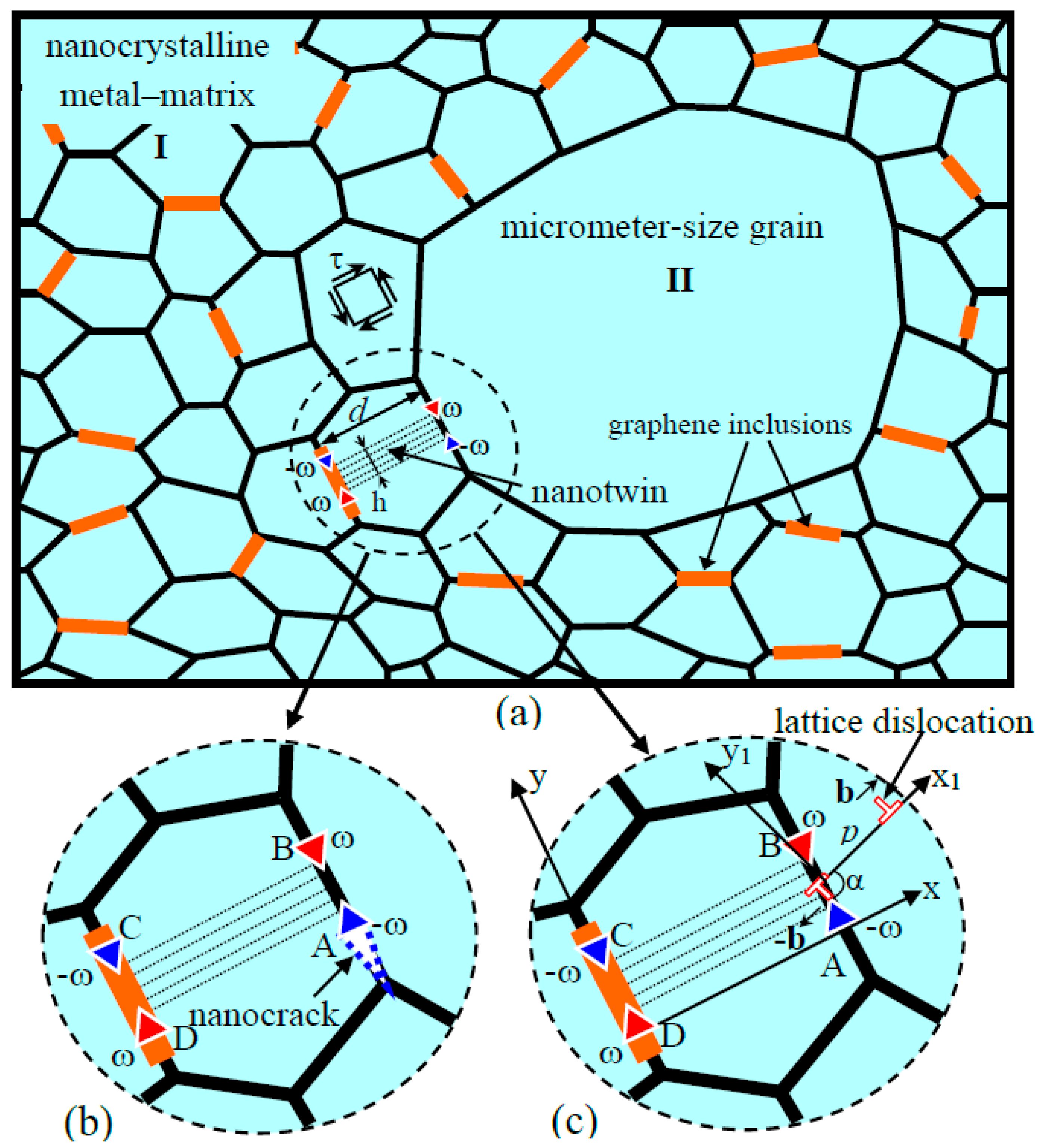
Consider a two-dimensional model of bimodal metal–graphene nanocomposite with an average grain size of metal–matrix
under mechanical load (
Figure 1). In the framework of the model, the bimodal metal–graphene nanocomposite consists of nanometer-size metal–matrix I reinforced by homogeneously dispersed graphene inclusions and micrometer-size grains II embedded into a nanocrystalline metal–matrix (
Figure 1). The chemical compositions of large grains II and the nanocrystalline metal–matrix I are identical.
It is well known that specific plastic deformation mechanisms such as deformation twinning, grain boundary migration and grain boundary sliding effectively operate in materials with nanocrystalline structure. It is suggested that the external stress
initiates deformation twinning in the nanocrystalline metal–matrix. In this situation, the graphene inclusions act as effective obstacles for the deformation twinning enhancement. Thus, the suppression of specific deformation modes (deformation twinning, etc.) and the absence of both lattice dislocation accumulation and associated strain hardening during plastic deformation often lead to plastic strain instability. Besides, the deformation twinning leads to formation of dipoles AB and CD of disclinations having strengths
(hereinafter called
-disclination dipole;
Figure 1a). The disclination dipoles AB and CD compose a
-disclination quadrupole configuration with sizes
and
(
Figure 1a). The disclination dipoles and quadrupoles serve a powerful stress sources. Its local can be relieved through either crack formation (
Figure 1b) or local plastic deformation occurring through a new mode of the lattice dislocation emission into large grains II from grain boundaries (
Figure 1c). In the former case, the metal–graphene nanocomposite deformed by the deformation twinning tends to show brittle behavior. If plastic relaxation of the stresses created by dipoles of disclinations due to the lattice dislocation emission dominates, the twinning deformation does not initiate cracking. In this situation, the metal–graphene nanocomposite with bimodal structure tends to exhibit a good ductility.
Within the model, a lattice dislocation with the Burgers vector
(hereinafter called
-dislocation) is emitted from the grain boundary AB into the adjacent large grain II under the combined action of the external shear stress
and the shear stress field created by the disclination quadrupole (
Figure 1c). The lattice edge dislocation slips along a crystallographic plane that makes the angle
with the grain boundary AB plane (
Figure 1c). In terms of the continuum approach, the emission of the lattice
-dislocation can be represented as formation of a dipole AB of lattice dislocations with Burgers vectors
(
Figure 1c).
Further, consider the energy characteristics of the dislocation emission. To analyze the energy characteristics, a semi-analytical energetic approach, which is based on the calculation of the total energy of the defect structure under consideration was used. In the framework of this approach, the difference between the total energies characterizing the structure after and before the transformation event is calculated. It is considered that a transformation of the defect system energetically favorable if the total energy of the defect system decreases and energetically unfavorable if this transformation leads to an increase in the total energy of the defect system.
The dislocation emission process (
Figure 1) is specified by the energy difference
, where
is the energy of the initial state of the system containing the disclination quadrupole ABCD (
Figure 1a), and
is the energy of the system after the dislocation emission (
Figure 1c). Such a transformation of the defect system is energetically favorable if
.
The energy difference
is determined by the expression:
Here denotes the proper energy of the dislocation dipole of the -dislocations; is the energy that characterizes the interaction between the -disclination quadrupole and the -dislocations dipole and is the interaction energy of the applied shear stress with mobile lattice -dislocation.
The self energies
of dipole of
-dislocations are given by standard formula [
17]:
where
,
is the shear modulus,
is the Poisson ratio,
is the path moved by the mobile
-dislocation and
is the cut-off radius of the stress fields of
-dislocations.
To calculate the interaction energy
between deferent defects, we used the standard procedure of calculating the work spent to nucleate a defect (or a group of defects) in the stress field of another defect (see, for example, [
17] for details). In doing so, according to Mura’s method [
18], the energy
can be found as a work for the generation of the
-dislocations dipole in the stress field of the
-disclination quadrupole ABCD using the following formula:
where
is the shear stress of
-disclination quadrupole ABCD acting in the slip plane of the
-dislocations dipole (
Figure 1c). The non-vanishing components of the stress tensor
of the disclination quadrupole ABCD in the coordinate system
(with the
-axis being parallel with the disclination lines,
Figure 1c) are determined by the standard formulas [
19]
These components cause the shear stress
acting along the
-axis of the
coordinate system (
Figure 1c). From the geometry of the
and
coordinate systems (
Figure 1c) follows:
where
,
,
and
.
Since the integration in Formula (8) is made along the
-axis of the
coordinate system at
(
Figure 1c), the coordinate transformation is as follows:
With substitution of the expressions (4)–(6) into Formula (3) and integration, we found the final expression for the interaction energy
where
is the distance between the point A and the immobile
-dislocation.
The energy that specifies the interaction of the external shear stress
with dislocation dipole is given as:
3. Results and Discussions
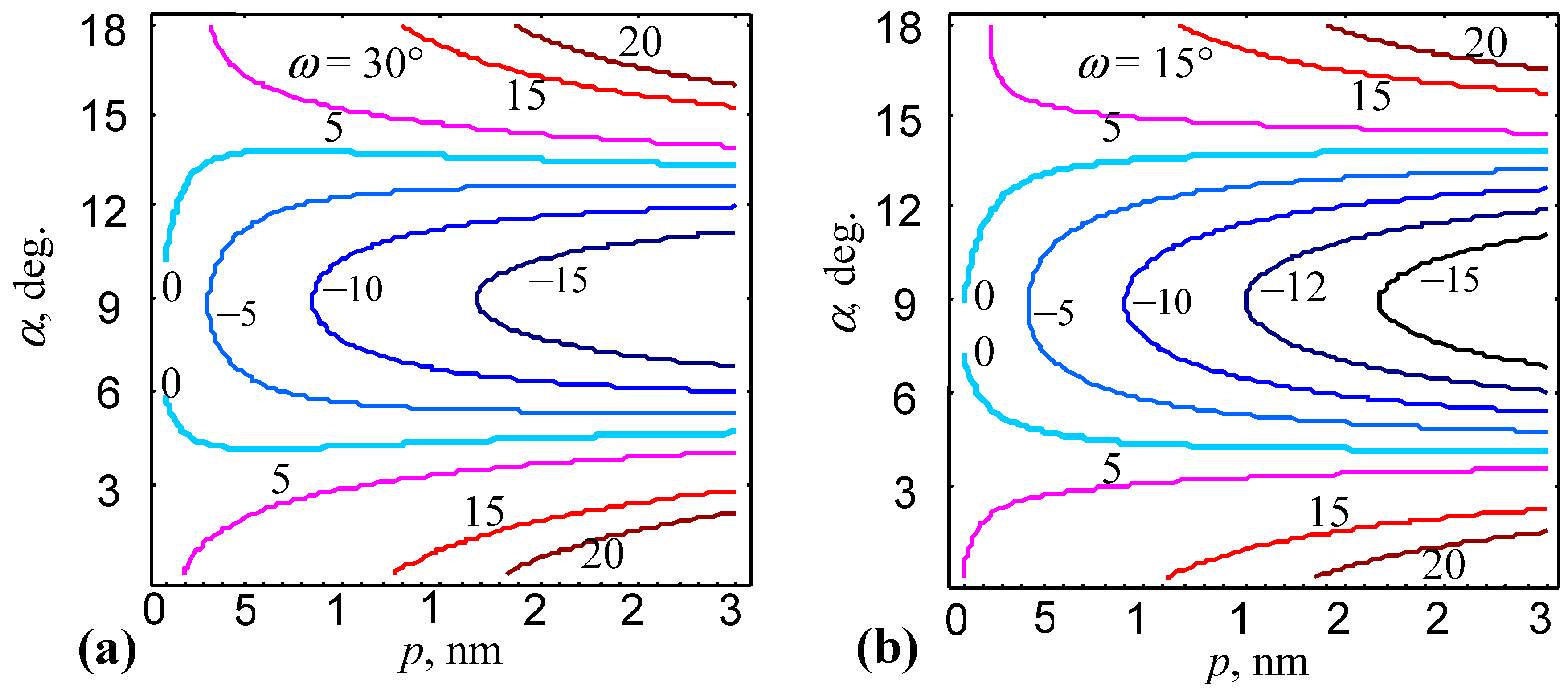
Let us analyze the dependences of the energy change
on characteristics of the system under consideration in the exemplary cases of bimodal Cu-graphene composite. First, with Formulas (1), (2), (7) and (8), we calculated the dependences of
on the distance
moved by the
-dislocation in the grain interior and angel
. In our calculations, we used the following typical values of material parameters [
20,
21]:
G = 48 GPa,
,
nm and
. Other parameters of the defect system were taken as
nm,
nm and
. Value of the external shear stress
was taken as 500 MPa (this value is typical for Cu-graphene composites).
The maps of the energy difference
(in units of eV/nm) on the angle
and the distance
are presented in
Figure 2. As it follows from
Figure 2, the emission of the lattice dislocations was energetically favorable in a certain range of the angle
:
, in the case of
(
Figure 2a), and
, in the case of
(
Figure 2b). As it is seen in
Figure 2, the range of the energetically favorable angles
expanded with rising of the strength
of the disclination quadrupole. This tendency illustrates the significant effect of disclination quadrupole produced by deformation twinning on the lattice dislocation emission.
Now let us consider the generation of a nanocrack in the stress field of a dipole AB of
-disclinations formed due to deformation twinning (
Figure 1b). Following the approach [
22], the nanocrack of length
can be generated at the grain boundary fragment adjacent to the disclination with the strength
of the dipole configuration (
Figure 1b). The condition for the nanocrack generation is given as [
22]:
, where
,
with
being the specific (per unit area) free surface energy, and
being the specific (per unit area) grain boundary energy.
The condition
allowed one to calculate the critical lengths
and
of the nanocrack. The generation and growth of the nanocrack in the length interval
occurred with the aid of thermal fluctuations. The nanocrack growth in the length interval
was energetically favorable and occurred in the athermal way. Further nanocrack growth (at which the nanocrack length exceeds the second critical length:
) was energetically unfavorable. Following [
22], we took
, where
is the lattice parameter. Then, with both Formula (9) and the condition
, we found values of the disclination dipole size
and the angel
corresponding to
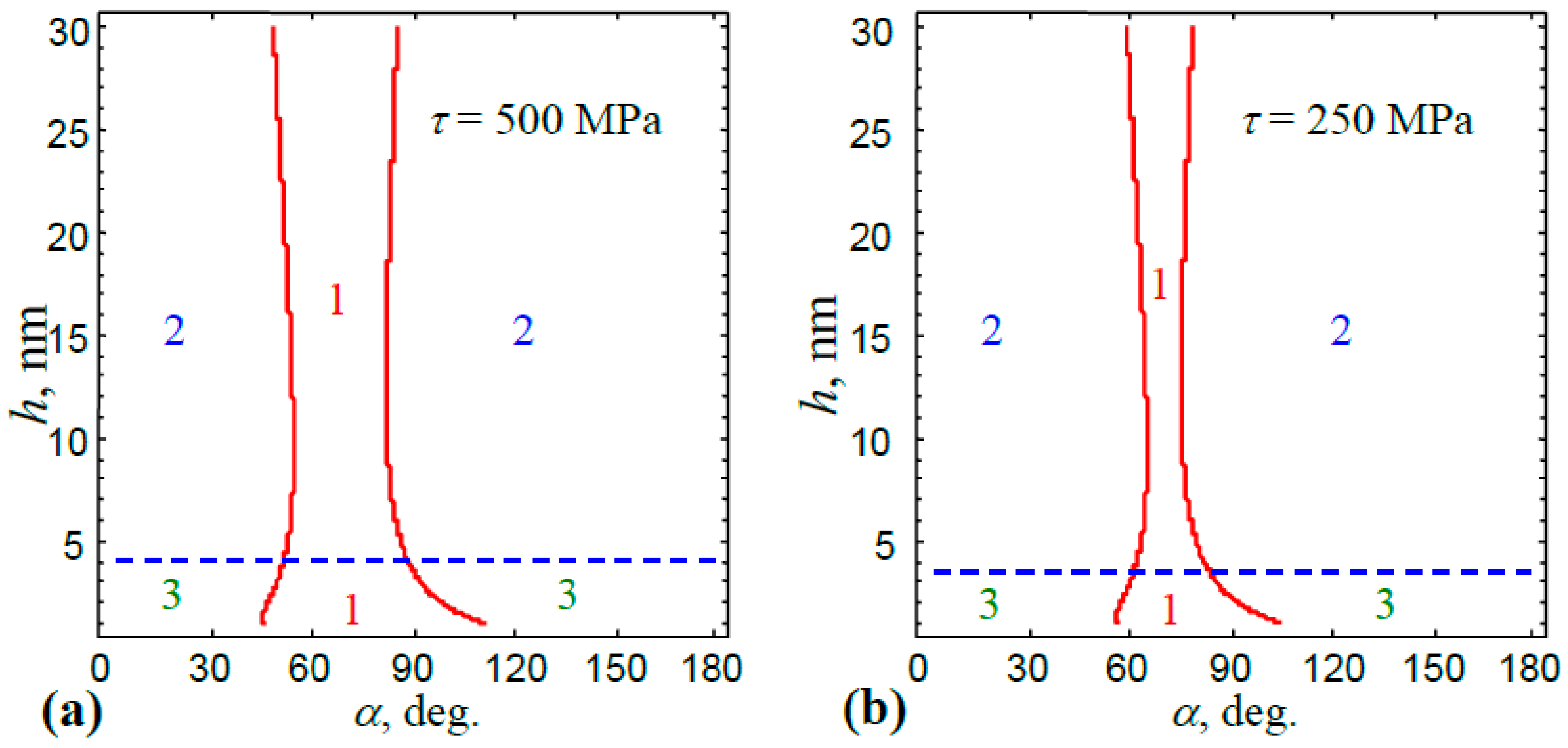
. Let us make these calculations in the exemplary cases of bimodal Cu-graphene nanocomposites with
J/m
2 and
J/m
2 [
23].
Figure 3 shows the map of parameters
, which was divided into regions where the formation of a nanocrack and/or the emission of lattice dislocations was energetically favorable or unfavorable. The formation of a nanocrack was favorable in the region above and unfavorable in the region below the horizontal dashed line (
Figure 3). In region 1, the emission of lattice dislocations was more energetically favorable than the nucleation of nanocracks. At the same time, in the region 2, the generation of nanocracks was energetically favorable only (
Figure 3). Finally, in region 3, both the formation of nanocracks and the emission of lattice dislocations were energetically unfavorable (
Figure 3). As it follows from
Figure 3, the region of energetically favorable the lattice dislocation emission reduced significantly when the value of the external shear stress decreased.


