Article

Study on a Large-Scale Three-Dimensional Ultrasonic Plastic Welding Vibration System Based on a Quasi-Periodic Phononic Crystal Structure

1
Shaanxi Key Laboratory of Ultrasonics, Shaanxi Normal University, Xi’an 710119, Shaanxi, China
2
School of Information Engineering, Yulin University, Yulin 719000, China
*
Author to whom correspondence should be addressed.
Crystals 2020, 10(1), 21; https://doi.org/10.3390/cryst10010021
Submission received: 24 December 2019 / Revised: 27 December 2019 / Accepted: 31 December 2019 / Published: 3 January 2020

Abstract

:
The uniformity of amplitude distribution and amplitude gain are two main factors affecting the performance of ultrasonic welding vibration system. In order to improve the uniformity of amplitude distribution and amplitude gain of welding surface to enhance the performance of the vibration system, a new design method of a large-scale three-dimensional ultrasonic plastic welding vibration system based on a quasi-periodic phononic crystal structure is proposed. In this method, the composite horn combined with a conical section and a cylindrical section can effectively improve the output amplitude gain of the welding surface. In addition, the method forms a quasi-periodic phononic crystal structure by slotting in a large-scale three-dimensional tool head, and utilizes the band gap property of the structure to effectively suppress lateral vibration of the tool head and improve the amplitude distribution uniformity of the tool head’s welding surface. However, when the size of the tool head is relatively large, the quasi-periodic phononic crystal structure cannot suppress the lateral vibration very well. Therefore, the paper processes fan-shaped slopes on the output surface of the tool head which can further improve the uniformity of the amplitude distribution and amplitude gain. Finally, the simulation analysis and experiments show that the design method can optimize the large-scale three-dimensional ultrasonic plastic welding system, improve the uniformity of the vibration distribution and increase the output amplitude gain of the welding surface.

1. Introduction

Ultrasonic plastic welding technology has been widely used because of its advantages of fastness, flexibility, stable welding process, low cost, and environmental protection [1]. The ultrasonic plastic welding system is mainly composed of a transmission system, a control system, an ultrasonic generator, an ultrasonic vibration system, and a mechanical device. Among them, the ultrasonic vibration system is a core component of the ultrasonic plastic welding equipment, mainly including the transducer, the horn, and the tool head [2]. The tool head needs to be specially designed according to the welding object. The common ones are rectangular, square, cylindrical, etc. The rectangular tool head is usually used to weld large-scale flat-shaped weldments, but the large-scale rectangular tool head is susceptible to lateral vibration. Especially for tool heads with a lateral dimension greater than a quarter wavelength, the lateral vibration and longitudinal vibration are prone to coupling, resulting in uneven distribution of the amplitude of the welding surface of the tool head, which can affect the welding quality [3]. Secondly, due to the coupled vibration, the output amplitude of the large-scale tool head on the welding surface is generally small [4]. In response to the above problems, scholars at home and abroad have carried out relevant research.
Japanese scholar Mori proposed the theory of apparent elasticity from the perspective of an engineering application [5]. Lin et al. applied the apparent elasticity to the rectangular tool head and studied the generation and suppression of coupled vibration [2]. According to the actual use needs of the welding mold, Zhou et al. used the theory of apparent elasticity to study the tool head [6,7]. Liang et al. applied the structural optimization function of the finite element analysis software to optimize the structure of the rectangular tool head, but there was no specific theoretical support [8,9,10]. Lin et al. applied phononic crystal theory to the study of circular and rectangular tool heads. For example, Wang applied phononic crystal theory to cylindrical tool heads and Zhao applied phononic crystal theory to rectangular tool heads [11,12,13]. Up to now, there have been few studies on the three-dimensional large-scaled tool heads whose two lateral dimensions are comparable to their longitudinal dimensions. Based on this, the paper proposes a large-scale three-dimensional ultrasonic plastic welding vibration system based on a quasi-periodic phononic crystal structure. The research uses the band gap theory of quasi-periodic phononic crystal, combined with the fan-shaped slopes structure, composite horn, and COMSOL simulation to realize the optimal design of an ultrasonic welding vibration system, which can achieve the goal of improving the uniformity of displacement distribution of welding surface, shortening welding time, improving welding production efficiency, and increasing the system’s stability. At the same time, based on numerical simulation analysis, some large-scale three-dimensional ultrasonic welding vibration systems were designed and processed, and their input impedance and vibration displacement distribution were tested and verified experimentally.

2. Theoretical Analysis of a Large-Scale Three-Dimensional Ultrasonic Plastic Welding Vibration System

2.1. Coupled Vibration Theory of a Large-Scale Three-Dimensional Vibrating Body

When the lateral and longitudinal dimensions of the tool head can be compared, it can be called a large-scale ultrasonic vibrating body. Due to the Poisson effect, the vibrating body will generate severe lateral vibration. Moreover, the lateral vibration and the longitudinal vibration are coupled with each other. At this time, the three-dimensional coupled vibration theory should be used to analyze the vibrating body [5].
Japanese scholar Mori proposed the theory of apparent elastic method when studying the multi-dimensional coupled vibration of ultrasonic vibrating body. According to the theory, under the premise of considering only the expansion deformation and neglecting the shear deformation, the vibration of the material with uniform material can be regarded as the coupling of vertical vibrations that are perpendicular to each other. The vibration in different directions has different apparent elastic constants [14,15]. For large-scale tool heads with free surfaces, the length, width and height are l, b, and h. The resonance frequency equation of a large-scale three-dimensional vibrating body is given in the literature [1] based on the basic principles of elastic mechanics and apparent elasticity:
i 2 j 2 m 2 l 2 b 2 h 2 A 3 ( i 2 j 2 l 2 b 2 + j 2 m 2 b 2 h 2 + i 2 m 2 l 2 h 2 ) A 2 + ( 1 v 2 ) ( i 2 l 2 + j 2 b 2 m 2 h 2 ) A + 2 v 3 + 3 v 2 1 = 0
In the formula, A = c 2 π 2 ω 2 , c 2 = E ρ . Among them, c is the sound velocity of one-dimensional longitudinal vibration in a slender rod, ω is the circular frequency of three-dimensional vibration; i, j, and m respectively corresponds to different vibration modes of the vibrating body; ν is Poisson’s coefficient, and E is Young’s modulus. It can be known from formula (1) that the resonant frequency of a large-scale three-dimensional vibrating body is determined by the material and size of a given vibrating body. After the geometric size and material of the large-scale three-dimensional vibration body are given, the resonance frequency can be obtained by formula (1). When the lateral dimension of the vibrating body is large, the lateral vibration has a great influence on the longitudinal vibration, which makes the output amplitude of the welding surface very uneven. Therefore, in order to ensure the welding surface’s displacement uniformity of the large-scale three-dimensional vibrating body, the lateral vibration in two directions (X and Y) must be effectively suppressed [2].
It is very convenient to study the coupled vibration of large-scale vibration system with a regular shape by the theory of an apparent elasticity method. It can easily get the resonance frequency of the coupled vibration system. However, this method cannot give a more accurate design guidance for the vibration displacement distribution and lateral vibration suppression of the system. In order to deeply understand the vibration distribution and vibration suppression of the coupled vibration of large-scale three-dimensional ultrasonic vibration system, and also to optimize the three-dimensional ultrasonic welding and processing systems, we use the band gap theory of quasi-periodic phononic crystals to study the coupling vibration system and its suppression.

2.2. Band Gap Characteristics of a Quasi-Periodic Phononic Crystal Structure

Phononic crystal is a kind of artificial periodic structure with periodic distribution of elastic constant and density. The propagation characteristics of its mechanical wave can be affected by changing its periodic structure or geometric properties [16]. Phononic crystals can isolate vibrations in a specific frequency range, also known as band gap [17]. The vibration in the band gap is attenuated by the waves’ interference in the periodic structure, therefore it has a broad application prospect in the fields of vibration reduction and noise reduction, such as precision mechanical platform vibration reduction, automobile brake noise reduction, new acoustic devices, and so on. However, in practical engineering applications, due to the limitations of the material’s own processing technology and performance, there may not be a perfect periodic structure. Sometimes, in order to meet some specific needs, periodic structures with small imperfections may be manufactured, such as quasi-periodic structures. Quasi-periodic structure is a structure between disordered structure and periodic structure. It has the characteristics of short-range disordered and long-range ordered structure. Quasi-periodic structures also have band gaps, and the elastic wave can also be regulated by using the band gap characteristics of the quasi periodic phononic crystal structure [18].
According to Section 2.1, the lateral vibration of the large-scale three-dimensional vibrating body is obvious, which will result in uneven displacement of the welding surface of the vibrating body, affecting the welding quality. In order to improve the welding effect, the vibration tool head with periodic slots structure can be designed based on the band gap theory of the quasi-periodic phononic crystal, and the working frequency of the ultrasonic plastic welding vibration system can be designed in the lateral vibration band gap of the large-scale three-dimensional tool head. In this way, the lateral coupling vibration of the tool head can be suppressed.

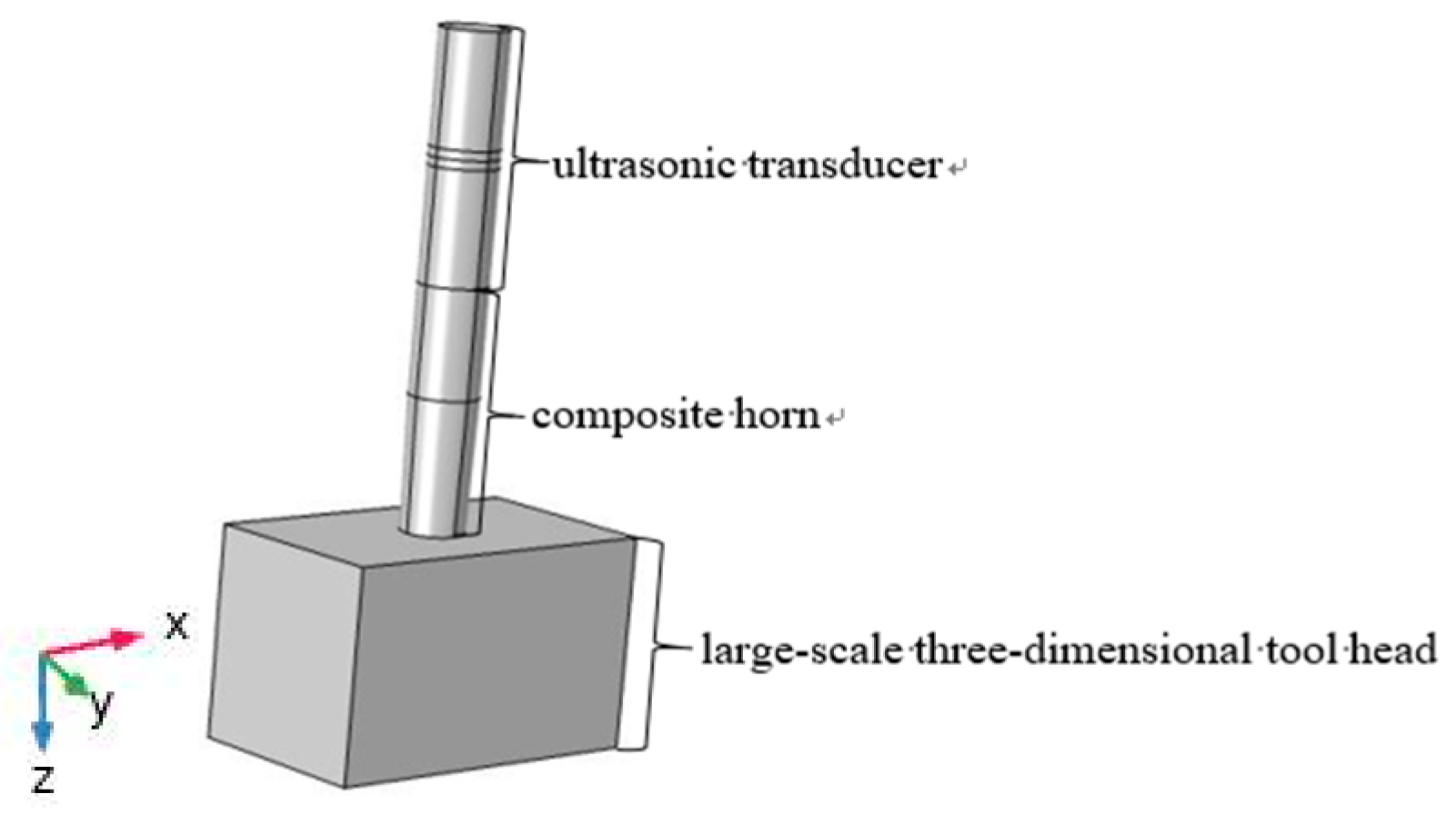
3. Analysis of a Large-Scale Three-Dimensional Ultrasonic Plastic Welding Vibration System Based on a Quasi-Periodic Phononic Crystal Structure

An ultrasonic plastic welding vibration system mainly includes three parts: an ultrasonic transducer, a composite horn, and a large-scale three-dimensional tool head. The structure of the system is shown in Figure 1.
The working frequency of the high-power ultrasonic welding vibration system is generally between 15 and 20 kHz. The working frequency of the designed system in this paper is set at around 20 kHz. In order to achieve resonance, the transducer, horn, and tool head are generally designed as a half-wavelength structure. Thus, the height of the sandwich transducer is set to 124 mm, the height of the horn is 122 mm, the height of the three-dimensional tool head is 115 mm, the length is 180 mm, and the width is 106 mm. In addition to a piezoelectric ceramic crystal stack, all other materials are made of hard aluminum, and the transducer is excited along the Z-axis direction. Firstly, the three-dimensional geometric model of the vibration system is established by using Comsol Multiphysics. After creating the definitions, adding materials, defining the physics fields, and setting the Mesh, “Study” is added to calculate the “Eigenfrequency”. Finally, we can obtain the characteristic modality of the system, and using the “Results” to calculate and draw the longitudinal displacement distribution line diagram of the welding surface along the X (length) and Y (width) directions. Figure 2 shows the vibration pattern of the system. Figure 3 and Figure 4 respectively show the longitudinal relative displacement distribution of the tool head’s welding surface in the X and Y directions. It can be seen from the figures that, due to the Poisson effect, the tool head whose length and width are not greatly different from the height dimension produces severe lateral vibration in the X and Y directions.
It can be seen from Figure 3 and Figure 4 that the longitudinal relative displacement of the welding surface changes from 0.0032 to 0.0044 in the X direction, and from 0.0004 to 0.0035 in the Y direction. The variation range is large, indicating that the amplitude distribution is very uneven, and the amplitude of the output is very small. In order to control the lateral vibration of the system, improve the uniformity of the displacement distribution, and increase the output amplitude, the paper optimizes the design of the large-scale three-dimensional ultrasonic plastic welding vibration system, and takes COMSOL as the tool to realize the control to the amplitude uniformity and the amplitude gain by using the periodic slots of quasi-periodic phononic crystal structure and the composite horn.

3.1. Design of Transducer
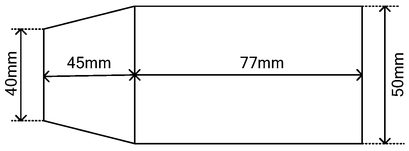
The ultrasonic plastic welding machine needs high frequency longitudinal vibration, so the longitudinal sandwich piezoelectric ceramic composite transducer is selected, which is composed of a metal front cover plate, piezoelectric ceramic crystal stack, and metal back cover plate. A piezoelectric ceramic crystal stack selected PZT-4, density ρ = 7500 kg/m3, elastic modulus E = 64.5 GPa, Poisson’s ratio σ = 0.32, radius set to 25 mm, thickness 6 mm, 2 pieces. The front and rear covers are made of hard aluminum, equal-section cylinder, and the same cross-sectional area as the piezoelectric ceramic crystal stack, c = 5100 m/s, density ρ = 2790 kg/m3, elastic modulus E = 7.15 × 10¹⁰ N/m2, Poisson’s ratio σ = 0.34, and the vibration displacement wave nodal surface is located in the middle of the piezoelectric ceramic crystal stack. Using the solution of the vibration equation, the frequency equation is obtained [19]:
tan ( k 1 l 1 ) = ρ c 1 ρ 2 c 2 cot ( k 2 l 2 )
Adjust the length of front and rear cover plates according to formula 2 and simulation results. Finally, set the length of front and rear cover plates as 56 mm, and the transducer’s dimension diagram is shown in Figure 5.

3.2. Design of Horn

In high-power ultrasonic welding vibration systems, increasing the amplitude within a suitable range can shorten the welding time. The single horn usually has a small amplitude. In order to get a larger amplitude, the composite horn is used in this design. A common single type of horn is conical, exponential, and stepped. The conical type horn is easy to make, and the maximum stress at the section mutation is also the smallest, but the amplitude amplification coefficient is also relatively small [20]. The exponential type horn has stable performance, large amplitude, medium amplification coefficient, but the production is more complicated. The stepped type horn has large amplitude amplification coefficient, and the manufacture is relatively simple, but, in the step transition place, it is easy to cause great stress concentration, which leads to fatigue fracture of the horn [21]. Therefore, this paper makes use of the advantages of stepped and conical horn to produce a conical and cylindrical composite ultrasonic horn, which not only has a large amplitude amplification coefficient, but also can reduce stress concentration through a conical transition section [22]. The dimension diagram of the composite horn is shown in Figure 6.
As shown in the figure above, the bottom diameter length of the cone section is set to D, the top diameter length of the cone section is set to d, and the length is set to l 8 . The diameter of the cylinder section is also set to D, and the length is l 9 . The taper coefficient is set to φ, φ = ( D d ) / D * l 8 . According to the one-dimensional wave theory of longitudinal vibration [23]:
2 ε x 2 + 1 S + S x ε x + k L 2 ε = 0
In the above formula:
ε is the particle displacement function;
S is the cross-sectional area of the horn;
k L is the number of circular waves. ( k L = circular frequency/longitudinal wave propagation speed in the horn).
The frequency equation of the longitudinal vibration of the composite horn can be recorded as follows:
tan ( k L l 8 ) = D d * φ k L tan [ k L l 9 + arctan ( φ k L ) ]
It can be seen from the above formula that the longitudinal vibration frequency of the composite horn is related to the length of the cone section and the cylinder section. The system working frequency is set near 20 kHz, the bottom radius of the cone section is set to 25 mm, and the top radius is set to 20 mm. Adjust the length according to the formula and simulation results. Finally, set the cone section length of composite horn to 45 mm, and set the cylinder section length to 77 mm.

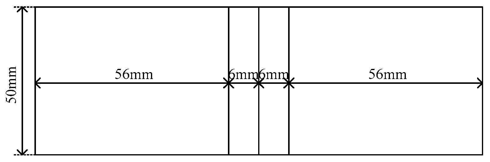
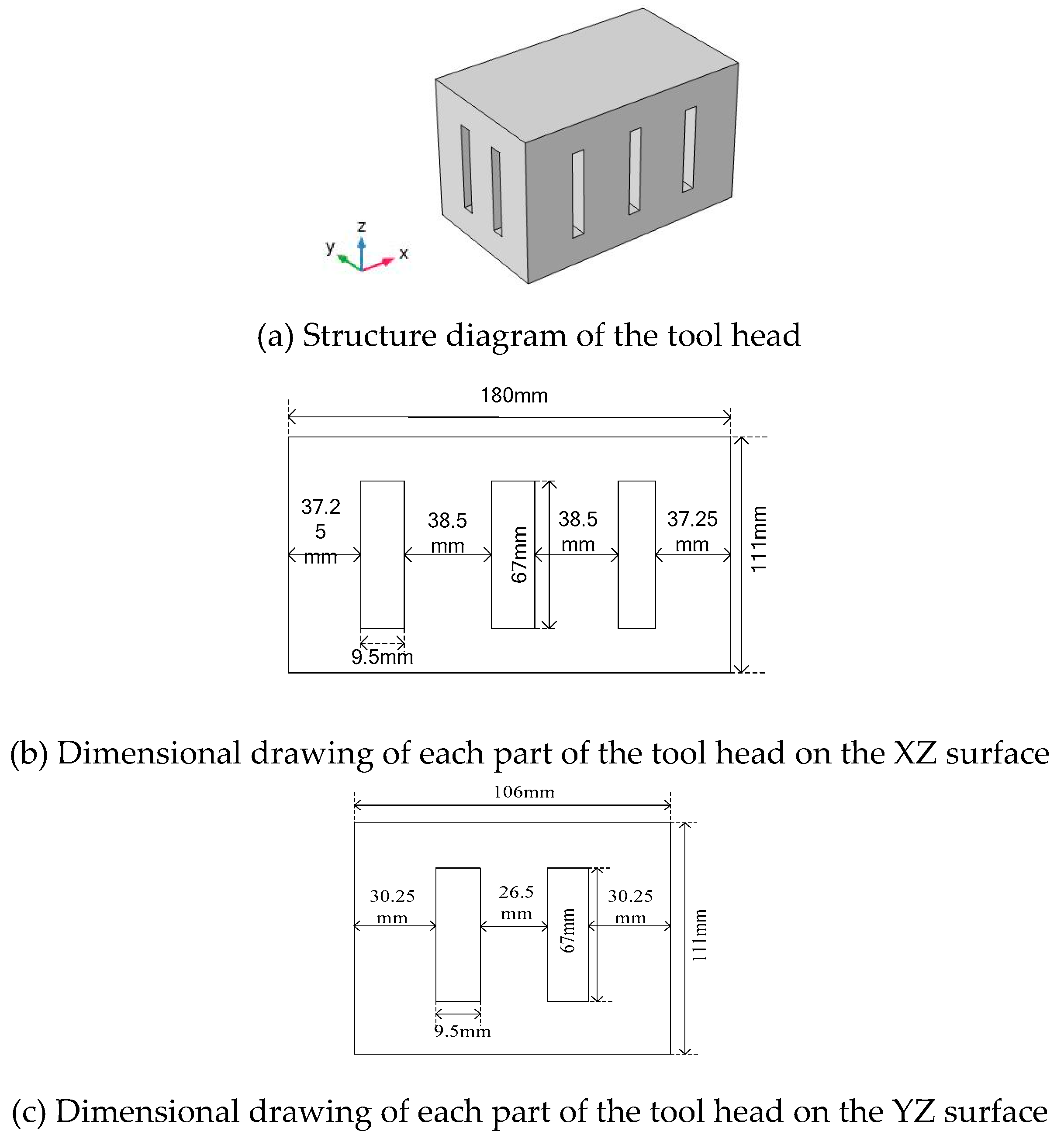
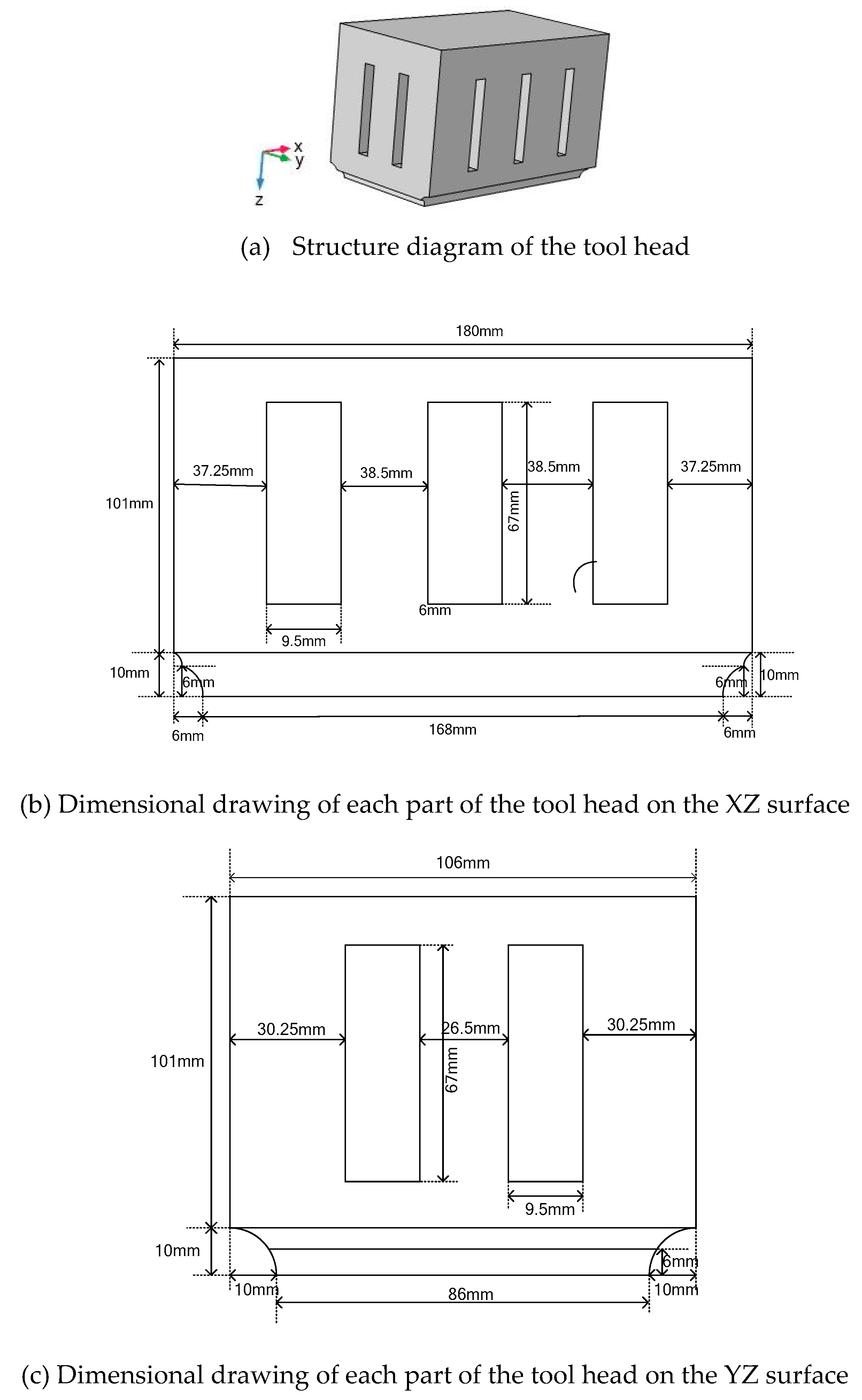
3.3. Design of Large-Scale Three-Dimensional Tool Head Based on Quasi-Periodic Phononic Crystal Structure

A large-scale three-dimensional tool head with a length of 180 mm, a width of 106 mm, and a height of 111 mm is designed. For the tool head, its height and its two lateral dimensions (length and width) are numerically comparable. Under the influence of Poisson effect, the tool head will produce serious lateral vibration along the X and Y directions, resulting in uneven longitudinal vibration displacement of the welding surface. In order to ensure the working efficiency of the welding system and reduce the influence of the coupling vibration, the paper optimizes the tool head by the way of processing three periodic slots along the X directions and processing two periodic slots along the Y directions of the tool head to form a large-scale three-dimensional tool head based on the quasi-periodic phononic crystal structure. The optimized tool head structure diagram is shown in Figure 7a, the dimension diagram of the XZ plane is shown in Figure 7b, and the dimension diagram of the YZ plane is shown in Figure 7c.

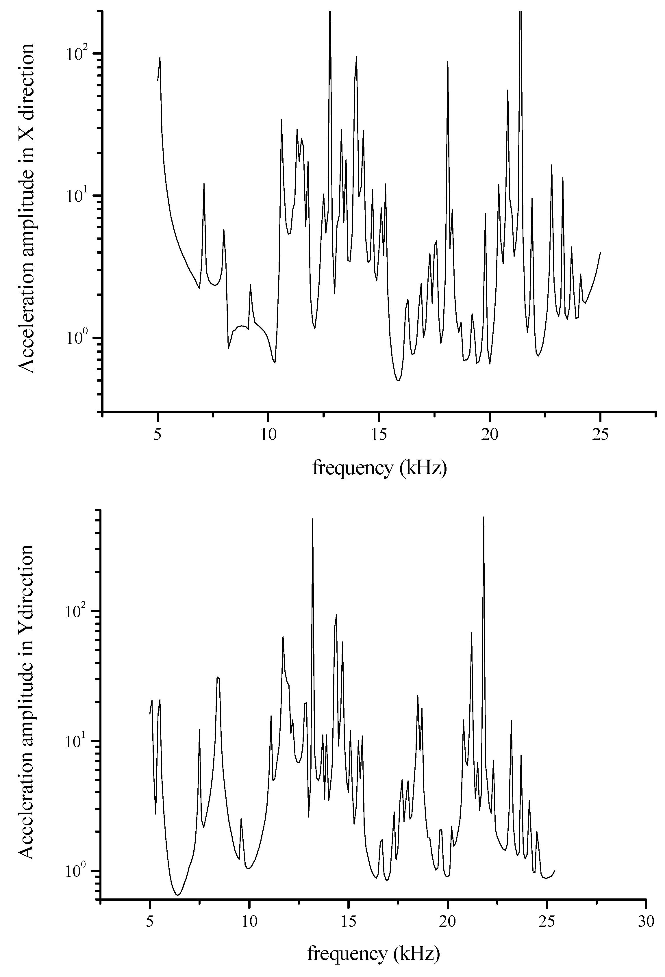
3.4. Band Gap Analysis of a Three-Dimensional Tool Head Based on a Quasi-Periodic Phononic Crystal Structure

Using COMSOL Multiphysics to apply an acceleration of 1 m/s2 to the X-axis and Y-axis ends of the slotted large-scale three-dimensional tool head, apply the probe at the opposite end. Then, the acceleration response curves in the X and Y directions of the optimized tool head are obtained by frequency domain calculation. The result is shown in Figure 8. The figure shows the relationship between acceleration amplitude and the frequency. The frequency range with amplitude less than 1 can be approximated as band gap. It can be seen from the figure that there are band gaps in X and Y directions near 20 kHz. Therefore, setting the longitudinal resonance frequency of the ultrasonic plastic welding vibration system to around 20 kHz, which can allow it to locate in the lateral band gap of the tool head to realize the suppression of vibrations in the X and Y directions, make the vibration mode more single, and improve the uniformity of the longitudinal displacement distribution.

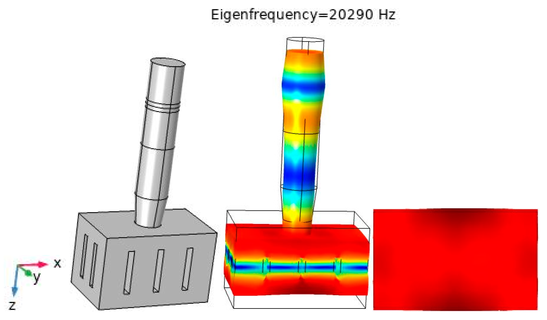
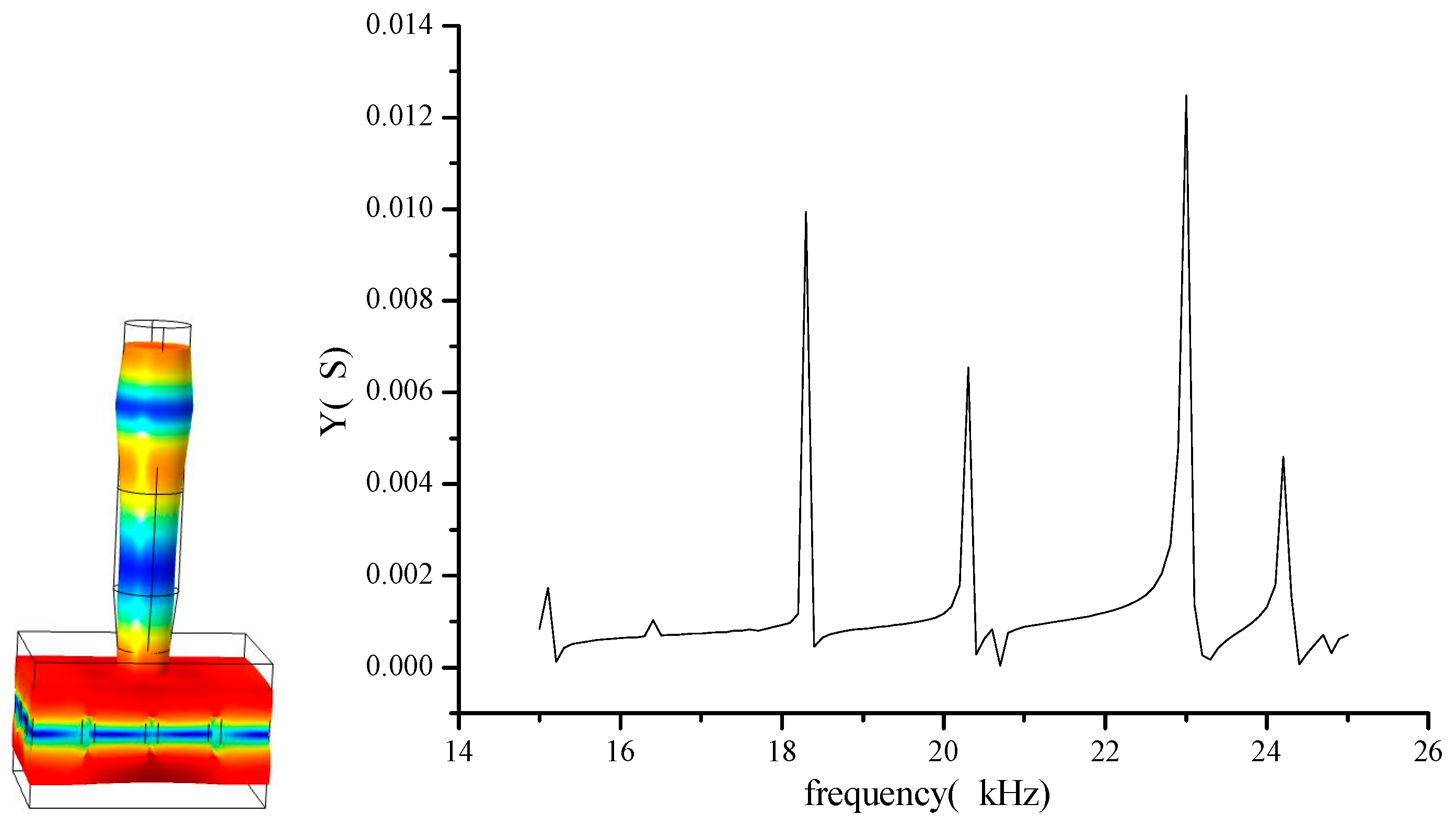
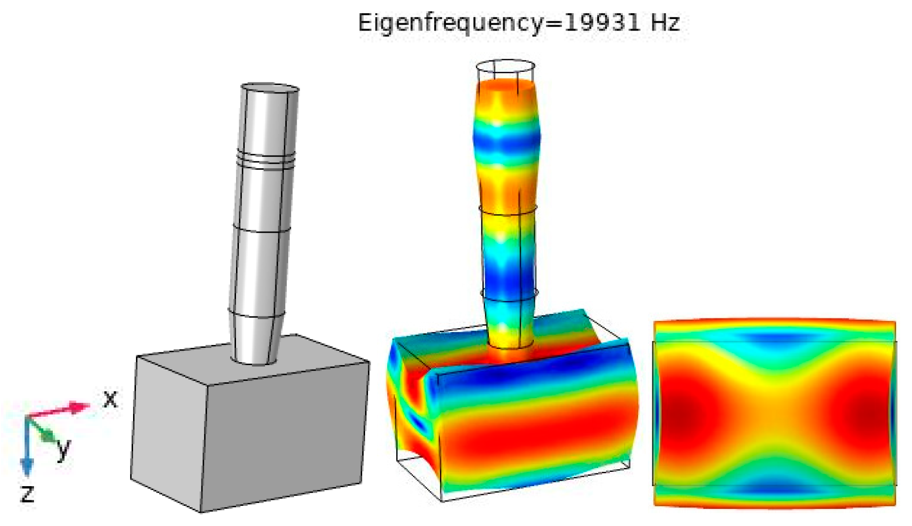
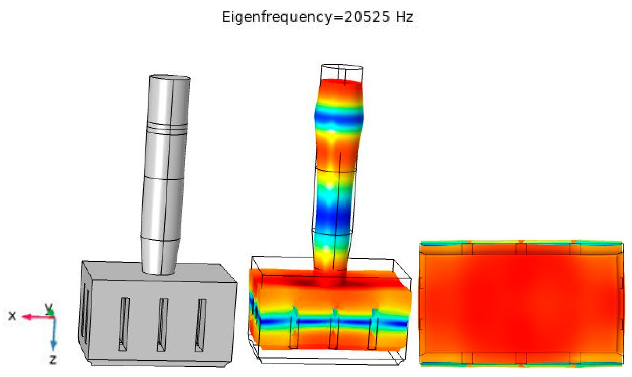
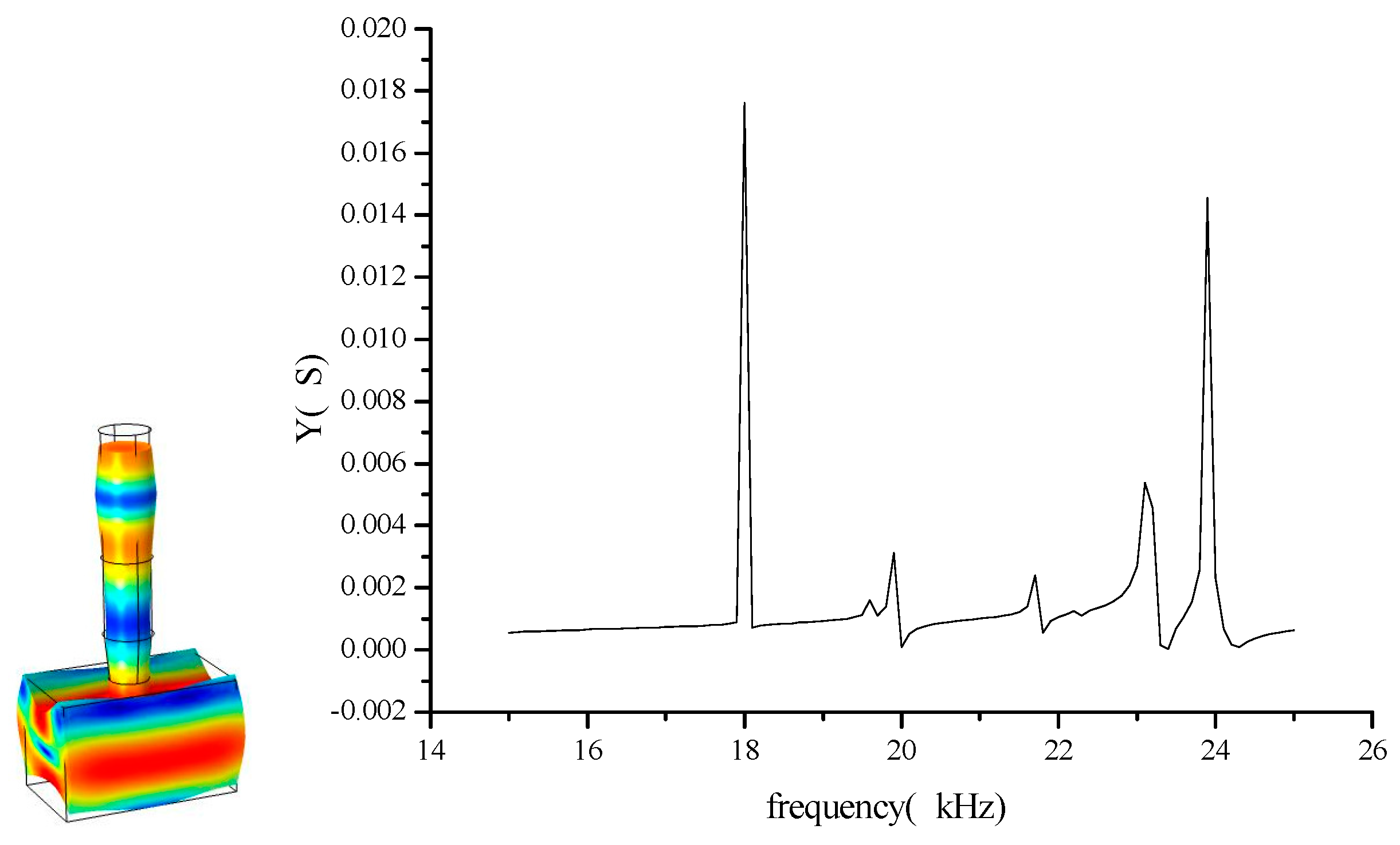
3.5. Finite Element Simulation of a Large-Scale Three-Dimensional Ultrasonic Plastic Welding Vibration System Based on a Quasi-Periodic Phononic Crystal Structure

The optimized system is simulated using COMSOL. In order to simplify the model, the influence of prestressed bolts is not considered here. Add “Research” to Comsol Multiphysics, calculate the “Eigenfrequency”, and use the calculation results to plot the longitudinal displacement distribution line diagram of the weld surface along the X (length) and Y (width) directions. The structure and vibration mode diagram of the optimized large-scale three-dimensional ultrasonic plastic welding vibration system is shown in Figure 9. The relative displacement distribution diagram of the welding surface along the X and Y directions is shown in Figure 10. The comparison of the longitudinal relative displacement distribution between the optimized system and the unoptimized system is shown in Figure 11.
The working frequency of the ultrasonic plastic welding vibration system based on the quasi-periodic phononic crystal structure is 20,290 Hz, which is just located within the band gap of the lateral vibration of the tool head. From the comparison of the longitudinal relative displacement distribution of the welding surface in Figure 11, it can be seen that the longitudinal output displacement of the system based on the quasi-periodic phononic crystal structure is more uniform than that of the system without the quasi-periodic phononic crystal structure, which shows that the lateral vibration in X and Y directions is effectively controlled because of the influence of the quasi-periodic phononic crystal structure, which makes the longitudinal displacement of the tool head more uniform. In addition, it can also be seen from Figure 11 that the existence of the composite horn and the periodic slots structure of quasi-periodic phononic crystal can significantly increase the longitudinal amplitude gain of the welding surface, which can effectively shorten the welding time and improve the working efficiency of the system.

4. Optimal Design pf Large-Scale Three-Dimensional Ultrasonic Plastic Welding Vibration System Based on a Quasi-Periodic Phononic Crystal Structure

It can be seen from Figure 10 that, although the periodic slots structure of the quasi-periodic phononic crystal can suppress the lateral vibration in the X and Y directions which makes the longitudinal relative displacement more uniform. However, the longitudinal relative displacement in the length Y direction ranges from 0.0043 to 0.00475, which is still not uniform enough. That is to say, when the size of the three-dimensional vibrating body is too large, the lateral vibration cannot be better suppressed by the periodic structure alone. Therefore, the three-dimensional tool head needs to be further optimized.
In order to further optimize the uniformity of the longitudinal displacement of the welding surface, four fan-shaped slopes are processed along the four sides of the tool head welding surface, forming a large-scale three-dimensional tool head with fan-shaped slopes (the dimensions of the transducer and the horn remain unchanged). The optimized tool head structure diagram is shown in Figure 12a, the dimension diagram of the XZ plane is shown in Figure 12b, and the dimension diagram of the YZ plane is shown in Figure 12c.
In order to observe the change of amplitude uniformity and amplitude gain more clearly, the paper simulates and analyzes the system with fan-shaped slopes structure and the system without fan-shaped slopes structure. The optimized structure diagram and modal diagram of the system are shown in Figure 13. The comparison results of the longitudinal relative displacement distribution of the optimized system with fan-shaped slopes and system without fan-shaped slopes are shown in Figure 14.
It can be seen from Figure 14 that the system with quasi-periodic phononic crystal periodic slots structure and fan-shaped slopes has a more uniform longitudinal displacement distribution than the system based on a quasi-periodic phononic crystal periodic groove structure, and the longitudinal vibration relative displacement is further improved, that is to say, the vibration system processed fan-shaped slopes and the periodic slots not only increases the uniformity of the longitudinal relative displacement distribution of the welding surface, but also increases the longitudinal amplitude gain which can reduce welding time.

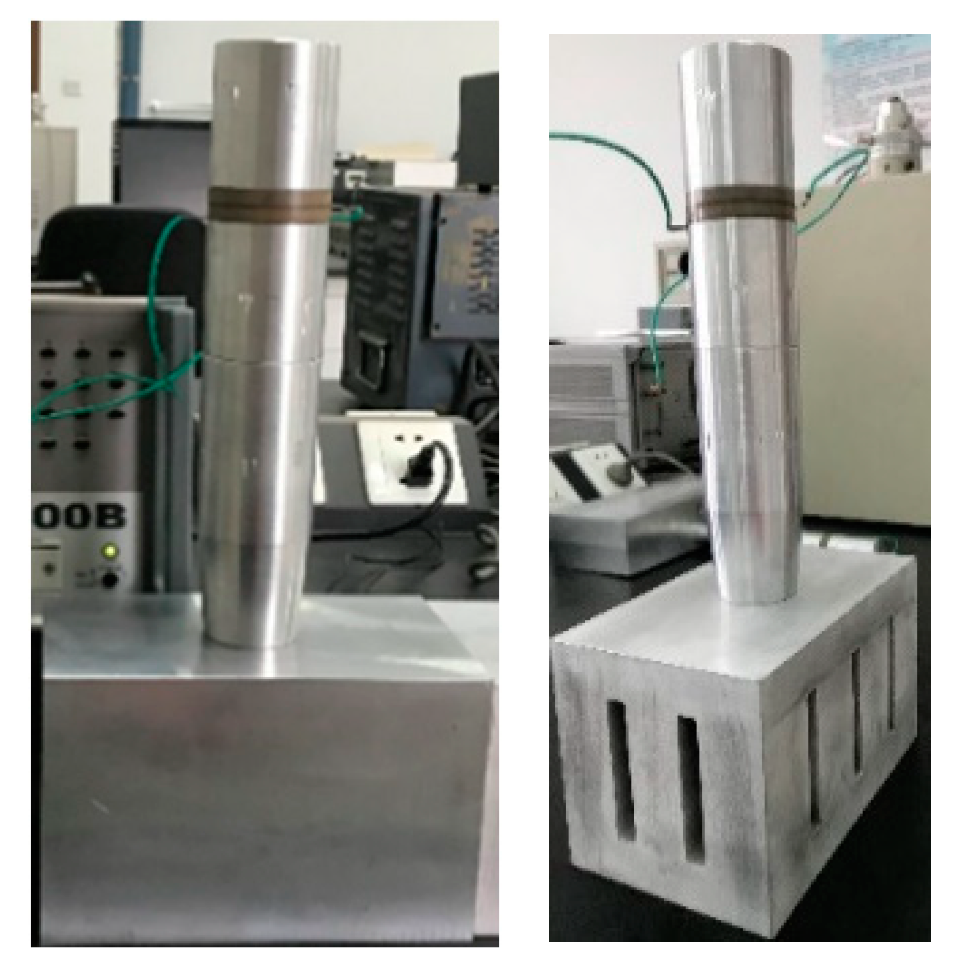
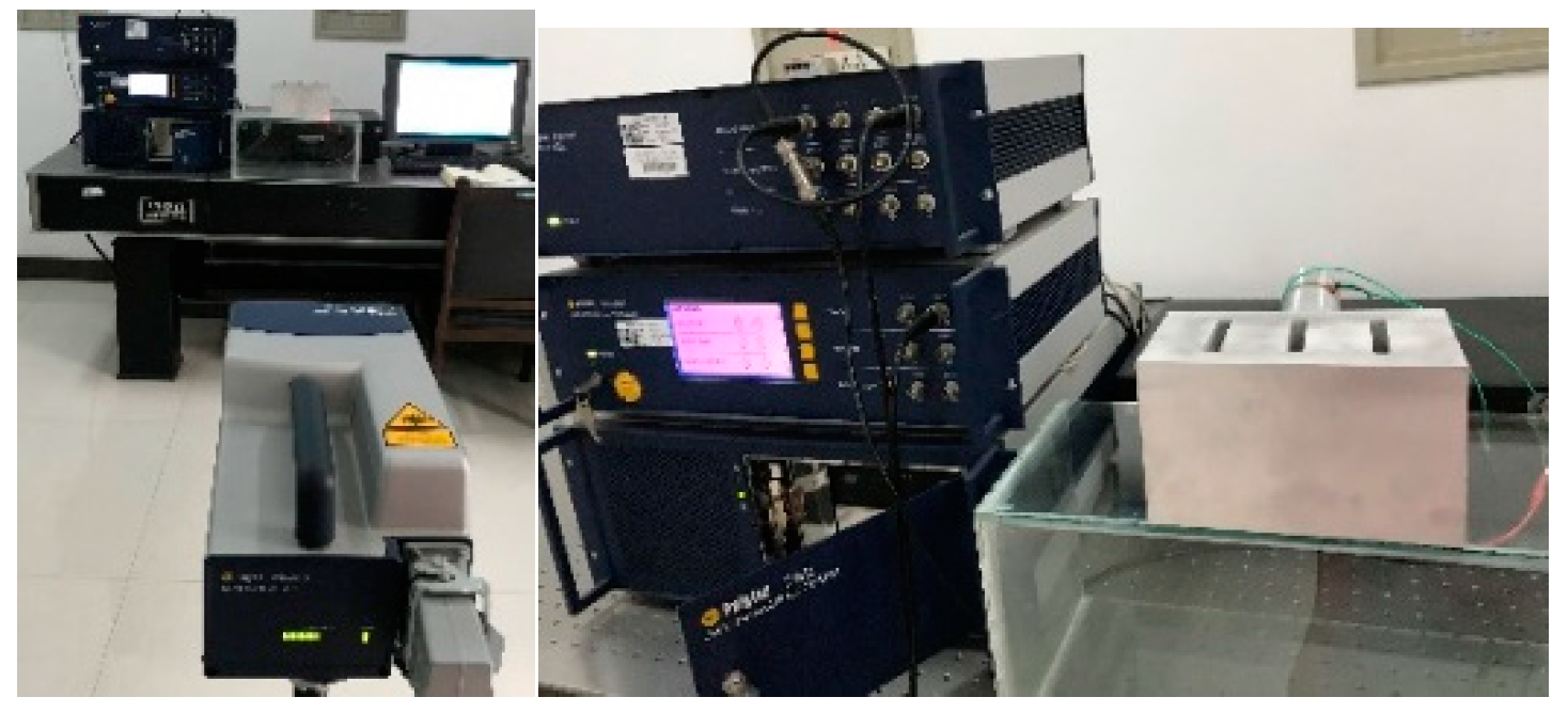
5. Experimental Validation

In order to verify the correctness of the numerical simulation, two sets of large-scale ultrasonic plastic welding vibration systems (Figure 15) were processed, and their input electrical impedance and vibration displacement distribution are tested experimentally. The parameters of material and structure used in processing system and simulation are the same.

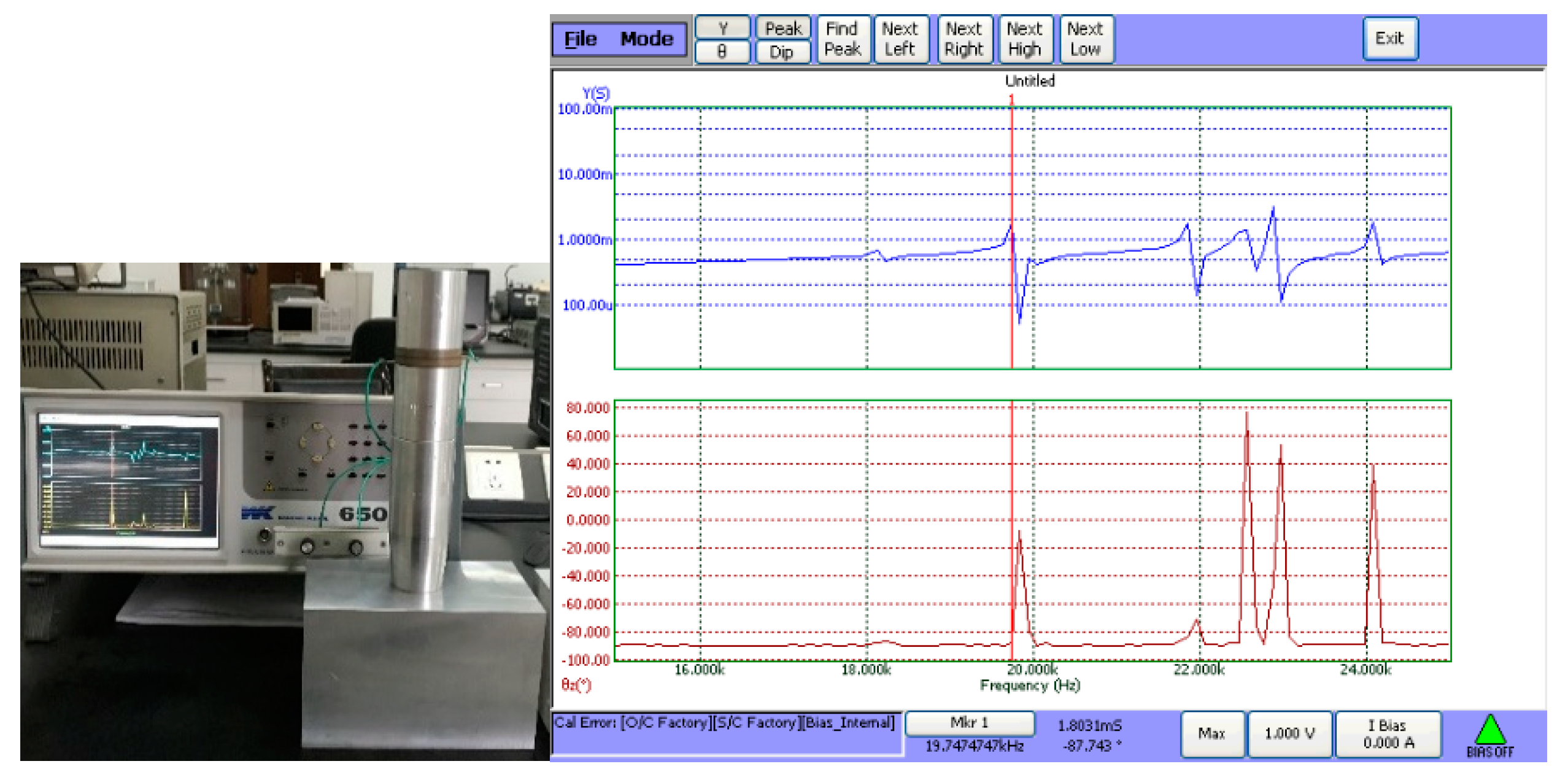
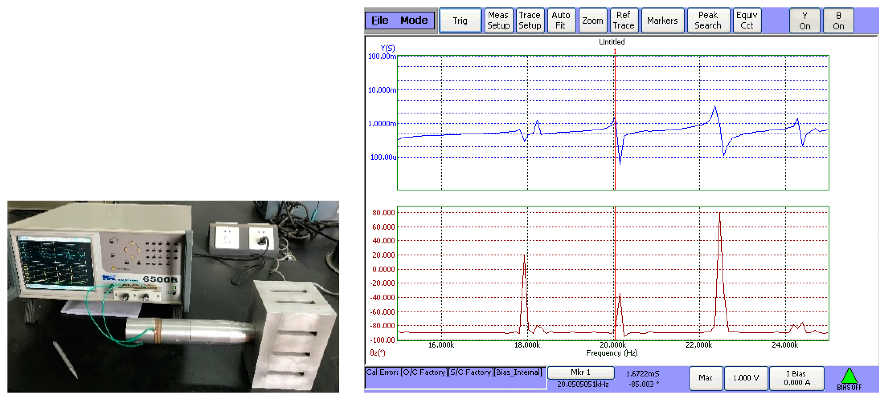
5.1. Measurement and Verification of Input Electric Impedance and Resonance Frequency

The vibration modal pattern and admittance curve of the large-scale ultrasonic plastic welding vibration system without slots obtained by COMSOL multiphysics simulation are shown in Figure 16. It can be seen from Figure 16 that the longitudinal resonance frequency of the large-scale ultrasonic plastic welding vibration system without slots is about 19.931 kHz. In order to verify the accuracy of the simulation values, the 6500b precision impedance analyzer shown in Figure 17 is used to test the admittance of the large-scale ultrasonic plastic welding vibration system without slots, and the test results are shown in Figure 17. According to the admittance curve, its longitudinal resonance frequency is 19.747 kHz, and the error is 0.931%. The two results are in good agreement and can meet the requirements of engineering applications.
The vibration modal and admittance curve of the large-scale three-dimensional ultrasonic plastic welding vibration system based on a quasi-periodic phononic crystal structure are shown in Figure 18, which are obtained by Comsol Multiphysics (COMSOL Multiphysics 5.4, Comsol, Stockholm, Sweden). It can be seen from Figure 18 that the longitudinal resonance frequency of the system is about 20.290 kHz. Then, the admittance curve of the large-scale three-dimensional ultrasonic plastic welding vibration system based on a quasi-periodic phononic crystal structure is measured using the 6500B precision impedance analyzer and shown in Figure 19. It can be seen from Figure 19 that the longitudinal resonance frequency of the system based on the quasi-periodic phononic crystal structure is 20.051 kHz, with an error of 1.192%. The two measurement results are also in good agreement and can also meet the requirements of engineering application.

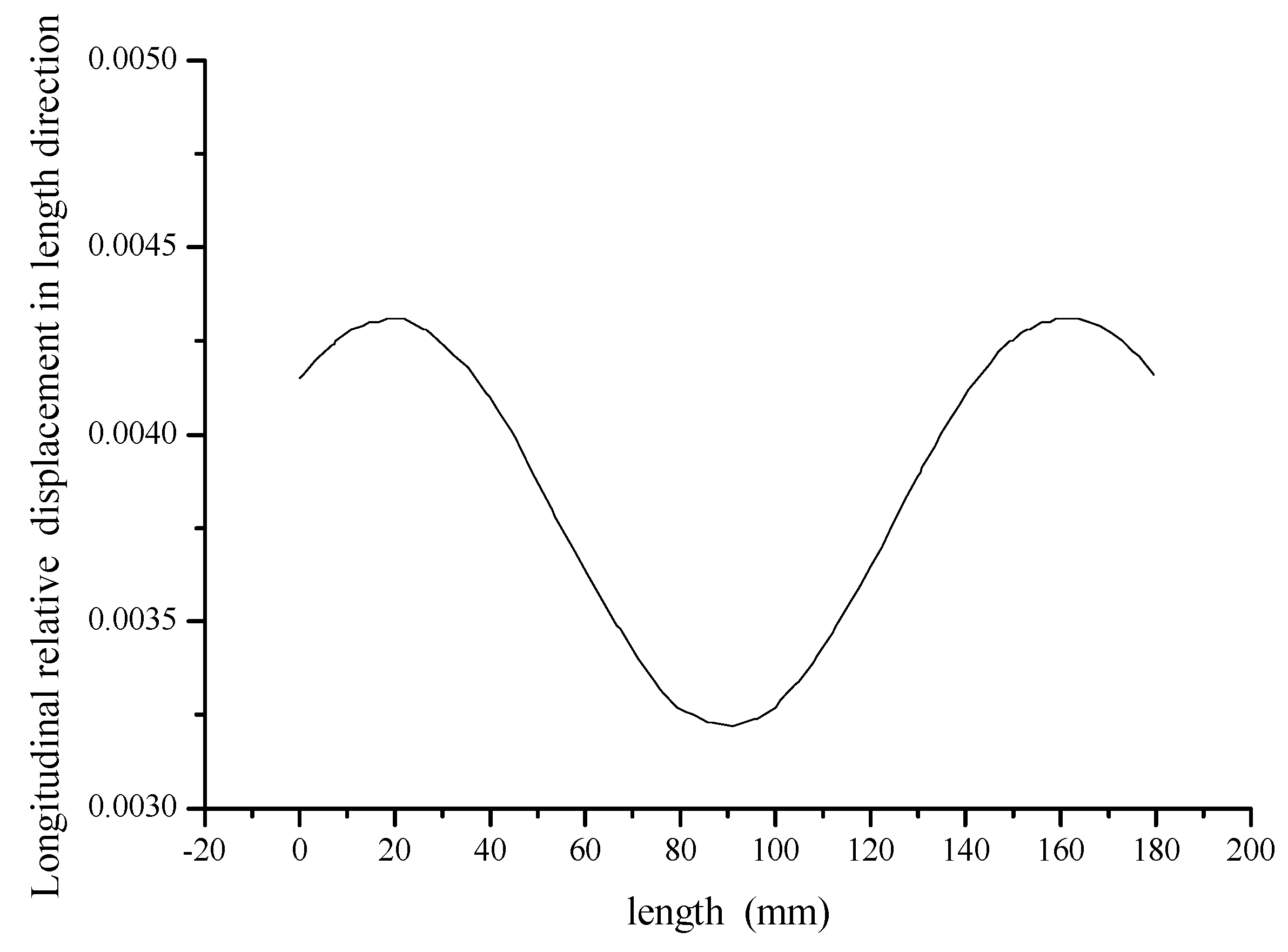
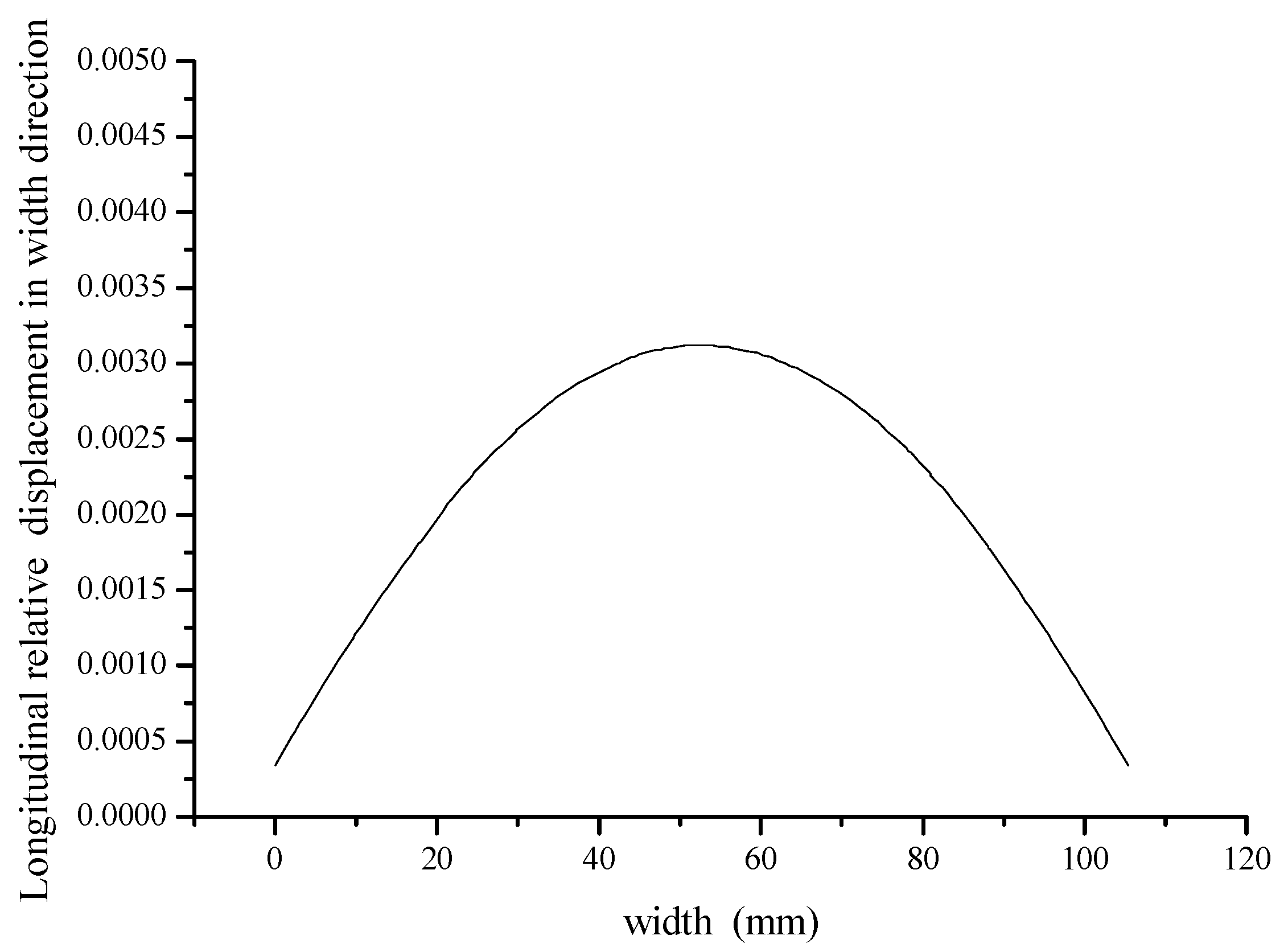
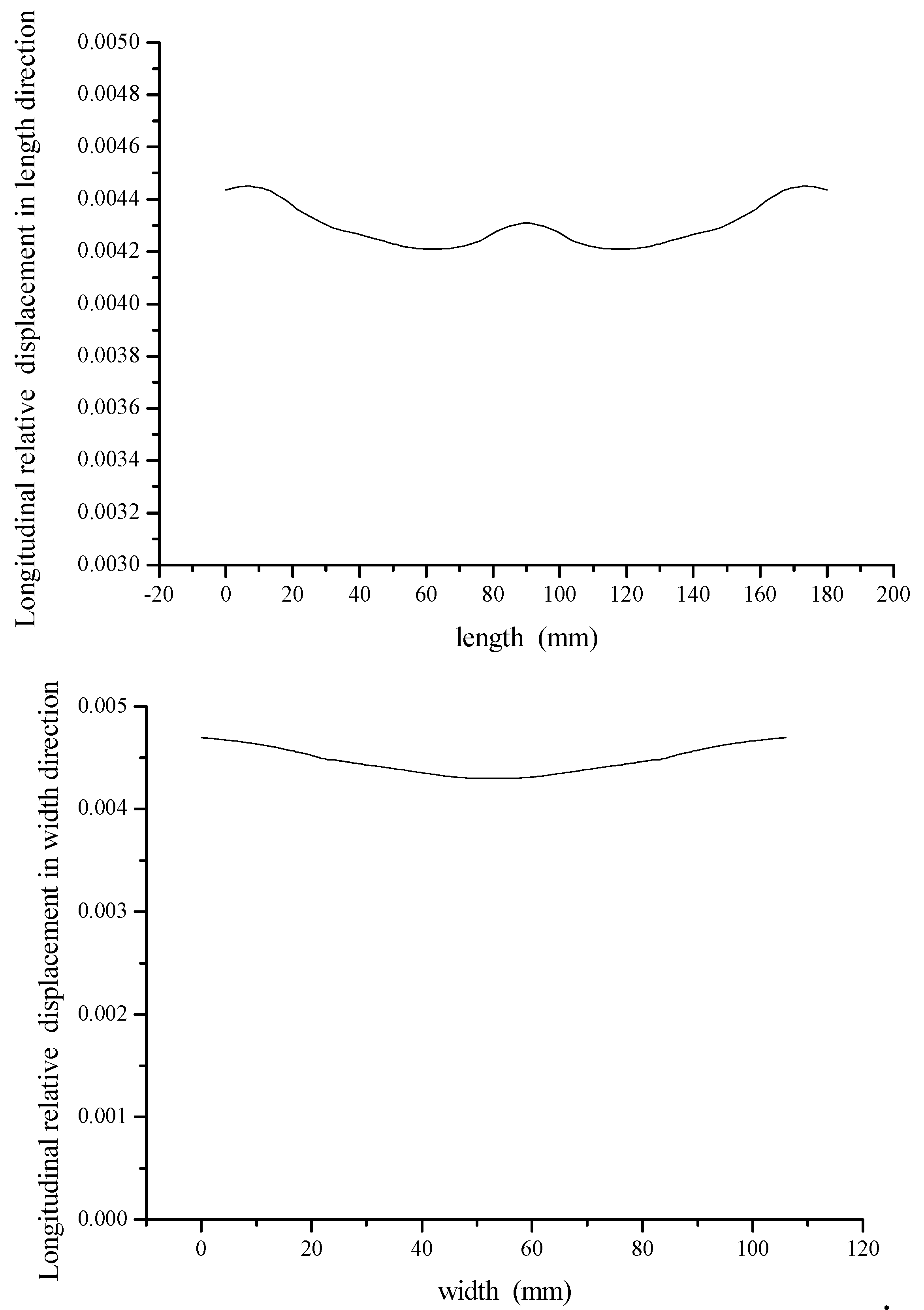
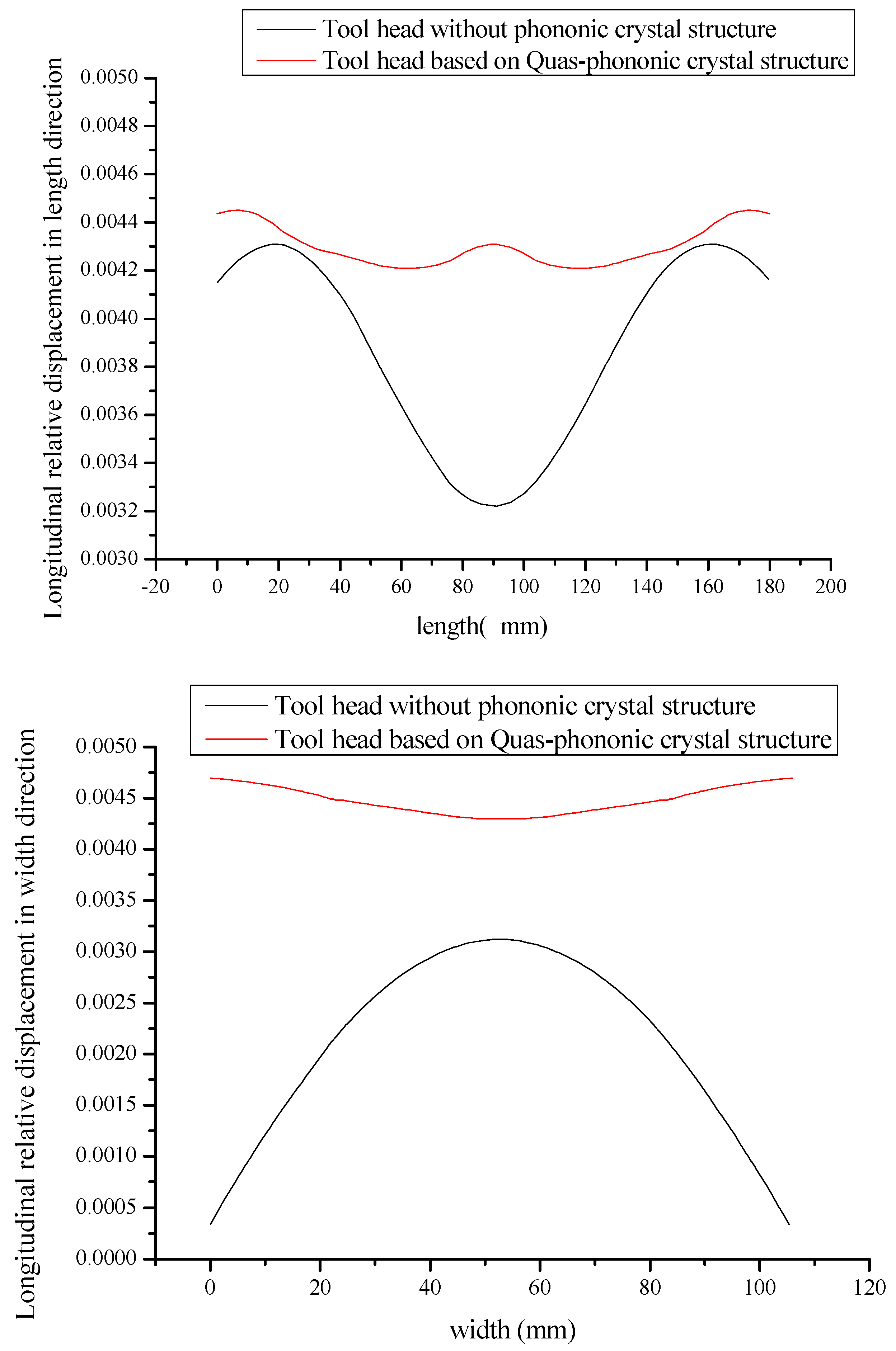
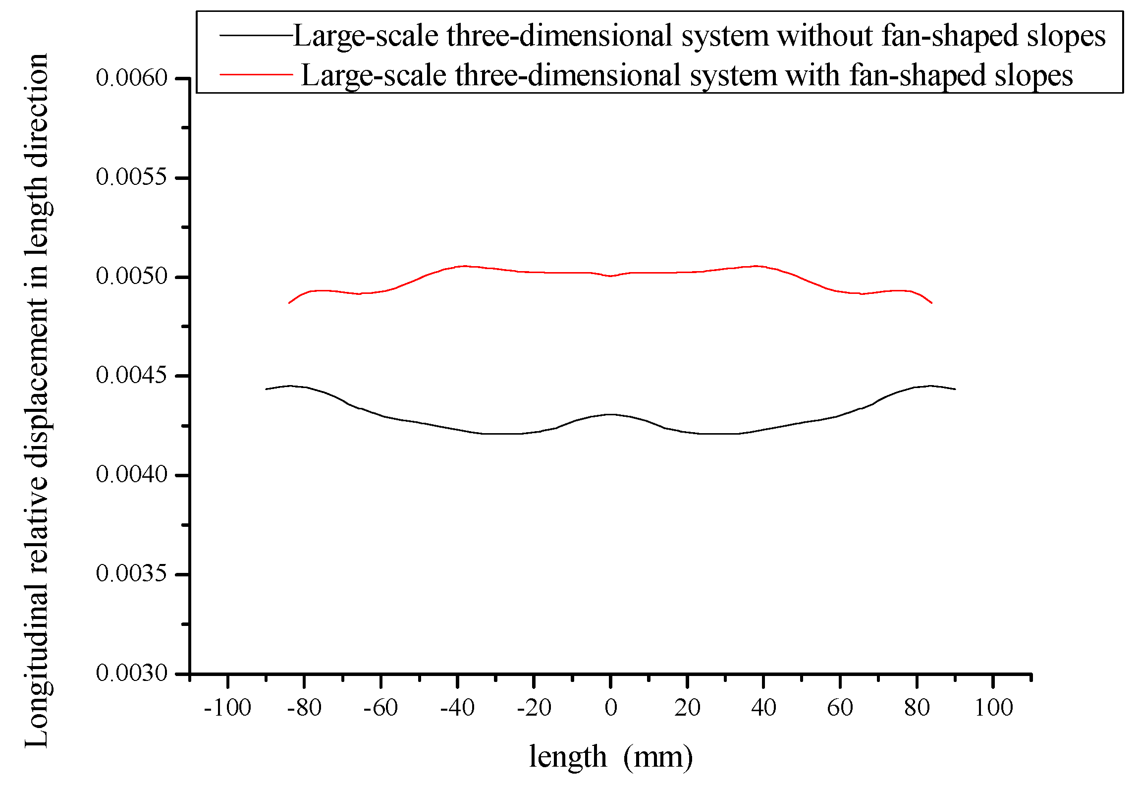
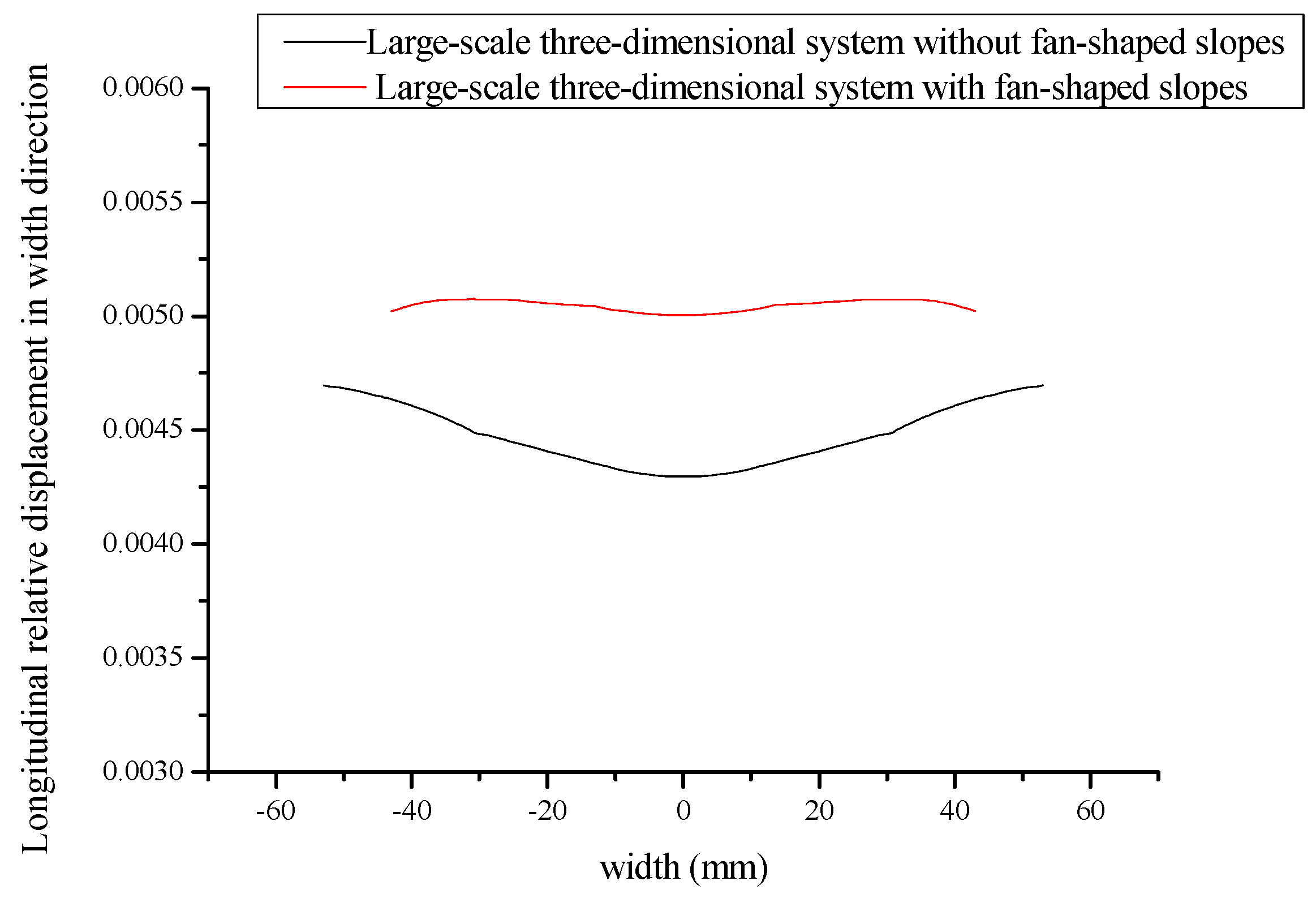
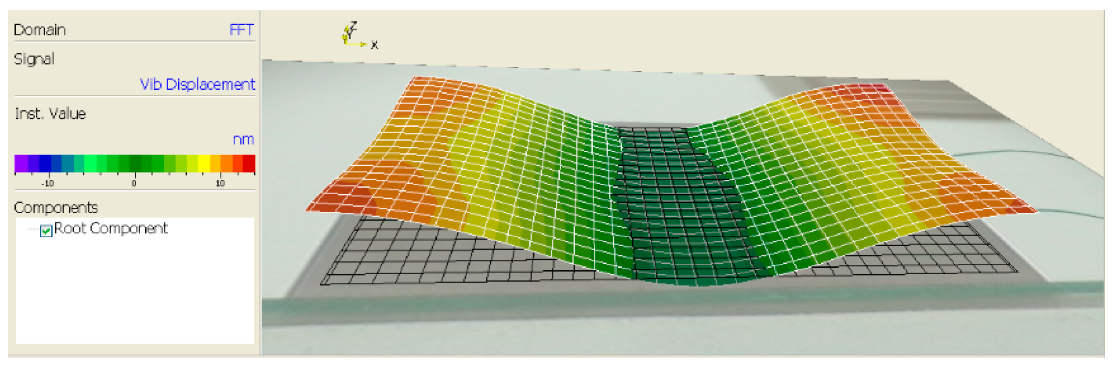
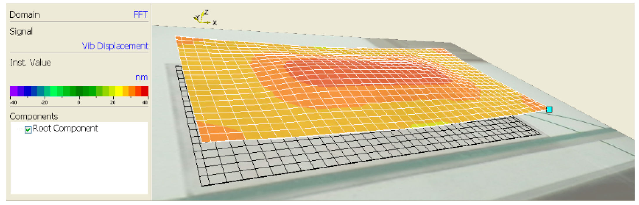
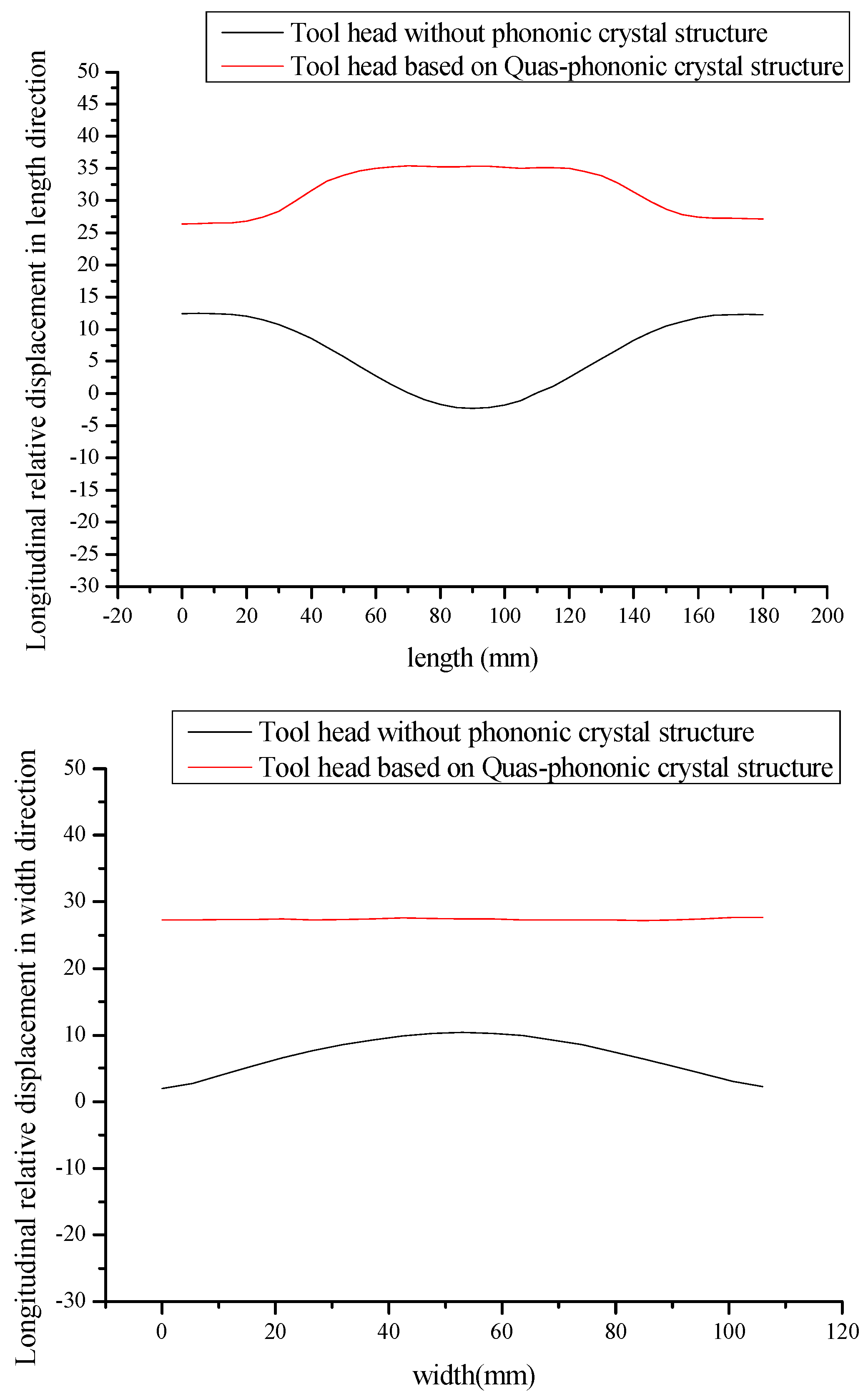
5.2. Measurement and Verification of Amplitude Distribution of Tool Head

In order to further verify the simulation results of the amplitude distribution of the tool head, the PSV-400 full field scanning laser vibration measurement system shown in Figure 20 is used to measure the amplitude distribution of the unslotted system and the system based on the quasi-periodic phononic crystal structure. The measurement results are shown in Figure 21 and Figure 22. In order to analyze the amplitude distribution comparison between the two systems more clearly and intuitively, the amplitude distribution data of the radiation surface measured by the experiment is used to draw the amplitude distribution comparison diagram that is shown in Figure 23.
It can be seen from Figure 21, Figure 22 and Figure 23 that the amplitude distribution of the large-scale three-dimensional ultrasonic vibration system based on the quasi-periodic phononic crystal structure is more uniform. In the X direction, the uniformity of the amplitude distribution of the system without slots is only 7.49%, while the uniformity of the amplitude distribution based on the quasi periodic phononic crystal structure is 74.6%; In the Y direction, the amplitude distribution uniformity of the system without slots is 19.3%, while the system based on the quasi-periodic phononic crystal structure is 90.5%. In addition, the amplitude of the system based on the quasi-periodic phononic crystal structure in the X and Y directions is greatly improved. The experimental results show that the optimization of the vibration system is effective.

6. Conclusions

In this paper, a large-scale three-dimensional ultrasonic plastic welding vibration system based on the quasi-periodic phononic crystal structure is studied in which the transducer, horn, and large-scale three-dimensional tool head of the vibration system are optimized. By processing the periodic slots of the quasi-periodic phononic crystal structure and fan-shaped slopes on the large-scale three-dimensional tool head, the lateral coupling vibration of the tool head in the X and Y directions is effectively suppressed, so that the longitudinal amplitude distribution of the welding surface is more uniform. Meanwhile, the longitudinal vibration amplitude gain is also improved by optimizing the structural parameters of the horn and the tool head. Simulation and experimental results show that the optimization of the vibration system of large-scale three-dimensional ultrasonic plastic welding is effective, which can improve the welding quality and work efficiency of the system.

Author Contributions

Conceptualization and supervision, J.L. and S.L.; methodology, J.L.; validation, J.L.; data curation, J.L.; writing—review and editing; S.L. All authors have read and agreed to the published version of the manuscript.

Funding

This research was funded by the National Natural Science Foundation of China, Grant Nos. 11674206, 11874253 and 11964040.

Acknowledgments

The authors would like to thank the National Natural Science Foundation of China.

Conflicts of Interest

The authors declare no conflict of interest.

References

  1. Lin, S.Y.; Zhang, F.C. Cube coupling vibration of rectangular hexahedron with ultrasonic frequency. J. Acoust. 1991, 3, 91–97. [Google Scholar]
  2. Lin, S.Y.; Zhang, F.C. A Study of Coupled and Lateral Vibration in High Power Ultrasonic Vibrating. Acta Acust. United Acust. 1993, 79, 274–277. [Google Scholar]
  3. Koike, Y.; Ueha, S. A finite-element analysis of transient vibration of an ultrasonic welding tool. Jpn. J. Appl. Phys. 1993, 32, 2426–2429. [Google Scholar] [CrossRef]
  4. Andrea, C.; Margaret, L. Enhanced vibration performance of ultrasonic block horns. Ultrasonics 2002, 40, 365–369. [Google Scholar]
  5. Mori, E.; Itoh, K.; Imamura, A. Analysis of a short column vibrator by apparent elasticity method and its application. In Proceedings of the Ultrasonics International Conference, Sendai, Japan, 5–8 October 1997; pp. 262–266. [Google Scholar]
  6. Zhou, G.P.; Liang, M.J.; Wang, X. Study on large-scale ultrasonic vibrating body. Acoust. Tech. 2004, 3, 183–195. [Google Scholar]
  7. Liang, M.J.; Zhou, G.P.; Wang, J.X. Vibration analysis of long strip ultrasonic plastic welding mode. J. Shenzhen Polytech. 2003, 4, 5–8. [Google Scholar]
  8. Liang, Z.F.; Zhou, G.P.; Mo, X.P. A new design method of large-scale long strip ultrasonic plastic welding slotted welding head. Mech. Sci. Tech. 2008, 3, 334–337. [Google Scholar]
  9. Liang, Z.F.; Zhou, G.P.; Mo, X.P. Concise design of long strip ultrasonic plastic welding joint. Acoust. Tech. 2008, 1, 134–137. [Google Scholar]
  10. Liang, Z.F.; Zhou, G.P.; Zhang, Y.H. Optimization design of large-scale long strip ultrasonic plastic welding head. Mech. Des. Manu. 2009, 2, 235–236. [Google Scholar]
  11. Zhao, T.T.; Lin, S.Y.; Duan, Y.L. The suppression of the lateral vibration of ultrasonic plastic welding tools by the phonon like crystal structure. Acta Phys. Sin. 2018, 67, 280–285. [Google Scholar]
  12. Wang, S.; Lin, S.Y. Optimization design of large size sandwich transducer based on two-dimensional phononic crystal. Acta Phys. Sin. 2019, 68, 024303-1–024303-6. [Google Scholar]
  13. Wang, S.; Lin, S.Y. Optimization on ultrasonic plastic welding systems based on two-dimensional phononic crystal. Ultrasonics 2019, 99, 1–6. [Google Scholar] [CrossRef] [PubMed]
  14. O’Shea, K. Enhanced vibration control of ultrasonic tooling using finite element analysis. Vib. Anal. Anal. Comput. 1991, E37, 259–265. [Google Scholar]
  15. Chen, X.M. Study on ultrasonic coupling vibration of large-scale rectangular vibrating body[D]. Shaanxi Norm. Univ. 2008. [Google Scholar]
  16. Wen, X.S. Phononic Crystal; National Defense Industry Press: Beijing, China, 2009; Volume 1, pp. 10–12. [Google Scholar]
  17. Vasseur, J.O.; deymier, P.A.; Djafari-Rouhani, B.; Pennec, Y. Absolute forbidden bands and growing in two-dimensional photovoltaic crystal plates. Phys. Rev. B Cond. Mater. 2008, 20, 439–446. [Google Scholar]
  18. Liang, T.L. Study on Band Gap Characteristics of Two-Dimensional Quasi Periodic Phononic Crystals; Beijing Jiaotong University: Beijing, China, 2012. [Google Scholar]
  19. Xian, X.J.; Lin, S.Y. Study on the compound multifrequency ultrasonic transducer in flexural vibration. Ultrasonics 2008, 7, 202–208. [Google Scholar] [CrossRef] [PubMed]
  20. Zhao, B.; Bie, W.B.; Wang, X.B.; Chen, F.; Chang, B.Q. Design and experimental investigation on longitudinal-torsional composite horn considering the incident angle of ultrasonic wave. Int. J. Adv. Manu. Tech. 2019, 105, 1–4. [Google Scholar] [CrossRef]
  21. Morozov, E.V.; Lopatin, A.V.; Taygin, V.B. Design, analysis, manufacture and testing of composite corrugated horn for the spacecraft antenna system. Comput. Struct. 2016, 12, 136. [Google Scholar] [CrossRef]
  22. Zheng, X.; Liu, Y.; Luo, A.; Liu, C.S. Realization of longitudinal torsional composite vibration of conical composite horn. Mech. Sci. Tech. 2013, 32, 1186–1189. [Google Scholar]
  23. Liu, Z.X.; Liu, Y.Q.; Bai, Y.B.; Su, B.L. Optimal design of stepped-cone ultrasonic horn with center hole. Manufac. Auto. 2018, 40, 42–45. [Google Scholar]
Figure 1. Schematic diagram of a large-scale three-dimensional ultrasonic plastic welding vibration system.
Crystals 10 00021 g001
Figure 2. Modal shape of a large-scale three-dimensional ultrasonic plastic welding vibration system.
Crystals 10 00021 g002
Figure 3. Longitudinal displacement distribution of welding surface in the X direction.
Crystals 10 00021 g003
Figure 4. Longitudinal displacement distribution of welding surface in the Y direction.
Crystals 10 00021 g004
Figure 5. Dimension diagram of the ultrasonic transducer.
Crystals 10 00021 g005
Figure 6. Dimension diagram of the composite horn.
Crystals 10 00021 g006
Figure 7. Schematic and dimensional drawing of a large-scale three-dimensional tool head based on a quasi-periodic phononic crystal structure: (a) structure diagram of the tool head; (b) dimensional drawing of each part of the tool head on the XZ surface; (c) dimensional drawing of each part of the tool head on the YZ surface.
Crystals 10 00021 g007
Figure 8. Acceleration response curves along the tool head length X and width Y based on a quasi-periodic phonon crystal structure.
Crystals 10 00021 g008
Figure 9. Structure, vibration pattern and vibrational displacement distribution of large-scale three-dimensional ultrasonic plastic welding vibration system based on a quasi-periodic phononic crystal structure.
Crystals 10 00021 g009
Figure 10. Longitudinal displacement distribution of X and Y directions of the welding head of the tool head based on a quasi-periodic phononic crystal structure.
Crystals 10 00021 g010
Figure 11. Comparison of longitudinal displacement distribution of system based on a quasi-periodic phononic crystal structure and system without a quasi-periodic phononic crystal structure n length X and width Y direction.
Crystals 10 00021 g011
Figure 12. Structure and each part’s dimension diagram of optimized tool head: (a) structure diagram of the tool head; (b) dimensional drawing of each part of the tool head on the XZ surface; (c) dimensional drawing of each part of the tool head on the YZ surface.
Crystals 10 00021 g012
Figure 13. Optimized structure and vibration modal diagram of a large-scale three-dimensional ultrasound plastic welding vibration system.
Crystals 10 00021 g013
Figure 14. Comparison of the longitudinal displacement distribution in X and Y directions of systems with fan-shaped slopes and without fan-shaped slopes.
Crystals 10 00021 g014aCrystals 10 00021 g014b
Figure 15. Physical picture of large-scale three-dimensional ultrasonic plastic welding vibration system without slots and based on a quasi-periodic phononic crystal structure.
Crystals 10 00021 g015
Figure 16. Vibration mode and simulation admittance curve of an unslotted large-scale three-dimensional ultrasonic plastic welding vibration system.
Crystals 10 00021 g016
Figure 17. Frequency response test device and frequency curve of the admittance of the system without slotting.
Crystals 10 00021 g017
Figure 18. Vibration mode and simulation admittance curve of a large-scale three-dimensional ultrasonic plastic welding vibration system based on a quasi-periodic phononic crystal structure.
Crystals 10 00021 g018
Figure 19. Frequency response test device and frequency curve of the admittance of the slotted system.
Crystals 10 00021 g019
Figure 20. Experimental test device for amplitude distribution measurement (PSV-400 full field scanning laser vibration measurement system).
Crystals 10 00021 g020
Figure 21. Measurement results of the amplitude distribution of the tool head in the vibration system of large-scale ultrasonic plastic welding without slotting.
Crystals 10 00021 g021
Figure 22. Measurement results of amplitude distribution of the tool head of large-scale three-dimensional ultrasonic plastic welding vibration system based on a quasi-periodic phononic crystal structure.
Crystals 10 00021 g022
Figure 23. Measurement results comparison of amplitude distribution in the X and Y directions between the system without slotting and the system based on a quasi-periodic phononic crystal structure.
Crystals 10 00021 g023

