Article

Control of Microstructure for Co-Cr-Mo Fibers Fabricated by Unidirectional Solidification

1
Institute for Material Research, Tohoku University, 2-1-1, Katahira, Aoba-ku, Sendai, Miyagi 980-8577, Japan
2
New Industry Creation Hatchery Center (NICHe), Tohoku University, 6-6-10, Aoba, Aramaki, Aoba-ku, Sendai, Miyagi 980-8579, Japan
3
C&A Corporation, 6-6-40, Aoba, Aramaki, Aoba-ku, Sendai, Miyagi 980-8579, Japan
*
Author to whom correspondence should be addressed.
Crystals 2020, 10(1), 11; https://doi.org/10.3390/cryst10010011
Submission received: 28 November 2019 / Revised: 22 December 2019 / Accepted: 24 December 2019 / Published: 26 December 2019
(This article belongs to the Special Issue Mechanical and Microstructural Characterization of Metals and Alloys)

Abstract

:
Co-Cr-Mo alloy fibers of 2 mm in diameter were fabricated from the melt at 1, 2, and 5 mm/min growth rates by unidirectional solidification using an alloy-micro-pulling-down (A-µ-PD) method to control the microstructure. All elements, Co, Cr, and Mo, were distributed in stripes elongated along the growth direction due to constitutional undercooling. Both Co-Cr-Mo fibers fabricated at 2 and 5 mm/min growth rates were composed of the γ phase with a face-centered cubic structure (fcc-γ phase) and ε-phase with a hexagonal close-packed structure (hcp-ε phase), and the ratio of the fcc-γ phase in the fiber fabricated at 5 mm/min growth rate was higher than that in the fiber fabricated at 2 mm/min. The results suggest that a faster growth rate increases the ratio of the fcc-γ phase in the Co-Cr-Mo fiber fabricated by unidirectional solidification.

1. Introduction

Co-Cr-Mo alloys have been used in various applications of biomaterials such as dental implants, hip and knee joints, and stents because of their excellent mechanical properties, resistance to oxidation, and biocompatibility [1,2,3,4,5,6,7,8,9]. However, the hardness of Co-Cr-Mo alloys causes poor workability in the forming processes and limits the ductility. The complicated forming processes, including casting, cutting, and rolling, increase the manufacturing cost of a Co-Cr-Mo alloy element for such applications [10]. Therefore, near-net-shape manufacturing processes such as selective laser melting (SLM) and electron beam melting (EBM) processes have been developed for Co-Cr-Mo alloys in previous studies [10,11,12,13]. Near-net-shape manufacturing processes can fabricate alloy products with a complicated shape directly. However, the manufacturing costs of these processes are relatively high compared to existing molding processes due to the low mass-productivity and the preparation of nano-powder with uniform particle size.
Previously, we developed an alloy-micro-pulling-down (A-µ-PD) method, which could fabricate a fiber from the melt of metal and alloy directly [14]. The A-µ-PD method is based on the µ-PD method, which can grow inorganic single crystals from the melt, and various functional single crystals have been developed [15,16,17,18]. The A-μ-PD method can fabricate metal and alloy fibers with poor workability and a high melting point, and the diameter of the fabricated fiber can be controlled with accuracy to the submicron level [19]. In our previous reports, noble metal and alloy fibers such as iridium (Ir), ruthenium (Ru), platinum (Pt) and their alloys could be fabricated by the A-µ-PD method [14,19,20].
In addition, we also fabricated Co-Cr-Mo alloy fibers by the A-μ-PD method, and Co-Cr-Mo fibers of 2 mm in diameter could be fabricated at 0.1, 0.3, and 0.5 mm/min growth rates [21]. In the previous study, the mechanical properties of the fibers fabricated at 0.1 and 0.3 mm/min growth rates were completely different from the fiber fabricated at 0.5 mm/min. The Co-Cr-Mo fibers fabricated at 0.1 and 0.3 mm/min growth rates were composed of only ε-phase with hexagonal close-packed structure (hcp-ε phase). On the other hand, there was γ phase with face-centered cubic structure (fcc-γ phase) in addition to hcp-ε phase in the fiber fabricated at a 0.5 mm/min growth rate. The mechanical properties of the Co-Cr-Mo alloy are sensitive to its microstructure [22,23,24,25], and the fcc-γ phase has better mechanical properties and is stable at high temperature (>1173 K) while the hcp-ε phase is stable at room temperature. The fcc-γ to hcp-ε transformation can be induced by additive materials and heat treatment [26,27,28,29,30,31,32,33]. For example, nickel and nitrogen are used as additive materials to stabilize the fcc-γ phase [26,27,28,29]. In addition, the fcc-γ phase could be retained by water quenching from the higher temperature than the phase transition from the fcc-γ phase to the ε-phase (~1173 K) [26,30,31,32,33]. Therefore, the growth rate could control the microstructure of the Co-Cr-Mo fiber using the A-μ-PD method. In this study, we tried to fabricate Co-Cr-Mo fibers at a faster growth rate by using the A-µ-PD method to increase the ratio of the fcc-γ phase.

2. Materials and Methods

Co-Cr-Mo alloy fibers were fabricated by the A-µ-PD method using a radio-frequency (RF) induction-heating high-vacuum chamber and pinch roller. Starting materials Co, Cr, and Mo powders (>99.9% purity) were mixed as a nominal composition of Co-Cr-Mo 28:6:1(wt%). Mixed powders were pelletized by an arc melting furnace under Ar atmosphere with a titanium getter, and Co-Cr-Mo pellets of 20 mm in diameter were obtained. The pellets were set into an α-Al2O3 crucible with a φ2 mm hole at the center of the bottom, and the crucible was placed in the center of the RF induction coil. After vacuuming in the chamber by a rotary pump, Ar or Ar + 3%H2 gas was introduced into the chamber up to atmospheric air pressure. The pellets in the crucible were directly heated by the RF induction heating up to the melting point. After the pellets were completely melted, a Co-Cr-Mo fiber was fabricated using a φ1 mm Ir fiber as a seed. During the fabrication, the fiber was pulled down using a pinch roller at 2 and 5 mm/min growth rates. The liquid–solid interface around the bottom of the crucible was observed by a charge-coupled device (CCD) camera during the fabrication of the Co-Cr-Mo fiber. After the fabrication, the fiber was cooled for 2 hours to room temperature.

3. Experimental Procedure

Observations of microstructures and chemical composition analyses of the fabricated Co-Cr-Mo fibers were performed. As-fabricated Co-Cr-Mo fibers were cut perpendicular to the growth direction, and specimens were prepared to observe the microstructure of cross-sectional planes. Cut planes of the specimens were mechanically polished parallel to the growth direction using sandpaper and lapping film sheets, and polished surfaces were treated by a cross-section polisher (CP) (JEOL, Tokyo, Japan) using Ar+ ion accelerated at 5 kV. Microstructures on the treated surfaces were observed by a field-emission scanning electron microscope (FE-SEM) (JSM7800-F, JEOL, Tokyo, Japan) equipped with an energy-dispersive X-ray spectrometer (EDX) (JEOL, Tokyo, Japan) and electron backscattering diffraction (EBSD) (JEOL, Tokyo, Japan). Chemical composition analysis was performed by the EDX, and element mappings and distributions along the growth direction for the Co-Cr-Mo fibers were obtained. Phase maps of the treated surfaces of the Co-Cr-Mo fibers were observed by EBSD. Aztec software was used for measurement and analysis, and all analyses were operated at an acceleration voltage of 15 kV.

4. Results and Discussion

First, fabrication of Co-Cr-Mo fibers was attempted using the A-μ-PD method under the Ar atmosphere at a 2 mm/min growth rate. After melting the pellet, the Ir seed fiber was touched to the melt in the crucible, and a Co-Cr-Mo fiber was fabricated through the hole of the crucible. Figure 1a shows the liquid–solid interface during fabrication of the Co-Cr-Mo fiber by the A-μ-PD method. The liquid–solid interface was located at the bottom of the crucible during fabrication, and the diameter of the fabricated fiber could be controlled by the hole of the crucible. As a result, a Co-Cr-Mo fiber of 2 mm in diameter and ~150 mm in length was obtained as shown in Figure 1b. However, slight oxidation was observed on the surface and inside of the fabricated fiber. Oxidized phases with the dendrite structure were observed in the back-scattering electron (BSE) image on the polished surface parallel to the growth direction for the fiber fabricated under Ar atmosphere as shown in Figure 2a. The results of the element mapping by the EDX revealed that the oxidized phase was a chromium oxide. Therefore, in the next step, the fiber fabrication was performed under Ar + 3%H2 mixed gas atmosphere to suppress the oxidation of the Co-Cr-Mo fibers. Figure 1c shows the Co-Cr-Mo fibers fabricated under Ar + 3%H2 atmosphere at 1, 2, and 5 mm/min growth rates. These fibers also have 2 mm diameters and are approximately 150 mm in length. There was no chromium oxide phase in the BSE image and element mappings of the fiber fabricated under Ar + 3%H2 atmosphere as shown in Figure 2b because of the suppression of oxidization reaction by fabrication under reducing atmosphere.
Figure 3 shows secondary scanning electron (SE) images on the CP treated surfaces parallel to the growth direction for the Co-Cr-Mo fibers fabricated at 2 and 5 mm/min growth rates. Grain boundaries can be observed in the images of the CP treated surface of the Co-Cr-Mo fibers. Co-Cr-Mo fibers fabricated at both 2 and 5 mm/min growth rates were composed of micrometer order grains elongated along the growth direction. There is no clear difference between the microstructures of the fibers fabricated at 2 and 5 mm/min growth rates in the SE images.
Element mappings on the CP treated surface parallel to the growth direction for the Co-Cr-Mo fibers fabricated under Ar + 3%H2 atmosphere were obtained by the EDX. Figure 4a shows the element mapping of Mo, which was distributed in stripes elongated along the growth direction in the fibers fabricated at 2 and 5 mm/min growth rates, and a similar tendency was observed in the EDX mappings of Co and Cr. Figure 4b shows the concentration distributions of Co, Cr, and Mo in the direction perpendicular to the growth direction, while the line measured is indicated by the black arrow in Figure 4a. All elements periodically varied perpendicular to the growth direction, and the variation value of C/C0 (C: actual concentration in the fiber, C0: concentration in the melt) for Mo was larger than those for Co and Cr. In addition, the cycle of variation in the C/C0 of the fiber fabricated at 5 mm/min growth rate was shorter than that in the fiber fabricated at 2 mm/min. The results suggest that the variation of each element in the fibers is attributable to the fluctuation of the liquid–solid interface during fiber fabrication due to constitutional undercooling. The increase and decrease in the concentration variations of Mo and Co were opposite to that of Cr, suggesting that the fibers were composed of Cr-rich and -poor phases.
Phase maps on the treated surfaces of the Co-Cr-Mo fibers were observed by EBSD as shown in Figure 5. The Co-Cr-Mo fibers fabricated at 2 and 5 mm/min growth rates included both fcc-γ and hcp-ε phases, while the Co-Cr-Mo fiber fabricated at 1 mm/min growth rate was almost entirely composed of the hcp-ε phase. In our previous report [12], the Co-Cr-Mo fiber fabricated at 0.5 mm/min growth rate included the fcc-γ phase in addition to the hcp-ε phase, and generation of the fcc-γ phase was observed between 0.3 and 0.5 mm/min growth rates. The difference in growth rate at the start point of the fcc-γ phase generation between the results of previous studies and this one is attributable to the difference in temperature gradient along the growth direction, which can affect the cooling rate of Co-Cr-Mo fiber after the fiber fabrication.
The ratios of the fcc-γ and hcp-ε phases in the Co-Cr-Mo fibers were estimated according to the results of phase maps (Table 1). Zero solution refers to the regions where the phase could not be identified due to the poor surface state. Ratios of the fcc-γ phase in the fibers fabricated at 1, 2, and 5 mm/min growth rates were 0.01%, 23.49%. and 36.51%, respectively. The results revealed that a faster growth rate increases the ratio of the fcc-γ phase in the fiber fabricated by unidirectional solidification.

5. Conclusions

φ2 mm Co-Cr-Mo fibers of approximately 150 mm in length were fabricated from the melt by the A-μ-PD method at 1, 2, and 5 mm/min growth rates. Fabrication under Ar + 3%H2 atmosphere could suppress the generation of chromium oxide in the fiber, while chromium oxide phases with dendrite structure were observed in the fiber fabricated under Ar. Grain boundaries could be observed in the SE images of the CP treated surfaces of the Co-Cr-Mo fibers. The Co-Cr-Mo fibers fabricated at 2 and 5 mm/min growth rates were composed of micrometer order grains elongated along the growth direction. Each element was distributed in stripes elongated along the growth direction in the fibers, and the variation of each element in the direction perpendicular to growth direction is attributable to the fluctuation of the liquid–solid interface during fiber fabrication due to the constitutional undercooling. The increase and decrease in the concentration variation of each element suggests that the fibers were composed of Cr-rich and -poor phases. Ratios of the fcc-γ phase in the fibers fabricated at 1 and 5 mm/min growth rates were 0.01% and 36.51%, respectively. Therefore, the ratio of the fcc-γ phase in the fiber fabricated by unidirectional solidification could be increased by a faster growth rate. The control of microstructure by the growth rate without doping and post-annealing is a great advantage compared with the conventional manufacturing methods.

Author Contributions

Conceptualization, S.A., Y.Y and T.N.; methodology, S.A., Y.Y. and T.N.; investigation, S.A. and Y.Y.; writing—original draft preparation, S.A.; writing—review and editing, Y.Y.; supervision, M.Y., A.Y. (Akihiro Yamaji), S.T., H.S., Y.O., S.K., K.K. and A.Y. (Akira Yoshikawa). All authors have read and agreed to the published version of the manuscript.

Funding

This research was funded by the New Energy and Industrial Technology Development Organization (NEDO), grant number 18100496-0 and Japan Society for the Promotion of Science (JSAP), Grant-in-Aid for Young Scientists (A), grant number 15H05551.

Acknowledgments

We thank Magara for technical assistance, and the cross-section polisher treatment and SEM-EBSD analysis were performed at the Tohoku University Material Solutions Center (MaSC).

Conflicts of Interest

The authors declare no conflict of interest. The funders had no role in the design of the study; in the collection, analyses, or interpretation of data; in the writing of the manuscript, or in the decision to publish the results.

References

  1. Chiba, A.; Kumagai, K.; Nomura, N.; Miyakawa, S. Pin-on-disk wear behavior in a like-on-like configuration in a biological environment of high carbon cast and low carbon forged Co-29Cr-6Mo alloys. Acta Mater. 2007, 55, 1309–1318. [Google Scholar] [CrossRef]
  2. Buford, A.; Goswami, T. Review of wear mechanisms in hip implants: Paper I—General. Mater. Des. 2004, 25, 385–393. [Google Scholar] [CrossRef]
  3. Yamanaka, K.; Mori, M.; Chiba, A. Assessment of precipitation behavior in dental castings of a Co-Cr-Mo alloy. J. Mech. Behav. Biomed. Mater. 2015, 50, 268–276. [Google Scholar] [CrossRef] [PubMed] [Green Version]
  4. Charnley, J. Arthroplasty of the Hip: A New Operation. Clin. Orthopaed. Relat. Res. 1973, 95, 4–8. [Google Scholar] [CrossRef]
  5. Ingham, E.; Fisher, J. Biological reactions to wear debris in total joint replacement, Proceedings of the Institution of Mechanical Engineers, Part H. J. Eng. Med. 2000, 214, 21–37. [Google Scholar] [CrossRef]
  6. Mani, G.; Feldman, M.; Patel, D.; Agrawal, C. Coronary stents: A materials perspective. Biomaterials 2007, 28, 1689–1710. [Google Scholar] [CrossRef]
  7. Wataha, J.C. Alloys for prosthodontic restorations. J. Prosthet. Dent. 2002, 87, 351–363. [Google Scholar] [CrossRef]
  8. Akova, T.; Ucar, Y.; Tukay, A.; Balkaya, M.C.; Brantley, W.A. Comparison of the bond strength of laser-sintered and cast base metal dental alloys to porcelain. Dent. Mater. 2008, 24, 1400–1404. [Google Scholar] [CrossRef]
  9. Jevremovic, D.; Puskar, T.; Kosec, B.; Vukelic, D.; Budak, I.; Aleksandrovic, S.; Egbeer, D.; Williams, R. The analysis of the mechanical properties of F75 Co–Cr alloy for use in selective laser melting (SLM) manufacturing of removable partial dentures (RPD). Metalurgija 2012, 51, 171–174. [Google Scholar]
  10. Takaichi, A.; Suyalatu; Nakamoto, T.; Joko, N.; Nomura, N.; Tsutsumi, Y.; Migita, S.; Doi, H.; Kurosu, S.; Chiba, A.; et al. Microstructures and mechanical properties of Co-29Cr-6Mo alloy fabricated by selective laser melting process for dental applications. J. Mech. Behav. Biomed. Mater. 2013, 21, 67–76. [Google Scholar] [CrossRef]
  11. Zhou, X.; Wang, D.; Liu, X.; Zhang, D.D.; Qu, S.; Ma, J.; London, G.; Shen, Z.; Liu, W. 3D-imaging of selective laser melting defects in a Co-Cr-Mo alloy by synchrotron radiation micro-CT. Acta Mater. 2015, 98, 1–16. [Google Scholar] [CrossRef]
  12. Sun, S.H.; Koizumi, Y.; Kurosu, S.; Li, Y.P.; Matsumoto, H.; Chiba, A. Build direction dependence of microstructure and high-temperature tensile property of Co-Cr-Mo alloy fabricated by electron beam melting. Acta Mater. 2014, 64, 154–168. [Google Scholar] [CrossRef]
  13. Sun, S.H.; Koizumi, Y.; Kurosu, S.; Li, Y.; Chiba, A. Phase and grain size inhomogeneity and their influences on creep behavior of Co–Cr–Mo alloy additive manufactured by electron beam melting. Acta Mater. 2015, 86, 305–318. [Google Scholar] [CrossRef]
  14. Yokota, Y.; Nihei, T.; Tanaka, K.; Sakairi, K.; Chani, V.; Ohashi, Y.; Kurosawa, S.; Kamada, K.; Yoshikawa, A. Fabrication of Metallic Fibers with High Melting Point and Poor Workability by Unidirectional Solidification. Adv. Eng. Mater. 2018, 20. [Google Scholar] [CrossRef]
  15. Yoshikawa, A.; Nikl, M.; Boulon, G.; Fukuda, T. Challenge and study for developing of novel single crystalline optical materials using micro-pulling-down method. Opt. Mater. 2007, 30, 6–10. [Google Scholar] [CrossRef]
  16. Yokota, Y.; Kurosawa, S.; Shoji, Y.; Ohashi, Y.; Kamada, K.; Yoshikawa, A. Development of novel growth methods for halide single crystals. Opt. Mater. 2017, 65, 46–51. [Google Scholar] [CrossRef]
  17. Yokota, Y.; Fujimoto, Y.; Yanagida, T.; Takahashi, H.; Yonetani, M.; Hayashi, K.; Park, I.; Kawaguchi, N.; Fukuda, K.; Yamaji, A.; et al. Crystal growth of Na-Co-doped Ce: LiCaAlF6 single crystals and their optical, scintillation, and physical properties. Cryst. Growth Des. 2011, 11, 4775–4779. [Google Scholar] [CrossRef]
  18. Yoshikawa, A.; Satonaga, T.; Kamada, K.; Sato, H.; Nikl, M.; Solovieva, N.; Fukuda, T. Crystal growth of Ce: PrF3 by micro-pulling-down method. J. Cryst. Growth 2004, 270, 427–432. [Google Scholar] [CrossRef]
  19. Murakami, R.; Kamada, K.; Shoji, Y.; Yokota, Y.; Yoshino, M.; Kurosawa, S.; Ohashi, Y.; Yamaji, A.; Yoshikawa, A. Fabrication of flexible Ir and Ir-Rh wires and application for thermocouple. J. Cryst. Growth 2018, 487, 72–77. [Google Scholar] [CrossRef]
  20. Nihei, T.; Yokota, Y.; Arakawa, M.; Ohashi, Y.; Kurosawa, S.; Kamada, K.; Chani, V.; Yoshikawa, A. Growth of platinum fibers using the micro-pulling-down method. J. Cryst. Growth 2017, 468, 403–406. [Google Scholar] [CrossRef]
  21. Yokota, Y.; Nihei, T.; Abe, S.; Yoshino, M.; Yamaji, A.; Toyoda, S.; Sato, H.; Ohashi, Y.; Kurosawa, S.; Kamada, K.; et al. Direct Fabrication of Co-Cr-Mo fiber from the Melt by Unidirectional Solidification. Sci. Tech. Adv. Mater. Submitted.
  22. Mani, A.; Salinas-Rodriguez; Lopez, H.F. Deformation induced FCC to HCP transformation in a Co-27Cr-5Mo-0.05C alloy. Mater. Sci. Eng. A 2011, 528, 3037–3043. [Google Scholar] [CrossRef]
  23. Immarigeon, J.P.; Rajan, K.; Wallace, W. Microstructural changes during isothermal foging of a Co-Cr-Mo alloy. Metall. Trans. A 1984, 15, 339–345. [Google Scholar] [CrossRef]
  24. Lippared, H.E.; Kennedy, R.L. Process Metallurgy of Wrought CoCrMo Alloy; ASTM: West Conshohocken, PA, USA, 1999; pp. 98–107. [Google Scholar]
  25. Lopez, H.F.; Saldvar-Garcia, A.J. Martensitic transformation in a cast Co-Cr-Mo-C alloy. Metall. Mater. Trans. A 2008, 39, 8–18. [Google Scholar] [CrossRef]
  26. Kurosu, S.; Matsumoto, H.; Chiba, A. Grain refinement of biomedical Co-27Cr-5Mo-0.16N alloy by reverse transformation. Mater. Lett. 2010, 64, 49–52. [Google Scholar] [CrossRef]
  27. Chiba, A.; Li, X.G.; Kim, M.S. High work-hardening rate and deformation twinning of Co-Ni-based superalloy at elevated temperatures. Philos. Mag. A 1999, 79, 1533–1554. [Google Scholar] [CrossRef]
  28. Yoda, K.; Suyalatu; Takaichi, A.; Nomura, N.; Tsutsumi, Y.; Doi, H.; Kurosu, S.; Chiba, A.; Igarashi, Y.; Hanawa, T. Effects of chromium and nitrogen content on the microstructures and mechanical properties of as-cast Co-Cr-Mo alloys for dental applications. Acta Biomater. 2012, 8, 2856–2862. [Google Scholar] [CrossRef]
  29. Yamanaka, K.; Mori, M.; Chiba, A. Nanoarchitectured Co-Cr-Mo orthopedic implant alloys: Nitrogen-enhanced nanostructural evolution and its effect on phase stability. Acta Biomater. 2013, 9, 6259–6267. [Google Scholar] [CrossRef]
  30. Kurosu, S.; Matsumoto, H.; Chiba, A. Isothermal Phase Transformation in Biomedical Co-29Cr-6Mo Alloy without Addition of Carbon or Nitrogen. Metall. Mater. Trans. A 2010, 41, 2613–2625. [Google Scholar] [CrossRef]
  31. Dobbs, H.S.; Robertson, J.L.M. Heat treatment of cast Co−Cr−Mo for orthopaedic implant use. J. Mater. Sci. 1983, 18, 391–401. [Google Scholar] [CrossRef]
  32. Liao, Y.; Pourzal, R.; Stemmer, P.; Wimmer, M.A.; Jacobs, J.J.; Fischer, A.; Marks, L.D. New insights into hard phases of CoCrMo metal-on-metal hip replacements. J. Mech. Behav. Biomed. Mater. 2012, 12, 39–49. [Google Scholar] [CrossRef] [PubMed] [Green Version]
  33. Okazaki, Y. Effects of heat treatment and hot forging on microstructure and mechanical properties of Co–Cr–Mo alloy for surgical implants. Mater. Trans. 2008, 49, 817–823. [Google Scholar] [CrossRef]
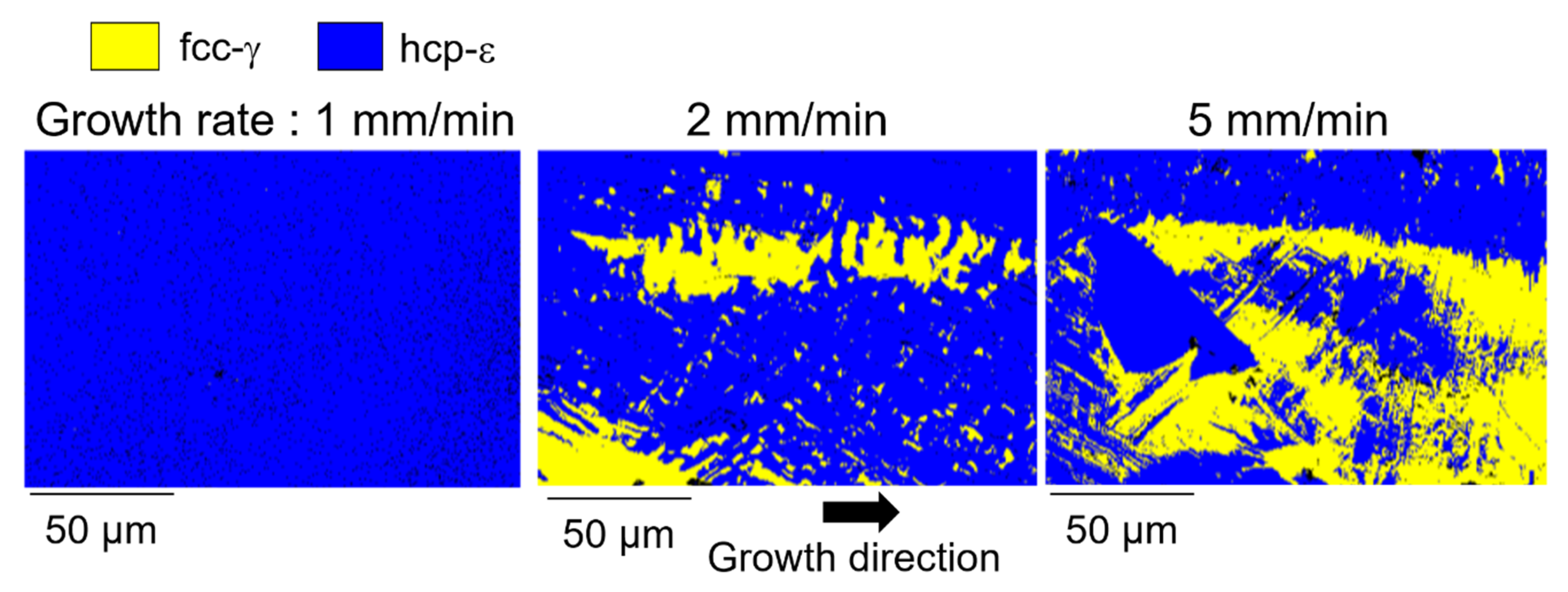
 [Green Version]
Figure 1. (a) Liquid–solid interface during fabrication of Co-Cr-Mo fiber. Co-Cr-Mo fibers fabricated under (b) Ar and (c) Ar + 3%H2 atmosphere.
Crystals 10 00011 g001
Figure 2. Back-scattering electron (BSE) images and element mappings on polished surfaces parallel to the growth direction for the Co-Cr-Mo fibers fabricated under (a) Ar and (b) Ar + 3%H2 atmosphere.
Crystals 10 00011 g002
Figure 3. Scanning electron (SE) images on the cross-section polisher (CP) treated surfaces parallel to the growth direction for the Co-Cr-Mo fibers fabricated at (a) 2 mm/min and (b) 5 mm/min growth rates.
Crystals 10 00011 g003
Figure 4. Chemical composition analyses on the treated surfaces of the Co-Cr-Mo fibers fabricated at 2 and 5 mm/min growth rates by an energy-dispersive X-ray spectrometer (EDX). (a) Element mappings of Mo along the growth direction. (b) Element distributions of Co, Cr, and Mo along the black arrow in the element mappings of Mo.
Crystals 10 00011 g004
Figure 5. Phase maps along the growth direction on the treated surfaces of the Co-Cr-Mo fibers fabricated at 1, 2, and 5 mm/min growth rates, measured by electron backscattering diffraction (EBSD). Yellow and blue areas are fcc-γ and hcp-ε phases, respectively.
Crystals 10 00011 g005
Table 1. The ratio of each phase and zero solution in the Co-Cr-Mo fibers.
Phase1 mm/min2 mm/min5 mm/min
fcc-γ0.01%23.49%36.51%
hcp-ε96.01%75.42%61.76%
Zero solution3.98%1.09%1.73%

