Article

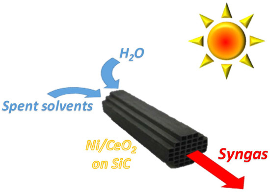
Ni/CeO2 Structured Catalysts for Solar Reforming of Spent Solvents

by
Gianluca Landi
1,* and
Almerinda Di Benedetto
2
1
Institute of Researches on Combustion-CNR, P.le Tecchio 80, 80125 Naples, Italy
2
Dipartimento di Ingegneria Chimica, dei Materiali e della Produzione Industriale, Univ. of Naples Federico II, P.le Tecchio 80, 80125 Naples, Italy
*
Author to whom correspondence should be addressed.
Catalysts 2019, 9(8), 688; https://doi.org/10.3390/catal9080688
Submission received: 19 July 2019 / Revised: 11 August 2019 / Accepted: 12 August 2019 / Published: 15 August 2019
(This article belongs to the Special Issue Catalytic Applications of CeO2-Based Materials)

Abstract

:
Spent solvents of the packaging industry are disposed of, thus representing economic, safety, and environmental issues. Steam reforming of these solvent streams can be an alternative, allowing their valorization to syngas. In this work, ceria supported nickel catalysts were deposed onto silicon carbide (SiC) honeycomb monoliths; these structured catalysts can be potentially used in solar steam reforming. Catalysts were characterized by SEM/EDS and tested in a lab-scale rig under conventional heating. Two spent solvent streams, coming from the distillation plant of the packaging industry Icimendue, were used as fuels. Catalytic tests have been carried out by changing the steam/carbon ratio, oxygen/carbon ratio, operating pressure, and fuel. The effect of the Ni content and the type of ceria were also studied. The best performances were obtained at low Ni content and by using micrometric rather than nanometric ceria as support. The structured catalysts showed good coking resistance, especially at H2O/C > 2, with oxygen addition furnishing a marginal improvement. On the contrary, oxygen feeding reduced the gas yield due to the formation of by-products being less reactive in reforming reactions. Performing the reforming process at high pressure the gas yield increased due to faster kinetics (higher reactants concentrations), higher contact times (slower flow rates), and process intensification. These results suggest that the proposed structured catalysts could be successfully applied in the solar reforming of spent solvents.

Graphical Abstract

1. Introduction

The packaging industry market is forecasted to steadily increase in the coming years [1]. Accordingly, the use of esters and alcohols as solvents will significantly increase. These solvents contribute to the increase of volatile organic compound (VOC) emissions, representing a crucial air pollution issue, faced by different technologies [2,3]. In the packaging industry, solvent recovery is generally carried out, consisting of an activated carbon plant, which adsorbs the post-printing exhaust solvents, and a distillation system, which separates the recovered solvent mixture [3]. The solvent recovery stage is characterized by by-products, i.e., waste streams to be disposed of, thus implying additional costs as well as safety issues [4]. In this framework, catalytic combustion of these waste streams is proposed as an alternative solution which allows heat recovery [4].
Due to the considerable chemical potential of the waste streams deriving from the distillation stage, a valid alternative to disposal is represented by their valorization. Waste streams are mainly constituted by alcohols and esters [4]. These compounds (mainly ethanol) have been widely used as fuels in reforming processes [5,6,7,8,9,10,11,12]. As a consequence, an alternative path to catalytic combustion may be the upgrading of the spent solvents to syngas by steam reforming, which could eventually allow the production of a clean, renewable, and flexible energy and chemical source, such as synthesis gas.
Reforming reactions are endothermic and, thus, large heat fluxes are required in order to convert fuel into syngas. At an industrial scale, heat supply is provided by fuel combustion. Interestingly, solar steam reforming has been proposed [13,14]; concentrated solar power (CSP) can be produced by sunlight concentration, transferred to solar receivers, and converted into thermal energy [15]. This thermal power could be used to sustain endothermic reactions such as steam reforming. Monolithic and porous media have received attention as possible solar receivers [16,17,18,19]. In particular, Fend et al. [17] suggested that a good volumetric solar receiver should show high porosity, high cell density, temperature resistance, thermal conductivity, 3D structure, and dark color. Silicon carbide (SiC) monoliths show the above features [17,20,21] and good interaction with electromagnetic waves [22], thus representing a good choice as substrates for solar structured catalytic reactors [23].
In the steam reforming of oxygenated compounds, both transition metals, such as Co, Ni, Fe, and Cu [6,7,24,25,26,27,28,29,30,31,32,33], and noble metals, such as Pt, Pd, Rh, and Ru [9,11,24,28,34,35,36,37,38,39], were tested, Ni-based catalysts representing the best compromise between activity and cost. Ceria as support generally improves catalytic activity, thermal stability, and coking resistance [7,9,31,32,33].
According to the above considerations, in this work, structured catalysts potentially usable in solar steam reforming have been prepared by washcoating SiC honeycomb monoliths with Ni/CeO2 catalysts with different Ni loadings. To the best of our knowledge, reforming of spent solvents has been reported only by Yang et al. [10] on an Rh/CeO2 catalyst, by feeding butylene as the product of the thermal decomposition of spent tributyl phosphate. In this work, real spent solvents, namely the azeotropic stream (AZ) and the high-boiling-point stream (HB), whose compositions are reported in Section 4, coming from the distillation plant of the packaging industry Icimendue (www.icimen.com), were used as fuels. Catalytic tests have been carried out by changing the steam/carbon ratio, oxygen/carbon ratio, and operating pressure. In particular, while steam reforming at an industrial scale is performed at high pressure (generally 20–40 atm), studies on the reforming of oxygenated compounds are generally performed at atmospheric pressure, because they are aimed at H2 production for fuel cells.

2. Results

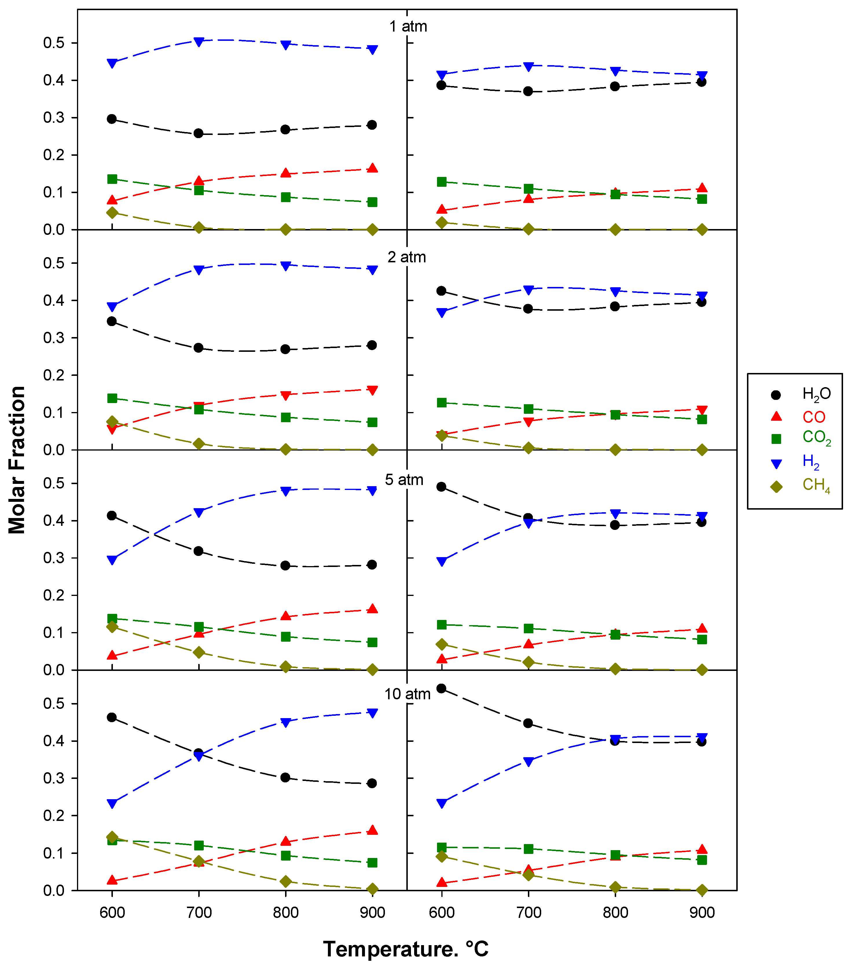
2.1. Thermodynamic Analysis

Figure 1 shows the predicted compositions as a function of temperature at different pressures and H2O/C ratios for the AZ solvents mixture. C formation (included in the simulations) is not found and solvents are completely converted under any reaction conditions. At low temperature, the main reactions occurring are the solvents decompositions. By increasing the temperature, CO and H2 fractions increase at the expense of CH4 and CO2. This is due to the shifts of methane steam reforming and water gas shift reactions towards their products. As expected, by increasing pressure, higher temperatures are needed to avoid CH4 formation, while higher H2O/C ratios enhance CH4 conversion into syngas.
Similar results were obtained with HB solvents mixture as the reactant. The above results show that at high-temperature, complete solvent conversion to syngas could be obtained independently from the operating pressure, especially at H2O/C ratio higher than two. Oxygen addition (not reported) enlarges the operating window showing low CH4 yield; however, yields to CO and H2 decrease as well.

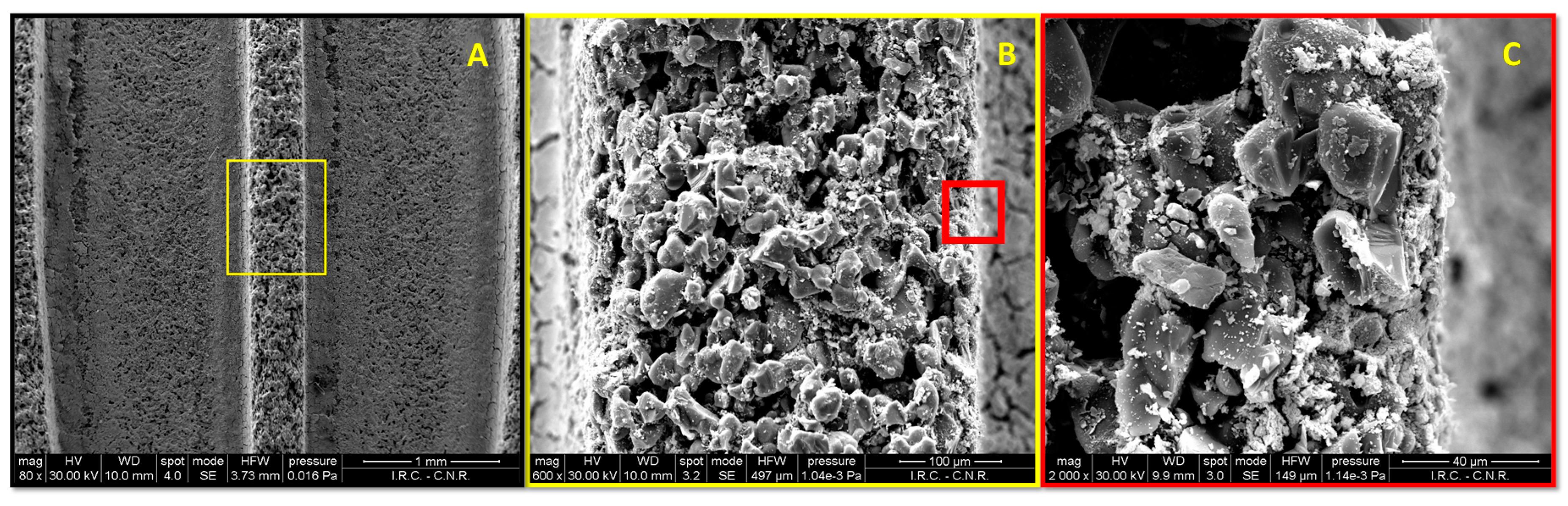
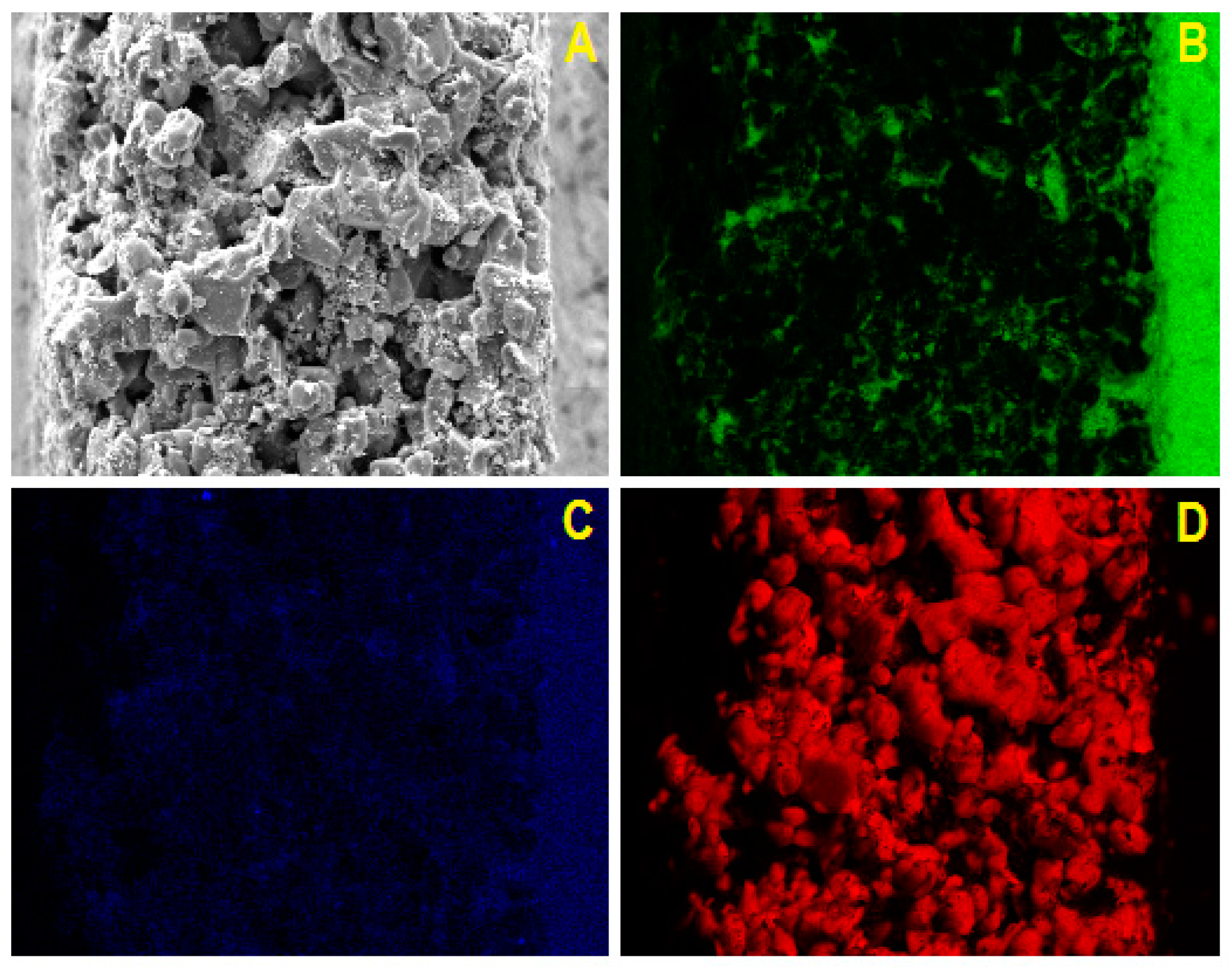
2.2. SEM/EDX Characterization

The surface morphology of the monolithic catalyst and the Ni and Ce distribution were investigated by means of SEM analysis, in combination with EDX. The porous structure of silicon carbide is shown in Figure 2. Pore characteristic dimension is about 10 μm, i.e., significantly larger than particles used for slurry preparation, thus suggesting that the washcoat can easily penetrate into the walls of the honeycomb monolith. As a matter of fact, Figure 2C shows the penetration of the washcoat inside the channel wall. The thickness of the washcoat layer on the outer part of the monolith walls is about 8–10 μm, in agreement with the penetration of a part of the washcoat. Ceria distribution on the substrate appears uniform and homogeneous on the walls with accumulation at the corners, as previously reported for similar monoliths [40]. Figure 3 shows the EDX analysis of the monolith walls. On the right of each image, the washcoat layer deposited onto the walls can be identified (no Si is detected). The presence of Ni and Ce together with Si, i.e., inside the wall, confirms the penetration of the washcoat inside the silicon carbide walls. Good contact between support and active phase can be noted by comparing Ce and Ni distributions.

2.3. Catalytic Tests

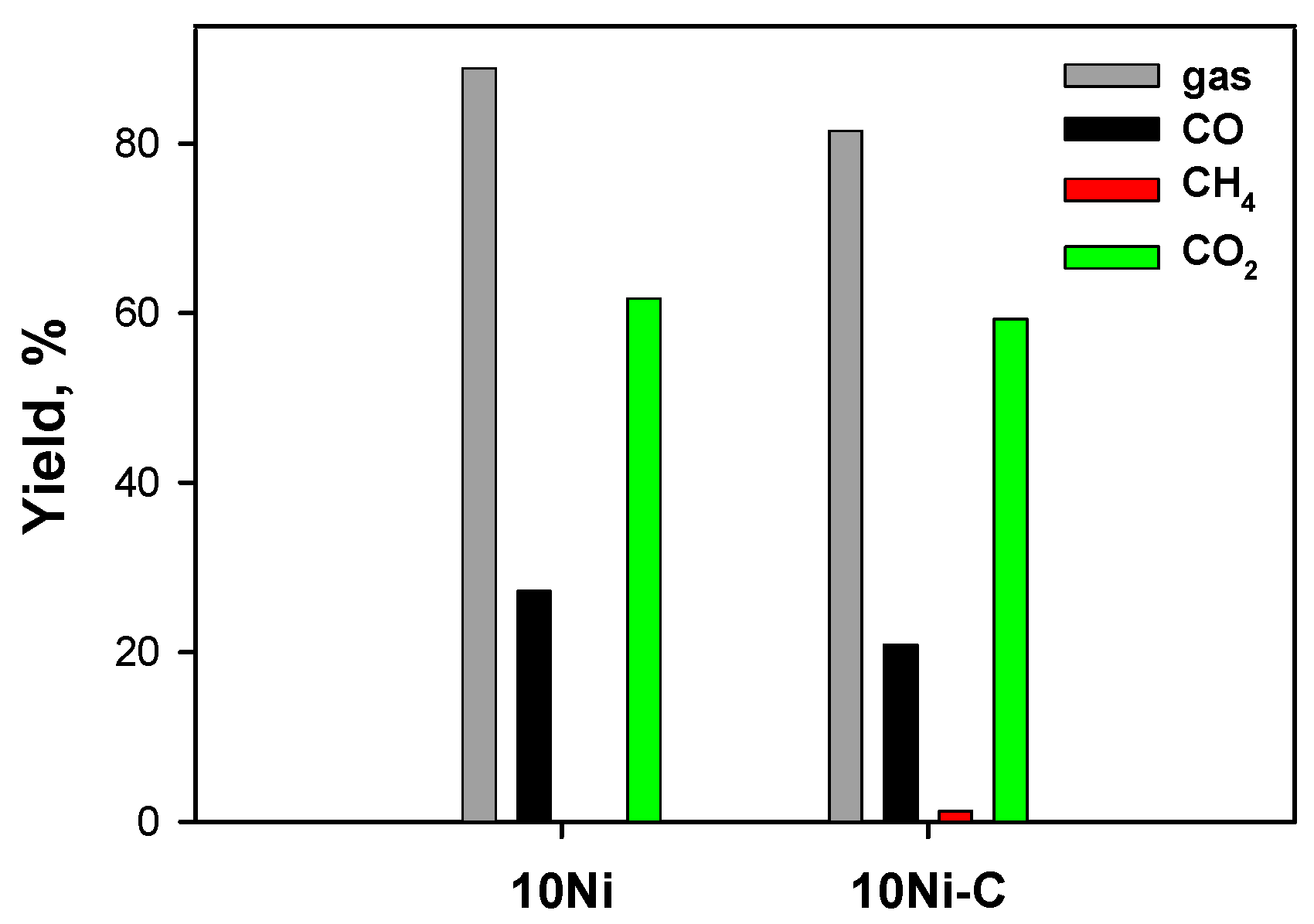
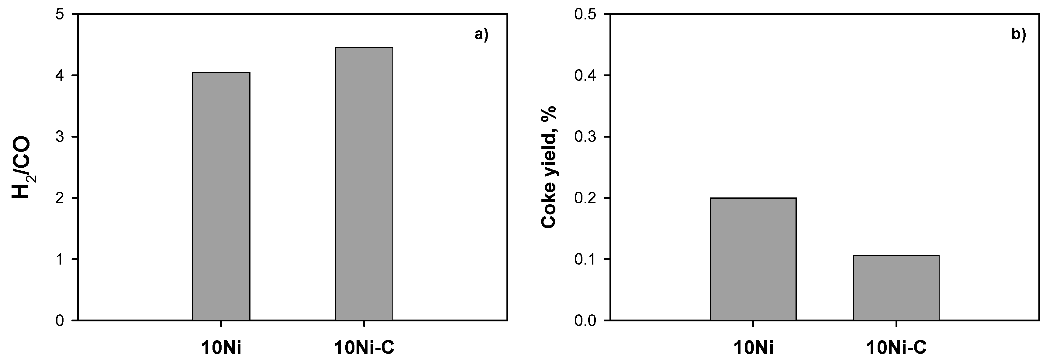
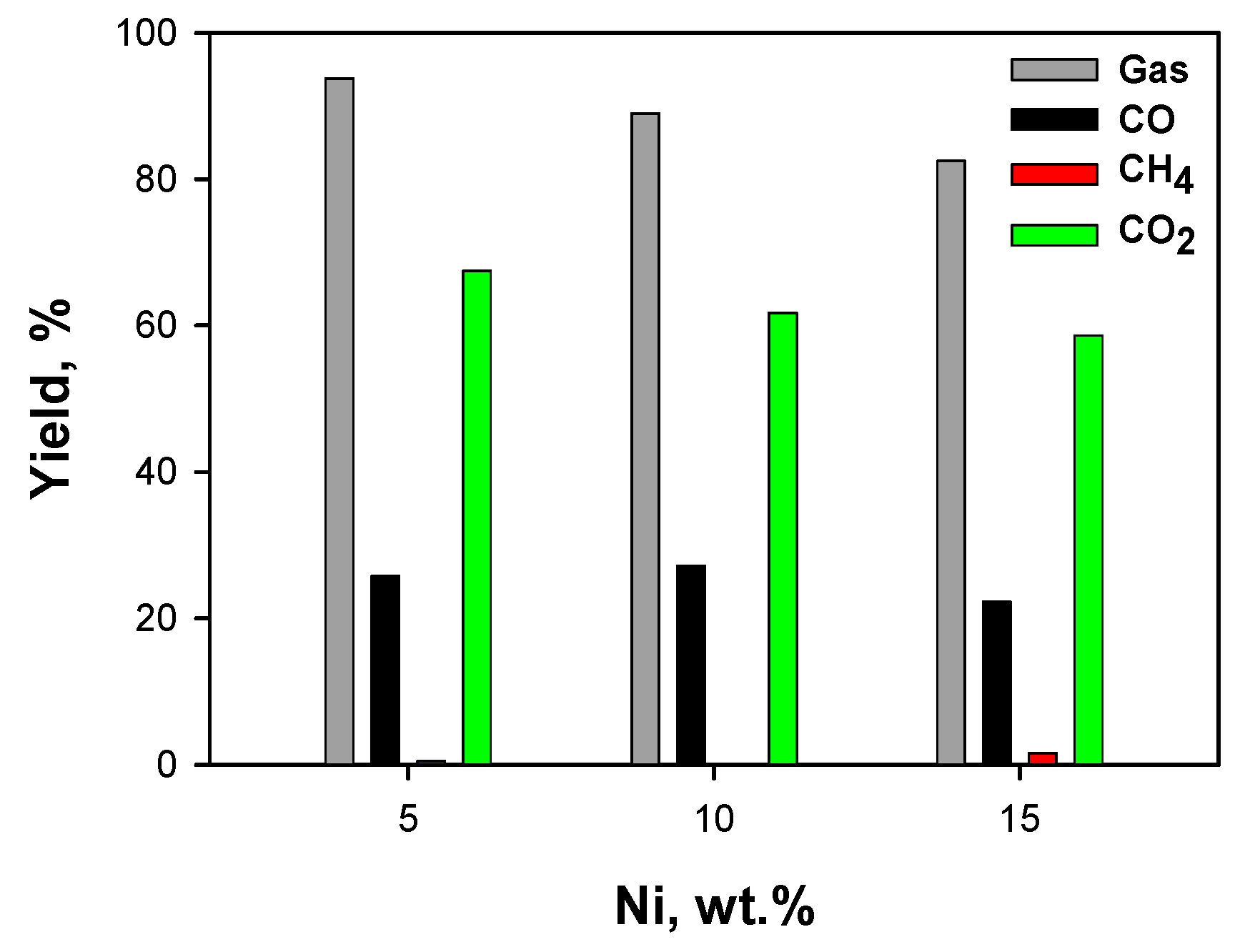
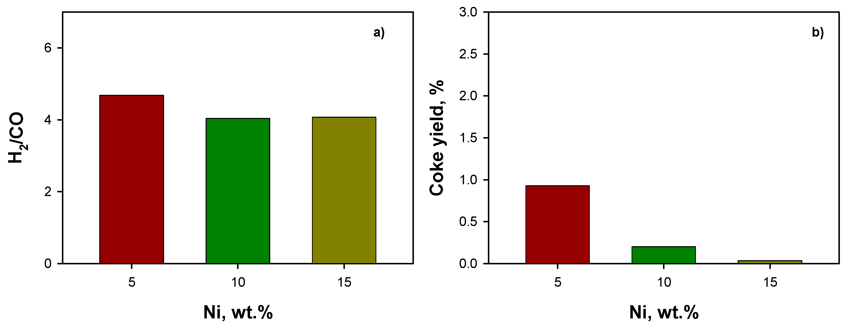
2.3.1. Effect of Ceria Source and Ni Loading: HB Mixture

Catalytic tests were carried out at 720 °C, at atmospheric pressure, and an H2O/C ratio equal to 3 on the 10 Ni and 10 Ni-C samples in order to evaluate the effect of the starting dimension of the ceria particles used to washcoat the monoliths. Oxygen was added to the gas mixture (O2/C = 0.4) to avoid coke deposition. Figure 4 shows the gas yield ηgas and the yields to CO, CO2, and CH4 for the two structured catalysts. High but incomplete gasification and high CO2 yields are obtained on both catalysts. Best performance is measured on 10 Ni, showing a lower CH4 yield too. The H2/CO ratio (Figure 5a) slightly increases on the 10 Ni-C due to its lower CO yield. Figure 5b shows the yield to coke formed during the test sets on 10 Ni and 10 Ni-C catalysts. Coke formation is quite negligible in both samples, as expected in the presence of molecular oxygen in the feed stream. As reported in Landi et al. [41], nanometric ceria from colloidal suspension more deeply penetrates into monolith walls with respect to micrometric ceria. Accordingly, the lower performance of the 10 Ni-C structured catalyst can be due to a deeper active layer penetration into the walls, leading to a reduced contact between gaseous reactants and catalytic sites, and therefore a lower gas yield.
Consequently, the effect of Ni content was studied on catalysts prepared by using commercial ceria powder as ceria source.
Figure 6 shows the gas yield ηgas and the yields to CO, CO2, and CH4 as a function of the Ni load, while Figure 7 shows the corresponding H2/CO ratio (Figure 7a) and the yields to coke (Figure 7b). The increase of the active phase load does not provide significant changes in the composition of the products, the yields to gaseous products and the H2/CO being quite similar. The slight variations suggest that the yields decrease as the nickel increases, especially in terms of gas yield. This behavior could be addressed to the lower nickel dispersion on the substrate at high loadings [42]. The yield to coke decreases by increasing the Ni loading, suggesting that reactions leading to coke precursors are disadvantaged at high Ni content. However, yield to coke is always lower than 1%, suggesting a high coking resistance of Ni/CeO2 samples independently from the Ni content. The above results suggest that high performance and resistance against coking can be achieved at the lowest Ni content, also ensuring the lowest cost of the catalyst.

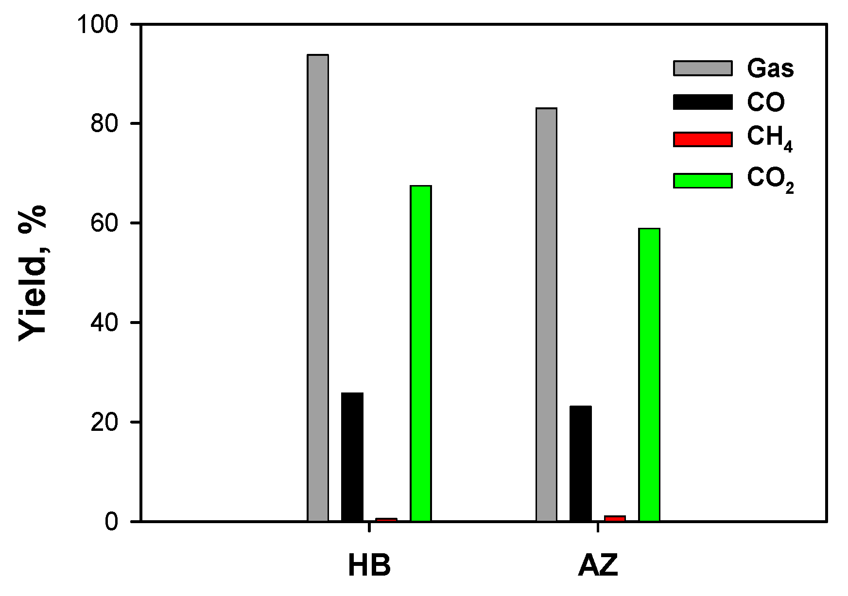
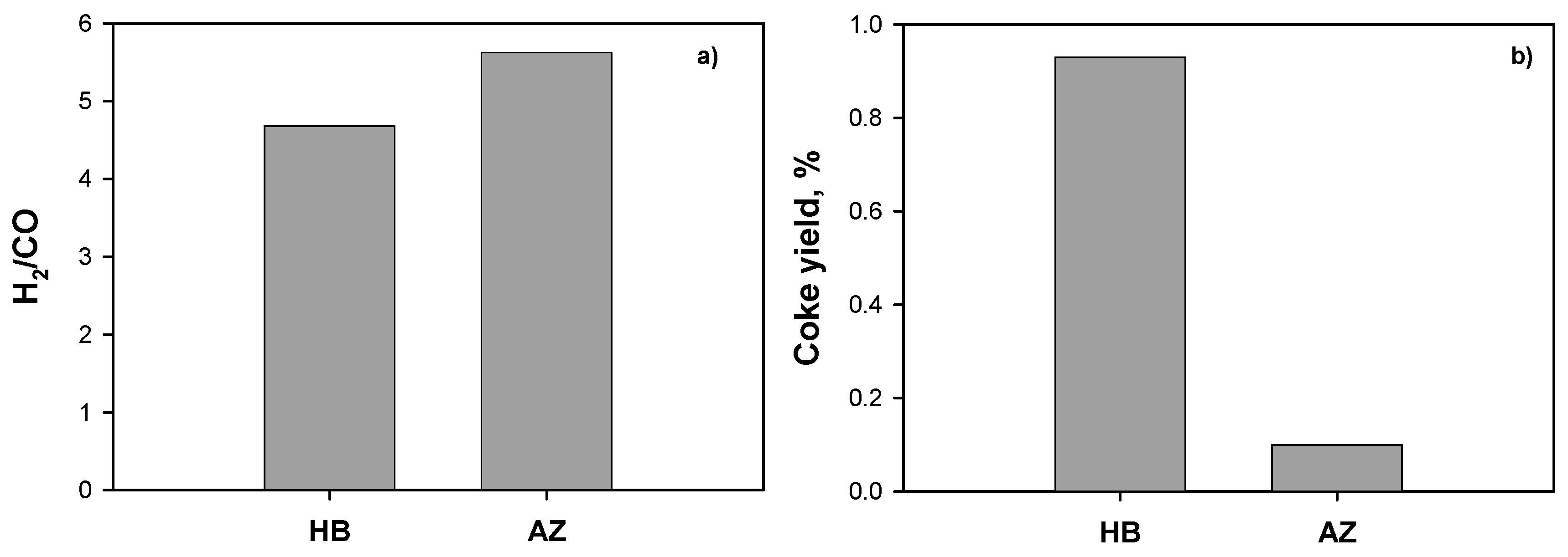
2.3.2. Effect of Solvents Mixture

Catalytic tests were carried out at 720 °C, at atmospheric pressure and H2O/C ratio equal to 3 on the 5 Ni catalyst by feeding HB or AZ solvents mixture. Figure 8 shows the gas yield ηgas and the yields to CO, CO2, and CH4 as a function of the fed solvents mixture, while Figure 9 shows the corresponding H2/CO ratios (Figure 9a) and the yields to coke (Figure 9b). The HB mixture clearly appears more reactive than the AZ mixture, providing a higher gas yield and lower yield to CH4. The AZ mixture is characterized by a higher H2/CO ratio, due to its intrinsically higher hydrogen content. As expected, the HB mixture shows a higher yield to coke. Further tests will be conducted on AZ mixtures, as it is the less reactive one.

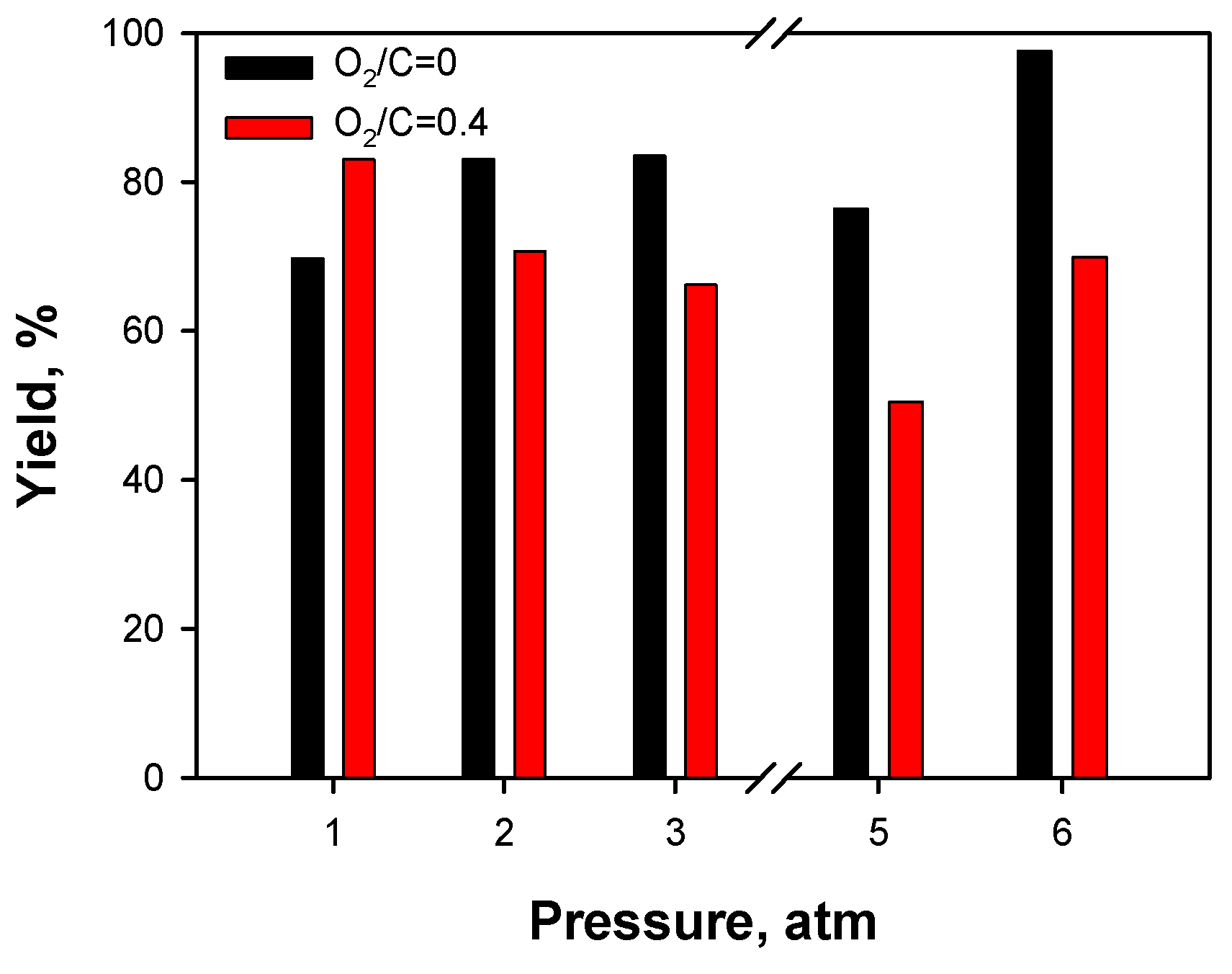
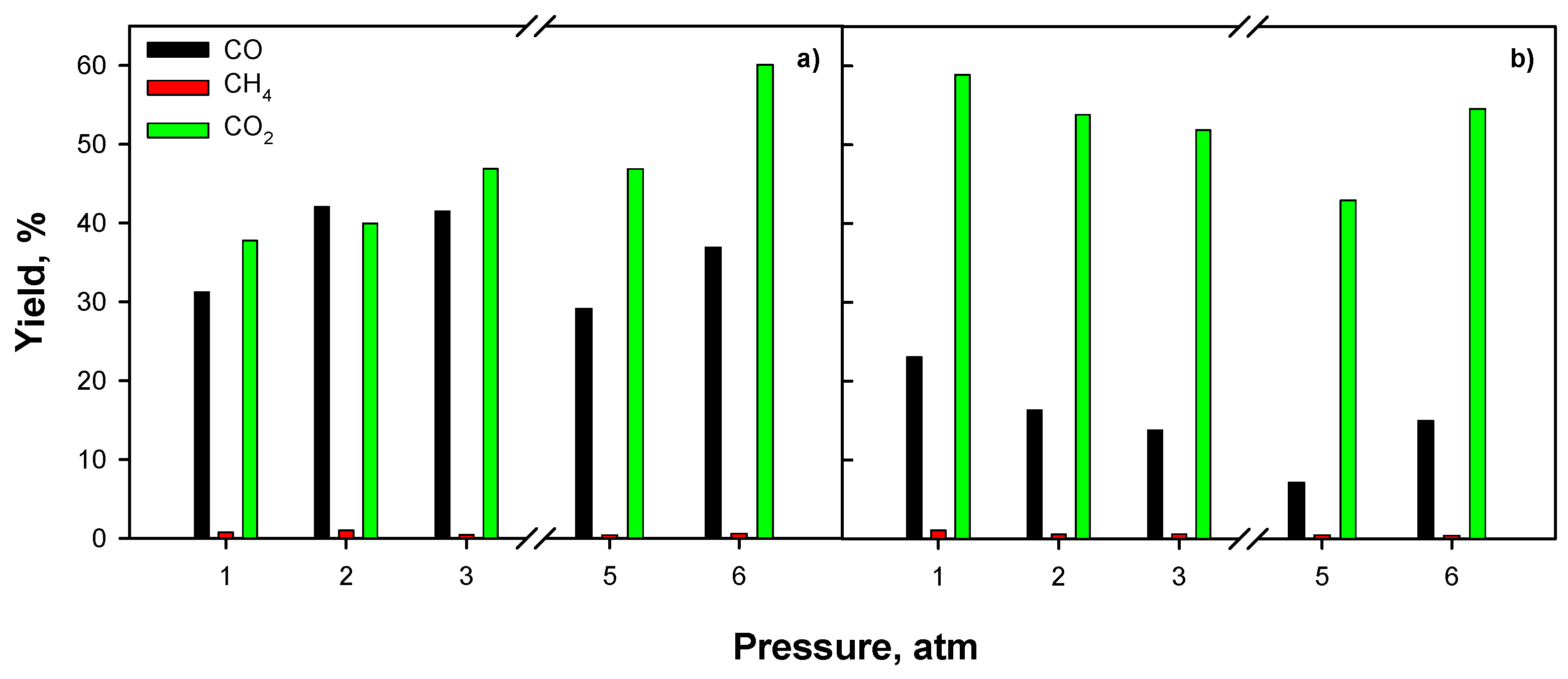
2.3.3. Effect of Operating Conditions: AZ Mixture

Catalytic tests were carried out at 720 °C on the 5 Ni monolith by feeding the AZ mixture. The effect of oxygen has been evaluated by using an oxygen-free gaseous feed. Moreover, the operating pressure was also changed between 1 and 6 atm. Figure 10, Figure 11 show the gas yield ηgas and the yields to CO, CO2, and CH4 as a function of the operating pressure respectively for two O2/C ratios, while Figure 12 shows the corresponding H2/CO ratios (Figure 12a) and the yields to coke (Figure 12b). By increasing the pressure, the gas yield increases at O2/C = 0, while it mainly decreases in the presence of oxygen in the feed stream. Moreover, the gas yield is higher in the absence of oxygen, except when at atmospheric pressure. As expected, O2 feeding reduces the CO yield by increasing CO2 formation, as it promotes combustion reactions with respect to the reforming ones. Yields to CH4 are low, independently from the reaction conditions, especially at high pressure. Higher H2/CO are measured when oxygen is fed mainly due to the lower CO production (Figure 12a). As expected, yield to coke (Figure 12b) decreases by adding O2 in the feed stream; however, coke formation is very low (yield ≤ 0.5%) in both cases, suggesting high coking resistance of the 5 Ni structured catalyst.
It is worth noting that at low pressure, the trend with pressure agrees with the thermodynamic trend (Figure 1), while at high pressure the syngas yields exhibit an opposite trend with pressure.
Figure 13 shows the gas yield ηgas as a function of the operating pressure at an H2O/C ratio equal to 2 and 3. Both pressure and H2O/C ratio positively affect gas yield. In particular, a larger water vapor concentration not only enhances reforming kinetics, but also disadvantages the dehydration equilibria, thus reducing the formation of undesired by-products, and promotes the decomposition reaction of acetaldehyde to CH4, CO2, and H2 with respect to recombination into acetone, representing a coke precursor.
Figure 14 shows yields to CO, CO2, and CH4. Both CO and CO2 production increase as the H2O/C ratio increases, as the steam-reforming reactions are favored over decomposition reactions, with a consequent CH4 reduction. The CO2 yield is even more enhanced due to the promotion of Water Gas Shift (WGS) reaction at larger H2O/C ratio.
The effect of pressure (Figure 13, Figure 14) is to slightly accelerate gas production, mainly as CO and CO2. This trend is due to faster catalytic kinetics related to the higher reactants concentrations and to a slower gas flow rate, with a consequent increase of the contact time.
H2/CO ratio (Figure 15a) increases with increasing both H2O/C feeding ratio and pressure, in agreement with the thermodynamic trend, due to the promotion of the reforming and WGS reactions. Moreover, as the gas yield increases, H2 production is enhanced at high pressure and when H2O/C = 3.
Figure 15b shows the yield to coke formed during the test sets at different H2O/C ratios. Coke formation is significant at H2O/C = 2, while it is considerably reduced as the H2O/C ratio increases, probably due to the promotion of gasification reactions at larger H2O concentrations.

3. Discussion

The results reported in the previous section suggest several considerations.
The main goal of this work, i.e., preparing a structured catalyst suitable for solar reforming of spent solvents, was successfully achieved. The best catalyst was 5 Ni, showing the lowest Ni content; this result was quite unexpected. As a matter of fact, catalytic activity usually shows a maximum by increasing the active phase loading [24,43], the most common compositions being 10–20 wt % [43]. The best performance of 5 Ni can be due to good Ni dispersion and strong interaction with the support, also promoting coking resistance [35,43]. Moreover, a deeper penetration of washcoat into the SiC walls by washcoating with colloidal nanometric ceria appeared detrimental for the catalytic performance. This behavior is expected with fast reactions showing mass transfer limitations [40,41]; this result suggests that reforming reactions occurring on our structured catalysts are not under a kinetic regime. Accordingly, the presence of methane among the gaseous products on 10 Ni/C could be due to the lower performance of this catalyst, as methane produced by side reactions could not be converted to syngas by reforming reactions due to a more difficult contact with the active phase located in less accessible positions of the monolith. A deeper analysis of this behavior is necessary and it will be reported in future work. Anyway, the catalytic results show that performing catalysts can be prepared with commercial ceria at low Ni loadings.
The interpretation of the effect of the operating conditions is not trivial. Previous studies were carried out on ethanol [5,6,7,9,12,26,27,29,33,35,44,45,46], ethyl acetate [12,43,47,48,49,50,51], and acetic acid [12,24,27,34,35,36,44], but not on mixtures of all three. In the following, a simplified scheme of the possible reactions involving the main components of the AZ mixture is reported (Equations (1)–(30)) [43].
Ethanol steam reformingC2H5OH + H2O → 2CO + 4H2(1)
Water gas shiftCO +H2O ↔ CO2 + H2(2)
Ethanol dehydrogenationC2H5OH → C2H4O + H2(3)
Ethanol dehydration to ethyleneC2H5OH → C2H4 + H2O(4)
Ethylene decompositionC2H4→ 2C + 2H2(5)
Acetaldehyde decompositionC2H4O → CH4 + CO(6)
Acetaldehyde steam reformingCH3CHO + H2O → 2CO + 3H2(7)
Ethanol water oxidationC2H5OH + H2O → CH3COOH + 2H2(8)
Ethanol decompositionC2H5OH → CH4 + CO + H2(9)
Acetadehyde recombination2CH3CHO→ CH3COCH3 + CO + H2(10)
Acetone steam reformingCH3COCH3 + 3H2O → 3CO + 6H2(11)
Methane steam reformingCH4 + H2O ↔ CO + 3H2(12)
Methane dry reformingCH4 + CO2 ↔ 2CO + 2H2(13)
CO methanationCO + 3H2 ↔ CH4 + H2O(14)
Acetic acid steam reformingCH3COOH + H2O → 2CO + 3H2(15)
Ketonization2CH3COOH → CH3COCH3 + CO2 + H2O(16)
Acetic acid decomposition (1)CH3COOH → CH4 + CO2(17)
Acetic acid decomposition (2)CH3COOH → 2H2 + CO2 + C(18)
DehydrationCH3COOH → CH2CO + H2O(19)
Ketene steam reformingCH2CO + H2O → 2CO + 2H2(20)
Ketene coupling2CH2CO → C2H4 + 2CO(21)
Acetone aldol condensation2CH3COCH3 → H2O + (CH3)2CCHCOCH3(22)
Condensation(CH3)2CCHCOCH3 + CH3COCH3 → C9H12 + 2H2O(23)
Coke formationC9H12 → Coke(24)
Ethyl acetate reformingC4H8O2 + 2H2O → 4 CO + 6 H2(25)
Ethyl acetate hydrogenationC4H8O2 + H2 → CH3CHO + CH3CH2OH(26)
Ethyl acetate decompositionC4H8O2 → 2 CH4 + 2 CO(27)
Boudouard reaction2CO ↔ CO2 + C(28)
Reverse gasificationCO + H2 ↔ H2O + C(29)
Methane decompositionCH4 ↔ C+ 2H2(30)
In the presence of oxygen in the feed stream, total and partial oxidation reactions have to be added.
Equations (1)–(30) provide an idea of the complexity of the reaction network involved in the steam reforming of spent solvents.
The relative trends of yields to CO, CO2, and CH4 can be explained by considering the behavior of reforming and methanation reactions in terms of both kinetic and thermodynamics as a function of pressure, H2O/C, and O2/C.
On the contrary, the trend of the gas yield is not trivial. In the absence of oxygen, the most favorable reactions are the ethanol (the main component of the AZ mixture) decomposition reactions to CO, CH4, and H2, and the steam and dry reforming processes [52]. On the contrary, in the presence of oxygen, partial and/or complete oxidation reactions of the oxygenated species prevail, followed by steam reforming, as generally occurring in autothermal reforming and partial oxidation processes. However, partial oxidation of oxygenated compounds leads to the formation of acetaldehyde, decomposing into acetone, that can be converted into acetic acid [39]. These products are less prone to be reformed and thus are undesirable condensable by-products lowering the gas yield [43]. The positive effect of the H2O/C ratio is due to the shift of reforming reactions and acetaldehyde decomposition and the inhibition of dehydration reactions [39,53].
Accordingly, the larger coke formation at H2O/C = 2 can be due to the improved formation of ketene and acetone, leading to coke formation especially at low steam partial pressure [39,53].
Results reported in the previous section demonstrated the positive effect of pressure on the reforming kinetics in the absence of oxygen in the feed stream. Despite the fact that the theoretical syngas yield should decrease by increasing the pressure (as thermodynamic calculations showed), lower amounts of condensable products are obtained at pressures higher than the atmospheric one; this is related to the combined effects of faster catalytic kinetics (higher reactants concentrations) and increased contact times (slower gas flow rate). In addition, higher pressures also guarantee process intensification.
Steam reforming of solvents has shown promising results which may be further improved by exploring the effect of all the operating conditions and catalyst compositions. On the other hand, a deeper understanding of the process can take place through a more in-depth study of kinetics and reaction mechanisms, especially considering that the solvent mixtures used in this work are not model mixtures, but come from a real distillation plant and therefore, they contain a series of components present in small quantities, which can, in turn, significantly affect the catalyst activity. Some of the components of the mixtures, especially those of the HB mixture, have not yet been studied as model compounds.
Finally, tests reported in this work were carried out under diluted conditions in order to assess the catalytic activity. So, no effect of the heat of the reaction on the thermal profile and, thus, on the catalytic performance has been detected. Tests under more concentrated conditions are thus necessary and will be reported in future work.

4. Materials and Methods

Structured catalysts were prepared, starting from commercial honeycomb monoliths, made by SiC (Ibiden (180 cpsi)), and cut in the desired shape and dimensions (cylinder; D = 13 mm; L = 50 mm) and commercial ceria (Treibacher). A ceria washcoat was deposited onto the monoliths by a modified dip-coating procedure. The main CeO2 amount was deposited according to the procedure reported in [40,41]. Briefly, monoliths were dipped in a slurry (CeO2 = 25 g; HNO3 (65%) = 2 g; H2O = 100 ml), dried at 120 °C for 1 h and calcined in air at 450 °C for 2 h. This procedure was repeated until the desired ceria weight (12 wt %, corresponding to about 15 µm layer) deposited on the monolith walls was obtained. Then, the monoliths were dipped into a commercial colloidal ceria (Nyacol Nano Technologies Inc., CeO2 particle size < 20 nm), dried at 120 °C for 1 h and calcined in air at 900 °C for 3 h. Nanometric ceria addition improves washcoat adhesion [41]. The active phase has been added by wet impregnation. Monoliths were dipped in an aqueous solution of nickel nitrate (Sigma-Aldrich), dried at 120 °C for 1 h and calcined at 450 °C for 2 h. The procedure was repeated until the desired nickel oxide load was obtained. In addition, a monolith was prepared by using only the colloidal suspension as ceria source. Table 1 reports labels, nominal Ni contents, and ceria source of the prepared structured catalysts, while Figure 16 shows a picture of the washcoated and final monolith.
The actual metal content was determined by ICP-MS analysis using an Agilent 7500CE instrument; differences with the nominal content were within the experimental error. The internal morphology of channels was observed using an FEI Inspect Scanning Electron Microscope (SEM) equipped with an energy dispersive X-ray (EDX) probe for the elemental mapping. A monolith was cut in order to analyze inner channels.
Catalytic tests were carried out in an ad-hoc lab-scale test rig, described elsewhere [54] and modified to adapt to the actual experimental conditions. In particular, a liquid feeding system was added to the existing rig. A liquid H2O/solvents mixture was previously prepared and fed to the reactor by means of a volumetric pump (KNF lab, SIMDOS 02); before entering into the reactor, the liquid flow was vaporized by means of a heating tape. The gaseous flow rate was set at 90 l (STP)/h, corresponding to a GHSV0 equal to 13500 h−1 at atmospheric pressure and temperature. The actual GHSV can be calculated as
G H S V = G H S V 0 · P · T 0 P 0 · T ,
where P and T are the actual pressure and temperature, while P0 and T0 are the atmospheric pressure and temperature; pressures are measured in atm and temperatures in K. Downstream the reactor, the gaseous mixture was cooled in order to separate condensable species. At a fixed temperature, the reactor pressure was changed between 1 and 6 atm; at each pressure, steady-state reaction conditions were obtained and gas composition was monitored for 30 min. In this work, two different solvent mixtures (azeotropic and high-boiling point, labeled as AZ and HB respectively) were employed, whose compositions are reported in Table 2. After each set of catalytic tests (i.e., tests at different pressures as described above), the reactor was cooled down to 70 °C in N2 and then a temperature-programmed oxidation (TPO; 10 °C/min up to 700 °C) was carried out in order to evaluate carbon deposition onto the catalyst surface by quantifying the emitted CO and CO2. The following parameters have been calculated:
η g a s = n C O + n C O 2 + n C H 4 n C _ i n l e t ,
η C O = n C O n C _ i n l e t ,
η C O 2 = n C O 2 n C _ i n l e t ,
η C H 4 = n C H 4 n C _ i n l e t ,
η C = n C O _ T P O + n C O 2 _ T P O n C _ i n l e t _ T O T ,
H 2 C O = n H 2 n C O ,
where ni are the molar amounts of the i species, nC_inlet is the molar carbon amount of the solvents mixture fed during the test, ηgas is the gas yield and ηi are the yields to the i species, nCO_TPO and nCO2_TPO are the molar amounts of CO and CO2 evolved during TPO respectively, nC_inlet_TOT is the molar carbon amount of the solvents mixture fed during the overall test set, and ηC is the yield to coke. Some tests were repeated and gave results that differ within the experimental error (± 4%), suggesting good thermal stability of the proposed structured catalysts.
A preliminary thermodynamic study has been carried out in order to identify proper reaction conditions. Equilibrium calculations were carried out with commercial simulation software Aspen Plus (AspenTech). Equilibrium was calculated by minimizing Gibbs free energy at specified operating conditions. In particular, the effect of temperature, pressure, and H2O/C ratio were investigated.

5. Conclusions

In this work, the catalytic steam reforming process of a waste stream coming from the solvent recovery stage of a packaging industry was proposed as an alternative to its disposal.
For this purpose, a low-cost nickel/ceria-based catalyst was used, supported on a silicon carbide monolith. This structured reactor has been designed to be used as a receiver in a solar reforming process. Two waste streams, reported as HB and AZ, coming from the distillation plant of the Icimendue company, were used to conduct laboratory-scale tests under conventional heating.
Thermodynamic calculations were performed to determine the best operating conditions for the production of syngas with high yields and low coke formation.
In regards to the composition of the catalyst, increasing the Ni concentration did not improve the catalytic performance, while the use of nanometric ceria as support negatively affected the gas yield, due to the deeper penetration of the active phase inside the walls of the SiC monolith.
Good coking resistance was shown by the proposed catalysts, especially at H2O/C > 2, with oxygen addition furnishing marginal improvement. Oxygen feeding reduced the gas yield due to the formation of by-products reacting less in reforming reactions.
Finally, a steam reforming process of spent solvents can benefit of operating pressure higher than the atmospheric one due to: i) Faster kinetics (higher reactants concentrations), ii) higher contact times (slower flow rates), and iii) process intensification.

Author Contributions

Conceptualization, G.L. and A.D.B.; data curation, G.L.; investigation, G.L. and A.D.B.; methodology, G.L. and A.D.B.; writing – original draft, G.L.; writing – review and editing, G.L. and A.D.B.

Funding

The present work has not been financially supported.

Acknowledgments

The authors gratefully acknowledge Luciano Cortese for SEM/EDX analysis

Conflicts of Interest

The authors declare no conflict of interest.

References

  1. Smithers Pira Packaging Industry Reports|Market Trends Analysis|Smithers Pira. Available online: https://www.smitherspira.com/industry-market-reports/packaging/the-future-of-global-packaging-to-2022 (accessed on 19 June 2019).
  2. Schlegelmilch, M.; Streese, J.; Stegmann, R. Odour management and treatment technologies: An overview. Waste Manag. 2005, 25, 928–939. [Google Scholar] [CrossRef] [PubMed]
  3. Henning, K.D. Solvent Recycling, Removal and Degradation. Handb. Solvents 2014, 2, 787–861. [Google Scholar]
  4. Landi, G.; Sarli, V.; Di Benedetto, A.; Di Berardini, F.; Mensitieri, M. Catalytic Combustion of Waste Streams Coming from the Solvent Recovery Stage of a Packaging Industry. J. Appl. Packag. Res. 2016, 8, 3. [Google Scholar]
  5. Compagnoni, M.; Tripodi, A.; Rossetti, I. Parametric study and kinetic testing for ethanol steam reforming. Appl. Catal. B Environ. 2017, 203, 899–909. [Google Scholar] [CrossRef]
  6. Konsolakis, M.; Ioakimidis, Z.; Kraia, T.; Marnellos, G. Hydrogen Production by Ethanol Steam Reforming (ESR) over CeO2 Supported Transition Metal (Fe, Co, Ni, Cu) Catalysts: Insight into the Structure-Activity Relationship. Catalysts 2016, 6, 39. [Google Scholar] [CrossRef]
  7. Moraes, T.S.; Rabelo Neto, R.C.; Ribeiro, M.C.; Mattos, L.V.; Kourtelesis, M.; Ladas, S.; Verykios, X.; Noronha, F.B. Ethanol conversion at low temperature over CeO2-Supported Ni-based catalysts. Effect of Pt addition to Ni catalyst. Appl. Catal. B Environ. 2016, 181, 754–768. [Google Scholar] [CrossRef]
  8. Goicoechea, S.; Ehrich, H.; Arias, P.L.; Kockmann, N. Thermodynamic analysis of acetic acid steam reforming for hydrogen production. J. Power Sources 2015, 279, 312–322. [Google Scholar] [CrossRef]
  9. Palma, V.; Castaldo, F.; Ciambelli, P.; Iaquaniello, G. CeO2-supported Pt/Ni catalyst for the renewable and clean H2 production via ethanol steam reforming. Appl. Catal. B Environ. 2014, 145, 73–84. [Google Scholar] [CrossRef]
  10. Yang, H.C.; Lee, M.W.; Hwang, H.S.; Moon, J.K.; Chung, D.Y. Study of cerium-promoted rhodium alumina catalyst as a steam reforming catalyst for treatment of spent solvents. J. Rare Earths 2014, 32, 831–836. [Google Scholar] [CrossRef]
  11. Le Valant, A.; Garron, A.; Bion, N.; Duprez, D.; Epron, F. Effect of higher alcohols on the performances of a 1%Rh/MgAl2O4/Al2O3 catalyst for hydrogen production by crude bioethanol steam reforming. Int. J. Hydrogen Energy 2011, 36, 311–318. [Google Scholar] [CrossRef]
  12. Hu, X.; Lu, G. Investigation of the steam reforming of a series of model compounds derived from bio-oil for hydrogen production. Appl. Catal. B Environ. 2009, 88, 376–385. [Google Scholar] [CrossRef]
  13. Liu, Q.; Wang, Y.; Lei, J.; Jin, H. Numerical investigation of the thermophysical characteristics of the mid-and-low temperature solar receiver/reactor for hydrogen production. Int. J. Heat Mass Transf. 2016, 97, 379–390. [Google Scholar] [CrossRef]
  14. Sheu, E.J.; Mokheimer, E.M.A.; Ghoniem, A.F. A review of solar methane reforming systems. Int. J. Hydrogen Energy 2015, 40, 12929–12955. [Google Scholar] [CrossRef] [Green Version]
  15. Yadav, D.; Banerjee, R. A review of solar thermochemical processes. Renew. Sustain. Energy Rev. 2016, 54, 497–532. [Google Scholar] [CrossRef]
  16. Agrafiotis, C.C.; Pagkoura, C.; Lorentzou, S.; Kostoglou, M.; Konstandopoulos, A.G. Hydrogen production in solar reactors. Catal. Today 2007, 127, 265–277. [Google Scholar] [CrossRef]
  17. Fend, T.; Pitz-Paal, R.; Reutter, O.; Bauer, J.; Hoffschmidt, B. Two novel high-porosity materials as volumetric receivers for concentrated solar radiation. Sol. Energy Mater. Sol. Cells 2004, 84, 291–304. [Google Scholar] [CrossRef]
  18. Wang, F.; Tan, J.; Shuai, Y.; Gong, L.; Tan, H. Numerical analysis of hydrogen production via methane steam reforming in porous media solar thermochemical reactor using concentrated solar irradiation as heat source. Energy Convers. Manag. 2014, 87, 956–964. [Google Scholar] [CrossRef]
  19. Bai, F. One dimensional thermal analysis of silicon carbide ceramic foam used for solar air receiver. Int. J. Therm. Sci. 2010, 49, 2400–2404. [Google Scholar] [CrossRef]
  20. Fend, T.; Hoffschmidt, B.; Pitz-Paal, R.; Reutter, O.; Rietbrock, P. Porous materials as open volumetric solar receivers: Experimental determination of thermophysical and heat transfer properties. Energy 2004, 29, 823–833. [Google Scholar] [CrossRef]
  21. Arellano-López, A.R.; Martínez-Fernández, J.; González, P.; Domínguez, C.; Fernández-Quero, V.; Singh, M. Biomorphic SiC: A New Engineering Ceramic Material. Int. J. Appl. Ceram. Technol. 2005, 1, 56–67. [Google Scholar] [CrossRef]
  22. Zhang, H.; Zhang, J.; Zhang, H. Computation of radar absorbing silicon carbide foams and their silica matrix composites. Comput. Mater. Sci. 2007, 38, 857–864. [Google Scholar] [CrossRef]
  23. Agrafiotis, C.C.; Mavroidis, I.; Konstandopoulos, A.G.; Hoffschmidt, B.; Stobbe, P.; Romero, M.; Fernandez-Quero, V. Evaluation of porous silicon carbide monolithic honeycombs as volumetric receivers/collectors of concentrated solar radiation. Sol. Energy Mater. Sol. Cells 2007, 91, 474–488. [Google Scholar] [CrossRef]
  24. Basagiannis, A.C.; Verykios, X.E. Catalytic steam reforming of acetic acid for hydrogen production. Int. J. Hydrogen Energy 2007, 32, 3343–3355. [Google Scholar] [CrossRef]
  25. Vagia, E.C.; Lemonidou, A.A. Hydrogen production via steam reforming of bio-oil components over calcium aluminate supported nickel and noble metal catalysts. Appl. Catal. A Gen. 2008, 351, 111–121. [Google Scholar] [CrossRef]
  26. Fatsikostas, A.N.; Verykios, X.E. Reaction network of steam reforming of ethanol over Ni-based catalysts. J. Catal. 2004, 225, 439–452. [Google Scholar] [CrossRef]
  27. Barattini, L.; Ramis, G.; Resini, C.; Busca, G.; Sisani, M.; Costantino, U. Reaction path of ethanol and acetic acid steam reforming over Ni-Zn-Al catalysts. Flow reactor studies. Chem. Eng. J. 2009, 153, 43–49. [Google Scholar] [CrossRef]
  28. Frusteri, F.; Freni, S.; Spadaro, L.; Chiodo, V.; Bonura, G.; Donato, S.; Cavallaro, S. H2 production for MC fuel cell by steam reforming of ethanol over MgO supported Pd, Rh, Ni and Co catalysts. Catal. Commun. 2004, 5, 611–615. [Google Scholar] [CrossRef]
  29. Comas, J.; Marino, F.; Laborde, M.; Amadeo, N. Bio-ethanol steam reforming on Ni/Al2O3 catalyst. Chem. Eng. J. 2004, 98, 61–68. [Google Scholar] [CrossRef]
  30. Frusteri, F.; Freni, S.; Chiodo, V.; Spadaro, L.; Di Blasi, O.; Bonura, G.; Cavallaro, S. Steam reforming of bio-ethanol on alkali-doped Ni/MgO catalysts: Hydrogen production for MC fuel cell. Appl. Catal. A Gen. 2004, 270, 1–7. [Google Scholar] [CrossRef]
  31. Moraes, T.S.; Neto, R.C.R.; Ribeiro, M.C.; Mattos, L.V.; Kourtelesis, M.; Verykios, X.; Noronha, F.B. Effects of ceria morphology on catalytic performance of Ni/CeO2 catalysts for low temperature steam reforming of ethanol. Top. Catal. 2015, 58, 281–294. [Google Scholar] [CrossRef]
  32. Italiano, C.; Bizkarra, K.; Barrio, V.L.; Cambra, J.F.; Pino, L.; Vita, A. Renewable hydrogen production via steam reforming of simulated bio-oil over Ni-based catalysts. Int. J. Hydrogen Energy 2019, 44, 14671–14682. [Google Scholar] [CrossRef]
  33. Iulianelli, A.; Liguori, S.; Vita, A.; Italiano, C.; Fabiano, C.; Huang, Y.; Basile, A. The oncoming energy vector: Hydrogen produced in Pd-composite membrane reactor via bioethanol reforming over Ni/CeO2 catalyst. Catal. Today 2016, 259, 368–375. [Google Scholar] [CrossRef]
  34. Basagiannis, A.C.; Verykios, X.E. Influence of the carrier on steam reforming of acetic acid over Ru-based catalysts. Appl. Catal. B Environ. 2008, 82, 77–88. [Google Scholar] [CrossRef]
  35. Matas Güell, B.; Babich, I.; Nichols, K.P.; Gardeniers, J.G.E.; Lefferts, L.; Seshan, K. Design of a stable steam reforming catalyst-A promising route to sustainable hydrogen from biomass oxygenates. Appl. Catal. B Environ. 2009, 90, 38–44. [Google Scholar] [CrossRef]
  36. Takanabe, K.; Aika, K.I.; Seshan, K.; Lefferts, L. Sustainable hydrogen from bio-oil—Steam reforming of acetic acid as a model oxygenate. J. Catal. 2004, 227, 101–108. [Google Scholar] [CrossRef]
  37. Liguras, D.K.; Kondarides, D.I.; Verykios, X.E. Production of hydrogen for fuel cells by steam reforming of ethanol over supported noble metal catalysts. Appl. Catal. B Environ. 2003, 43, 345–354. [Google Scholar] [CrossRef]
  38. Casanovas, A.; Llorca, J.; Homs, N.; Fierro, J.L.G.; Ramírez de la Piscina, P. Ethanol reforming processes over ZnO-supported palladium catalysts: Effect of alloy formation. J. Mol. Catal. A Chem. 2006, 250, 44–49. [Google Scholar] [CrossRef]
  39. Cavallaro, S.; Chiodo, V.; Freni, S.; Mondello, N.; Frusteri, F. Performance of Rh/Al2O3 catalyst in the steam reforming of ethanol: H2 production for MCFC. Appl. Catal. A Gen. 2003, 249, 119–128. [Google Scholar] [CrossRef]
  40. Barbato, P.S.; Di Benedetto, A.; Landi, G.; Lisi, L. CuO/CeO2 based monoliths for CO preferential oxidation in H2-rich streams. Chem. Eng. J. 2015, 279, 983–993. [Google Scholar] [CrossRef]
  41. Landi, G.; Barbato, P.S.; Di Benedetto, A.; Lisi, L. Optimization of the preparation method of CuO/CeO2 structured catalytic monolith for CO preferential oxidation in H2-rich streams. Appl. Catal. B Environ. 2016, 181, 727–737. [Google Scholar] [CrossRef]
  42. Bimbela, F.; Oliva, M.; Ruiz, J.; García, L.; Arauzo, J. Hydrogen production by catalytic steam reforming of acetic acid, a model compound of biomass pyrolysis liquids. J. Anal. Appl. Pyrolysis 2007, 79, 112–120. [Google Scholar] [CrossRef]
  43. Trane, R.; Dahl, S.; Skjøth-Rasmussen, M.S.; Jensen, A.D. Catalytic steam reforming of bio-oil. Int. J. Hydrogen Energy 2012, 37, 6447–6472. [Google Scholar] [CrossRef]
  44. Xie, H.; Yu, Q.; Yao, X.; Duan, W.; Zuo, Z.; Qin, Q. Hydrogen production via steam reforming of bio-oil model compounds over supported nickel catalysts. J. Energy Chem. 2015, 24, 299–308. [Google Scholar] [CrossRef]
  45. Fierro, V.; Klouz, V.; Akdim, O.; Mirodatos, C. Oxidative reforming of biomass derived ethanol for hydrogen production in fuel cell applications. Catal. Today 2002, 75, 141–144. [Google Scholar] [CrossRef]
  46. Fierro, V.; Akdim, O.; Provendier, H.; Mirodatos, C. Ethanol oxidative steam reforming over Ni-based catalysts. J. Power Sources 2005, 145, 659–666. [Google Scholar] [CrossRef]
  47. Xue, Z.; Shen, Y.; Li, P.; Zhang, Y.; Li, J.; Qin, B.; Zhang, J.; Zeng, Y.; Zhu, S. Key Role of Lanthanum Oxychloride: Promotional Effects of Lanthanum in NiLaOy/NaCl for Hydrogen Production from Ethyl Acetate and Water. Small 2018, 14, 1800927. [Google Scholar] [CrossRef] [PubMed]
  48. Ruhswurmova, N.; Kim, S.; Yoo, J.; Chun, D.; Rhim, Y.; Lim, J.; Kim, S.; Choi, H.; Lee, S. Nickel supported on low-rank coal for steam reforming of ethyl acetate. Int. J. Hydrogen Energy 2018, 43, 15880–15890. [Google Scholar] [CrossRef]
  49. Xue, Z.; Shen, Y.; Li, P.; Zhang, Y.; Zeng, Y.; Zhu, S. Controllable synthesis of carbon nanotubes via autothermal reforming of ethyl acetate. Mater. Des. 2018, 141, 150–158. [Google Scholar] [CrossRef]
  50. Baviskar, C.V.; Vaidya, P.D. Steam reforming of model bio-oil compounds 2-butanone, 1-methoxy-2-propanol, ethyl acetate and butyraldehyde over Ni/Al2O. Int. J. Hydrogen Energy 2017, 42, 21667–21676. [Google Scholar] [CrossRef]
  51. Xue, Z.; Shen, Y.; Zhu, S.; Li, P.; Zeng, Y.; Xi, Z.; Cai, Y. Autothermal reforming of ethyl acetate for hydrogen production over Ni3La7Oy/Al2O3 catalyst. Energy Convers. Manag. 2017, 146, 34–42. [Google Scholar] [CrossRef]
  52. Fishtik, I.; Alexander, A.; Datta, R.; Geana, D. Thermodynamic analysis of hydrogen production by steam reforming of ethanol via response reactions. Int. J. Hydrogen Energy 2000, 25, 31–45. [Google Scholar] [CrossRef]
  53. Mattos, L.V.; Jacobs, G.; Davis, B.H.; Noronha, F.B. Production of Hydrogen from Ethanol: Review of Reaction Mechanism and Catalyst Deactivation. Chem. Rev. 2012, 112, 4094–4123. [Google Scholar] [CrossRef] [PubMed]
  54. Barbato, P.S.; Di Benedetto, A.; Di Sarli, V.; Landi, G.; Pirone, R. High-pressure methane combustion over a perovskyte catalyst. Ind. Eng. Chem. Res. 2012, 51, 7547–7558. [Google Scholar] [CrossRef]
Figure 1. Equilibrium compositions as a function of temperature calculated at different pressures and H2O/C ratios. H2O/C = 2 on the left; H2O/C = 3 on the right. Fuel: Azeotropic stream (AZ).
Catalysts 09 00688 g001
Figure 2. SEM images of 10 Ni monolith. (A) 80× enlargement; (B) 600× enlargement of the yellow box reported in Figure A; (C): 2000× enlargement of the red box reported in figure B.
Catalysts 09 00688 g002
Figure 3. SEM image ((A) 2000× enlargement) and EDX analysis ((B) Ce; (C) Ni; (D) Si) of 10 Ni monolith.
Catalysts 09 00688 g003
Figure 4. Gas yield and yields to CO, CH4, and CO2 for 10 Ni and 10 Ni-C monoliths during steam reforming of the high-boiling-point stream (HB) mixture at 720 °C and atmospheric pressure; gas-phase feed composition: Solvent/H2O/O2/N2 = 0.7/6/0.8/92.5.
Catalysts 09 00688 g004
Figure 5. (a) H2/CO ratio for 10 Ni and 10 Ni-C monoliths during steam reforming of HB mixture at 720 °C and atmospheric pressure; gas-phase feed composition: Solvent/H2O/O2/N2 = 0.7/6/0.8/92.5. (b) Coke yields for 10 Ni and 10 Ni-C monoliths.
Catalysts 09 00688 g005
Figure 6. Gas yield and yields to CO, CH4, and CO2 as a function of the Ni content during steam reforming of HB mixture at 720 °C and atmospheric pressure; gas-phase feed composition: Solvent/H2O/O2/N2 = 0.7/6/0.8/92.5.
Catalysts 09 00688 g006
Figure 7. (a) H2/CO ratio for 5 Ni, 10 Ni, and 15 Ni monoliths during steam reforming of HB mixture at 720 °C and atmospheric pressure; gas-phase feed composition: Solvent/H2O/O2/N2 = 0.7/6/0.8/92.5. (b) Coke yields for 5 Ni, 10 Ni, and 15 Ni monoliths.
Catalysts 09 00688 g007
Figure 8. Gas yield and yields to CO, CH4, and CO2 as a function of the solvents mixture during steam reforming on 5 Ni at 720 °C and atmospheric pressure; gas-phase feed composition: Solvent/H2O/O2/N2 = 0.7/6/0.8/92.5.
Catalysts 09 00688 g008
Figure 9. (a) H2/CO ratio for the HB and AZ solvents mixtures during steam reforming on 5 Ni at 720 °C and atmospheric pressure; gas-phase feed composition: Solvent/H2O/O2/N2 = 0.7/6/0.8/92.5. (b) Coke yields for HB and AZ solvents mixture.
Catalysts 09 00688 g009
Figure 10. Gas yield as a function of pressure during steam reforming of AZ mixture on 5 Ni monolith at 720 °C; gas-phase feed composition: Solvent/H2O/O2/N2 = 0.7/6/0/93.3; 0.7/6/0.8/92.5.
Catalysts 09 00688 g010
Figure 11. Yields to CO, CH4, and CO2 as a function of pressure during steam reforming of AZ mixture on 5 Ni monolith at 720 °C; gas-phase feed composition: Solvent/H2O/O2/N2 = 0.7/6/0/93.3 (a); 0.7/6/0.8/92.5 (b).
Catalysts 09 00688 g011
Figure 12. (a) H2/CO ratio as a function of pressure during steam reforming of AZ mixture on 5 Ni monolith at 720 °C; gas-phase feed composition: Solvent/H2O/O2/N2 = 0.7/6/0/93.3; 0.7/6/0.8/92.5. (b) Coke yields as a function of the O2/C ratio.
Catalysts 09 00688 g012
Figure 13. Gas yield as a function of pressure during steam reforming of AZ mixture on 5 Ni monolith at 720 °C; gas-phase feed composition: Solvent/H2O/N2 = 0.7/4/95.3 for H2O/C = 2; solvent/H2O/N2 = 0.7/6/93.3 for H2O/C = 3.
Catalysts 09 00688 g013
Figure 14. Yields to CO, CH4, and CO2 as a function of pressure during steam reforming of AZ mixture on 5 Ni monolith at 720 °C; gas-phase feed composition: Solvent/H2O/N2 = 0.7/4/95.3 for H2O/C = 2 (a); solvent/H2O/N2 = 0.7/6/93.3 for H2O/C = 3 (b).
Catalysts 09 00688 g014
Figure 15. (a) H2/CO ratio as a function of pressure during steam reforming of AZ mixture on 5 Ni monolith at 720 °C; gas-phase feed composition: Solvent/H2O/N2 = 0.7/4/95.3 for H2O/C = 2; solvent/H2O/N2 = 0.7/6/93.3 for H2O/C = 3. (b) Coke yields as a function of the H2O/C ratio.
Catalysts 09 00688 g015
Figure 16. Silicon carbide (SiC) monolith washcoated with CeO2 (a) and after Ni deposition (b).
Catalysts 09 00688 g016
Table 1. Samples labels, nominal Ni contents (wt %), and ceria source for the prepared structured catalysts.
SampleNominal Ni ContentCeria Source
5 Ni5Powder + colloidal
10 Ni10Powder + colloidal
15 Ni15Powder + colloidal
10 Ni-C10Colloidal
Table 2. Compositions (wt %) of azeotropic (AZ) and high-boiling point (HB) solvents mixtures.
CompoundAzeotropicHigh-Boiling Point
Cyclohexane0.35-
Acetone0.61-
Ethyl acetate52.888.15
Isopropyl acetate0.040.43
Isopropanol1.39-
Ethanol44.290.04
n-propyl acetate0.3886.97
n-propanol0.050.20
Acetic acid-2.92
1-metoxy 2-propanol-0.57
1-metoxy propyl acetate-0.53

