Cobalt Based Catalysts Supported on Two Kinds of Beta Zeolite for Application in Fischer-Tropsch Synthesis

 ,
,  and
and 
Abstract
1. Introduction
2. Results and Discussion
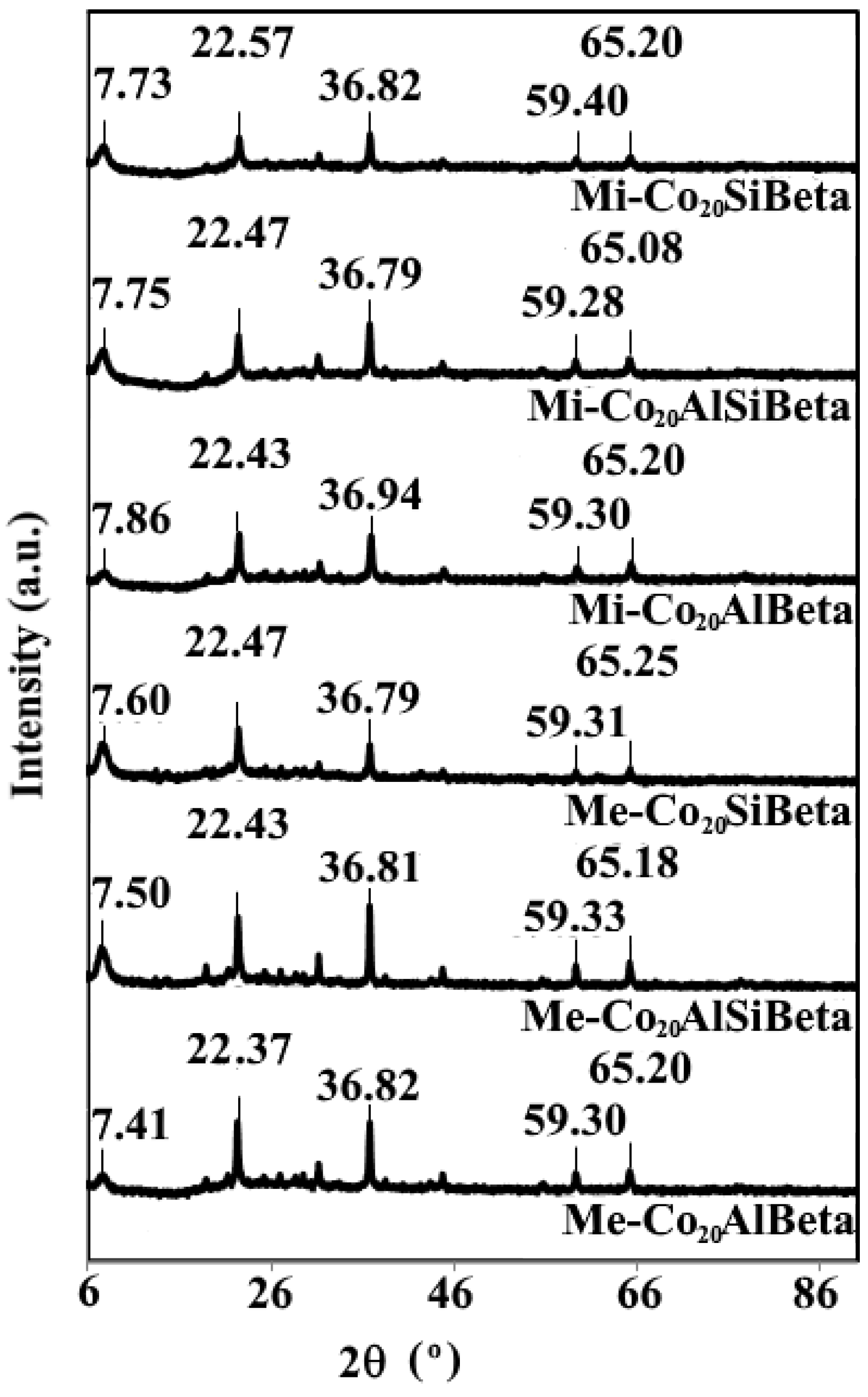
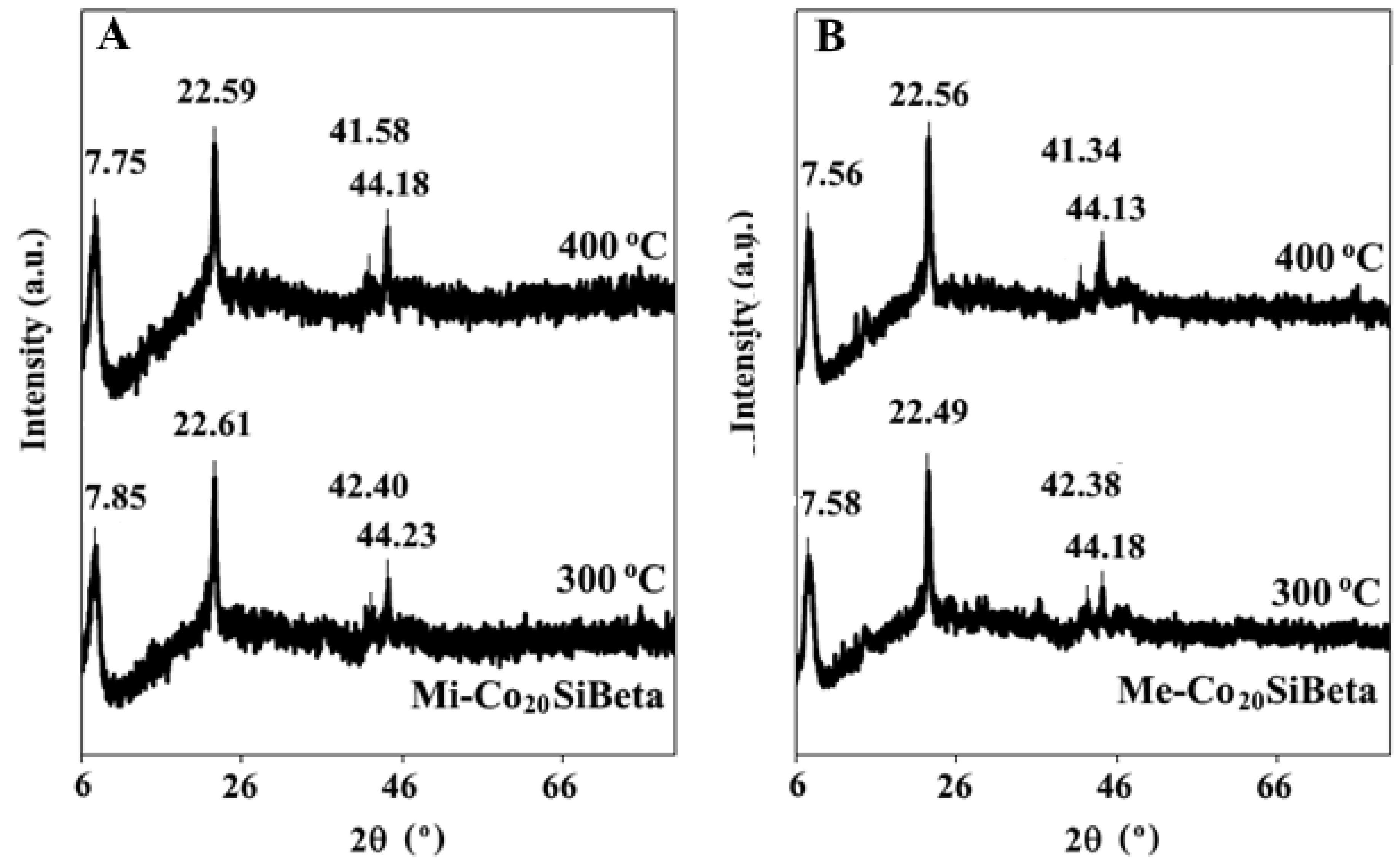
2.1. Structural Properties
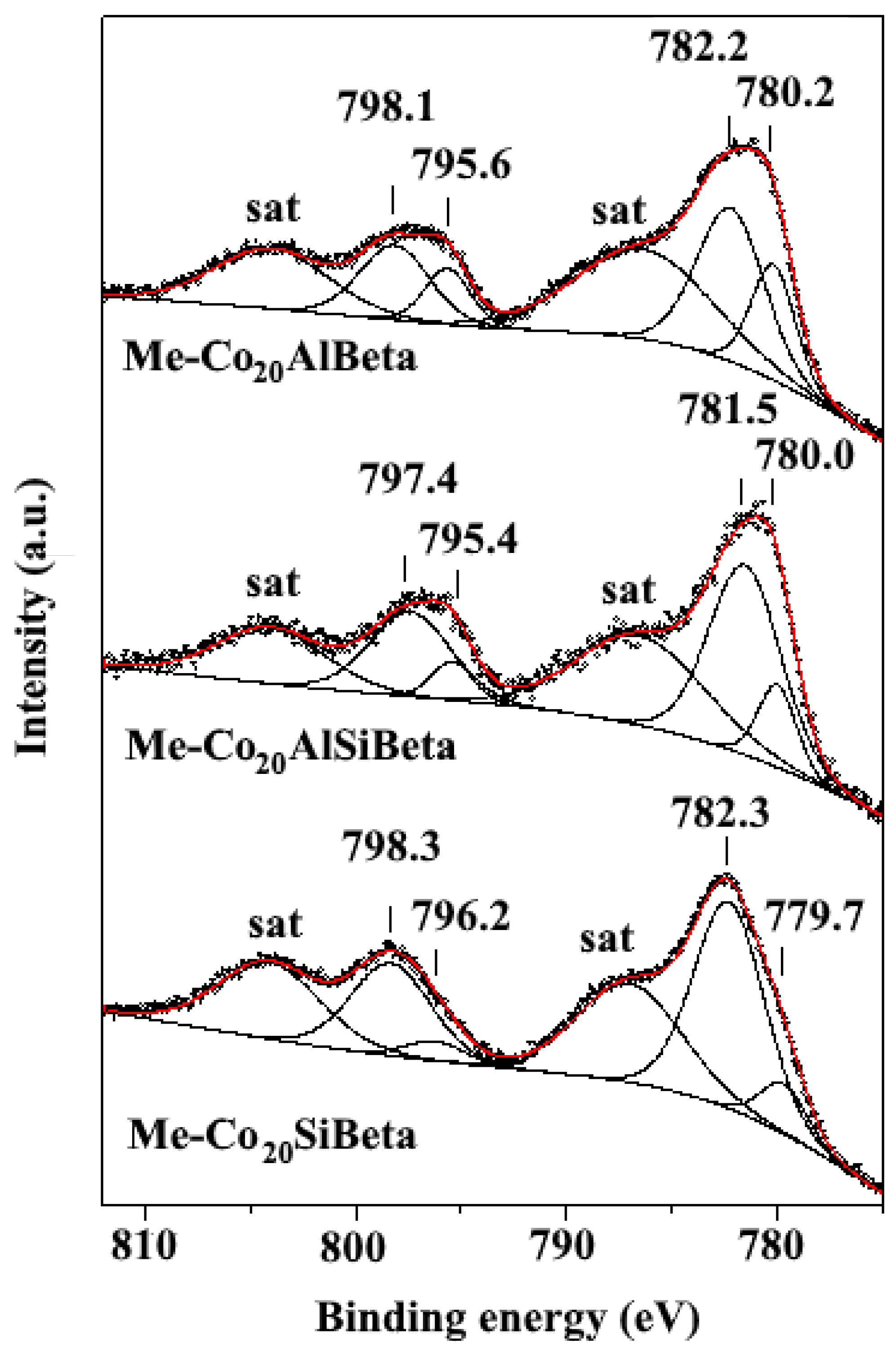
2.2. Characterisation of Zeolite Catalysts by XPS
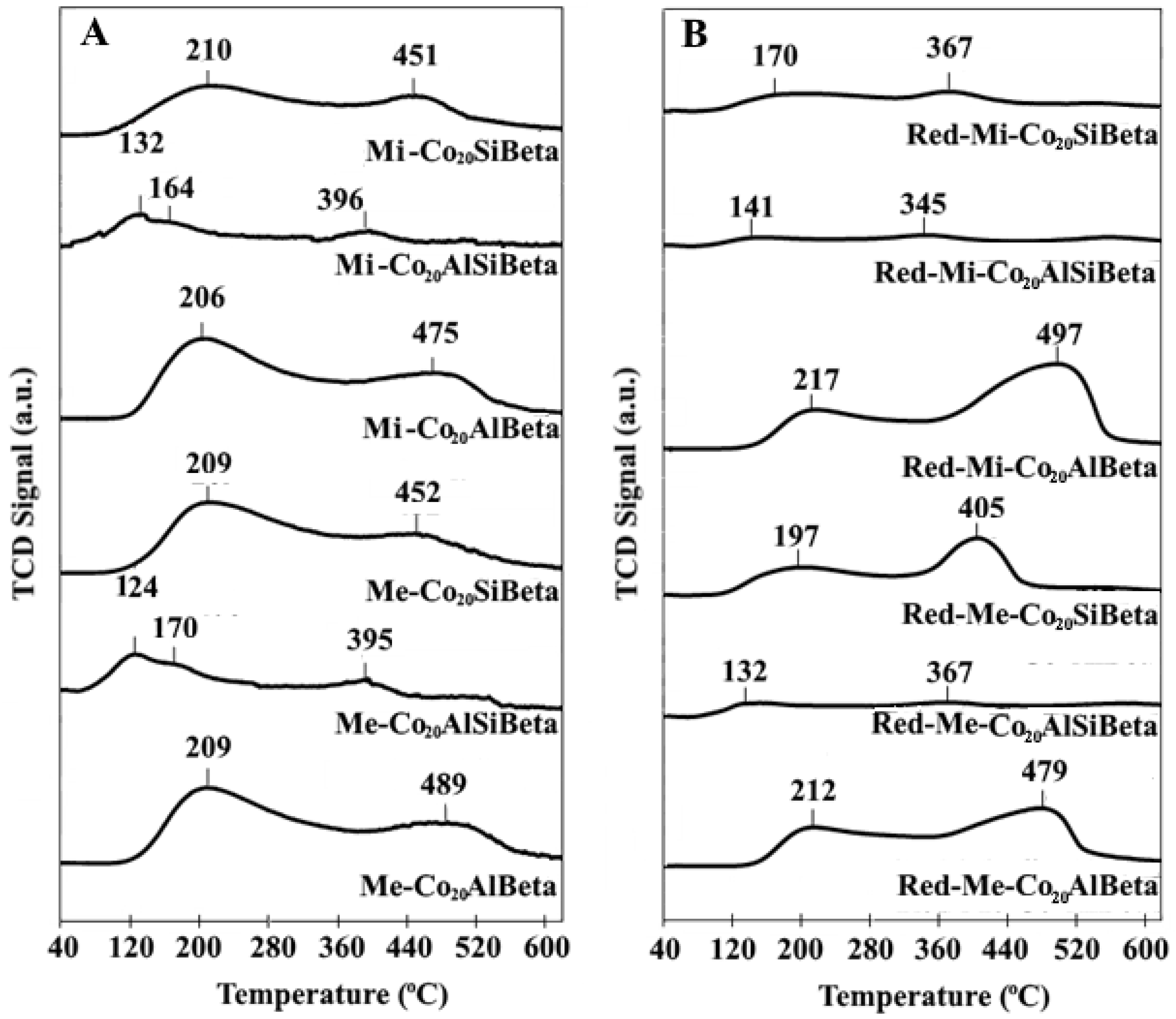
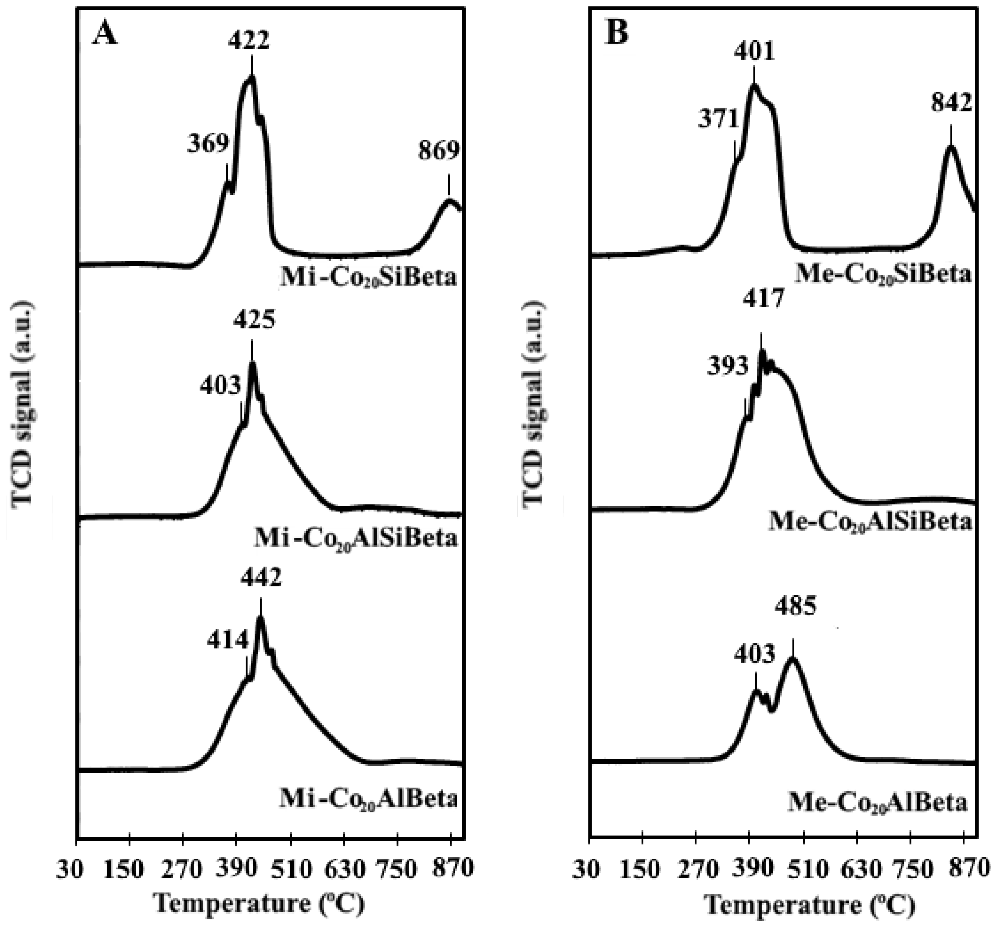
2.3. Characterisation of Acidity by NH3-TPD
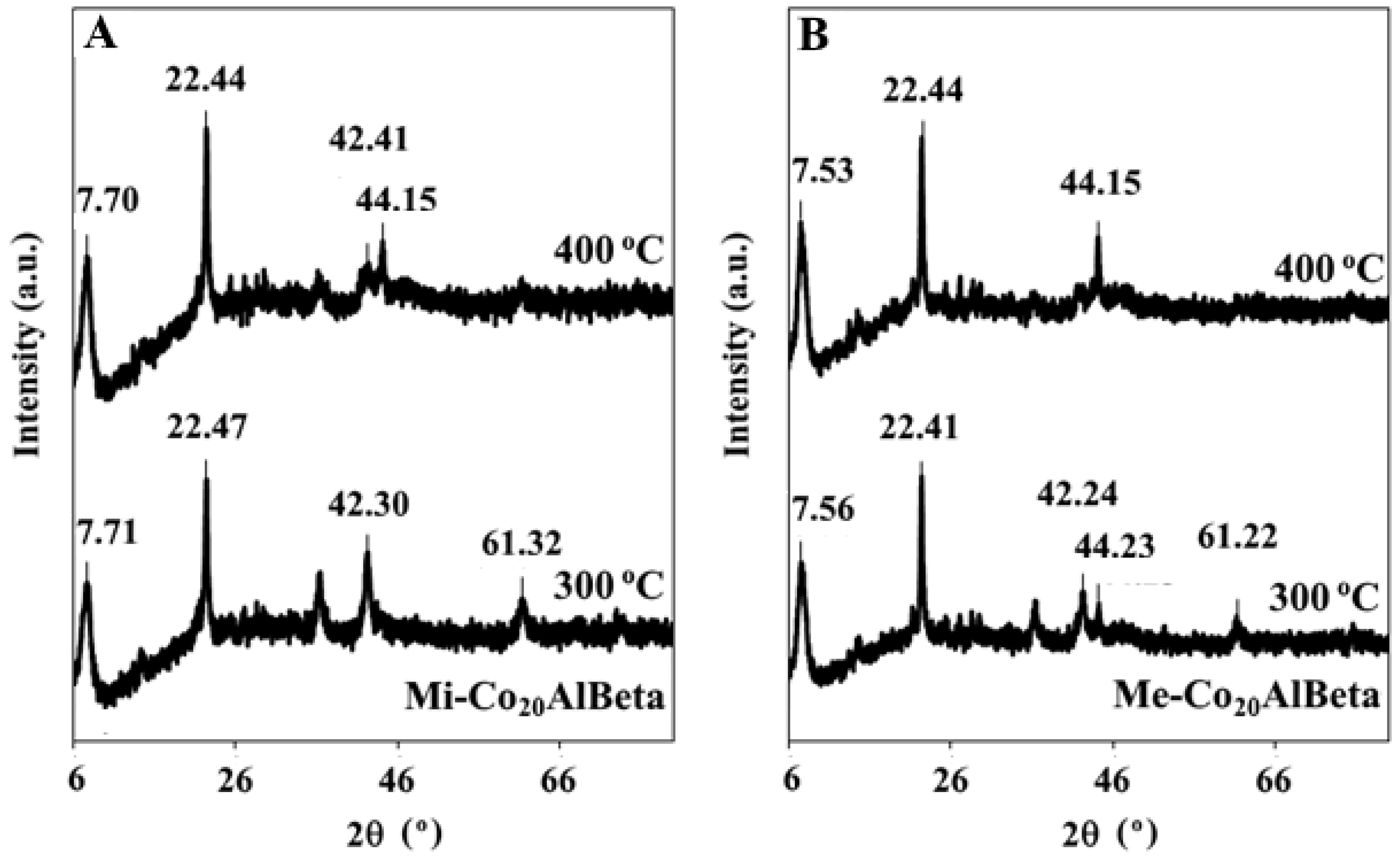
2.4. Reducibility of CoSiBeta Catalysts
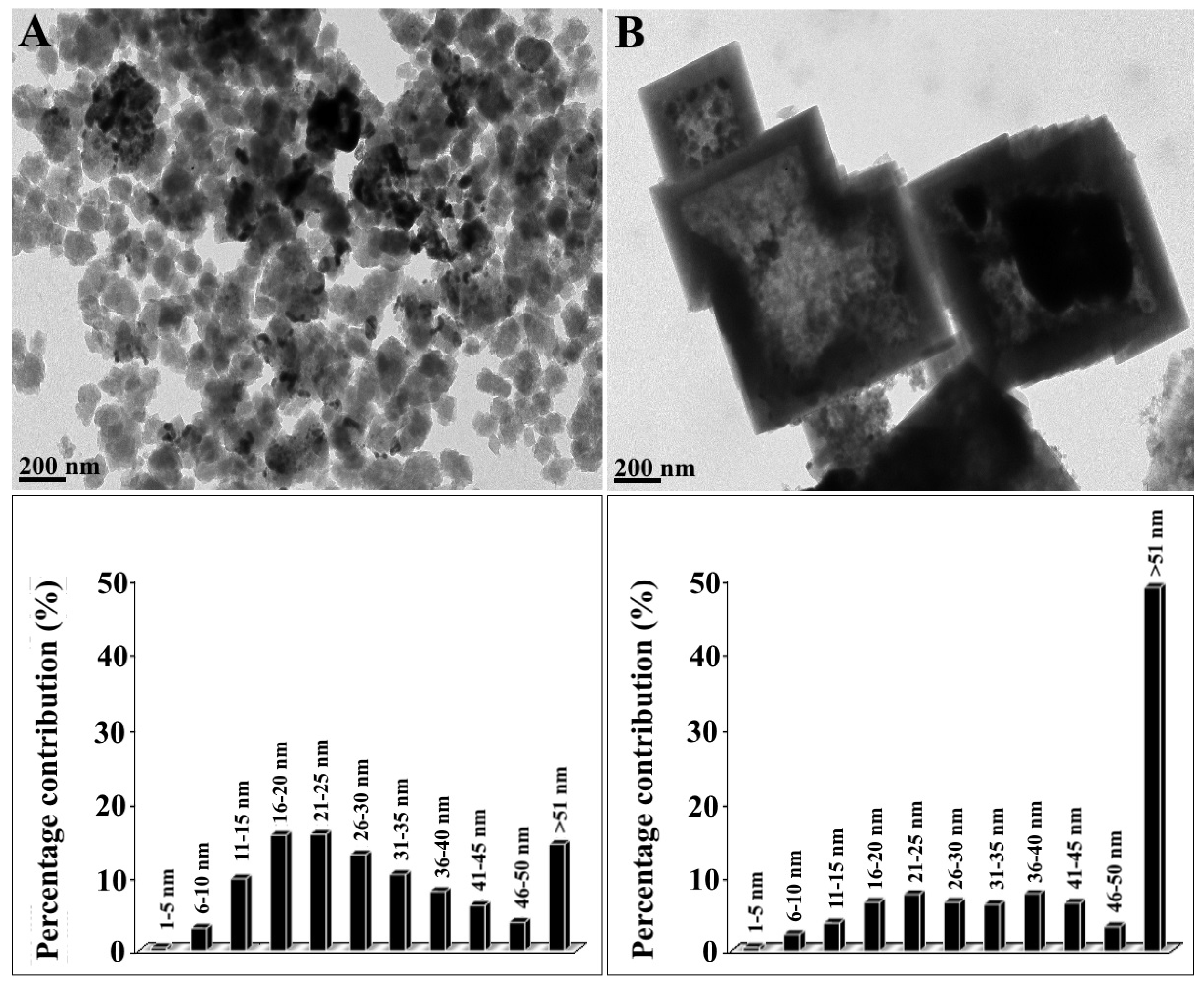
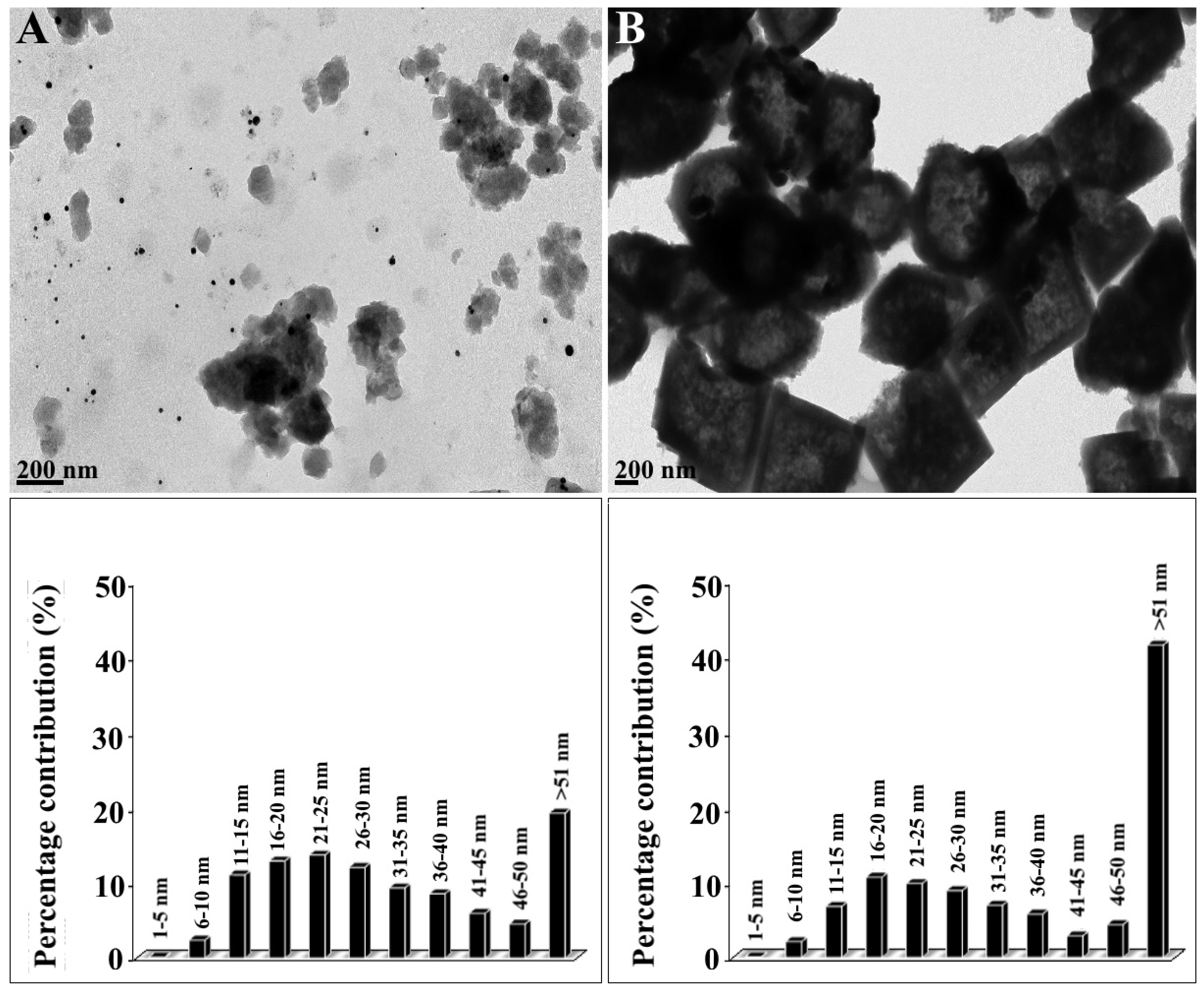
2.5. Characterisation of Cobalt Nanoparticles by TEM
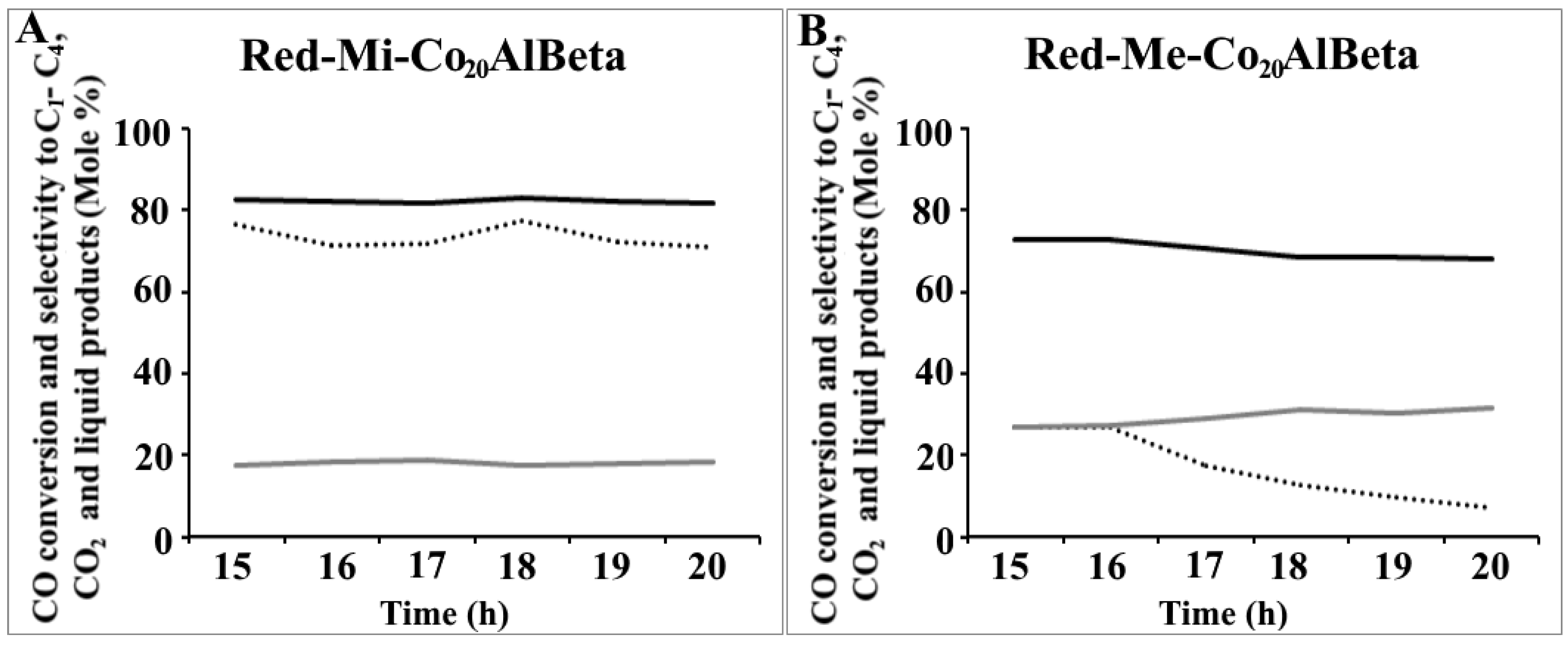
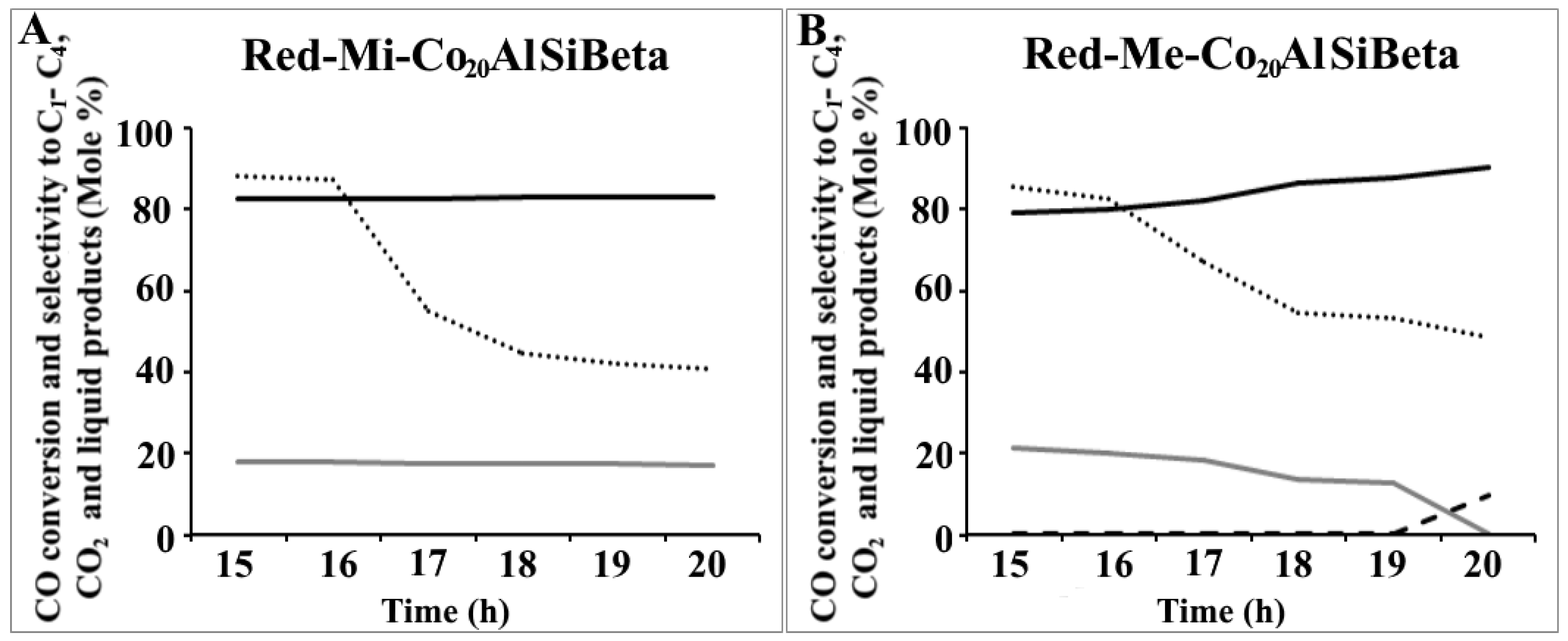
2.6. Catalytic Activity in Fischer-Tropsch Synthesis
3. Materials and Methods
- Column temperature–45 °C
- Detector temperature–120 °C
- Injector temperature–120 °C
4. Conclusions
- The presence of mesopores in the zeolite structure leads to the formation of catalysts with larger Co particles, the activity of which increases with the increase of cobalt nanoparticles average size.
- In the case of mesoporous catalysts the influence of the zeolite dealumination on the catalytic performance is significant. The activity of mesoporous samples in Fischer-Tropsch synthesis increases in the following order:Red-Me-Co20AlBeta < Red-Me-Co20AlSiBeta < Red-Me-Co20SiBeta.
- For microporous catalysts the dealumination does not play such significant role and the relatively high activity is observed for both not dealuminated and dealuminated catalysts. The activity changes in the following order:Red-Mi-Co20AlSiBeta <Red-Mi-Co20AlBeta < Red-Mi-Co20SiBeta.
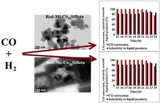
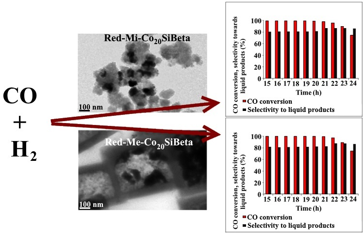
- The considerable difference in the activity between microporous not dealuminated (Red-Mi-Co20AlBeta) and mesoporous not dealuminated (Red-Me-Co20AlBeta) catalysts is found. The first of them shows much higher CO conversion (71%), selectivity towards liquid products (82%) and stability than the second one. This phenomenon may result from the less diversified metal nanoparticles distribution in mesopores samples.
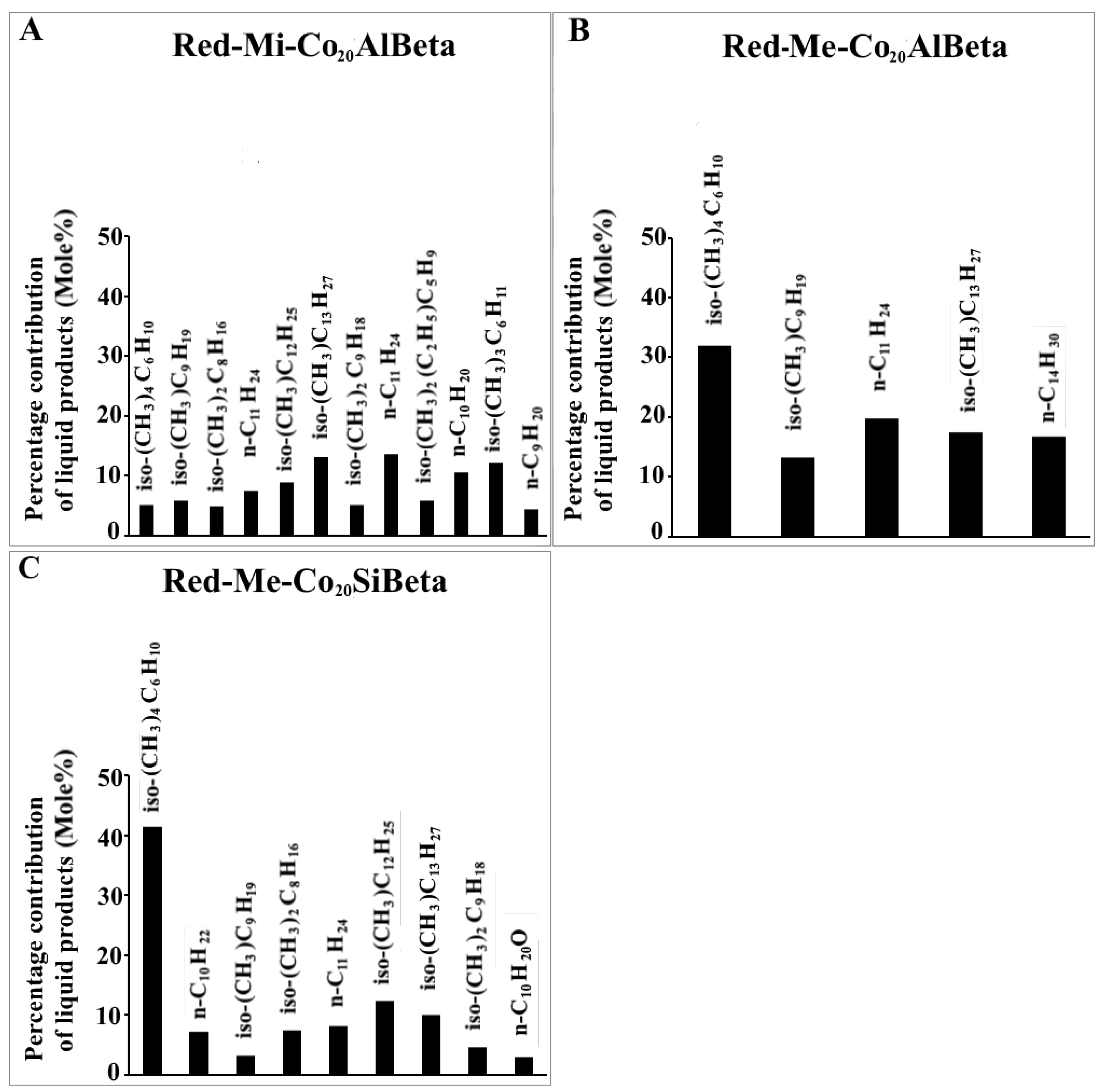
- For both mesoporous and microporous catalysts, the main liquid products are C10-C14 isoalkanes and n-alkanes. Very small amount of oxygenates (alcohols) was also identified.
- The iso-/n-alkanes ratio for catalysts supported on microporous zeolite is higher than on mesoporous one.
- The kind and amount of liquid products are related to the presence of different kind of acidic sites in dealuminated and not dealuminated zeolite catalysts.
Author Contributions
Funding
Conflicts of Interest
References
- Jung, J.S.; Kim, S.W.; Moon, D.J. Fischer–Tropsch Synthesis over cobalt based catalyst supported on different mesoporous silica. Catal. Today 2012, 185, 168–174. [Google Scholar] [CrossRef]
- Najafabadi, A.T.; Khodadadi, A.A.; Parnian, M.J.; Mortazavi, Y. Atomic layer deposited Co/γ-Al2O3 catalyst with enhanced cobalt dispersion and Fischer–Tropsch synthesis activity and selectivity. Appl. Catal. A. 2016, 511, 31–46. [Google Scholar] [CrossRef]
- Martínez, A.; López, C.; Márquez, F.; Díaz, I. Fischer–Tropsch synthesis of hydrocarbons over mesoporous Co/SBA-15 catalysts: The influence of metal loading, cobalt precursor, and promoters. J. Catal. 2003, 220, 486–499. [Google Scholar] [CrossRef]
- Khodakov, A.Y.; Griboval-Constant, A.; Bechara, R.; Zholobenko, V.L. Pore Size Effects in Fischer Tropsch Synthesis over Cobalt-Supported Mesoporous Silicas. J. Catal. 2002, 206, 230–241. [Google Scholar] [CrossRef]
- Xiong, H.; Zhang, Y.; Liew, K.; Li, J. Fischer–Tropsch synthesis: The role of pore size for Co/SBA-15 catalysts. J. Mol. Catal. A Chem. 2008, 295, 68–76. [Google Scholar] [CrossRef]
- Dalil, M.; Sohrabi, M.; Royaee, S.J. Application of nano-sized cobalt on ZSM-5 zeolite as an active catalyst in Fischer–Tropsch synthesis. J. Ind. Eng. Chem. 2012, 18, 690–696. [Google Scholar] [CrossRef]
- Subramanian, V.; Zholobenko, V.L.; Cheng, K.; Lancelot, C.; Heyte, S.; Thuriot, J.; Paul, S.; Ordomsky, V.V.; Khodakov, A.Y. The Role of Steric Effects and Acidity in the Direct Synthesis of iso-Paraffins from Syngas on Cobalt Zeolite Catalysts. ChemCatChem 2016, 8, 380–389. [Google Scholar] [CrossRef]
- Baranak, M.; Gürünlü, B.; Saıoğlan, A.; Ataç, Ö.; Atakül, H. Low acidity ZSM-5 supported iron catalysts for Fischer–Tropsch synthesis. Catal. Today 2013, 207, 57–64. [Google Scholar] [CrossRef]
- Li, C.; Sayaka, I.; Chisato, F.; Fuijmoto, K. Development of high performance graphite-supported iron catalyst for Fischer–Tropsch synthesis. Appl. Catal. A 2016, 509, 123–129. [Google Scholar] [CrossRef]
- Wang, S.; Yin, Q.; Guo, J.; Ru, B.; Zhu, L. Improved Fischer–Tropsch synthesis for gasoline over Ru, Ni promoted Co/HZSM-5 catalysts. Fuel 2013, 108, 597–603. [Google Scholar] [CrossRef]
- Jahangiri, H.; Bennett, J.; Mahjoubi, P.; Wilson, K.; Gu, S. A review of advanced catalyst development for Fischer–Tropsch synthesis of hydrocarbons from biomass derived syn-gas. Catal. Sci. Technol. 2014, 4, 2210–2229. [Google Scholar] [CrossRef]
- Kang, S.-H.; Ryu, J.-H.; Kim, J.-H.; Prasad, P.S.S.; Bae, J.W.; Cheon, J.-Y.; Jun, K.-W. ZSM-5 Supported Cobalt Catalyst for the Direct Production of Gasoline Range Hydrocarbons by Fischer–Tropsch Synthesis. Catal. Lett. 2011, 141, 1464–1471. [Google Scholar] [CrossRef]
- Wang, Y.; Jiang, Y.; Huang, J.; Liang, J.; Wang, H.; Li, Z.; Wu, J.; Li, M.; Zhao, Y.; Niu, J. Effect of hierarchical crystal structures on the properties of cobalt catalysts for Fischer–Tropsch synthesis. Fuel 2016, 174, 17–24. [Google Scholar] [CrossRef]
- Xing, C.; Yang, G.; Wu, M.; Yang, R.; Tan, L.; Zhu, P.; Wei, Q.; Li, J.; Mao, J.; Yoneyama, Y.; et al. Hierarchical zeolite Y supported cobalt bifunctional catalyst for facilely tuning the product distribution of Fischer–Tropsch synthesis. Fuel 2015, 148, 48–57. [Google Scholar] [CrossRef]
- Botes, F.G.; Böhringer, W. The addition of HZSM-5 to the Fischer–Tropsch process for improved gasoline production. Appl. Catal. A 2004, 267, 217–225. [Google Scholar] [CrossRef]
- Chalupka, K.A.; Casale, S.; Zurawicz, E.; Rynkowski, J.; Dzwigaj, S. The remarkable effect of the preparation procedure on the catalytic activity of CoBEA zeolites in the Fischer–Tropsch synthesis. Microporous Mesoporous Mater. 2015, 211, 9–18. [Google Scholar] [CrossRef]
- Concepción, P.; López, C.; Martínez, A.; Puntes, V.F. Characterization and catalytic properties of cobalt supported on delaminated ITQ-6 and ITQ-2 zeolites for the Fischer–Tropsch synthesis reaction. J. Catal. 2004, 228, 321–332. [Google Scholar] [CrossRef]
- Prieto, G.; Martínez, A.; Concepción, P.; Moreno-Tost, R. Cobalt particle size effects in Fischer–Tropsch synthesis: Structural and in situ spectroscopic characterisation on reverse micelle-synthesised Co/ITQ-2 model catalysts. J. Catal. 2009, 266, 129–144. [Google Scholar] [CrossRef]
- Newsam, J.M.; Treacy, M.M.J.; Koetsier, W.T.; Gruyter, C.B. Structural characterization of zeolite beta. Proc. R. Soc. Lond. Ser. A 1988, 420, 375–405. [Google Scholar] [CrossRef]
- Dzwigaj, S.; Janas, J.; Machej, T.; Che, M. Selective catalytic reduction of NO by alcohols on Co- and Fe-Siβ catalysts. Catal. Today 2007, 119, 133–136. [Google Scholar] [CrossRef]
- Dzwigaj, S.; Millot, Y.; Méthivier, C.; Che, M. Incorporation of Nb(V) into BEA zeolite investigated by XRD, NMR, IR, DR UV–vis, and XPS. Microporous Mesoporous Mater. 2010, 130, 162–166. [Google Scholar] [CrossRef]
- Wang, H.; Li, B.; Lu, X.-B.; LI, C.-Q.; Ding, F.-C.; Song, Y.-J. Selective catalytic reduction of NO by methane over the Co/MOR catalysts in the presence of oxygen. J. Fuel Chem. Technol. 2015, 43, 1106–1112. [Google Scholar] [CrossRef]
- Shi, L.; Tao, K.; Kawabata, T.; Shimamura, T.; Zhang, X.J.; Tsubaki, N. Surface Impregnation Combustion Method to Prepare Nanostructured Metallic Catalysts without Further Reduction: As-Burnt Co/SiO2 Catalysts for Fischer–Tropsch Synthesis. ACS Catal. 2011, 1, 1225–1233. [Google Scholar] [CrossRef]
- Khemtong, P.; Klysubun, W.; Prayoonpokarach, S.; Wittayakun, J. Reducibility of cobalt species impregnated on NaY and HY zeolites. Mater. Chem. Phys. 2010, 121, 131–137. [Google Scholar] [CrossRef]
- Khodakov, A.Y.; Lynch, J.; Bazin, D.; Rebours, B.; Zanier, N.; Moisson, B.; Chaumette, P. Reducibility of Cobalt Species in Silica-Supported Fischer–Tropsch Catalysts. J. Catal. 1997, 168, 16–25. [Google Scholar] [CrossRef]
- Kumar, M.S.; Schwidder, M.; Grünert, W.; Bentrup, U.; Brückner, A. Selective reduction of NO with Fe-ZSM-5 catalysts of low Fe content: Part II. Assessing the function of different Fe sites by spectroscopic in situ studies. J. Catal. 2006, 239, 173–186. [Google Scholar]
- Arishtirova, K.; Kovacheva, P.; Predoeva, A. Activity and basicity of BaO modified zeolite and zeolite-type catalysts. Appl. Catal. A 2003, 243, 191–196. [Google Scholar] [CrossRef]
- Kovacheva, P.; Arishtirova, K.; Predoeva, A. Basic zeolite and zeolite-type catalysts for the oxidative methylation of toluene with methane. React. Kinet. Catal. Lett. 2003, 79, 149–155. [Google Scholar] [CrossRef]
- Oleksenko, L.P. Characteristics of Active Site Formation in Co-Containing Catalysts for CO Oxidation on Chemically Different Supports. Theor. Exp. Chem. 2004, 40, 331–336. [Google Scholar] [CrossRef]
- Grünert, W.; Schlögl, R. Photoelectron Spectroscopy of Zeolites. Mol. Sieves 2004, 4, 467–515. [Google Scholar]
- Kocemba, I.; Rynkowski, J.; Gurgul, J.; Socha, R.P.; Łątka, K.; Krafft, J.-M.; Dzwigaj, S. Nature of the active sites in CO oxidation on FeSiBEA zeolites. Appl. Catal. A 2016, 519, 16–26. [Google Scholar] [CrossRef]
- Boroń, P.; Chmielarz, L.; Gurgul, J.; Łątka, K.; Gil, B.; Marszałek, B.; Dzwigaj, S. Influence of iron state and acidity of zeolites on the catalytic activity of FeHBEA, FeHZSM-5 and FeHMOR in SCR of NO with NH3 and N2O decomposition. Microporous Mesoporous Mater. 2015, 203, 73–85. [Google Scholar] [CrossRef]
- Janas, J.; Gurgul, J.; Socha, R.P.; Dzwigaj, S. Effect of Cu content on the catalytic activity of CuSiBEA zeolite in the SCR of NO by ethanol: Nature of the copper species. Appl. Catal. B 2009, 91, 217–224. [Google Scholar] [CrossRef]
- Boroń, P.; Chmielarz, L.; Gurgul, J.; Łątka, K.; Shishido, T.; Krafft, J.-M.; Dzwigaj, S. BEA zeolite modified with iron as effective catalyst for N2O decomposition and selective reduction of NO with ammonia. Appl. Catal. B 2013, 138–139, 434–445. [Google Scholar] [CrossRef]
- NIST X-ray Photoelectron Spectroscopy Database. Available online: http://srdata.nist.gov/xps/ (accessed on 13 September 2018).
- Chen, H.-H.; Shen, S.-C.; Chen, X.; Kawi, S. Selective catalytic reduction of NO over Co/beta-zeolite: Effects of synthesis condition of beta-zeolites, Co precursor, Co loading method and reductant. Appl. Catal. B 2004, 50, 37–47. [Google Scholar] [CrossRef]
- Zsoldos, Z.; Vass, G.; Lu, G.; Guczi, L. XPS study on the effects of treatments on Pt2+ and Co2+ exchanged into NaY zeolite. Appl. Surf. Sci. 1994, 78, 467–475. [Google Scholar] [CrossRef]
- Boix, A.V.; Zamaro, J.M.; Lombardo, E.A.; Miro, E.E. The beneficial effect of silica on the activity and thermal stability of PtCoFerrierite-washcoated cordierite monoliths for the SCR of NOx with CH4. Appl. Catal. B 2003, 46, 121–132. [Google Scholar] [CrossRef]
- Da Cruz, R.S.; Mascarenhas, A.J.S.; Andrade, H.M.C. Co-ZSM-5 catalysts for N2O decomposition. Appl. Catal. B 1998, 18, 223–231. [Google Scholar] [CrossRef]
- Stencel, J.M.; Rao, V.U.S.; Diehl, J.R.; Rhee, K.H.; Dhere, A.G.; De Angelis, R.J. Dual cobalt speciation in CoZSM-5 catalysts. J. Catal. 1983, 84, 109–118. [Google Scholar] [CrossRef]
- Dzwigaj, S.; Janas, J.; Mizera, J.; Gurgul, J.; Socha, R.P.; Che, M. Incorporation of Copper in SiBEA Zeolite as Isolated Lattice Mononuclear Cu(II) Species and its Role in Selective Catalytic Reduction of NO by Ethanol. Catal. Lett. 2008, 126, 36–42. [Google Scholar] [CrossRef]
- Janas, J.; Gurgul, J.; Socha, R.P.; Shishido, T.; Che, M.; Dzwigaj, S. Selective catalytic reduction of NO by ethanol: Speciation of iron and “structure–properties” relationship in FeSiBEA zeolite. Appl. Catal. B 2009, 91, 113–122. [Google Scholar] [CrossRef]
- Janas, J.; Gurgul, J.; Socha, R.P.; Kowalska, J.; Nowinska, K.; Shishido, T.; Che, M.; Dźwigaj, S. Influence of the Content and Environment of Chromium in CrSiBEA Zeolites on the Oxidative Dehydrogenation of Propane. J. Phys. Chem. C 2009, 113, 13273–13281. [Google Scholar] [CrossRef]
- Sartipi, S.; Parashar, K.; Valero-Romero, M.J.; Santos, V.P.; van der Linden, B.; Makkee, M.; Kapteijn, F.; Gascon, J. Hierarchical H-ZSM-5-supported cobalt for the direct synthesis of gasoline-range hydrocarbons from syngas: Advantages, limitations, and mechanistic insight. J. Catal. 2013, 305, 179–190. [Google Scholar] [CrossRef]
- Boroń, P.; Chmielarz, L.; Casal, S.; Calers, C.; Krafft, J.-M.; Dzwigaj, S. Effect of Co content on the catalytic activity of CoSiBEA zeolites in N2O decomposition and SCR of NO with ammonia. Catal. Today 2015, 258, 507–517. [Google Scholar] [CrossRef]
- Karimi, S.; Tavasoli, A.; Mortazavi, Y.; Karimi, A. Enhancement of cobalt catalyst stability in Fischer–Tropsch synthesis using graphene nanosheets as catalyst support. Chem. Eng. Res. Des. 2015, 104, 713–722. [Google Scholar] [CrossRef]
- Tavasoli, A.; Malek Abbaslou, R.M.; Dalai, A.K. Deactivation behavior of ruthenium promoted Co/γ-Al2O3 catalysts in Fischer–Tropsch synthesis. Appl. Catal. A 2008, 346, 58–64. [Google Scholar] [CrossRef]
- Sartipi, S.; Parashar, K.; Makkee, M.; Gascon, J.; Kapteijn, F. Breaking the Fischer–Tropsch synthesis selectivity: Direct conversion of syngas to gasoline over hierarchical Co/H-ZSM-5 catalysts. Catal. Sci. Technol. 2013, 3, 572–575. [Google Scholar] [CrossRef]
- Martinez, A.; Lopez, C. The influence of ZSM-5 zeolite composition and crystal size on the in situ conversion of Fischer–Tropsch products over hybrid catalysts. Appl. Catal. A 2005, 294, 251–259. [Google Scholar] [CrossRef]
- Peña, D.; Griboval-Constant, A.; Lancelot, C.; Quijada, M.; Visez, N.; Stéphan, O.; Lecocq, V.; Diehl, F.; Khodakov, A.Y. Molecular structure and localization of carbon species in alumina supported cobalt Fischer–Tropsch catalysts in a slurry reactor. Catal. Today 2014, 228, 65–76. [Google Scholar] [CrossRef]
- Moodley, D.J.; van de Loosdrecht, J.; Saib, A.M.; Overett, M.J.; Datye, A.K.; Niemantsverdriet, J.W. Carbon deposition as a deactivation mechanism of cobalt-based Fischer–Tropsch synthesis catalysts under realistic conditions. Appl. Catal. A Gen. 2009, 354, 102–110. [Google Scholar] [CrossRef]
- Bartholomew, C.H.; Farrauto, R.J. Fundamentals of Industrial Catalytic Processes, 2nd ed.; Chapter 5; Wiley Interscience: New York, NY, USA, 2010; pp. 260–336. [Google Scholar]


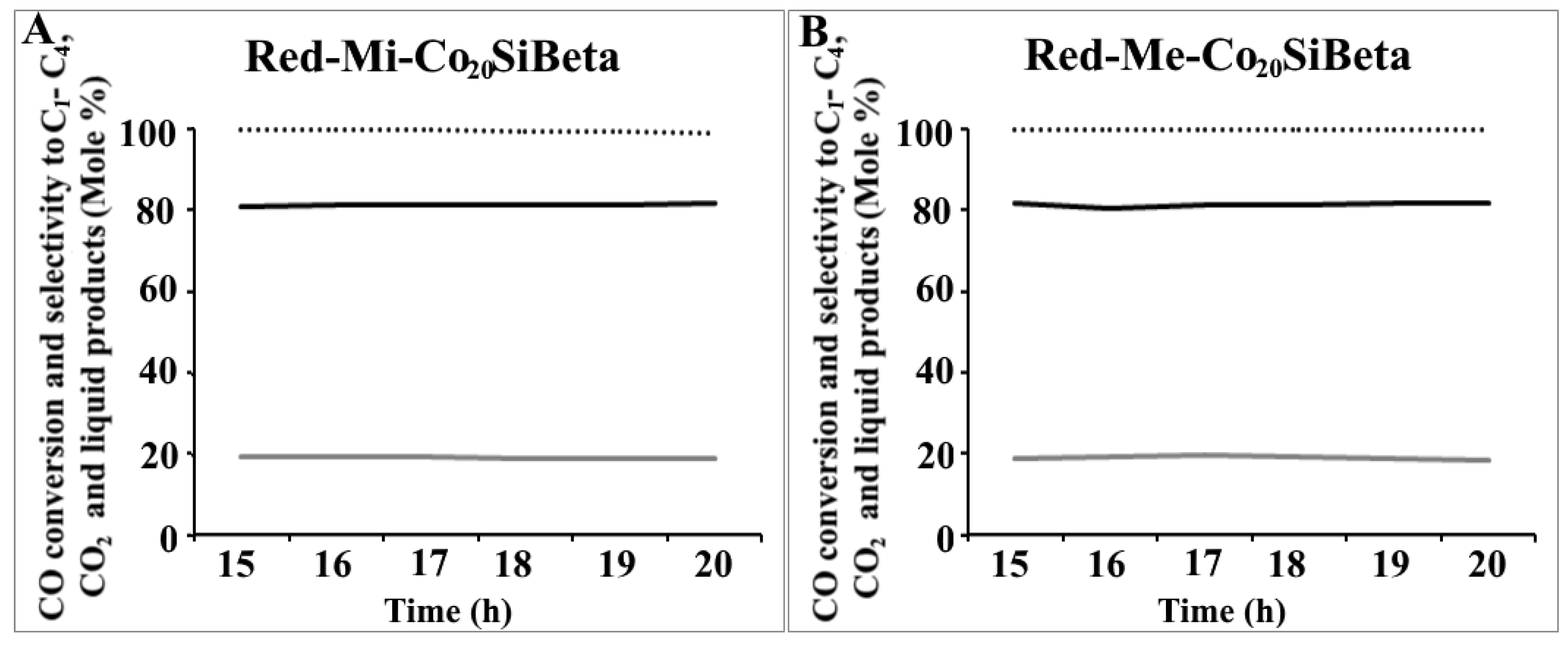
 ) and selectivity towards C1-C4 (
 ) and liquid products (
 ) up to 20 h of reaction at 260°C and 30 atm on (A) Red-Mi-Co20AlBeta and (B) Red-Me-Co20AlBeta.
) and selectivity towards C1-C4 () and liquid products () up to 20 h of reaction at 260°C and 30 atm on (A) Red-Mi-Co20AlBeta and (B) Red-Me-Co20AlBeta.
) up to 20 h of reaction at 260°C and 30 atm on (A) Red-Mi-Co20AlBeta and (B) Red-Me-Co20AlBeta.
) and selectivity towards C1-C4 () and liquid products () up to 20 h of reaction at 260°C and 30 atm on (A) Red-Mi-Co20AlBeta and (B) Red-Me-Co20AlBeta. ) and selectivity towards C1-C4 (), CO2 (
 ) and liquid products () up to 20 h of reaction at 260 °C and 30 atm on (A) Red-Mi-Co20AlSiBeta and (B) Red-Me-Co20AlSiBeta.
) and selectivity towards C1-C4 (), CO2 () and liquid products () up to 20 h of reaction at 260 °C and 30 atm on (A) Red-Mi-Co20AlSiBeta and (B) Red-Me-Co20AlSiBeta.
) and liquid products () up to 20 h of reaction at 260 °C and 30 atm on (A) Red-Mi-Co20AlSiBeta and (B) Red-Me-Co20AlSiBeta.
) and selectivity towards C1-C4 (), CO2 () and liquid products () up to 20 h of reaction at 260 °C and 30 atm on (A) Red-Mi-Co20AlSiBeta and (B) Red-Me-Co20AlSiBeta. ) and selectivity towards C1-C4 () and liquid products () up to 20 h of reaction at 260°C and 30 atm on (A) Red-Mi-Co20SiBeta and (B) Red-Me-Co20SiBeta.
) and selectivity towards C1-C4 () and liquid products () up to 20 h of reaction at 260°C and 30 atm on (A) Red-Mi-Co20SiBeta and (B) Red-Me-Co20SiBeta.
) and selectivity towards C1-C4 () and liquid products () up to 20 h of reaction at 260°C and 30 atm on (A) Red-Mi-Co20SiBeta and (B) Red-Me-Co20SiBeta.


| Zeolites | A | A′ | B | B′ | Satellite | Satellite |
|---|---|---|---|---|---|---|
| Me-Co20AlBeta | 780.2 (29.5) | 795.6 | 782.3 (70.5) | 798.0 | 787.1 | 804.0 |
| Mi-Co20AlBeta | 779.9 (34.2) | 795.6 | 782.5 (65.8) | 798.7 | 786.8 | 804.4 |
| Me-Co20AlSiBeta | 780.0 (31.1) | 795.4 | 781.8 (68.9) | 797.6 | 786.4 | 803.9 |
| Mi-Co20AlSiBeta | 779.5 (24.4) | 796.3 | 782.3 (75.6) | 798.4 | 786.3 | 803.9 |
| Me-Co20SiBeta | 779.7 (16.1) | 796.2 | 782.3 (83.9) | 798.3 | 786.9 | 804.1 |
| Mi-Co20SiBeta | --- | --- | 782.4 (100) | 798.5 | 787.7 | 804.5 |
| Sample | NH3 [μmol/g] | Average Crystallites Size [nm] |
|---|---|---|
| Me-Co20SiBeta | 1202 | |
| Red-Me-Co20SiBeta | 1178 | 80.0 |
| Me-Co20AlSiBeta | 522 | |
| Red-Me-Co20AlSiBeta | 301 | 68.3 |
| Me-Co20AlBeta | 1316 | |
| Red-Me-Co20AlBeta | 1741 | 37.2 |
| Mi-Co20SiBeta | 915 | |
| Red-Mi-Co20SiBeta | 647 | 51.9 |
| Mi-Co20AlSiBeta | 253 | |
| Red-Mi-Co20AlSiBeta | 220 | 45.0 |
| Mi-Co20AlBeta | 1442 | |
| Red-Mi-Co20AlBeta | 2279 | 34.1 |
| Catalysts | CO Conversion [Mole%] | Selectivity Towards C1-C4 and CO2 [Mole%] | Selectivity towards Liquid Products [Mole%] | iso/n-Alkane Ratio | Alcohols/n-Alkane Ratio | Unsaturated/n-Alkane Ratio | α C5+ |
|---|---|---|---|---|---|---|---|
| Red-Mi-Co20AlBeta | 70.81 | 18.30 | 81.70 | 2.21 | - | 0.54 | 0.76 |
| Red-Mi-Co20AlSiBeta | 40.85 | 17.08 | 82.92 | ||||
| Red-Mi-Co20SiBeta | 98.97 | 18.61 | 81.39 | ||||
| Red-Me-Co20AlBeta | 7.12 | 31.74 | 68.26 | 1.79 | - | 0.45 | 0.91 |
| Red-Me-Co20AlSiBeta | 48.52 | 9.44 | 87.56 | ||||
| Red-Me-Co20SiBeta | 99.56 | 18.27 | 81.74 | 1.48 | 0.21 | 0.46 | 0.63 |
| Sample | Reaction Time (h) | C1 (nC=1nC1) | C2 (nC=2nC2) | C3 (nC=3nC3) | C4 (nC=4nC4) | CO2 | CO outlet | Total outlet |
|---|---|---|---|---|---|---|---|---|
| Red-Mi- Co20AlBeta | 15 | 0.00012 | 0.000034 | 0.000012 | 0.0000093 | 0 | 0.00018 | 0.00035 |
| 20 | 0.000034 | 0.000202 | 0.000039 | 0.000009 | 0 | 0.000240 | 0.00052 | |
| Red-Me- Co20AlBeta | 15 | 0.000090 | 0.00016 | 0.000014 | 0.0000068 | 0 | 0.00047 | 0.00074 |
| 20 | 0.000093 | 0.000324 | 0.000007 | 0.000014 | 0 | 0.000793 | 0.00120 | |
| Red-Me- Co20SiBeta | 15 | 0.000080 | 0.00015 | 0.0000039 | 0.0000035 | 0 | 0,0000025 | 0.00024 |
| 20 | 0.000070 | 0.000157 | 0.000002 | 0.000004 | 0 | 0.000004 | 0.00024 |
© 2019 by the authors. Licensee MDPI, Basel, Switzerland. This article is an open access article distributed under the terms and conditions of the Creative Commons Attribution (CC BY) license (http://creativecommons.org/licenses/by/4.0/).
Share and Cite
Sadek, R.; Chalupka, K.A.; Mierczynski, P.; Rynkowski, J.; Gurgul, J.; Dzwigaj, S. Cobalt Based Catalysts Supported on Two Kinds of Beta Zeolite for Application in Fischer-Tropsch Synthesis. Catalysts 2019, 9, 497. https://doi.org/10.3390/catal9060497
Sadek R, Chalupka KA, Mierczynski P, Rynkowski J, Gurgul J, Dzwigaj S. Cobalt Based Catalysts Supported on Two Kinds of Beta Zeolite for Application in Fischer-Tropsch Synthesis. Catalysts. 2019; 9(6):497. https://doi.org/10.3390/catal9060497
Chicago/Turabian StyleSadek, Renata, Karolina A. Chalupka, Pawel Mierczynski, Jacek Rynkowski, Jacek Gurgul, and Stanislaw Dzwigaj. 2019. "Cobalt Based Catalysts Supported on Two Kinds of Beta Zeolite for Application in Fischer-Tropsch Synthesis" Catalysts 9, no. 6: 497. https://doi.org/10.3390/catal9060497
APA StyleSadek, R., Chalupka, K. A., Mierczynski, P., Rynkowski, J., Gurgul, J., & Dzwigaj, S. (2019). Cobalt Based Catalysts Supported on Two Kinds of Beta Zeolite for Application in Fischer-Tropsch Synthesis. Catalysts, 9(6), 497. https://doi.org/10.3390/catal9060497