Article

Highly Loaded Mesoporous Ni–La2O3 Catalyst Prepared by Colloidal Solution Combustion Method for CO2 Methanation

1
Department of Chemical Engineering, School of Petrochemical Technology and Energy Engineering, Zhejiang Ocean University, Zhoushan 316022, Zhejiang, China
2
School of Food and Pharmaceutical, Zhejiang Ocean University, Zhoushan 316022, Zhejiang, China
*
Author to whom correspondence should be addressed.
These authors contributed equally to this work.
Catalysts 2019, 9(5), 442; https://doi.org/10.3390/catal9050442
Submission received: 1 April 2019 / Revised: 29 April 2019 / Accepted: 7 May 2019 / Published: 11 May 2019

Abstract

:
Highly dispersed Ni-based catalysts for CO2 methanation have been extensively studied over the last decade. However, a highly loaded Ni-based catalyst always results in a large Ni particle size and poor CO2 methanation activity. In this work, a colloidal solution combustion method was used to prepare a highly loaded Ni–La2O3 catalyst (50 wt % Ni) with a small Ni particle size and abundant metal–support interface. The characterizations demonstrated that a Ni–La2O3 catalyst prepared in this way has a mesoporous structure and a small Ni particle size. Due to the small Ni particle size and abundant metal–support interface, the highly loaded mesoporous Ni–La2O3 catalyst exhibits higher activity and selectivity in CO2 methanation compared to the Ni–La2O3 catalyst prepared by a conventional solution combustion method.

Graphical Abstract

1. Introduction

CO2 emissions have increased rapidly due to the increasing consumption of fossil fuels, resulting in global warming and climate change. Various methods were proposed to convert CO2 to fuels and chemicals [1,2]. CO2 methanation is a promising reaction for converting greenhouse gas CO2 and renewable H2 into methane [3]. Moreover, the produced methane is an important chemical intermediate that can be used in chemical and petrochemical industries. CO2 methanation, commonly called the Sabatier reaction, is an exothermic reaction which is thermodynamically favored at low temperatures [3,4]. However, since CO2 molecules have high chemical inertia, the CO2 methanation reaction activity is very low at a low temperature and atmospheric pressure.
CO2 + 4H2 → CH4 + 2H2O ΔH298 K = −164.6 0 kJ mol−1
To realize low temperature CO2 methanation, various catalysts have been designed, developed, and tested for their catalytic activity at a low temperature. Many metal catalysts, such as supported Rh [5,6], Ru [7], Pd [8], Co [9,10,11], and Ni [12,13,14] catalysts, have been developed for CO2 methanation. Among the reported catalysts, supported Ni-based catalysts have been intensively studied due to their low price and high levels of activity.
To increase the low-temperature activity of Ni-based catalysts, many methods have been proposed for preparing catalysts with a small Ni particle size [15]. A general strategy for increasing the dispersion of active components involves loading the active component on a carrier with a high surface area, such as mesoporous silica [16,17,18]. However, the metal loading of a catalyst prepared using this method is low, and usually not higher than 30 wt %.
Metal loading and particle size are the two most important parameters in determining the catalytic performance for CO2 methanation. It would be ideal if the two parameters could be independently controlled. However, in reality, a catalyst with a higher loading usually has a larger particle size [19] and exhibits low activity. This interdependence between metal loading and particle size hinders the preparation of a highly active CO2 methanation catalyst with high Ni loading.
La2O3 has been widely used as a promoter or support in CO2 conversion catalysts, such as CO2 methanation and dry reforming of methane (DRM), due to its strong adsorption of CO2 [20]. Song et al. [21] reported that 10% Ni/La2O3 catalysts prepared by the impregnation method were active in CO2 methanation. Li et al. [22] reported that La2O2CO3 nanorods could be used as support precursors to Ni/La2O3 nanorod catalysts with stabilized Ni nanoparticles. LaNiO3 perovskite can be used as precursors to produce highly dispersed Ni-based catalysts. However, this requires high-temperature reduction. To the best of our knowledge, although some mesoporous supports, such as Al2O3, SiO2, and ZrO2, have been used in CO2 methanation catalysts, mesoporous Ni–La2O3 catalysts have not been reported for CO2 methanation.
Herein, a colloidal solution combustion method, which had been previously used to prepare mesoporous CeO2 and CeO2-based catalysts [23,24], was proposed to prepare highly loaded Ni on La2O3. By using this method, a highly loaded Ni–La2O3–M (~50 wt % Ni) catalyst with a small Ni particle size was synthesized. The catalyst has an abundant metal–support interface and exhibits good catalytic performance in CO2 methanation.

2. Results and Discussion

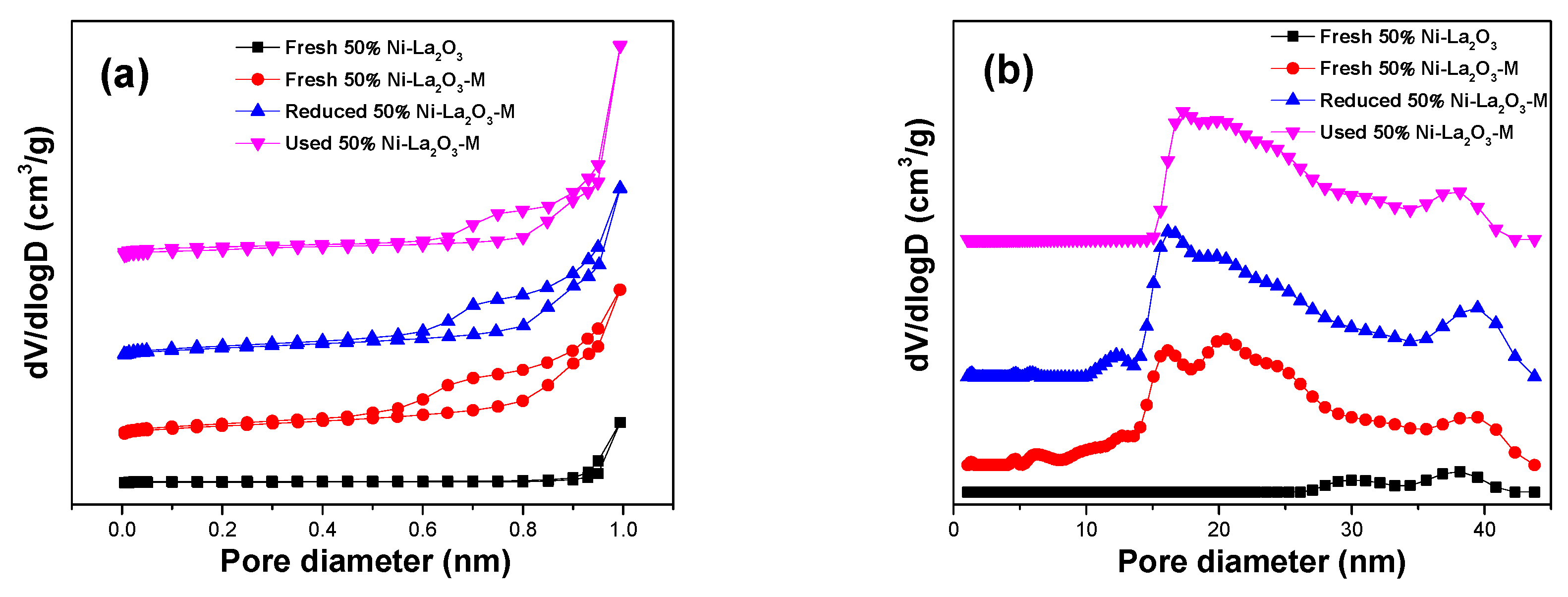
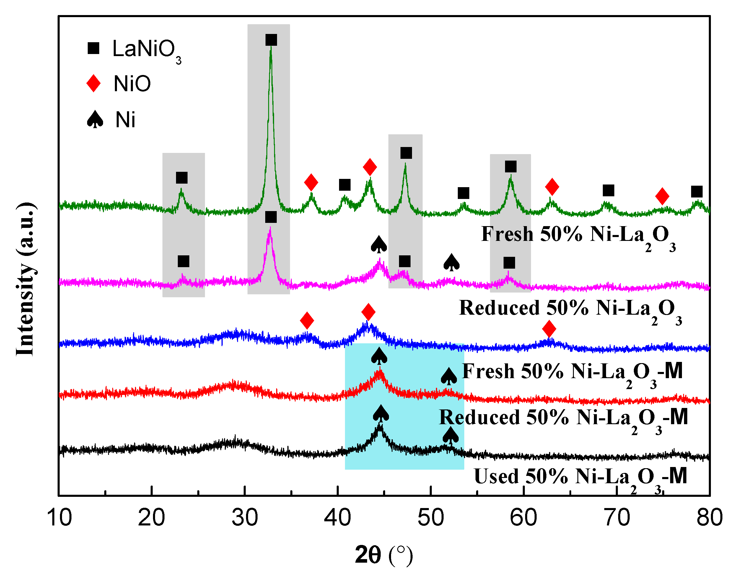
2.1. Characterization of Catalysts

N2 adsorption–desorption isotherms and pore size distribution curves of 50% Ni–La2O3–M and 50% Ni–La2O3 are shown in Figure 1. According to the International Union of Pure and Applied Chemistry (IUPAC) classification, the fresh, reduced, and used 50% Ni–La2O3–M catalysts exhibit the typical IV type isotherms which are associated with capillary condensation in mesoporous materials [25]. The result indicates that after being treated with a hot NaOH solution, SiO2 was etched and a mesoporous structure was formed. However, the fresh 50% Ni–La2O3 catalyst showed the typical III type isotherms with no inflection point on the curve, indicating weak interactions with the adsorbate of N2. Figure 1b shows that the 50% Ni–La2O3–M catalyst has a relatively narrow pore size distribution, which was concentrated at about 16–20 nm. This indicates that the catalyst has a uniform mesoporous structure.
The surface area, pore volume, and average pore size for these catalysts are listed in Table 1. It can be seen that the Brunauer–Emmett–Teller (BET) surface area of the fresh 50% Ni–La2O3–M is 70.4 m2 g−1, which is 8.8-fold higher than the fresh 50% Ni–La2O3 catalyst. The pore volume of the fresh 50% Ni–La2O3–M was higher than that of the fresh 50% Ni–La2O3 catalyst, which should have resulted from the etching of SiO2 by NaOH during the preparation process. The average pore size of 50% Ni–La2O3 catalyst was 71 nm, which indicated that the catalyst has a mainly macroporous structure. It should be noted that the average pore size of 50% Ni–La2O3 catalyst was larger than those shown in Figure 1b. This is because quenched solid density functional theory (QSDFT) is only suitable for micropore and mesoporous analysis, but not for macropore analysis [26].
After the reduction and methanation reaction, the BET surface area and average pore size of 50% Ni–La2O3–M had a slight change. In summary, the 50% Ni–La2O3–M catalyst prepared by the colloid solution combustion method formed a mesoporous structure which has a high specific surface area and pore volume.
Figure 2 presents the X-ray diffraction (XRD) patterns of the fresh and reduced catalysts. For the fresh catalysts, the peaks at 37.2, 43.3, and 62.9° are attributed to NiO, which is consistent with the literature [27]. It is important to note that the peaks corresponding to LaNiO3 with a perovskite structure, namely the peaks at 32.8, 47.3, and 58.6° [28], show up in 50% Ni–La2O3 catalysts, which indicates the excessively strong interaction between nickel and lanthanum. Furthermore, the peaks of NiO for 50% Ni–La2O3–M catalyst are weaker and wider than those in 50% Ni–La2O3, suggesting that 50% Ni–La2O3–M catalyst has a smaller particle size.
After reduction, the diffraction peaks corresponding to the crystalline NiO disappeared and the peaks of Ni appeared, indicating that NiO was successfully reduced. As shown in the gray shadow, the peaks of the LaNiO3 perovskite were significantly weaker in the reduced 50% Ni–La2O3 compared to the fresh 50% Ni–La2O3. However, these peaks still existed, indicating that the LaNiO3 perovskite in 50% Ni–La2O3 catalyst was only partially reduced at 400 °C. Meanwhile, the peaks of Ni in 50% Ni–La2O3–M were also weaker than those in 50% Ni–La2O3, revealing that the former has a smaller nickel particle size. The crystal sizes of NiO and Ni calculated by XRD results are listed in Table 2. In short, the XRD results indicate that using silica colloid as a template can form small NiO particle and amorphous La2O3 without formation of LaNiO3.
The transmission electron microscopy (TEM) and high-resolution transmission electron microscopy (HR-TEM) analysis provides information on the textural properties of the fresh catalysts created using different preparation methods. For 50% Ni–La2O3–M catalysts, a well-ordered mesoporous structure with a pore size of around 18 nm was observed in Figure 3a,b, which is consistent with the N2 adsorption–desorption results. The uniform pore size distribution of 50% Ni–La2O3–M is due to the use of colloidal SiO2 with a particle size of 20–22 nm during the preparation process. After the etching of SiO2, mesopores were generated in the catalyst, and the pore size was associated with the particle size of colloidal SiO2.
In Figure 3c shows a representative image for 50% Ni–La2O3–M catalyst with a lattice distance of 2.08 Å belonging to NiO (200) that was observed [29]. After scanning a large number of pictures, we did not find any lattice distances corresponding to La2O3. The absence of crystalline La2O3 demonstrates that the majority of La2O3 exists in an amorphous form. This is consistent with the XRD results as there were no diffraction peaks of La2O3. As shown in Figure 3b,c, the pore wall was composed of NiO nanoparticles and amorphous La2O3, and most of the NiO nanoparticles were embedded by amorphous La2O3 in the pore walls.
On the contrary, the Ni–La2O3 catalyst had a pore size of 50–100 nm, as shown in Figure 3d. As shown in Figure 3f, for the fresh 50% Ni–La2O3, the lattice distances of 3.08 and 2.73 Å are attributed to La2O3 and LaNiO3, respectively [30]. Meanwhile, the particles of NiO in 50% Ni–La2O3 were larger than 50% Ni–La2O3–M. The particle size distribution of NiO for these two catalysts are shown in Figure 3g,h. The average size of the NiO nanoparticles (NPs) for the fresh 50% Ni–La2O3 and 50% Ni–La2O3–M catalysts can be calculated from these two column charts. The sizes of NiO NPs for 50% Ni–La2O3–M (around 3.2 nm) are smaller than those of 50% Ni–La2O3 (around 6.8 nm), which is consistent with the XRD results.
Figure 4 exhibits the H2-temperature programmed reduction (H2-TPR) profiles of these two fresh catalysts. For the fresh 50% Ni–La2O3–M, a reduction peak between 300 and 600 °C (centered on 400 °C) represents the reduction of NiO particles [31]. The 50% Ni–La2O3 catalyst has three distinct reduction peaks. The peaks at around 400 and 570 °C correspond to the reduction of Ni3+ to Ni2+ and Ni2+ to Ni0 in the perovskite lattice, respectively [32], which confirms the formation of LaNiO3 perovskite. Furthermore, the peak at around 400 °C represents the reduction of Ni2+ to Ni0 in NiO nanoparticles. The oxygen vacancies in the lattice of LaNiO3 might be responsible for the low-temperature peak appearing at 300 °C. The results indicate that the catalyst prepared without using colloid silica only resulted in partial formation of LaNiO3 perovskite. In order to completely destroy the lattice and fully reduce metal nickel, the required reduction temperature is as high as 550 °C. It is significantly and comparatively easier to reduce the catalyst prepared by the colloidal solution combustion method due to the absence of LaNiO3. This is consistent with XRD results.
The Ni dispersion measured by H2-temperature programmed desorption (H2-TPD) is listed in Table 3. The Ni dispersion of 50% Ni–La2O3–M is lower than that of 50% Ni–La2O3. The lower Ni dispersion of 50% Ni–La2O3–M should be attributed to the special embedded structure of the catalyst, in which most small Ni particles are embedded in the pore wall by amorphous La2O3. Although the Ni dispersion of the 50% Ni–La2O3–M is low, the 50% Ni–La2O3–M with a special Ni-embedded structure has a rich metal–support interface, which had been proven to be essential for the methanation reaction.

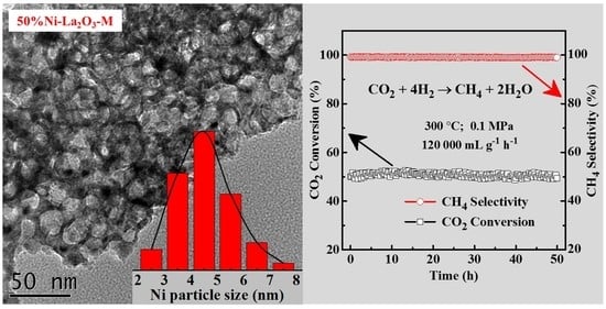
2.2. Catalytic Performance

The activity catalysts were tested in CO2 methanation at temperatures of 250–450 °C. CO2 conversion and CH4 selectivity are shown in Figure 5a,b, respectively. Compared with 50% Ni–La2O3, the catalyst of 50% Ni–La2O3–M exhibited higher CO2 conversion and CH4 selectivity, indicating the latter is much more active than the former. For 50% Ni–La2O3–M catalysts, the highest CO2 conversion of 76% was obtained at around 400 °C with a CH4 selectivity of around 99.5%. CO2 conversion of 50% Ni–La2O3–M decreased to 71% at 450 °C, which is limited by the thermodynamic equilibrium due to the CO2 methanation reaction being an exothermic reaction. In the meantime, CH4 selectivity decreased to 98%, which is caused by the accelerated generation of CO derived from the reverse water gas shift reaction. Similar variation trends in conversion and selectivity can also be observed for 50% Ni–La2O3 catalysts. Furthermore, it should be noted that the CO2 conversion of 50% Ni–La2O3–M reached 51% at 300 °C, while 50% Ni–La2O3 only reached 9%, suggesting that the 50% Ni–La2O3–M catalyst has good low-temperature activity. As listed in Table 3, the turnover frequency (TOF) of 50% Ni–La2O3–M at 250 °C is 12-fold higher than that of 50% Ni–La2O3, which indicates that the small Ni particles embedded by La2O3 in 50% Ni–La2O3–M were more active than the Ni particles supported on La2O3 in 50% Ni–La2O3. Combined with the characterization results, it is shown that the special mesoporous embedded structure in 50% Ni–La2O3–M led to an abundant metal–support interface, thus increasing the catalytic activity.
As shown in Figure 6, the stability test of 50% Ni–La2O3–M was carried out at a high gas hourly space velocity (GHSV) of 120,000 mL g−1 h−1, and the temperature was set to 300 °C. CO2 conversions of 50% Ni–La2O3–M catalyst maintained stable catalytic performance throughout 50 h of testing. CO2 conversion and CH4 selectivity remained around 51% and 98%, respectively. This indicates that the La2O3-supported Ni catalyst prepared by the colloidal solution combustion method has excellent stability.
The sintering and carbon deposition of Ni nanoparticles are the main reasons for the decline in catalyst performance during the stability test of CO2 methanation. The chosen 50% Ni–La2O3–M was characterized by XRD and TEM techniques. The absence of carbon nanotubes or nanofibers in TEM photographs (Figure 7) showed that no detectable carbon deposition occurred, meaning that no carbon was deposited on the surface of the catalysts. That is to say, 50% Ni–La2O3–M catalyst has good performance in resisting carbon deposits.
The XRD results in Figure 1 exhibited broad and weak diffraction peaks for Ni in used 50% Ni–La2O3–M catalysts, indicating that the small particle size of nickel allowed them to stay in this catalyst. Furthermore, the peaks of Ni in used 50% Ni–La2O3–M are similar to that of reduced 50% Ni–La2O3–M, indicating that the active component did not grow during the stability test. As given in Table 2, Ni crystal sizes as calculated from XRD patterns using Scherrer’s equation were 4.5 and 4.3 nm for the used and reduced 50% Ni–La2O3–M, respectively. In other words, the 50% Ni–La2O3–M catalyst had good resistance to sintering during the stability test. Similar phenomena can be verified in TEM results.
TEM and HR-TEM images of the used 50% Ni–La2O3–M are shown in Figure 7. The ordered mesoporous structure was well maintained and the lattice distance of 2.03 Å corresponds to the lattice parameters for Ni (111) [32]. Meanwhile, it can be observed that the Ni particle size of 50% Ni–La2O3–M was centered around 4.5 nm and that no sintering occurred during the stability test.
Summarizing Section 3.2, the catalyst of 50% Ni–La2O3–M performs well in terms of CO2 methanation activity, and the stability test demonstrated that it has superior activity and excellent selectivity. The XRD and TEM results demonstrate that 50% Ni–La2O3–M possessed an ordered mesoporous structure, and that the Ni particle size was small. Meanwhile, the TEM results demonstrate that the catalyst prepared by colloidal solution combustion shows good resistance to carbon deposition. Combining the characterization of 50% Ni–La2O3–M with its good performance results, we concluded that the improved activity and stability of 50% Ni–La2O3–M catalysts can be attributed to the small Ni particle size embedded by amorphous La2O3, which creates a large amount of interface between the Ni and the La2O3 support.

3. Materials and Methods

3.1. Synthesis of Catalysts

We used the colloidal solution combustion method to prepare 50% Ni–La2O3–M catalysts. During the combustion reaction, glycine (NH2NH2COOH) was used as fuel, and metal nitrates (nickel nitrate and lanthanum nitrate) were used as oxidant. Aqueous colloidal SiO2 LUDOX TMA (Sigma-Aldrich, Saint Louis, USA, 34 wt %, diameter of 22 nm) was used as a hard template to create pores. Typically, La(NO3)3·6H2O (1.33 g), Ni(NO3)2·6H2O (2.48 g), and glycine (0.60 g) were added to deionized water (6.30 mL). After stirring the solution for 10 min and ultrasonic dispersion for 20 min, colloidal SiO2 (1.26 mL) was added and subjected to ultrasound for 30 min. After this, the solution was transferred onto a hot plate and heated to 200 °C for pyrolysis, during which glycine and nitrate metal undergo a combustion reaction accompanied by the generation of metal oxides and gases. After glycine is fully burned and cooled to room temperature, the metal oxides were calcined at 600 °C for 4 h. The obtained powder was dispersed into a hot NaOH solution to etch the silica. Following this, the powder was washed three times with deionized water and three times with ethanol. After drying at 80 °C for 12 h, 50% Ni–La2O3–M catalyst was obtained, with the weight content of Ni being 50%.
For comparison, 50% Ni–La2O3 catalysts were prepared by the solution combustion method without adding colloidal SiO2. The prepared sample was referred to as 50% Ni–La2O3.

3.2. Characterization of Catalysts

N2 isotherms were carried out on an Autosorb-iQ analyzer (Quantachrome Instruments, Boynton Beach, FL, USA) at −196 °C. The catalysts were evaluated at 300 °C for 4 h before the measurements. The BET method was used to calculate the specific surface area. The pore size distributions were obtained from the absorption branch using quenched solid density functional theory (QSDFT). The total pore volumes were calculated according to the adsorption point at P/P0 = 0.994.
X-ray diffraction (XRD) patterns were obtained on a DX-2700 X-ray diffractometer (Haoyuan Instrument, Dandong, China) with Cu Kα radiation (λ = 0.15406 nm). H2-temperature programmed reduction (H2-TPR) was performed on a TP-5080 multifunctional adsorption apparatus (Xianquan, Tianjin, China). A detailed description of the H2-TPR experiment can be found in our previous publication [33]. H2-temperature programmed desorption (H2-TPD) was performed on the same apparatus as H2-TPR. The catalyst (100 mg), after reduction at 400 °C for 40 min in 5% H2/Ar, was cooled to room temperature in 5% H2/Ar. After being purged with pure Ar for 1 h, the catalyst was heated for H2 desorption from room temperature to 900 °C at a rate of 10 °C/min in pure Ar. Ni dispersion was calculated from the desorption of H2 using the assumption that the stoichiometric ratio of H/Nisurface is 1. Transmission electron microscope (TEM) images of the catalysts were taken by a Tecnai G2 F20 microscope (FEI Company, Hillsboro, OR, USA).

3.3. Catalytic Performance Test for CO2 Methanation

Catalytic tests were performed in a fixed-bed reactor (i.d. = 8 mm) at atmospheric pressure in the temperature range of 250–450 °C under a reactant gas flow of 100 mL/min (CO2/H2/Ar = 1:4:5). The catalyst sample (50 mg) was diluted with SiO2 (100 mg) and loaded into the reactor. Before the reaction, the catalyst was reduced at 400 °C in 20% H2/Ar (50 mL min−1) for 40 min. After reduction, the catalyst was cooled to 250 °C in 20% H2/Ar. Following this, the reactant gas flow was introduced into the reactor. At each reaction temperature point, the sampling and analysis of reacted gas were conducted after one hour. The stability tests were carried out at 300 °C. The product gas was analyzed using an online gas chromatograph (Techcomp GC-7900, Shanghai, China). CO2 conversion ( X CO 2 )) and selectivity of CH4 ( S CH 4 ) were calculated as follows:
X CO 2 = [ CO 2 ] in [ CO 2 ] out [ CO 2 ] in × 100 % ,
S CH 4 = [ CH 4 ] out [ CO ] out + [ CH 4 ] out × 100 % ,
where [CO2]in and [CO2]out are the inlet and outlet concentrations of CO2, respectively. [CH4]out is the outlet concentration of CH4.
The turnover frequency (TOF) value, representing the number of converted CO2 molecules per Ni atom per second, was calculated from the CO2 conversion and Ni dispersion [34].

Author Contributions

Conceptualization: D.G. and L.W.; Data curation: G.T., D.G. and L.W.; Formal analysis: G.T., H.L. and L.W.; Funding acquisition: H.L. and L.W.; Investigation: G.T., H.L. and L.W.; Writing—original draft: G.G.; Writing—review & editing: H.L. and L.W.

Funding

This research was funded by the Natural Science Foundation of China (No. 21406206), the university students’ innovation program of Zhejiang province (No. 2017R411017) and the national university students’ innovation and entrepreneurship training program (No. 201710340016).

Acknowledgments

The authors would like to thank Jiliang Yang and Yundi Zhang for help with the experiments and measurements.

Conflicts of Interest

The authors declare no conflict of interest.

References

  1. Ma, J.; Sun, N.; Zhang, X.; Zhao, N.; Xiao, F.; Wei, W.; Sun, Y. A short review of catalysis for CO2 conversion. Catal. Today 2009, 148, 221–231. [Google Scholar] [CrossRef]
  2. Wang, Y.; Tan, L.; Tan, M.; Zhang, P.; Fang, Y.; Yoneyama, Y.; Yang, G.; Tsubaki, N. Rationally Designing Bifunctional Catalysts as an Efficient Strategy To Boost CO2 Hydrogenation Producing Value-Added Aromatics. ACS Catal. 2019, 9, 895–901. [Google Scholar] [CrossRef]
  3. Su, X.; Xu, J.; Liang, B.; Duan, H.; Hou, B.; Huang, Y. Catalytic carbon dioxide hydrogenation to methane: A review of recent studies. J. Energy Chem. 2016, 25, 553–565. [Google Scholar] [CrossRef]
  4. Rönsch, S.; Schneider, J.; Matthischke, S.; Schlüter, M.; Götz, M.; Lefebvre, J.; Prabhakaran, P.; Bajohr, S. Review on methanation—From fundamentals to current projects. Fuel 2016, 166, 276–296. [Google Scholar] [CrossRef]
  5. Karelovic, A.; Ruiz, P. Mechanistic study of low temperature CO2 methanation over Rh/TiO2 catalysts. J. Catal. 2013, 301, 141–153. [Google Scholar] [CrossRef]
  6. Swalus, C.; Jacquemin, M.; Poleunis, C.; Bertrand, P.; Ruiz, P. CO2 methanation on Rh/γ-Al2O3 catalyst at low temperature: “In situ” supply of hydrogen by Ni/activated carbon catalyst. Appl. Catal. B 2012, 125, 41–50. [Google Scholar] [CrossRef]
  7. Sharma, S.; Hu, Z.; Zhang, P.; McFarland, E.W.; Metiu, H. CO2 methanation on Ru-doped ceria. J. Catal. 2011, 278, 297–309. [Google Scholar] [CrossRef]
  8. Kim, H.Y.; Lee, H.M.; Park, J.-N. Bifunctional Mechanism of CO2 Methanation on Pd-MgO/SiO2 Catalyst: Independent Roles of MgO and Pd on CO2 Methanation. J. Phys. Chem. C 2010, 114, 7128–7131. [Google Scholar] [CrossRef]
  9. Razzaq, R.; Li, C.; Usman, M.; Suzuki, K.; Zhang, S. A highly active and stable Co4N/γ-Al2O3 catalyst for CO and CO2 methanation to produce synthetic natural gas (SNG). Chem. Eng. J. 2015, 262, 1090–1098. [Google Scholar] [CrossRef]
  10. Schubert, M.; Pokhrel, S.; Thomé, A.; Zielasek, V.; Gesing, T.M.; Roessner, F.; Mädler, L.; Bäumer, M. Highly active Co–Al2O3-based catalysts for CO2 methanation with very low platinum promotion prepared by double flame spray pyrolysis. Catal. Sci. Technol. 2016, 6, 7449–7460. [Google Scholar] [CrossRef]
  11. Liu, H.; Xu, S.; Zhou, G.; Huang, G.; Huang, S.; Xiong, K. CO2 hydrogenation to methane over Co/KIT-6 catalyst: Effect of reduction temperature. Chem. Eng. J. 2018, 351, 65–73. [Google Scholar] [CrossRef]
  12. Bian, Z.; Chan, Y.M.; Yu, Y.; Kawi, S. Morphology dependence of catalytic properties of Ni/CeO2 for CO2 methanation: A kinetic and mechanism study. Catal. Today 2018. [Google Scholar] [CrossRef]
  13. Le, T.A.; Kim, T.W.; Lee, S.H.; Park, E.D. Effects of Na content in Na/Ni/SiO2 and Na/Ni/CeO2 catalysts for CO and CO2 methanation. Catal. Today 2018, 303, 159–167. [Google Scholar] [CrossRef]
  14. Le, T.A.; Kim, M.S.; Lee, S.H.; Kim, T.W.; Park, E.D. CO and CO2 methanation over supported Ni catalysts. Catal. Today 2017, 293–294, 89–96. [Google Scholar] [CrossRef]
  15. Stangeland, K.; Kalai, D.; Li, H.; Yu, Z. CO2 Methanation: The Effect of Catalysts and Reaction Conditions. Energy Procedia 2017, 105, 2022–2027. [Google Scholar] [CrossRef]
  16. Liu, Q.; Tian, Y. One-pot synthesis of NiO/SBA-15 monolith catalyst with a three-dimensional framework for CO2 methanation. Int. J. Hydrog. Energy 2017, 42, 12295–12300. [Google Scholar] [CrossRef]
  17. Chen, C.-S.; Budi, C.S.; Wu, H.-C.; Saikia, D.; Kao, H.-M. Size-Tunable Ni Nanoparticles Supported on Surface-Modified, Cage-Type Mesoporous Silica as Highly Active Catalysts for CO2 Hydrogenation. ACS Catal. 2017, 7, 8367–8381. [Google Scholar] [CrossRef]
  18. Bacariza, M.C.; Graça, I.; Bebiano, S.S.; Lopes, J.M.; Henriques, C. Micro- and mesoporous supports for CO2 methanation catalysts: A comparison between SBA-15, MCM-41 and USY zeolite. Chem. Eng. Sci. 2018, 175, 72–83. [Google Scholar] [CrossRef]
  19. Sun, X.; Suarez, A.I.O.; Meijerink, M.; van Deelen, T.; Ould-Chikh, S.; Zečević, J.; de Jong, K.P.; Kapteijn, F.; Gascon, J. Manufacture of highly loaded silica-supported cobalt Fischer–Tropsch catalysts from a metal organic framework. Nat. Commun. 2017, 8, 1680. [Google Scholar] [CrossRef]
  20. Garbarino, G.; Wang, C.; Cavattoni, T.; Finocchio, E.; Riani, P.; Flytzani-Stephanopoulos, M.; Busca, G. A study of Ni/La-Al2O3 catalysts: A competitive system for CO2 methanation. Appl. Catal. B 2019, 248, 286–297. [Google Scholar] [CrossRef]
  21. Song, H.; Yang, J.; Zhao, J.; Chou, L. Methanation of Carbon Dioxide over a Highly Dispersed Ni/La2O3 Catalyst. Chin. J. Catal. 2010, 31, 21–23. [Google Scholar] [CrossRef]
  22. Li, X.; Li, D.; Tian, H.; Zeng, L.; Zhao, Z.-J.; Gong, J. Dry reforming of methane over Ni/La2O3 nanorod catalysts with stabilized Ni nanoparticles. Appl. Catal. B 2017, 202, 683–694. [Google Scholar] [CrossRef]
  23. Voskanyan, A.A.; Chan, K.-Y.; Li, C.-Y.V. Colloidal Solution Combustion Synthesis: Toward Mass Production of a Crystalline Uniform Mesoporous CeO2 Catalyst with Tunable Porosity. Chem. Mater. 2016, 28, 2768–2775. [Google Scholar] [CrossRef]
  24. Wang, L.; Liu, H. Mesoporous Co-CeO2 catalyst prepared by colloidal solution combustion method for reverse water-gas shift reaction. Catal. Today 2018, 316, 155–161. [Google Scholar] [CrossRef]
  25. Leofanti, G.; Padovan, M.; Tozzola, G.; Venturelli, B. Surface area and pore texture of catalysts. Catal. Today 1998, 41, 207–219. [Google Scholar] [CrossRef]
  26. Neimark, A.V.; Lin, Y.; Ravikovitch, P.I.; Thommes, M. Quenched solid density functional theory and pore size analysis of micro-mesoporous carbons. Carbon 2009, 47, 1617–1628. [Google Scholar] [CrossRef]
  27. Tada, S.; Shimizu, T.; Kameyama, H.; Haneda, T.; Kikuchi, R. Ni/CeO2 catalysts with high CO2 methanation activity and high CH4 selectivity at low temperatures. Int. J. Hydrog. Energy 2012, 37, 5527–5531. [Google Scholar] [CrossRef]
  28. Pereñíguez, R.; González-DelaCruz, V.M.; Holgado, J.P.; Caballero, A. Synthesis and characterization of a LaNiO3 perovskite as precursor for methane reforming reactions catalysts. Appl. Catal. B 2010, 93, 346–353. [Google Scholar] [CrossRef]
  29. Zou, Y.; Wang, Y. NiO nanosheets grown on graphene nanosheets as superior anode materials for Li-ion batteries. Nanoscale 2011, 3, 2615–2620. [Google Scholar] [CrossRef] [PubMed]
  30. Li, S.; Tang, H.; Gong, D.; Ma, Z.; Liu, Y. Loading Ni/La2O3 on SiO2 for CO methanation from syngas. Catal. Today 2017, 297, 298–307. [Google Scholar] [CrossRef]
  31. Xue, Y.; Yan, C.; Zhao, X.; Huang, S.; Guo, C. Ni/La2O3-ZrO2 catalyst for hydrogen production from steam reforming of acetic acid as a model compound of bio-oil. Korean J. Chem. Eng. 2017, 34, 305–313. [Google Scholar] [CrossRef]
  32. Nuvula, S.; Sagar, T.V.; Valluri, D.K.; Sai Prasad, P.S. Selective substitution of Ni by Ti in LaNiO3 perovskites: A parameter governing the oxy-carbon dioxide reforming of methane. Int. J. Hydrog. Energy 2018, 43, 4136–4142. [Google Scholar] [CrossRef]
  33. Wang, L.; Liu, H.; Ye, H.; Hu, R.; Yang, S.; Tang, G.; Li, K.; Yang, Y. Vacuum Thermal Treated Ni-CeO2/SBA-15 Catalyst for CO2 Methanation. Nanomaterials 2018, 8, 759. [Google Scholar] [CrossRef] [PubMed]
  34. Li, S.; Guo, S.; Gong, D.; Kang, N.; Fang, K.-G.; Liu, Y. Nano composite composed of MoOx-La2O3-Ni on SiO2 for storing hydrogen into CH4 via CO2 methanation. Int. J. Hydrog. Energy 2019, 44, 1597–1609. [Google Scholar] [CrossRef]
Figure 1. Nitrogen adsorption–desorption isotherms curves (a) and pore size distributions (b) of 50% Ni–La2O3–M and 50% Ni–La2O3.
Catalysts 09 00442 g001
Figure 2. X-ray diffraction (XRD) patterns of 50% Ni–La2O3–M and 50% Ni–La2O3. Reduced catalysts were reduced at 400 °C for 40 min with 20% H2/Ar. We used 50% Ni–La2O3–M at 300 °C for 50 h in a CO2 methanation reaction.
Catalysts 09 00442 g002
Figure 3. TEM images and NiO particle size distributions of fresh catalysts: (ac,g) 50% Ni–La2O3–M and (df,h) 50% Ni–La2O3.
Catalysts 09 00442 g003
Figure 4. H2-temperature programmed reduction (H2-TPR) curves of 50% Ni–La2O3–M and 50% Ni–La2O3 catalysts.
Catalysts 09 00442 g004
Figure 5. (a) CO2 conversion and (b) CH4 selectivity over 50% Ni–La2O3–M and 50% Ni–La2O3 in CO2 methanation reaction at a gas hourly space velocity (GSHV) of 120,000 mL g−1 h−1 and 0.1 MPa in the gas mixture of H2/CO2/Ar = 4/1/5.
Catalysts 09 00442 g005
Figure 6. Stability of 50% Ni–La2O3–M in CO2 methanation reaction at GSHV = 120,000 mL g−1 h−1 on stream at 300 °C and 0.1 MPa in H2/CO2/Ar = 4/1/5.
Catalysts 09 00442 g006
Figure 7. TEM images of the catalysts after stability test: (a,b) 50% Ni–La2O3–M and (c,d) 50% Ni–La2O3.
Catalysts 09 00442 g007
Table 1. Physical properties of 50% Ni–La2O3–M and 50% Ni–La2O3.
SamplesSBET (m2 g−1)Pore Volume (cm3 g−1)Average pore size (nm)
Fresh 50% Ni–La2O37.20.1371
Fresh 50% Ni–La2O3–M70.40.3218
Reduced 50% Ni–La2O3–M a79.20.3719
Used 50% Ni–La2O3–M b55.50.4516
a The catalyst was reduced at 400 °C for 40 min in 20% H2/Ar. b The catalyst was used at 300 °C for 50 h under methanation reaction conditions.
Table 2. Crystallite particle size of Ni and NiO.
CatalystsCrystal Size of NiO (nm)Ni Crystal Size (nm) a
By XRD aBy TEM b
Fresh 50% Ni–La2O3–M3.03.2/
Reduced 50% Ni–La2O3–M//4.3
Used 50% Ni–La2O3–M//4.5
Fresh 50% Ni–La2O37.06.8/
Reduced 50% Ni–La2O3//7.1
a Calculated from XRD results based on Scherrer’s equation. b Average NiO particle size was estimated from TEM.
Table 3. Ni dispersion and turnover frequency (TOF) calculated from H2-TPD results.
CatalystsNi Dispersion (%) aTOF (× 10−3 s−1) b
50% Ni–La2O36.934.0
50% Ni–La2O3–M4.0157.0
a Calculated from H2-temperature programmed desorption (H2-TPD) results. b TOF (s−1) represents the number of CO2 molecules converted per Ni surface atom per second at 250 °C.

