Article

Effect of Mg/Al2O3 and Calcination Temperature on the Catalytic Decomposition of HFC-134a

1
Department of Environmental Sciences and Biotechnology, Hallym University, Chuncheon 24252, Korea
2
Department of Science and Humanities, Saveetha School of Engineering, Chennai 600124, India
3
Research Center for Climate Change and Energy, Hallym University, Chuncheon 24252, Korea
4
School of Environmental Engineering, University of Seoul, Seoul 02504, Korea
5
Department of Environmental Engineering, Daegu University, Gyeongsan 38453, Korea
*
Authors to whom correspondence should be addressed.
Catalysts 2019, 9(3), 270; https://doi.org/10.3390/catal9030270
Submission received: 3 February 2019 / Revised: 4 March 2019 / Accepted: 11 March 2019 / Published: 16 March 2019
(This article belongs to the Special Issue Synthesis and Application of Zeolite Catalysts)

Abstract

:
This paper evaluated the effect of calcination temperature and the use of Mg/Al2O3 on the decomposition of HFC-134a. Two commercialized catalysts, Al2O3 and Mg/Al2O3, were calcined at two different temperatures (500 and 650 °C) and their physicochemical characteristics were examined by X-ray diffraction, Brunauer–Emmett–Teller analysis, and the temperature-programed desorption of ammonia and carbon dioxide analysis. The results show that, in comparison to Al2O3, 5% Mg/Al2O3 exhibited a larger Brunauer–Emmett–Teller surface area and higher acidity. The relative amount of strong acid sites of the catalysts decreased with increasing calcination temperature. Although a more than 90% decomposition rate of HFC-134a was achieved over all catalysts during the sequential decomposition test of HFC-134a using a vertical plug flow reactor connected directly to a gas chromatography/mass spectrometry system, the lifetime of the catalyst differed according to the catalyst type. Compared to Al2O3, Mg/Al2O3 revealed a longer lifetime and less coke formation due to the increased Brunauer–Emmett–Teller surface area and weak Lewis acid sites and basic sites arising from Mg impregnation. Higher temperature calcination extended the catalyst lifetime with the formation of less coke due to the smaller number of strong acid sites, which can lead to severe coke formation. A valuable by-product, trifluoroethylene, was formed as a result of the decomposition. Based on the experimental results, a reaction is proposed which reasonably explains the decomposition reaction.

1. Introduction

Rapid global warming and climate change in recent decades and the increased frequency and impact of environmental disasters, such as global warming, sea level rises, heat, drought, and floods, have raised global interest in greenhouse gases [1,2]. Although greenhouse gases, such as CO2, CH4, N2O, and O3, are produced naturally, their concentrations have increased due to human activity [3]. Among the various kinds of greenhouse gases, fluorinated greenhouse gases are not only synthesized and emitted by human activity but also have a much higher global warming potential (GWP) than other greenhouse gases [4]. Therefore, many studies have focused on minimizing use, recycling, and direct destruction of these fluorinated greenhouse gases [5]. After the Montreal Protocol, the use of chlorofluorocarbons as refrigerants was banned and hydrofluorocarbons (HFCs) have since been used as substitutes [6]. Among the various kinds of HFCs, 1,1,1,2-tetrafluoroethane (HFC-134a) is the most widely used coolant for air conditioners, but its GWP value is also very high, 1300 times higher than CO2 [7]. The seriousness of HFC-134a was highlighted in the Kyoto Protocol [8] and a decision was made to reduce its usage in the Kigali Amendment to the Montreal Protocol [9].
Various technologies have been used to minimize HFC-134a emissions, including recycling after purification using polymeric membranes [10] and the direct destruction of waste HFC-134a. Although HFC-134a can be purified using membrane technologies, their technical and economical limitations are difficult to overcome due to the high cost [11] in achieving the target HFC purity required for reuse. Therefore, many studies have considered the direct destruction [12] of HFC-134a instead. The direct destruction of HFC-134a can be achieved by applying thermal conversion technologies, such as incineration, plasma, and pyrolysis. In the case of incineration, combustion in air and ancillary fuels has been introduced, but the additional fuel input cost and equipment corrosion due to excessive HF generation are recognized as problems [13]. Steam plasma is a technology that has high HFC-134a decomposition efficiency [14], but plant enlargement is difficult due to corrosion, probably caused by the high HF concentration in the product gas, and unstable plasma discharge due to the use of steam. The high cost of plasma plant construction and its operation limit its actual commercialization. Pyrolysis can be considered as a favorable process for the decomposition of HFC-134a, but an excessively high temperature (>750 °C) is required because of its high thermal stability [15]. Recently, many researchers have reported the catalytic pyrolysis of HFC-134a because of the lower decomposition temperatures. Ni/Al2O3 [16], waste concrete [15], and metal phosphate catalysts [17] have been used. Han et al. [18] compared the HFC-134a decomposition efficiencies of metal oxides, such as CaO and Al2O3. They reported the highest decomposition efficiency of HFC-134a over Al2O3, but the rapid deactivation of Al2O3 by its conversion to AlF3 limits its use.
Many studies have applied metal-impregnated Al2O3 to increase the overall lifetime of the catalyst for the decomposition of fluorinated hydrocarbons. Han et al. [19] reported that the decomposition tendency for trifluoromethane and the stability of the substrate could be increased by metal impregnation onto Al2O3. Song et al. [20] achieved a high level of CF4 hydrolytic decomposition over metal-supported Al2O3 and explained that the catalyst modified by metal impregnation can preserve the Lewis acid sites of the catalyst, which can act as a strong active site for the decomposition of CF4. Li et al. reported the use of a metal-supported catalyst for the catalytic decomposition of HFC-143a [21]. They explained that metal phosphates can provide a more stable decomposition efficiency of fluorinated hydrocarbons due to the presence of weak acidic sites and dehydrofluorination proceeds via a carbonium-ion mechanism. Previous studies on the use of metal-supported catalysts for the decomposition of other fluorinated hydrocarbons suggested that the catalytic efficiency of Al2O3 can be increased and become more stable by metal impregnation, but there has been little systematic research on its use for HFC-134a decomposition.
Therefore, this study examined the catalytic decomposition of HFC-134a over Mg-supported Al2O3 (Mg/Al2O3). Al2O3 (γ-phase) and Mg/Al2O3 (γ-phase) were used throughout the experimental investigation. The physicochemical properties (pore size, acidity, and structure) of Al2O3 and Mg/Al2O3, which was calcined at different temperatures (500 and 650 °C), were analyzed using Brunauer–Emmett–Teller (BET), ammonia–temperature programmed desorption (NH3-TPD), and carbon dioxide–temperature programmed desorption (CO2-TPD), and X-ray diffraction (XRD) measurements. The lifetime of each catalyst during the sequential decomposition of HFC-134a was estimated using vertical plug flow reactor–gas chromatography/mass spectrometry (VPFR-GC/MS).

2. Results

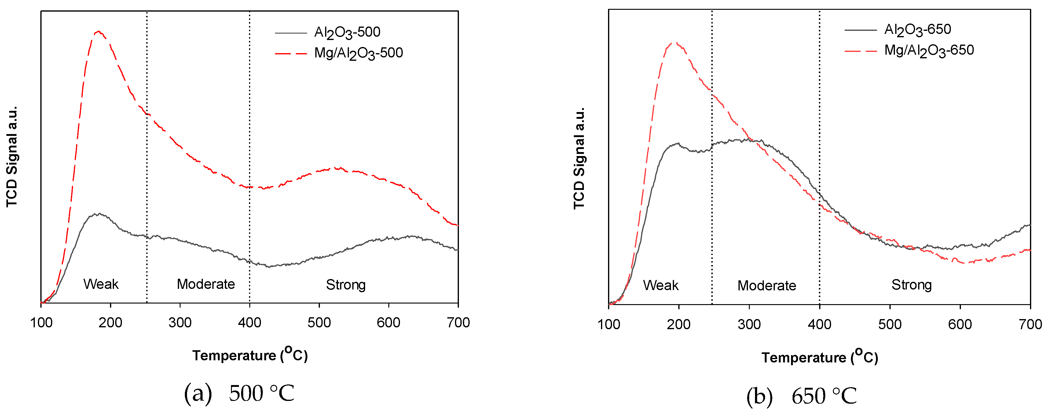
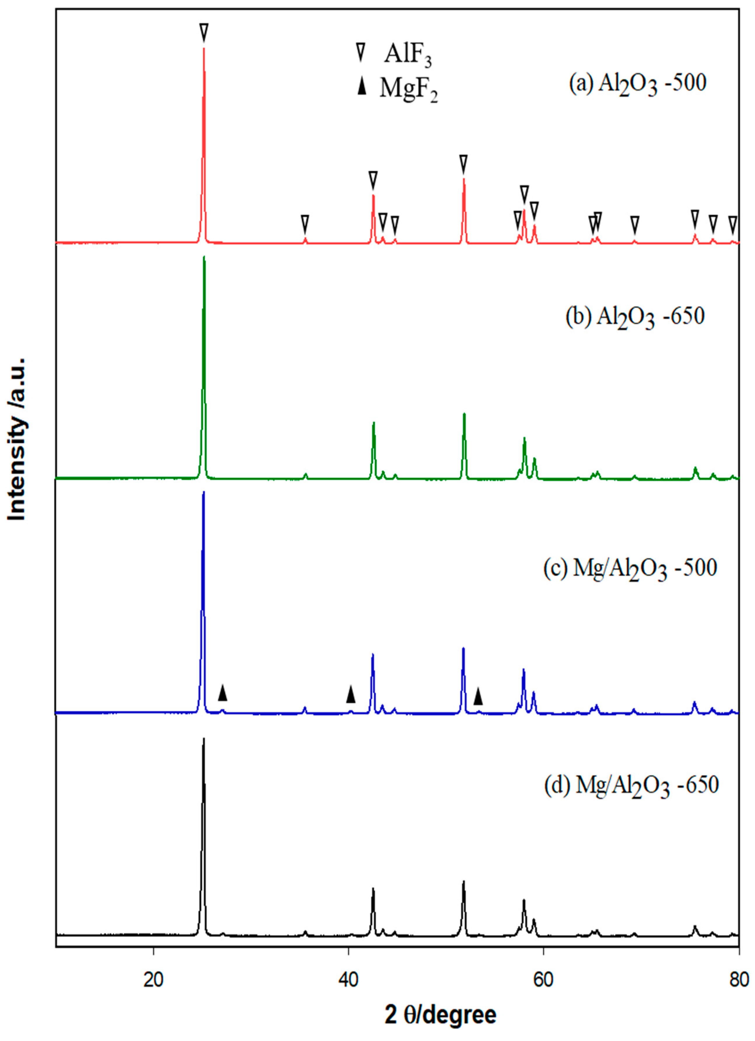
Physicochemical Properties of Catalysts
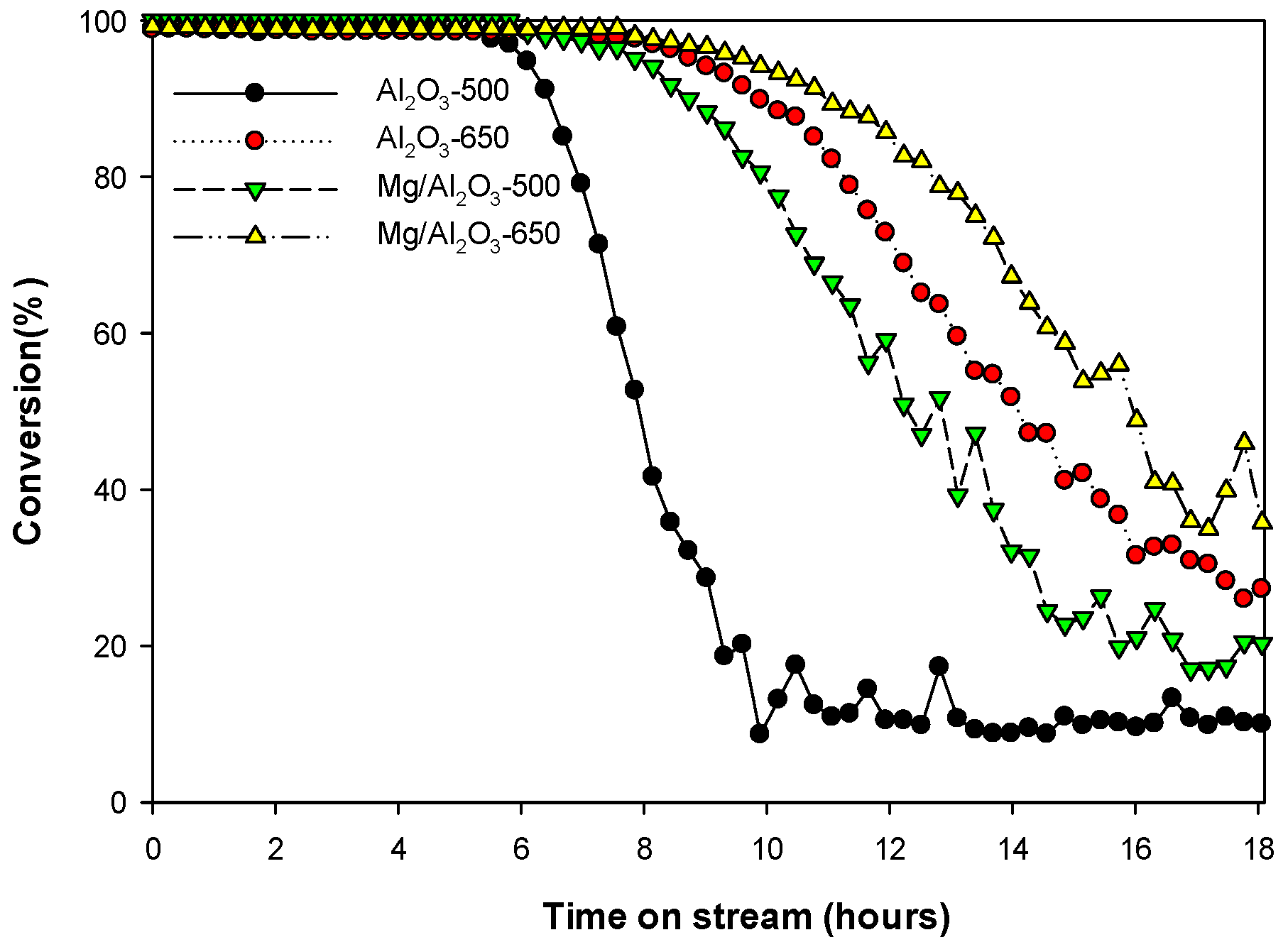
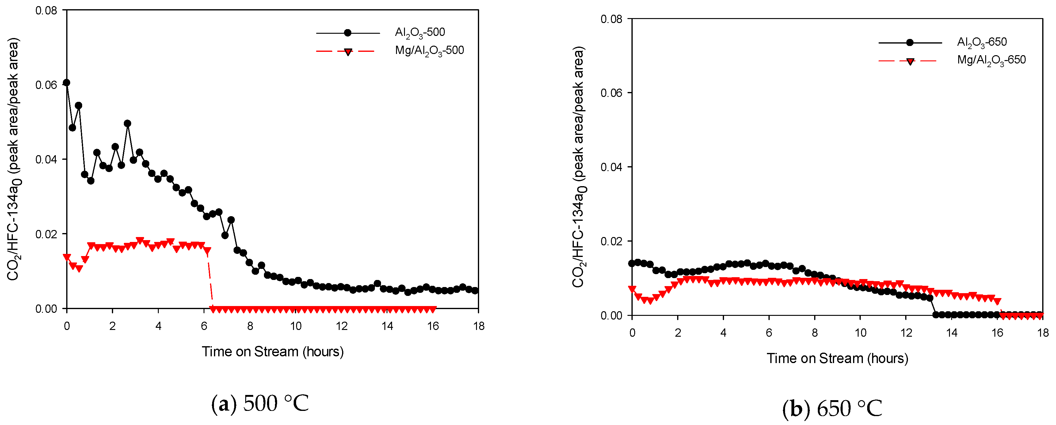
The BET surface areas of the Mg/Al2O3 catalysts (246 m2/g for Mg/Al2O3-500 and 227 m2/g for Mg/Al2O3-650) were larger than those of the Al2O3 catalysts (139 m2/g for Al2O3-500 and 140 m2/g for Al2O3-650). This suggests that the BET surface area of Al2O3 increased due to Mg impregnation. Figure 1 and Table 1 show the NH3-TPD curves and amounts of weak, moderate, and strong acid sites of Al2O3 and Mg/Al2 O3 catalysts, respectively. Mg/Al2O3-500 and Mg/Al2O3-650 had much higher weak acid amounts than Al2O3-500 and Al2O3-650, respectively. This suggests that the weak acidity of Al2O3 catalysts was increased by Mg impregnation. Jeon et al. [22,23] also reported that the addition of Mg increased weak Lewis acidity. Therefore, it can be concluded that weak Lewis acidity was increased with the addition of Mg to Al2O3.
In addition, both Al2O3-650 and Mg/Al2O3-650 revealed a smaller number of acid sites than Al2O3-500 and Mg/Al2O3-500, respectively. In particular, Al2O3-650 and Mg/Al2O3-650 had fewer strong acid sites than Al2O3-500 and Mg/Al2O3-500, respectively. This indicates that the calcination of Al2O3 and Mg/Al2O3 at higher temperatures (650 °C) can lead to a decrease in the number of strong acid sites [24]. The relative ratio of weak acidity/strong acidity was increased with Mg impregnation and the increase of calcination temperature.
The CO2-TPD curves of Al2O3 and Mg/Al2 O3 catalysts are shown in Figure S1 (Supplementary Information). Mg/Al2O3-500 and Mg/Al2O3-650 showed higher basicity than Al2O3-500 and Al2O3-650, suggesting that basicity increased by Mg impregnation. In addition, both Al2O3-650 and Mg/Al2O3-650 revealed a higher number of weak basic sites and a smaller number of strong basic sites than Al2O3-500 and Mg/Al2O3-500, respectively. The NH3- and CO2-TPD results suggest that calcination of Al2O3 and Mg/Al2O3 at higher temperatures (650 °C) can lead to an increase in the number of weak acidic and basic sites and a decrease in the number of strong acidic and basic sites. The well-balanced weak Lewis acidity and basicity may affect catalytic decomposition of HFC-134a.
Figure 2 shows XRD patterns of the Al2O3 and Mg/Al2O3 catalysts calcined at different temperatures. The XRD pattern of Al2O3 and Mg/Al2O3 catalysts had the characteristic broad peaks of Al2O3, representing the γ phase, at 46.6°, 67.1°, and 60.9° 2θ (JCPDS 29-63). On the other hand, the peaks could be differentiated by their intensities, as reported elsewhere [25]. The intensity of the line depends on the elemental composition; hence, the impregnation of magnesium onto alumina reduced the intensity of the peaks compared with those of the Al2O3 catalysts [26,27]. The typical XRD peaks of Mg particles were barely observed in the XRD pattern of Mg/Al2O3 catalysts. This suggests that Mg had penetrated into the substitutional sites of the Al lattice. Compared with the XRD peaks of Al2O3 catalysts, those of Mg/Al2O3 catalysts had broader peaks and their 2θ values were shifted to slightly lower values. Wagih [28] reported that the 2θ shift of the Al peak on the XRD pattern of Mg/Al2O3 occurs due to Mg atomic penetration into the Al matrix. Mg2+ ions with a larger ionic radius (86 pm) than Al3+ (67.5 pm) are believed to have entered the alumina lattice because the shift was slight and no secondary phases were observed. Other researchers [29] support these observations. An increase in the calcination temperature resulted in an increase in peak height [30], with magnesium-doped alumina calcined at 650 °C showing an intense peak compared with its equivalent calcined at 500 °C. This was attributed to a slight change in crystallinity that modified the surface morphology. Therefore, the larger BET surface area and higher number of weak acidic sites of Mg/Al2O3 than those of Al2O3 resulted from a structural change of Al2O3 caused by the atomic penetration of Mg into the substitutional sites of the Al lattice.

3. Discussion

Catalytic Decomposition of HFC-134a

Figure 3 depicts the conversion rates of HFC-134a obtained from the catalytic decomposition over Al2O3 and Mg/Al2O3 catalysts at 600 °C. Although HFC-134a was not decomposed by noncatalytic decomposition, the initial decomposition rates of HFC-134a over both catalysts were higher than 99.0%. Iizuka et al. [15] also indicated that temperatures higher than 750 °C, which are required for the noncatalytic decomposition of HFC-134a, could be decreased using an Al2O3 catalyst. The high decomposition rates of HFC-134a (>99%) were maintained for more than 6 h over all catalysts used in this study, but they decreased depending on the catalyst.
Mg/Al2O3 decomposed HFC-134a for a longer time than Al2O3. This suggests that the Mg impregnated on the surface of Al2O3 might play a crucial role in the decomposition reaction of HFC-134a. The larger BET surface area, higher amount of weak Lewis acid sites, and higher amount of weak basicity of Mg/Al2O3 catalysts than Al2O3 catalysts can also increase the catalyst lifetime for the decomposition of HFC-134a. These findings are in accordance with other studies reporting that a larger surface area allows better mass transfer, which facilitates a better opportunity for the catalyst to contact with the fluorinated gases [31,32].
In addition, the catalysts calcined at 650 °C, Al2O3-650 and Mg/Al2O3-650, also showed a longer lifetime than Al2O3-500 and Mg/Al2O3-500 in terms of the catalytic decomposition of HFC-134a. The BET surface areas of Al2O3-650 and Mg/Al2O3-650 were similar, respectively, to those of Al2O3-500 and Mg/Al2O3-500. In addition, the total acidity of Al2O3 and Mg/Al2O3 decreased with the increasing catalyst calcination temperature. The decrease in the number of strong acid sites on the catalysts calcined at 650 °C was the main factor increasing the lifetime of Al2O3 and Mg/Al2O3. Jia et al. [33] reported that the strong acid sites of Al2O3 led to higher coke formation, which can decrease the catalyst lifetime. Especially, the catalytic activities were well correlated with the ratio of weak acidic sites/strong acidic sites (Table 1). The increase of weak basic sites and a decrease of strong basic sites on the catalysts calcined at 650 °C can also be an important factor in increasing the lifetime of Al2O3 and Mg/Al2O3.
Figure 4 shows the rate of trifluoroethylene (TrFE, C2HF3) formation through the catalytic decomposition of HFC-134a over the Al2O3 and Mg/Al2O3 catalysts calcined at different temperatures. Compared with the Al2O3 catalysts, Mg/Al2O3 catalysts produced a larger amount of TrFE for a longer duration. In addition, the catalysts calcined at 650 °C produced a larger amount of TrFE than those calcined at 500 °C. This suggests that Mg impregnation and calcination at 650 °C can increase the catalyst lifetime not only for the decomposition of HFC-134a but also for the formation of TrFE. The efficient formation of TrFE is desirable because it is a significant feedstock for the synthesis of fluoroplastics and fluororubbers [16,33]. TrFE can be generated through hydrolysis of trichlorotrifluoroethane, but this is a difficult and an expensive process [34,35,36,37]. Therefore, efficient TrFE formation via the catalytic decomposition of HFC-134a over Mg/Al2O3 is meaningful because of its cost effectiveness.
Figure 5 shows the oxidative TG and DTG curves of deactivated catalysts collected after the sequential decomposition of HFC-134a. The catalytic decomposition of HFC-134a over Mg/Al2O3-650 formed the smallest amount of coke (3.7% ± 1%) followed in order by Mg/Al2O3-500 (3.9% ± 1%), Al2O3-650 (11.9% ± 1%), and Al2O3-500 (16.0% ± 1%), which is in the order of the HFC-134a decomposition efficiency of these catalysts. This suggests that the decomposition efficiency and catalyst lifetime are also strongly related to the amount of coke formed during the catalytic decomposition of HFC-134a. The Mg/Al2O3 catalysts produced a smaller amount of coke and the oxidation temperatures of the coke deposited on the Mg/Al2O3 catalysts were also lower than those deposited on Al2O3 catalysts. This means that the use of Mg/Al2O3 catalysts can provide higher decomposition efficiency for a longer duration than Al2O3 catalysts because of the small amount of coke deposition having a lower oxidation temperature.
Figure 6 shows the XRD pattern of the used Al2O3 and Mg/Al2O3 catalysts, which were collected from the furnace after the sequential catalytic decomposition of HFC-134a. The typical peak patterns of fresh Al2O3 catalysts were not observed in the XRD patterns of the spent catalysts, but the used Al2O3 catalysts revealed the typical XRD peak patterns of AlF3 (at 25°, 42°, 52°, and 58° 2θ [18]). This suggests that the Al2O3 catalysts were converted to AlF3 during the catalytic decomposition of HFC-134a over the Al2O3 catalysts. Based on the product distribution and the presence of AlF3, the decomposition mechanism of HFC-134a can be expressed using Equation (1) as follows:
Catalysts 09 00270 i001
When Mg/Al2O3 catalysts were used, the typical peaks of MgF2 were also observed on the XRD pattern of the used Mg/Al2O3 catalysts (at 24°, 42°, and 52° 2θ [16]), as shown in Figure 7c,d. This suggests that Mg was also directly involved in the defluorination reaction of HFC-134a according to the following reaction:
Catalysts 09 00270 i002
Figure 7 depicts the rate of CO2 formation during the catalytic decomposition of HFC-134a over Al2O3 and Mg/Al2O3 catalysts. The Mg/Al2O3 catalysts produced a higher rate of TrFE formation than the Al2O3 catalysts and a smaller level of CO2 production during the reaction. In addition, the Mg/Al2O3 catalysts produced a smaller amount of coke than the Al2O3 catalysts. This can explain the increased number of weak Lewis acidic sites by Mg impregnation to Al2O3 catalysts, which can increase the relative ratio (Table 1) of weak acid sites compared to strong acidic sites that result in severe coke formation. The decreased coke formation over Mg/Al2O3-650 compared with Mg/Al2O3-500 confirmed that the relative number of strong acid sites is strongly related to catalyst deactivation during the catalytic decomposition of HFC-134a.

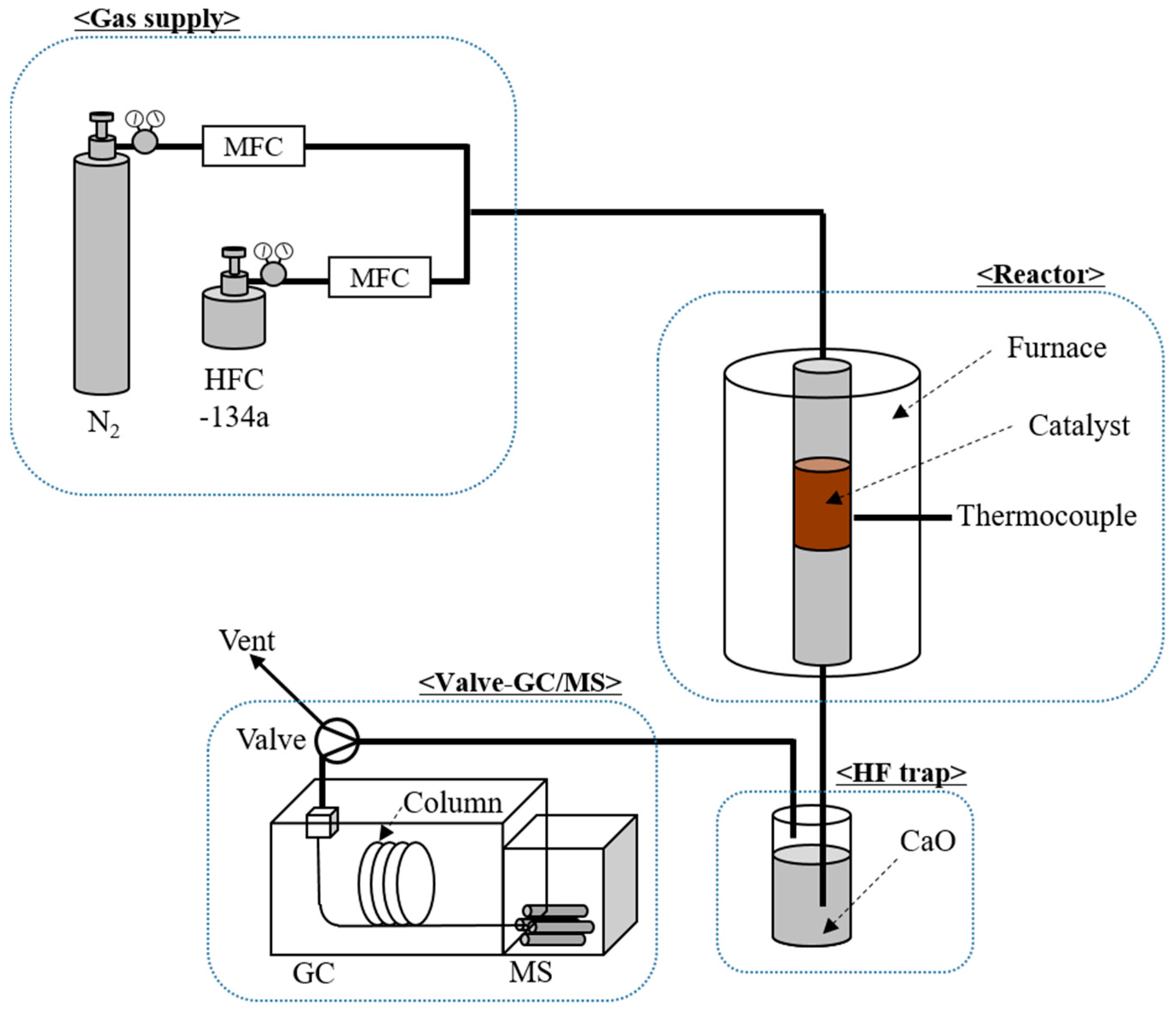
4. Materials and Methods

4.1. HFC-134a and Catalysts

Commercial HFC-134a was procured from RIGAS Co. Ltd., Daejeon, Republic of Korea, a gas manufacturer. Commercial Al2O3 and 5 wt % Mg/Al2O3 were obtained from Sasol. The catalysts were crushed and sieved to make small particles with a particle size between 1.0 and 1.7 mm. Prior to the catalytic experiments, all catalysts were calcined at different temperatures—500 and 650 °C—for 2 h and categorized as Al2O3-500, Al2O3-650, Mg/Al2O3-500, and Mg/Al2O3-650, respectively. The BET surface area and pore volume of each catalyst were measured using a BET analyzer (Micromeritics 3Flex). NH3-TPD analysis and XRD of the catalysts were performed using the same procedure reported elsewhere [38,39].

4.2. HFC-134a Decomposition Test

The efficiency of the catalysts on the catalytic decomposition of HFC-134a was examined by VPFR-GC/MS, as shown in Figure 8. The VPFR-GC/MS system consisted of a gas supply, reactor, HF trap, and valve-GC/MS. For the catalytic decomposition of HFC-134a, 1.2 g of catalyst was taken in the catalyst bed, and 98 mL/min of N2 gas and 2 mL/min of HFC-134a gas (2% of HFC-134a/N2) was supplied to the system. After the stabilization of the system, a temperature of 600 °C was set and the catalytic decomposition began. The gas hourly space velocity (GHSV) and weight hourly space velocity (WHSV) of the system were 1667 h1 and 5000 mL gcat1 h1, respectively. The product gases emitted from the reactor were transferred to a valve GC/MS system (7890A/5975C inert, Agilent, Santa Clara, USA) via an HF trap containing CaO. Table 2 lists the detailed GC/MS conditions used in this study. The peaks on the GC/MS chromatogram were identified by comparing the mass spectrum of each peak on the chromatogram using an MS library (NIST 08th). The MS peak areas for all the components on the chromatogram were integrated to determine their relative amounts. The conversion rate (%) of HFC-134a was calculated using Equation (3):
Conversion rate (%) = (1 − Aout/Ain) × 100
where Ain is the peak area of HFC-134a in the reactant gas, and Aout is the peak area of HFC-134a in the product gas.

5. Conclusions

The catalytic decomposition and conversion of HFC-134a was successfully carried out using Al2O3 and Mg/Al2O3 at 600 °C by calcinating the catalysts at 500 and 650 °C. The use of Mg/Al2O3 and an increase in calcination temperature led to a higher HFC-134a decomposition efficiency. Compared with Al2O3, Mg/Al2O3 had a larger BET surface area and higher weak Lewis acidity and basicity. The relative number of strong acidic sites in Al2O3 and Mg/Al2O3 also decreased with increasing calcination temperature from 500 to 650 °C, which led to a decrease in the amount of coke formation and increased the lifetime of the catalyst. TrFE, known for being valuable, was obtained as a by-product and its yield was higher over Mg/Al2O3.

Supplementary Materials

The following are available online at https://www.mdpi.com/2073-4344/9/3/270/s1, Figure S1: Carbon dioxide–-temperature programmed desorption (CO2-TPD) curves of Al2O3 and Mg/Al2O3 calcined at different temperatures—500 and 650 °C.

Author Contributions

Conceptualization, C.M.A.S., S.J., Y.-K.P., Y.-M.K., and S.K.; Funding acquisition, S.K.; Investigation, M.S. and A.A.; Supervision, S.J. and S.K.; Writing – original draft, C.M.A.S.; Writing – review & editing, Y.-K.P., Y.-M.K., and S.K.

Funding

This research was supported by Hallym University Research Fund (HRF-201809-007).

Conflicts of Interest

The authors declare no conflict of interest.

References

  1. GISTEMP Team. GISS Surface Temperature Analysis (GISTEMP), NASA Goddard Institute for Space Studies. Available online: https://data.giss.nasa.gov/gistemp/ (accessed on 2 November 2018).
  2. Hansen, J.; Ruedy, R.; Sato, M.; Lo, K. Global surface temperature change. Rev. Geophys. 2010, 48, 1–29. [Google Scholar] [CrossRef]
  3. Srinivasan, J. Climate Change Greenhouse gases and Aerosols. Resonance 2008, 13, 1146–1155. [Google Scholar] [CrossRef]
  4. Solomon, S.; Qin, D.; Manning, M.; Chen, Z.; Marquis, M.; Averyt, K.B.; Tignor, M.; Miller, H.L. (Eds.) IPCC Climate Change 2007: The Physical Science Basis. Contribution of Working Group I to the Fourth Assessment Report of the Intergovernmental Panel on Climate Change; Cambridge University Press: Cambridge, UK, 2007; p. 996. [Google Scholar]
  5. Richter, R.D.; Ming, T.; Davies, P.; Liu, W.; Caillol, S. Removal of non-CO2 greenhouse gases by large-scale atmospheric solar photocatalysis. Prog. Energy Combust. Sci. 2017, 60, 68–96. [Google Scholar] [CrossRef]
  6. Montreal Protocol- Achievements to Date and Challenges Ahead. Available online: http://ozone.unep.org/en/focus/montreal-protocol-achievements-date-and-challenges-ahead (accessed on 2 November 2018).
  7. Franklin, J. The atmospheric degradation and impact of 1,1,1,2-tetrafluoroethane (Hydrofluorocarbon 134a). Chemisphere 1993, 27, 1565–1601. [Google Scholar] [CrossRef]
  8. UNFCCC 1998. The Kyoto Protocol to the United Nations Framework Convention on Climate Change. Available online: https://unfccc.int/resource/docs/convkp/kpeng.pdf (accessed on 2 November 2018).
  9. Kigali Amendment to the Montreal Protocol. Available online: https://eia-international.org/wp-content/uploads/EIA-Kigali-Ammendment-to-the-Montreal-Protocol-FINAL.pdf (accessed on 2 November 2018).
  10. Shiojiri, K.; Yanagisawa, Y.; Yamasaki, A.; Kiyono, F. Separation of F-gases (HFC-134a and SF6) from gaseous mixtures with nitrogen by surface diffusion through a porous Vycor glass membrane. J. Membr. Sci. 2006, 282, 442–449. [Google Scholar] [CrossRef]
  11. Sanders, D.F.; Smith, Z.P.; Guo, R.; Robeson, L.M.; McGrath, J.E.; Paul, D.R.; Freeman, B.D. Energy-efficient polymeric gas separation membranes for a sustainable future: A review. Polymer 2013, 54, 4729–4761. [Google Scholar] [CrossRef] [Green Version]
  12. Mie, T.; Han, J.; He, X.; Qin, L. Investigation of HFC-13a Decomposition by combustion and its kinetic characteristics in a laboratory scale reactor. Environ. Prot. Eng. 2015, 41, 43–150. [Google Scholar]
  13. Ohm, T.I.; Chae, J.S.; Moon, S.H. Numerical and Experimental Study on the Destruction of Waste Refrigerant (HFCs) in Incinerator. J. Korea Soc. Waste Manag. 2016, 33, 454–460. [Google Scholar] [CrossRef]
  14. Watanabe, T.; Tsuru, T. Water plasma generation under atmospheric pressure for HFC destruction. Thin Solid Films 2008, 516, 4391–4396. [Google Scholar] [CrossRef]
  15. Iizuka, A.; Ishizaki, H.; Mizukoshi, A.; Noguchi, M.; Yamasaki, A.; Yanagisawa, Y. Simultaneous Decomposition and Fixation of F-Gases Using Waste Concrete. Ind. Eng. Chem. Res. 2011, 50, 11808–11814. [Google Scholar] [CrossRef]
  16. Jia, W.; Liu, M.; Lang, X.; Hu, C.; Li, J.; Zhu, Z. Catalytic dehydrofluorination of 1,1,1,2-tetrafluoroethane to synthesize trifluoroethylene over a modified NiO/Al2O3 catalyst. Catal. Sci. Technol. 2015, 5, 3103–3107. [Google Scholar] [CrossRef]
  17. Takita, Y.; Tanabe, T.; Ito, M.; Ogura, M.; Muraya, T.; Yasuda, S.; Nishiguchi, H.; Ishihara, T. Decomposition of CH2FCF3 (134a) over Metal Phosphate Catalysts. Ind. Eng. Chem. Res. 2002, 41, 2585–2590. [Google Scholar] [CrossRef]
  18. Han, T.U.; Yoo, B.S.; Kim, Y.M.; Hwang, B.A.; Sudibya, G.L.; Park, Y.K.; Kim, S. Catalytic conversion of 1,1,1,2-tetrafluoroethane (HFC-134a). Korean J. Chem. Eng. 2018, 35, 1611–1619. [Google Scholar] [CrossRef]
  19. Han, W.; Chen, Y.; Jin, B.; Liu, H.; Yu, H. Catalytic hydrolysis of trifluoroethane over alumina. Greenh. Gases 2014, 4, 121–130. [Google Scholar] [CrossRef]
  20. Song, J.Y.; Chung, S.H.; Kim, M.S.; Seo, M.G.; Lee, Y.H.; Lee, K.Y.; Kim, J.S. The catalytic decomposition of CF4 over Ce/Al2O3 modified by cerium sulphate precursor. J. Mol. Catal. 2013, 370, 50–55. [Google Scholar] [CrossRef]
  21. Li, G.L.; Nashiguchi, H.; Ishihara, T.; Moro-oka, Y.; Takita, Y. Catalytic dehydrofluorination of CF3CH3(HFC143a) into CF2CH2(HFC1132a). Appl. Catal. 1998, 16, 309–317. [Google Scholar] [CrossRef]
  22. Iung, E.; Jeon, S.; Kim, C.U.; Jeong, S.Y.; Park, Y.K.; Jeon, J.K. Hydro-upgrding of n-octadecane over Pt-Mg/HY catalysts. Catal. Today 2016, 265, 124–130. [Google Scholar]
  23. Jeon, S.H.; You, Y.; Jin, H.; Kim, C.U.; Park, Y.K.; Lee, C.H.; Jeon, J.K. Hydroupgrading of bio-oil over PtMg/KIT-6 catalysts. J. Nanosci. Nanotechnol. 2019, 19, 1126–1129. [Google Scholar] [CrossRef]
  24. Lu, J.; Zhao, Z.; Xu, C.; Duan, A.; Zhang, P. Effects of Calcination Temperature on the Acidity and Catalytic Performances of HZSM-5 Zeolite Catalysts for the Catalytic Cracking of n-Butane. J. Nat. Gas Chem. 2005, 14, 213–220. [Google Scholar]
  25. Tribalis, A.; Panagiotou, G.D.; Bourikas, K.; Sygellou, L.; Kennou, S.; Ladas, S.; Lycourghiotis, A.; Kordulis, C. Ni Catalysts supported on Modified Alumina for Diesel Steam Reforming. Catalysts 2016, 6, 11. [Google Scholar] [CrossRef]
  26. Novakovic, T.B.; Rozic, L.S.; Petrovic, S.P.; Vukovic, Z.M.; Mitric, M.N. Study of the effect of Mg(II) addition and annealing conditions on the structure of mesoporous aluminum oxide using Plackett-Burman design. J. Serb. Chem. Soc. 2015, 80, 1–14. [Google Scholar] [CrossRef]
  27. Nakrela, A.; Benramdane, N.; Bouzidi, A.; Kebbab, Z.; Medles, M.; Mathieu, C. Site location of Al-dopant in ZnO lattice by exploiting the structural and optical characterization of ZnO:Al thin films. Results Phys. 2016, 6, 133–138. [Google Scholar] [CrossRef]
  28. Wagih, A. Effect of Mg addition on mechanical and thermoelectrical properties of Al-Al2O3 nanocomposite. Trans. Nonferrous Met. Soc. China 2016, 26, 2810–2817. [Google Scholar] [CrossRef]
  29. Souza, J.J.N.; Meireles, B.R.L.A.; Cordeiro, A.M.T.M.; Santos, I.M.G.; Maria, A.S. Iron-doped Alfa-Alumina applied in the degradation of phenol solutions. Rev. Virtual Quim. 2017, 9, 2539–2550. [Google Scholar] [CrossRef]
  30. Matori, K.A.; Wah, L.C.; Hashim, M.; Ismail, I.; Mohd Zaid, M.H. Phase transformations of α-Alumina made from waste Aluminium via a precipitation technique. Int. J. Mol. Sci. 2012, 13, 16812–16821. [Google Scholar] [CrossRef]
  31. Xu, X.; Sun, L.; Wang, Y. NF3 decomposition over Al2O3 reagents without water. J. Nat. Gas Chem. 2011, 20, 418–422. [Google Scholar] [CrossRef]
  32. Gandhi, M.S.; Mok, Y.S. Effect of packing materials on the decomposition of tetrafluoroethane in a packed bed dielectric barrier discharge plasma reactor. Int. J. Environ. Sci. Technol. 2015, 12, 499–506. [Google Scholar] [CrossRef]
  33. Jia, W.; Wu, Q.; Lang, X.; Hu, C.; Zhao, G.; Li, J.; Zhu, Z. Influence of Lewis Acidity on Catalytic activity of the porous Alumina for dehydrofluorination of 1,1,1,2-tetrafluoroethane to Trifluoroethylene. Catal. Lett. 2015, 145, 654–661. [Google Scholar] [CrossRef]
  34. Meng, B.C.; Sun, Z.Y.; Ma, J.P.; Cao, G.P.; Yuan, W.K. Selective Liquid-phase Hydrodechlorination of Chlorotrifluoroethylene over Palladium-Supported Catalysts: Activity and Deactivation. Catal. Lett. 2010, 138, 68–75. [Google Scholar] [CrossRef]
  35. Ohnishi, R.; Wang, W.L.; Ichikawa, M. Selective hydrodechlorination of CFC-113 on Bi- and Tl-modified palladium catalysts. Appl. Catal. A-Gen. 1994, 113, 29–41. [Google Scholar] [CrossRef]
  36. Scott, S.P.; Sweetman, M.; Thomson, J.; Fitzegerald, A.G.; Sturrocky, E.J. Catalytic Hydrogenolysis of 1,1,2-Trichlorotrifluoroethane on γ-Al2O3-Supported Palladium/Zinc Oxide Catalyst. J. Catal. 1997, 168, 501–510. [Google Scholar] [CrossRef]
  37. Mori, T.; Yasuoka, T.; Morikawa, Y. Hydrodechlorination of 1,1,2-trichloro-1,2,2-trifluoroethane (CFC-113) over supported ruthenium and other noble metal catalysts. Catal. Today 2004, 88, 111–120. [Google Scholar] [CrossRef]
  38. Niwa, M.; Katada, N.; Sawa, M.; Murakami, Y. Temperature-Programmed Desorption of Ammonia with Readsorption based on the derived theoretical equation. J. Phys. Chem. 1995, 99, 8812–8816. [Google Scholar] [CrossRef]
  39. Speakman, S.A. Introduction to X-Ray Powder Diffraction Data Analysis; Technical Report; Center for Materials Science and Engineering at MIT: Cambridge, MA, USA, 2009; pp. 19–20. [Google Scholar]
Figure 1. Ammonia–temperature programmed desorption (NH3-TPD) curves of Al2O3 and Mg/Al2O3 calcined at different temperatures—500 and 650 °C.
Catalysts 09 00270 g001
Figure 2. X-ray diffraction (XRD) pattern for Al2O3 and Mg/Al2O3 calcined at different temperatures.
Catalysts 09 00270 g002
Figure 3. Conversion rate of 1,1,1,2-tetrafluoroethane (HFC-134a) over different catalysts calcined at different temperatures—500 and 650 °C.
Catalysts 09 00270 g003
Figure 4. Formation rate of trifluoroethylene (TrFE) on the catalytic decomposition of HFC-134a over different catalysts calcined at different temperatures—500 and 650 °C.
Catalysts 09 00270 g004
Figure 5. Oxidative Differential Thermogravimetric (DTG) curves of the coke deposited on Al2O3 and Mg/Al2O3 calcined at different temperatures—500 and 650 °C.
Catalysts 09 00270 g005
Figure 6. XRD pattern for the used Al2O3 and Mg/Al2O3.
Catalysts 09 00270 g006
Figure 7. Formation rate of CO2 on the catalytic decomposition of HFC-134a over different catalysts calcined at different temperatures—500 and 650 °C.
Catalysts 09 00270 g007
Figure 8. Vertical plug flow reactor–gas chromatography/mass spectrometry (VPFR-GC/MS) system used in this study.
Catalysts 09 00270 g008
Table 1. Amounts of acidic sites (mmol g−1) of each catalyst obtained from NH3-TPD analysis.
CatalystWeak Acid AmountModerate Acid AmountStrong Acid AmountTotal Acid AmountWeak Acid Amount/Strong Acid Amount
Al2O3-5000.260.250.470.980.55
Mg/Al2O3-5000.770.661.062.490.73
Al2O3-6500.230.330.290.860.79
Mg/Al2O3-6500.650.590.471.701.38
Table 2. GC/MS condition.
GCMS
Inlet260 °C, split ratio 50:1Ion source230 °C
ColumnGS-GASPRO, 60 m length × 0.32 mm inner diameterQuadrupole filter150 °C
Oven50 °C → 20 °C/min → 260 °CScan rangem/z 17~600

