Article

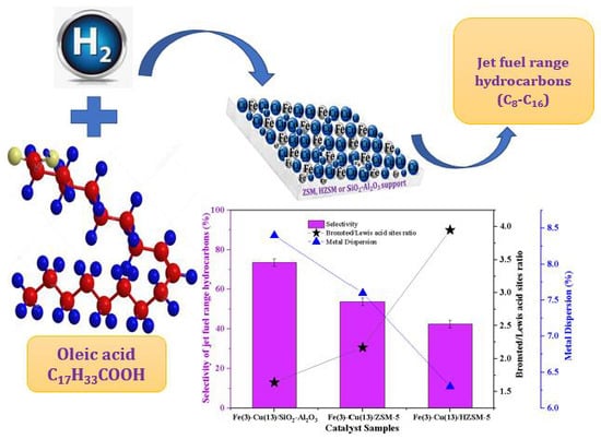
Hydroprocessing of Oleic Acid for Production of Jet-Fuel Range Hydrocarbons over Cu and FeCu Catalysts

Catalysis and Chemical Reaction Engineering Laboratories, University of Saskatchewan, Saskatoon, SK S7N 5A9, Canada
*
Author to whom correspondence should be addressed.
Catalysts 2019, 9(12), 1051; https://doi.org/10.3390/catal9121051
Submission received: 25 October 2019 / Revised: 6 December 2019 / Accepted: 8 December 2019 / Published: 11 December 2019
(This article belongs to the Special Issue Catalysis for the Production of Sustainable Fuels and Chemicals)

Abstract

:
In the present study, a series of monometallic Cu/SiO2-Al2O3 catalysts exhibited immense potential in the hydroprocessing of oleic acid to produce jet-fuel range hydrocarbons. The synergistic effect of Fe on the monometallic Cu/SiO2-Al2O3 catalysts of variable Cu loadings (5–15 wt%) was ascertained by varying Fe contents in the range of 1–5 wt% on the optimized 13% Cu/SiO2-Al2O3 catalyst. At 340 °C and 2.07 MPa H2 pressure, the jet-fuel range hydrocarbons yield and selectivities of 51.8% and 53.8%, respectively, were recorded for the Fe(3)-Cu(13)/SiO2-Al2O3 catalyst. To investigate the influence of acidity of support on the cracking of oleic acid, ZSM-5 (Zeolite Socony Mobil–5) and HZSM-5(Protonated Zeolite Socony Mobil–5)-supported 3% Fe-13% Cu were also evaluated at 300–340 °C and 2.07 MPa H2 pressure. Extensive techniques including N2 sorption analysis, pyridine- Fourier Transform Infrared Spectroscopy (Pyridine-FTIR), X-ray Diffraction (XRD), X-ray Photoelectron Spectroscopy (XPS), and H2-Temperature Programmed Reduction (H2-TPR) analyses were used to characterize the materials. XPS analysis revealed the existence of Cu1+ phase in the Fe(3)-Cu(13)/SiO2-Al2O3 catalyst, while Cu metal was predominant in both the ZSM-5 and HZSM-5-supported FeCu catalysts. The lowest crystallite size of Fe(3)-Cu(13)/SiO2-Al2O3 was confirmed by XRD, indicating high metal dispersion and corroborated by the weakest metal–support interaction revealed from the TPR profile of this catalyst. CO chemisorption also confirmed high metal dispersion (8.4%) for the Fe(3)-Cu(13)/SiO2-Al2O3 catalyst. The lowest and mildest Brønsted/Lewis acid sites ratio was recorded from the pyridine–FTIR analysis for this catalyst. The highest jet-fuel range hydrocarbons yield of 59.5% and 73.6% selectivity were recorded for the Fe(3)-Cu(13)/SiO2-Al2O3 catalyst evaluated at 300 °C and 2.07 MPa H2 pressure, which can be attributed to its desirable textural properties, high oxophilic iron content, high metal dispersion and mild Brønsted acid sites present in this catalyst.

Graphical Abstract

1. Introduction

The aviation sector is a large growing sector which bridges large distances within relatively short time. The total number of international air passengers worldwide in 2018 was 4.4 billion, and this is expected to increase to 7.8 billion in 2036 with Compound Annual Growth Rate (CAGR) of 3.6% according to the prediction made by the International Air Transport Association (IATA). The aviation sector facilitates 35% of world trade by value and it is responsible for transporting 54% of international tourists. In spite of the significance of this sector, it is being faced by challenges over the years. The worldwide aviation industry consumes about 1.7 billion barrels of conventional jet fuel annually [1]. The development of the aviation industry is paralleled with increase in greenhouse gas emissions [2]. According to the air transport action group (ATAG), 895 million tonnes of CO2 was emitted by flights in 2018, which represents about 2% of human-induced emissions. As a result, aviation experts unanimously agreed on three targets that are carbon neutral growth by 2020, fifty percent greenhouse gas emission reduction by 2050 with respect to 2005 as a baseline and lastly, improvement of efficiency of fuel by 1.5% from 2009 to 2020. These are the first set of climate change targets that are streamlined to a particular sector in the world [3]. In order to achieve these targets, different carbon footprint mitigation strategies were devised. They are technological improvements, use of aviation biofuels, airline operations improvements and market-based measures. Sgouridis et al. [4] used the Global Aviation Dynamics (GAID) model to prove that the potential contribution of aviation biofuels and market-based measures is significantly higher than the contribution of the other strategies [4].
Biochemical and thermochemical processes are among the technologies utilized for production of jet fuel from these biomass-based materials [1]. The alternative fuels for air transport include hydroprocessed renewable jet fuels (HRJ), Fischer–Tropsch jet fuels (FTJ), liquid biohydrogen, biomethane and bioalcohol [1]. Hydroprocessed renewable jet fuel has been proven to have the highest jet fuel-to-feed ratio, highest overall energy efficiency, lowest total capital investment and the lowest jet-fuel selling price [4]. Hydroprocessed renewable jet fuels are produced from oil-based feedstocks using hydroprocessing technologies that encompass hydrotreating, hydrodeoxygenation, hydrocracking and isomerization reactions. They find application in conventional aviation turbine engines without modification and without blending with conventional petroleum-derived jet fuels. Hydroprocessed jet fuels are suitable for high altitude flights due to their high cold flow properties [1].
Copper-based catalysts are well known for their preferential selectivity for hydrogenation of C=O bond in carbonyl compounds due to the presence of the unfilled 3D electron levels of metallic copper. These catalysts are also known for their high H2 adsorption and activation abilities [5]. Bykoeva et al. [6] carried out hydrodeoxygenation over a reduced NiCu bimetallic supported catalysts and reported that high catalyst selectivity and catalyst stability were obtained as a result of the inclusion of Cu in the bimetallic catalyst. In spite of all the advantages of using s copper-based catalyst for the hydroprocessing of vegetable oils, they have low affinities for oxygen. To develop a novel catalyst with higher catalyst activity and selectivity, bimetallic catalysts are used due to their often appreciable chemical and electronic behavior as compared to their corresponding monometallic catalysts. Iron has high oxophilicity and can be used to tune the activity and selectivity of copper. Iron has the highest natural abundance, lowest price and rich redox chemistry [7]. Kandel et al. [7] performed hydrodeoxygenation of microalgal oil over the reduced iron-based catalyst. It was found that the high selectivity towards liquid alkanes was due to the Fe-O bond strength; thus providing effective reduction of the microalgal oil to form paraffins. Iron can facilitate hydroprocessing of vegetable oils through binding and subsequent activation of the oxygenates. Addition of iron to copper can also improve the surface area of copper and inhibit its sintering [4]. The supports used in the hydroprocessing of vegetable oil need to complement the activity role played by the active site phase of the catalyst. This can be achieved by synthesizing catalysts’ support of high surface area and pore volume. Light hydrocarbons production can be avoided by using catalyst support of moderate Brønsted acid sites [8].
Alumina, silico-alumino phosphates, zeolites, zirconium oxide and mesoporous materials have been utilized by researchers for the hydroprocessing of vegetable oils [9,10,11]. Kazuhisa et al. [12] worked on the hydroprocessing of jatropha oil over a catalyst supported on ZSM-5 (23 wt% silica–alumina ratio) in a 100 mL autoclave batch reactor at 300 °C, 6.5 MPa H2 pressure, 1 g catalyst/g feed and 12 h reaction time. An 83.8% conversion of jatropha oil, 3.06% CO2 selectivity, 16% C1–C4 hydrocarbon selectivity and 80.7% C10–C20 hydrocarbons yield were obtained. This shows the high activity and selectivity strength of ZSM 5 zeolite-supported catalyst for liquid hydrocarbons. It also shows the cracking effects of ZSM 5, thus indicating it can also be suitable for the hydrodeoxygenation and hydrocracking of vegetable oils to produce jet-fuel hydrocarbon fractions. Mixed support of SiO2 and Al2O3 has also been used for hydroprocessing of vegetable oil. Yanyong et al. [13] examined the hydroprocessing of vegetable oils over the NiMo/SiO2, NiMo/Al2O3 and NiMo/SiO2-Al2O3 catalysts at 350 °C and 4 MPa H2 pressure. The catalysts supported by the mixture of silica and alumina gave the highest and the most desirable iso/normal ratio (0.26). This shows clearly that SiO2-Al2O3-supported catalysts have more preference for hydroprocessing of vegetable oils for bio-jet fuel production as compared to the Al2O3- and SiO2-supported catalysts. Amorphous silica alumina support is viewed as a polymer of Al2O3 on a backbone of SiO2, while crystalline ZSM-5 and HZSM materials are viewed as copolymers of Al2O3 and SiO2 with capacities for ion exchange [14]. These three materials have varying Brønsted acid sites concentrations. Hydroprocessing of vegetable oils for production of jet-fuel range hydrocarbon largely depends on Brønsted acid sites concentrations of the catalysts used [8].
In this work, the catalytic performance on the conversion of model compound of vegetable oils (oleic acid), yield and selectivity of jet-fuel range hydrocarbons were studied over the Cu/SiO2-Al2O3, FeCu/SiO2-Al2O3, FeCu/ZSM-5 and FeCu/HZSM-5 catalysts. These catalysts were characterized for determination of their physicochemical properties and their impacts on product selectivity. The influence of reaction temperature, contact time and catalyst acidity were also investigated.

2. Results and Discussion

2.1. N2- Adsorption/Desorption Measurement
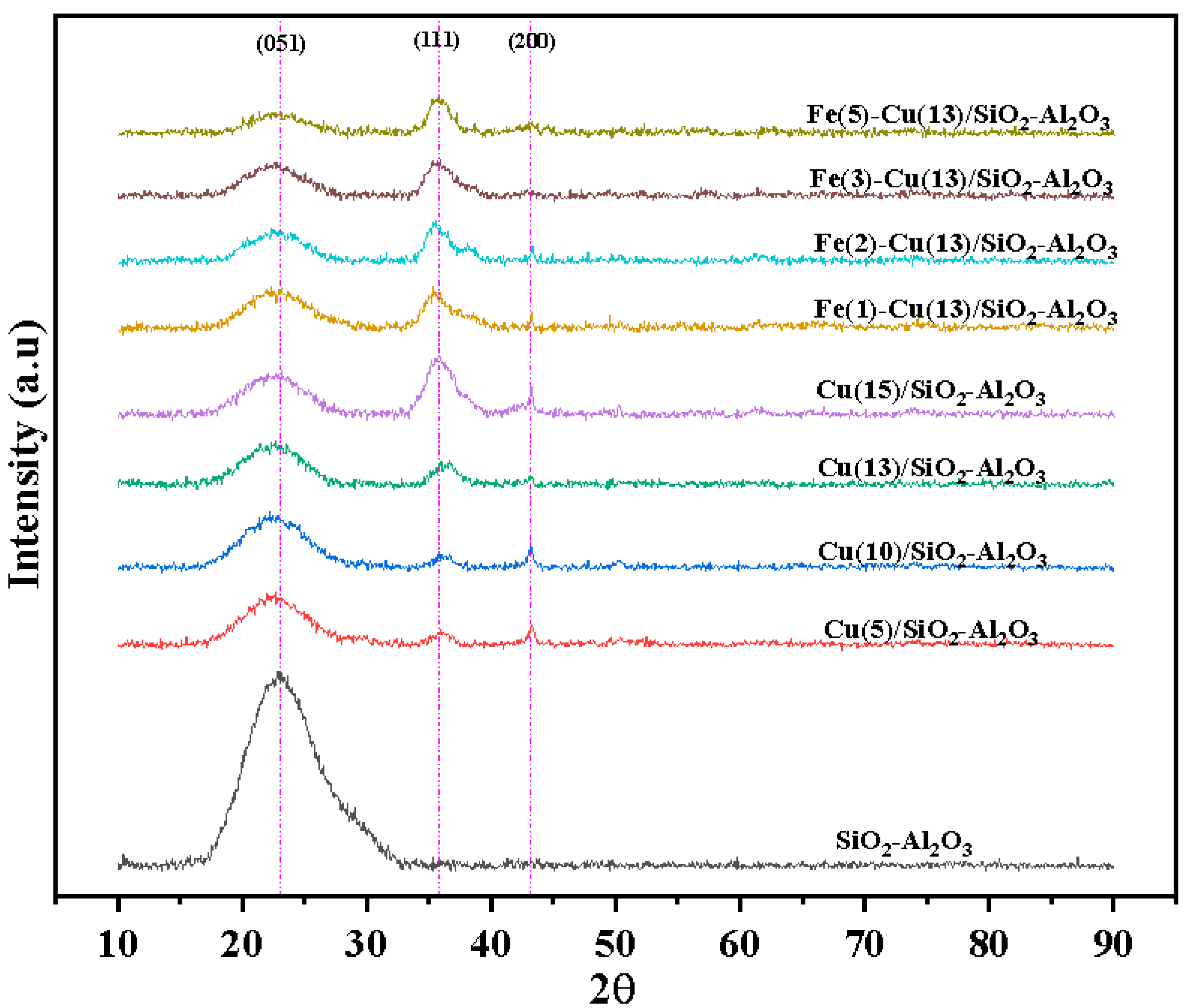
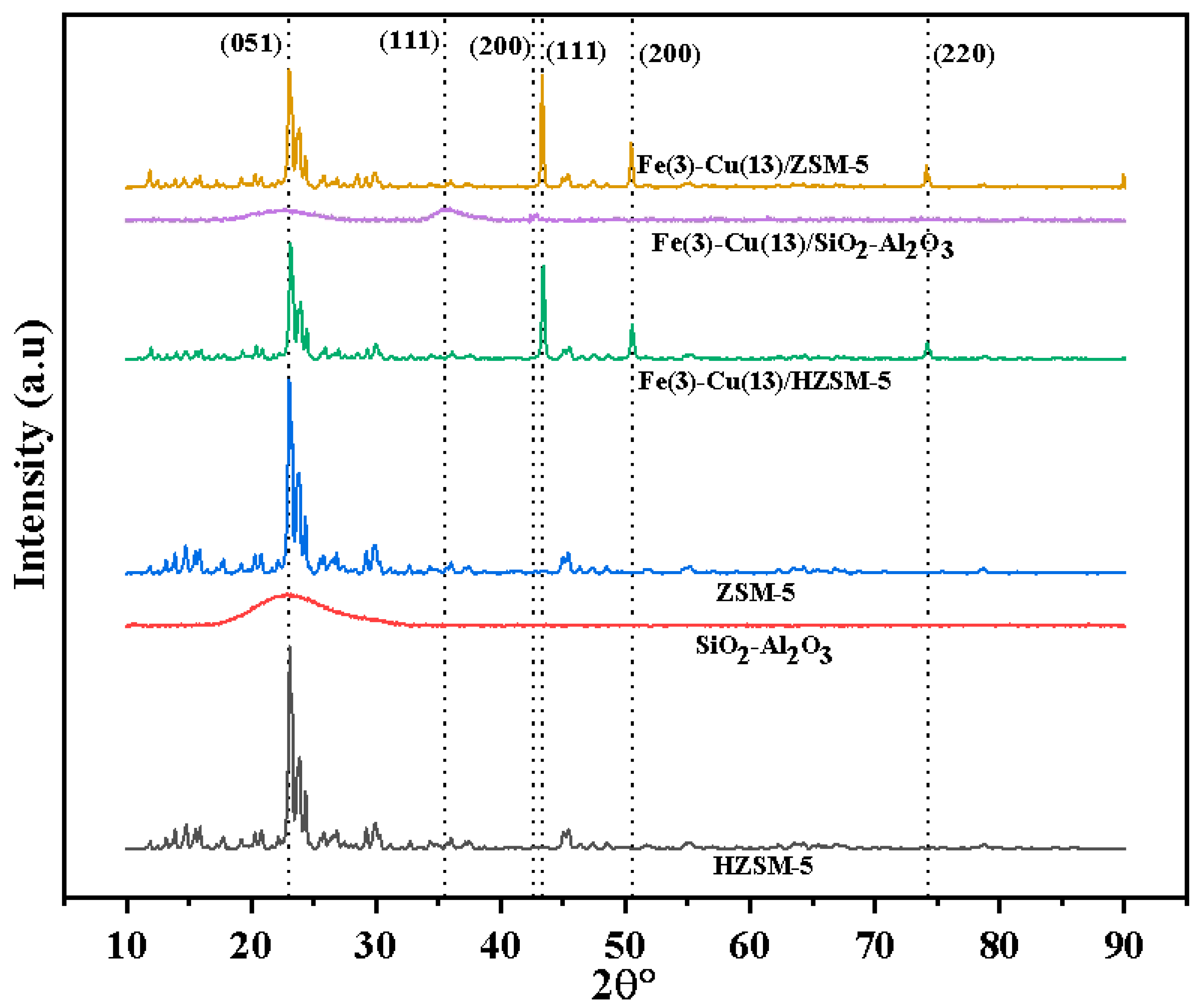
The N2- adsorption/desorption isotherms of all the silica–alumina-supported catalysts and its support are shown in Figure S1. For all the profiles shown in Figure S1, at relatively low pressure, no significant adsorption was observed for the support and the catalysts showed the formation of monolayer of adsorbed molecules of nitrogen gas. Significant adsorption at high relative pressure as shown in Figure S1 indicates adsorption in mesoporous materials [15]. The profiles of the support (SiO2-Al2O3) and the monometallic catalysts exhibit type IV isotherms indicating that the support and the catalysts are mesoporous. Despite different loadings of iron, the profiles of all the FeCu/SiO2-Al2O3 catalysts exhibit type IV isotherm indicating mesoporosity [15]. The pore diameters of the catalysts as shown in Table 1 for all the silica–alumina-supported catalysts and its support confirmed the type IV isotherm in Figure S1. The pore diameters were 4.4–5.7 nm indicating mesoporous nature of material. Out of all the monometallic catalysts, Cu(13)/SiO2-Al2O3 catalyst samples have the largest pore diameter of 5.3 nm. Pore diameter decreases with increase in iron loading (1–5 wt%) as shown in Table 1. This trend can be ascribed to pore blockage.
The N2- adsorption/desorption isotherms of the three catalysts (Fe(3)-Cu(13)/SiO2-Al2O3, Fe(3)-Cu(13)/HZSM-5 and Fe(3)-Cu(13)/ZSM-5) and their respective supports (SiO2-Al2O3, HZSM and ZSM-5 zeolite) are shown in Figure S2. The profiles of SiO2-Al2O3 support and Fe(3)-Cu(13)/SiO2-Al2O3 catalyst exhibit type-IV isotherms. This indicates that the catalysts are mesoporous. Unlike Fe(3)-Cu(13)/SiO2-Al2O3 catalyst and its respective support, Fe(3)-Cu(13)/HZSM-5 and Fe(3)-Cu(13)/ZSM-5 and their respective supports, show no significant adsorption capacity within the relative pressure of 0–0.8. Low nitrogen adsorption occurs at very high relative pressure (p/po > 0.8), indicating a mixed type I–type IV isotherm. It shows the presence of both micro- and mesoporosity in the two catalyst samples and their respective supports [15].
The textural properties of the three catalysts, (Fe(3)-Cu(13)/SiO2-Al2O3, Fe(3)-Cu(13)/HZSM-5 and Fe(3)-Cu(13)/ZSM-5), and their respective supports (SiO2-Al2O3, HZSM-5 and ZSM-5), are also shown in Table 1. The Fe(3)-Cu(13)/SiO2-Al2O3 catalyst and its support have only mesoporous volumes, while other samples have both mesoporous and microporous volumes. The pore volume of all the supports decreases after metals loading due to blockage of the pores. Of all the catalyst samples, Fe(3)-Cu(13)/SiO2-Al2O3 has the largest surface area, pore volume and pore diameter.

2.2. XRD Analysis

The XRD patterns of the silica–alumina-supported catalysts and its support are shown in Figure 1. The 23° diffraction peak on the diffuse XRD pattern of silica alumina support coincides with the literature [16,17,18,19,20] and the broadness of the peaks shows the material is amorphous. The two peaks at 36° and 43° diffraction angles are ascribed to copper (I) oxide [21]. The intensity of the peaks of copper (I) oxide at a 36° diffraction angle increases with copper loading. Diffraction peaks of copper (II) oxide, copper metal, iron oxides and iron were not observed due to their high dispersion on the support. The 42.5° diffraction angle peak attributed to copper (I) oxide [21] in the diffractogram of Fe(3)-Cu(13)/SiO2-Al2O3 catalyst is the most diffuse peak. The decrease in the crystallite size of Cu2O in Fe(1)-Cu(13)/SiO2-Al2O3, Fe(2)-Cu(13)/SiO2-Al2O3 and Fe(3)-Cu(13)/SiO2-Al2O3 with iron loading indicates the promotional effect of iron on the dispersion of copper (see Table 1). Of all the silica–alumina-supported bimetallic catalysts, Fe(3)-Cu(13)/SiO2-Al2O3 catalyst has the lowest Cu2O crystallite size of 5.9 nm. This indicates its potential of being active for hydroprocessing of oleic acid for production of jet-fuel range hydrocarbons (C8–C16).
The XRD patterns of the Fe(3)-Cu(13)/SiO2-Al2O3, Fe(3)-Cu(13)/HZSM-5 and Fe(3)-Cu(13)/ZSM-5 catalyst samples and their respective supports are shown in Figure 2. The X-ray light incident in a periodically arranged crystalline materials scatters in a specific direction and results in high intensity narrow peaks, while the X-ray light incident in amorphous materials scatters in random directions and gives broad peaks. In Figure 2, the discrete X-ray diffraction patterns of HZSM-5 and ZSM-5 supports are sharp Bragg peaks. This shows that these two materials have high degree of crystallinity with long range order. The X-ray diffraction patterns of HZSM-5 and ZSM-5 coincide with that reported in the literature [22,23]. The broad Bragg peak at 23° diffraction angle on the diffuse XRD pattern of amorphous silica alumina shows that it is amorphous and it also coincides with that reported in the literature [16]. The X-ray diffraction patterns of Fe(3)-Cu(13)/HZSM-5 and Fe(3)-Cu(13)/ZSM-5 show clearly the phases of Cu nanoparticles with the 23° sharp peak confirming the supports. In all the XRD patterns of FeCu/HZSM-5 and Fe(3)-Cu(13)/ZSM-5 catalysts, the Bragg peaks at 43°, 51° and 74° diffraction angles, respectively, are ascribed to the presence of Cu nanoparticles [24]. These three characteristic diffraction peaks correspond to the (111), (200) and (220) planes of face-centred cubic structure of copper. The peaks at 36° and 42.5° in the diffractogram of Fe(3)-Cu(13)/SiO2-Al2O3 catalyst are attributed to the presence of copper (I) oxide [21]. The absence of the diffraction peaks of the reduced and oxidized phases of iron in all the samples can be ascribed to the fact that iron may be either present in its noncrystalline phase or in minute quantities below XRD sensitivity.
From the N2- adsorption/desorption measurement, the BET surface area of the silica–alumina support is the highest followed by the ZSM-5 support and HZSM-5 support. The catalyst, Fe(3)-Cu(13)/SiO2-Al2O3 with the highest surface area, pore diameter and pore volume has the lowest copper phase crystallite size.

2.3. Inductively Coupled Plasma-Optical Emission Spectrometry (ICP-OES) and CO Chemisorption Analyses

The actual loadings of iron and copper in Fe(3)-Cu(13)/SiO2-Al2O3, Fe(3)-Cu(13)/ZSM-5 and Fe(3)-Cu(13)/HZSM-5 catalyst samples evaluated using the ICP-OES shows that they are approximately the same as the targeted loading, if rounded up to the nearest whole number. The exact actual loadings of iron and copper of these three catalyst samples in terms of their weight percentage were used in their CO chemisorption analysis. The crystallite size and percentage dispersion surface area of Cu and Fe metals were calculated using the CO chemisorption method and tabulated in Table 2. The metals crystallite size increases in the order of Fe(3)-Cu(13)/SiO2-Al2O3 < Fe(3)-Cu(13)/ZSM-5 < Fe(3)-Cu(13)/HZSM-5. Fe(3)-Cu(13)/SiO2-Al2O3 catalyst has the lowest metals crystallite size as observed from both CO chemisorption analysis and XRD peaks. The Scherrer equation was used to calculate the crystallite size of the copper phase detected from X-ray diffractograms of the catalysts. Cu was detected in the Fe(3)-Cu(13)/ZSM-5 and Fe(3)-Cu(13)/HZSM-5 catalysts with metal crystallite sizes of 33.8 nm and 29.1 nm, respectively, while Cu2O was detected in Fe(3)-Cu(13)/SiO2-Al2O3 catalyst with a crystallite size of 5.9 nm. All the reduced and oxidized phases of iron were not detected in the XRD patterns of the catalysts. These undetected iron phases were detected from XPS and TPR as discussed in later sections. Metals dispersion of the catalyst decreases with increase in their crystallite size as shown in Table 2. Metal dispersion of the three catalysts increases with the surface area of their respective support shown in Table 1. This trend can be attributed to increase in the proportion of catalysts’ surface atoms with respect to the bulk catalysts. Fe(3)-Cu(13)/SiO2-Al2O3 catalyst has the highest metal dispersion and largest surface area as compared to Fe(3)-Cu(13)/ZSM-5 and Fe(3)-Cu(13)/HZSM-5 catalysts.

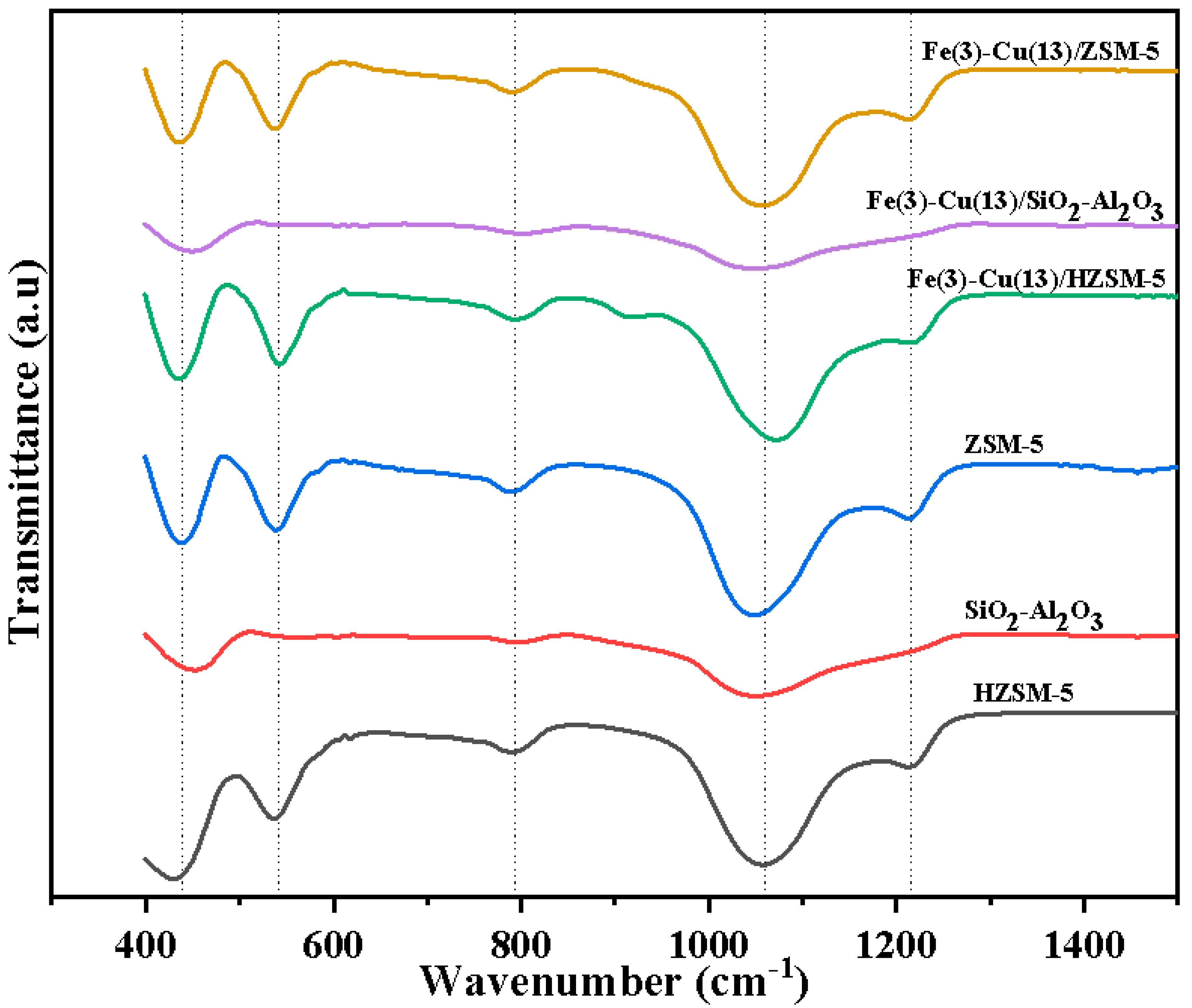
2.4. Fourier Transform Infra-Red Analysis
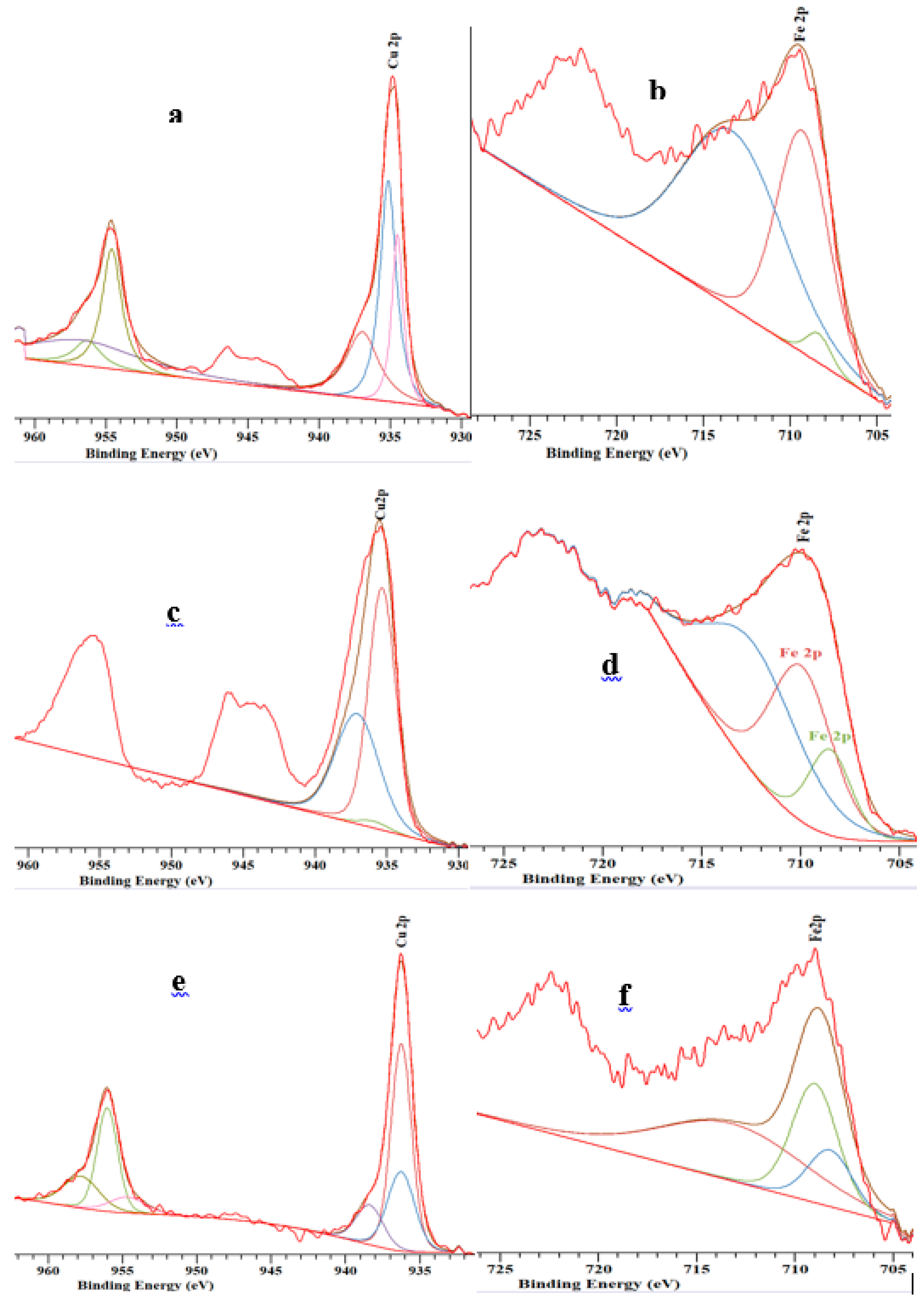
The molecular structure of Fe(3)-Cu(13)/SiO2-Al2O3, Fe(3)-Cu(13)/ZSM-5 and Fe(3)-Cu(13)/HZSM-5 catalysts and their respective supports was analyzed by the FTIR technique in the absorption region of 400–1400 cm−1, as shown in Figure 3. The absorption band detected at 439 cm−1 wavenumber can be ascribed to Si-O bending. The framework vibration at 537 cm−1 wavenumber on the ZSM-5 and HZSM-5 support are characteristics of five membered rings tetrahedron shaped MFI zeolites. The absorption detected at 791 cm−1, 1065 cm−1 and 1210 cm−1 wavenumbers can be ascribed to the external symmetric stretch, internal asymmetric stretch and external asymmetric stretch, which are typical for extremely siliceous materials [18,25]. The peaks were more intense in ZSM-5 and HZSM because of their higher silica–alumina ratio as compared to that of the silica–alumina support. There was a slight peak shift to a higher wavenumber at 537 cm−1 after Cu and Fe impregnation on HZSM-5 in the framework vibration ascribed to five membered rings tetrahedron shaped MFI zeolites. There was also slight shift of peaks to a higher wavenumber at 1065 cm−1 after Cu and Fe impregnation on ZSM-5 and HZSM-5 in the absorption band ascribed to internal asymmetric stretch of extremely siliceous materials. These shifts of FTIR peaks after impregnation of Cu and Fe are due to change in bond length of the aluminosilicate frameworks in the catalyst samples [18,25].

2.5. XPS

The XPS spectra of the Fe(3)-Cu(13)/SiO2-Al2O3, Fe(3)-Cu(13)/ZSM-5 and Fe(3)-Cu(13)/HZSM-5 catalyst samples were fitted for both Cu2p and Fe2p using the CasaXPS software as shown in Figure 4. The analysis confirmed the presence of iron and copper in their oxides and reduced states in all the three catalyst samples [26,27,28,29,30,31,32,33,34,35]. Cu2p1/2 and Cu2p3/2 XPS peaks were observed at 935–937 eV and 954–956 eV respectively, while Fe2p1/2 and Fe2p3/2 XPS peaks were observed at 721–723 eV and 708–713 eV respectively. The weak satellite peak at 945 eV binding energy on the XPS spectra of Fe(3)-Cu(13)/HZSM and Fe(3)-Cu(13)/ZSM catalysts confirms the presence of Cu2O, while the strong satellite peak at the similar binding energy on the XPS spectra of Fe(3)-Cu(13)/SiO2-Al2O3 can be attributed to Cu2+ phase [31]. The atomic compositions of the metal oxides and reduced metals obtained from the XPS spectra fitting were tabulated in Table 3. All the three catalyst samples consist of significant atomic composition of copper and iron in their oxide state, owing to the passivation of the surface of the catalysts during their synthesis. The results also show that all the catalyst samples consist of Fe2O3 in larger quantities as compared to FeO at the surface. The highest surface atomic composition of oxophilic iron metal was observed in the FeCu/SiO2-Al2O3 catalyst as revealed from XPS fitting. The varying composition of metals and their oxides in all the catalysts can be ascribed to their different metal–support interactions.

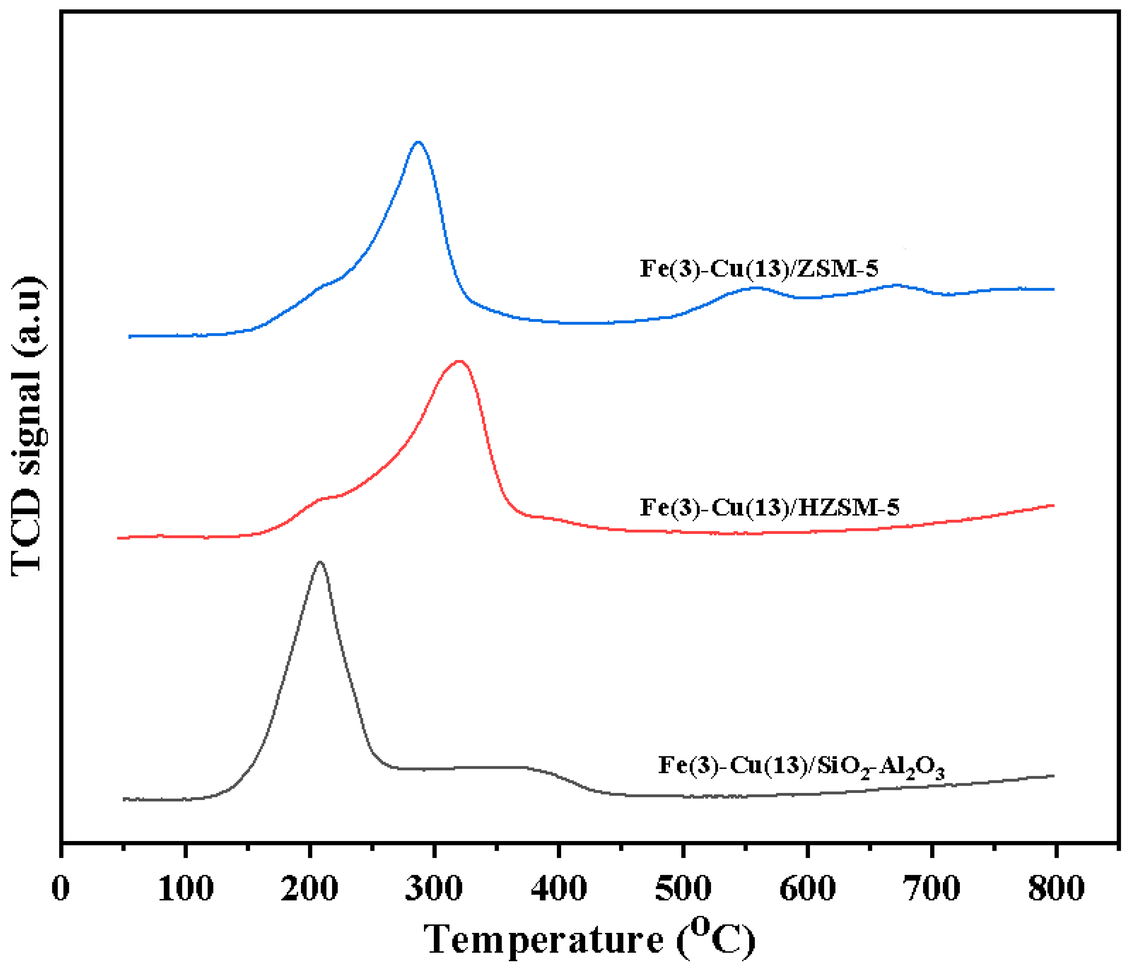
2.6. H2-TPR Analysis

The H2-TPR profiles of the Fe(3)-Cu(13)/SiO2-Al2O3, Fe(3)-Cu(13)/HZSM-5 and Fe(3)-Cu(13)/ZSM-5 catalysts are shown in Figure 5. The profiles confirmed the findings from XRD and XPS analyses that despite reduction of the catalyst samples during synthesis, they still consist of oxides of Cu. The H2 uptake from the TPR result is in the order of Fe(3)-Cu(13)/SiO2-Al2O3 >Fe(3)-Cu(13)/ZSM-5 > Fe(3)-Cu(13)/HZSM-5 as shown in Table 4. The reduction peak temperature at 207 °C, 289 °C and 321 °C in the respective profiles of Fe(3)-Cu(13)/SiO2-Al2O3, Fe(3)-Cu(13)/ZSM-5 and Fe(3)-Cu(13)/HZSM-5 are ascribed to the reduction of copper oxides to copper while the hump above 300 °C in all the three TPR profiles are attributed to reduction of iron oxides to iron [33]. The reduction peak temperature from the TPR profiles and the crystallite size of the catalysts obtained from CO chemisorption analysis are in the same order of Fe(3)-Cu(13)/SiO2-Al2O3 < Fe(3)-Cu(13)/ZSM-5 < Fe(3)-Cu(13)/HZSM-5. Low reduction peak temperature and low crystallite size indicate weak metal–support interaction, therefore the Fe(3)-Cu(13)/SiO2-Al2O3 catalyst has the weakest metal–support interaction and highest metal dispersion [34,35].

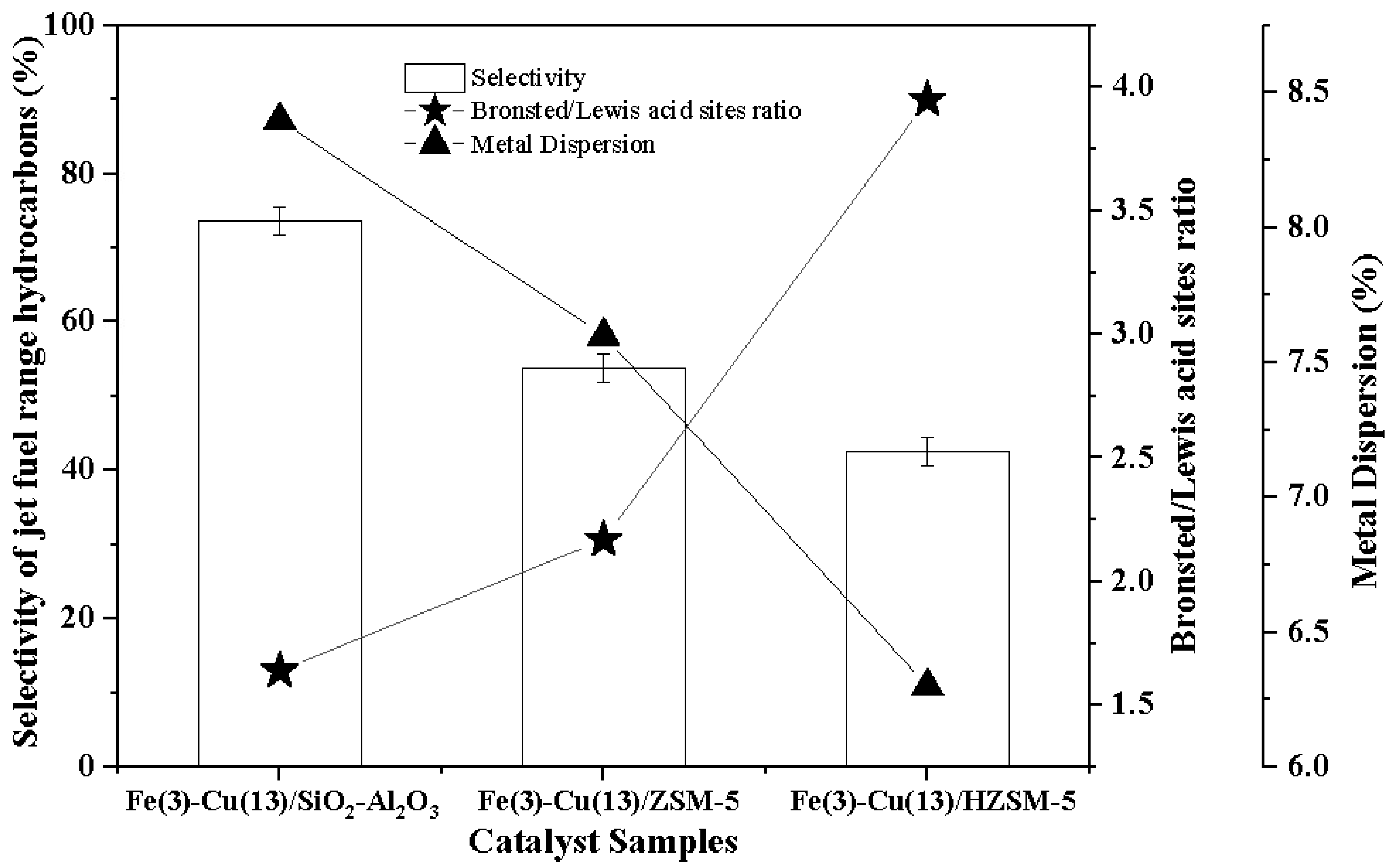
2.7. Pyridine FTIR Analysis

Pyridine, ammonia and acetonitrile can be used to determine the Brønsted and Lewis acid sites of the catalysts. In this work, pyridine was used as molecular probe and it shows a clear distinction between the Brønsted and Lewis acid sites. Moreover, the kinetic diameter of pyridine is 0.57 nm which is lower than the 2.1–5.7 nm pore size of the catalysts [36]. Catalysts of high Brønsted/Lewis acidity ratio favours cracking and is also not selective for dehydrogenation [37]. Cracking is desired for hydroprocessing of oleic acid for production of jet-fuel range hydrocarbons and dehydrogenation is undesirable. Pyridine FTIR spectra and Brønsted/Lewis acid sites ratio of Fe(3)-Cu(13)/SiO2-Al2O3, Fe(3)-Cu(13)/ZSM-5 and Fe(3)-Cu(13)/HZSM-5 catalysts were shown in Figure S3 and Figure 6, respectively. The Brønsted/Lewis acid sites ratio increases in the order of Fe(3)-Cu(13)/SiO2-Al2O3 < Fe(3)-Cu(13)/ZSM-5 < Fe(3)-Cu(13)/HZSM-5 as shown in Figure 6. Fe(3)-Cu(13)/HZSM-5 and Fe(3)-Cu(13)/ZSM-5 catalysts have higher Brønsted/Lewis acid sites ratio as compared to the Fe(3)-Cu(13)/SiO2-Al2O3 catalyst. This indicates that the MFI zeolite catalysts are richer in Brønsted acid sites. Fe(3)-Cu(13)/HZSM-5 catalyst have higher Brønsted/Lewis acid sites ratio in comparison with Fe(3)-Cu(13)/ZSM-5 due to the protonation of the ZSM-5 support. Brønsted/Lewis sites ratio of the catalyst as shown in Figure 6 has significant influence on selectivity of jet-fuel range hydrocarbons as discussed in the later section.

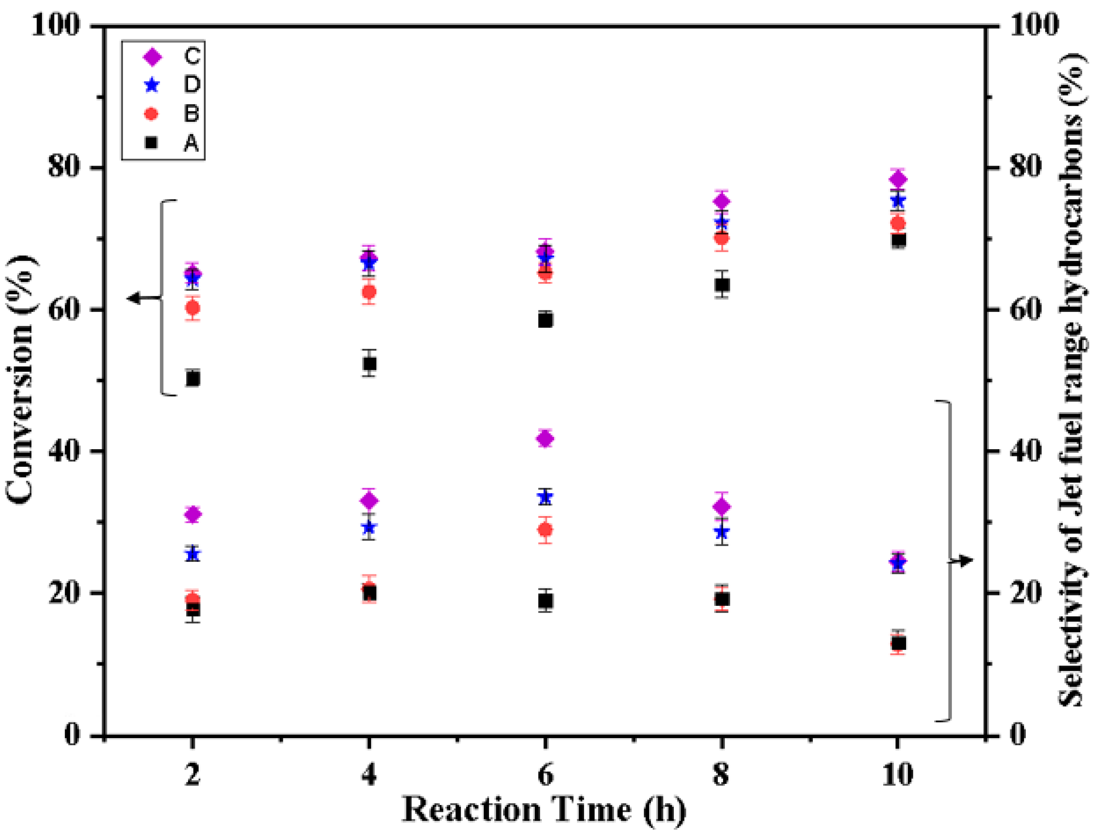
2.8. Catalyst Evaluation

The products obtained from the hydroprocessing reaction were analyzed based on oleic acid conversion, yield and selectivity of jet-fuel range hydrocarbons. The results obtained from the gas chromatography (GC) analysis show that reaction time, temperature and catalysts have significant effects on the conversion of oleic acid, yield and selectivity of the jet-fuel range hydrocarbons. The error % for all the result was within ± 5%. Figure 7 shows the results obtained from the evaluation of Cu(5)/SiO2-Al2O3, Cu(10)/SiO2-Al2O3, Cu(13)/SiO2-Al2O3 and Cu(15)/SiO2-Al2O3 catalysts at 340 °C, 2.07 MPa hydrogen pressure and 5% catalyst/feed ratio. The effects of reaction times (2–10 hours) on the conversion of oleic acid is shown in Figure 7. The conversion of oleic acid increases with time for all the four catalysts. The highest oleic acid conversion obtained was 78.4% at 10 hours from the evaluation of Cu(13)/SiO2-Al2O3 catalyst. The effects of reaction time (2–10 hours) on the selectivity of jet-fuel range hydrocarbons are shown in Figure 7. The highest selectivity of jet-fuel range hydrocarbons obtained was 41.9% respectively at 6 hours. Unlike conversion of oleic acid, which increases with time, the selectivity of jet-fuel range hydrocarbons initially increases and later decreases with reaction time due to subsequent cracking of the jet-fuel range hydrocarbons to lighter hydrocarbons shown in Table S1. Oleic acid consists of macromolecules requiring catalyst of high pore size for easy internal diffusion. Cu(13)/SiO2-Al2O3 performs better than the other three monometallic catalysts due to its high pore diameter (5.3 nm), which implies high accessibility of oleic acid and hydrogen to the active site (copper) of the catalyst.
The effects of reaction time (2–10 hours) on oleic acid conversion and selectivity of jet-fuel range hydrocarbons over the FeCu/SiO2-Al2O3 catalysts are shown in Figure 8. The conversion of oleic acid increases with time for all the catalysts. The highest oleic acid conversion obtained was 98% at 10 hours from the evaluation of Fe(3)-Cu(13)/SiO2-Al2O3 catalyst. The highest selectivity of jet-fuel range hydrocarbons obtained was 53.8% at 10 hours. The better performance of Fe(3)-Cu(13)/SiO2-Al2O3 catalyst is due to its smaller crystallite size and high dispersion of copper and iron metals and high reducibility of metals as compared to the other three catalysts.
The effects of reaction times (2–10 h) and temperature (300–340 °C) on oleic acid conversion, yield and selectivity of jet-fuel range hydrocarbons over the Fe(3)-Cu(13)/SiO2-Al2O3, Fe(3)-Cu(13)/HZSM-5 and Fe(3)-Cu(13)/ZSM-5 catalysts are shown in Figure 9, Figure 10 and Figure 11 and Table 5. The product distribution of C8–C16 is also shown in Table S2. The conversion of oleic acid increases with reaction time and temperature for all the three catalyst samples. The conversion approximately stabilizes between 8 to 10 h for Fe(3)-Cu(13)/SiO2-Al2O3 catalyst at 320–340 °C, Fe(3)-Cu(13)/ZSM catalyst at 300–340 °C and, Fe(3)-Cu(13)/HZSM catalyst at 320–340 °C.
The highest yield and selectivity of jet fuel hydrocarbons were recorded for Fe(3)-Cu(13)/SiO2-Al2O3 catalyst at 300 °C as shown in Figure 11 and Table 5. The total number of surface atoms of Cu and Fe per the total number of atoms present in the catalyst increases with surface area. Catalysts of high Brønsted/Lewis acid site ratio favours cracking, while oligomerization and dehydrogenation are favoured by catalysts of low Brønsted/Lewis acid sites ratio [37]. The internal diffusion calculation was carried out using the Weisz–Prater criterion [38]. The Weisz–Prater parameter for this reaction was 3.6 × 10⁻⁷, which is much less than 1 indicating that the internal diffusion in catalyst particles is absent. The experimental data show that with reaction time, more lighter hydrocarbons (C5–C7) were produced from jet-fuel range hydrocarbons (C8–C16) due to deep and mild cracking. This may be due to acidic nature of the catalysts used in this study. Hydroprocessing reactions of fatty acids, triglycerides and vegetable oils require catalysts of mild Brønsted acid sites to produce jet-fuel range hydrocarbons. Catalysts of high Brønsted sites have higher tendency of producing hydrocarbons that are lighter than the jet-fuel range hydrocarbons [8]. Catalysts of low Brønsted acid sites favor only the hydrodeoxygenation reaction with no sufficient cracking strength. The Fe(3)-Cu(13)/SiO2-Al2O3 catalyst has mild Brønsted/Lewis acid sites ratio as proven from Figure 6. The relationship between the metal dispersion, Brønsted/Lewis acid sites ratio and selectivity of jet-fuel range hydrocarbons at 300 °C and 2.07 MPa H2 pressure over the Fe(3)-Cu(13)/SiO2-Al2O3, Fe(3)-Cu(13)/ZSM-5 and Fe(3)-Cu(13)/HZSM-5 catalysts are shown in Figure 6. Fe(3)-Cu(13)/HZSM-5 catalyst has the lowest metal dispersion and Brønsted/Lewis acid sites ratio and the lowest selectivity of jet-fuel range hydrocarbons, while the Fe(3)-Cu(13)/SiO2-Al2O3 catalyst has the highest metal dispersion and Brønsted/Lewis acid sites ratio and the highest selectivity of jet-fuel range hydrocarbons. The productivity of Fe(3)-Cu(13)/SiO2-Al2O3, Fe(3)-Cu(13)/ZSM-5 and Fe(3)-Cu(13)/HZSM-5 catalysts in terms of g jet fuel/g catalyst/h and g jet fuel/m2 metals surface area/g catalyst are shown in Table S3. The Fe(3)-Cu(13)/SiO2-Al2O3 catalyst is the most productive catalyst, with 1.0 g jet fuel/g catalyst/h and 2.6 g jet fuel/m2 metals surface area/g catalyst. The Fe(3)-Cu(13)/SiO2-Al2O3 catalyst is the most promising when the entire temperature range(300–340 °C) is considered. This can be attributed to the relatively low Brønsted/Lewis acid sites ratio [8], high Cu and Fe metals dispersion, high pore volume, specific surface area of the Fe(3)-Cu(13)/SiO2-Al2O3 catalyst and high surface composition of oxophilic iron metal observed from XPS fitting.

3. Experimental Methods

3.1. Catalyst Synthesis

Reduced Cu/SiO2-Al2O3, FeCu/SiO2-Al2O3, FeCu/ZSM-5 and FeCu/HZSM-5 bimetallic catalysts were synthesized using diffusional impregnation and co-impregnation techniques.

3.1.1. Chemical and Materials

Oleic acid (code number: 364525) and amorphous silica–alumina catalyst support (SiO2/Al2O3: 6.25, code number: 343358) were procured from Sigma-Aldrich (Missouri, U.S.A). Copper (II) nitrate hemipentahydrate (code number: 467855) and iron nitrate nonahydrate (code number: 254223) were purchased from ES company (New Jersey, U.S.A) and Millipore (Canada) Ltd (Ontario, Canada) respectively. ZSM-5 zeolite (code number: CB2314, SiO2/Al2O3: 23) was supplied by zeolyst international (Kansas, U.S.A).

3.1.2. Support Preparation

HZSM support (SiO2/Al2O3: 23) was prepared by exchanging ZSM-5 with a 1.0 M ammonium nitrate solution at 100 °C for 3 h followed by calcination in air at 550 °C for 4 h [39]. Two commercial supports (amorphous silica alumina and ZSM-5) were used alongside with the synthesized HZSM.

3.1.3. Catalyst Preparation by Impregnation

Monometallic 5, 10, 13 and 15 wt% Cu/SiO2-Al2O3 catalysts were synthesized using copper (II) nitrate hemipentahydrate as precursor for copper. The solution of the precursor was impregnated on amorphous silica alumina using diffusional impregnation technique and then the mixture was dried overnight at 100 °C in a drying oven for each of the four catalyst samples. For instance, 15 g of 13 wt% Cu/SiO2-Al2O3 was synthesized by impregnating 7.1 g of copper (II) nitrate hemipentahydrate on 13.1 g of amorphous silica alumina. The dried mixture was calcined in air in a muffle furnace at 450 °C for 6 hours at 1 °C /min heating rate, reduced under 50 mL/min H2 flow at 400 °C for 4 hours at 1 °C/min heating rate and passivated with 1% O2/N2 flowing at 50 mL/min for 1 hour ambient temperature. Thirteen wt% Cu/SiO2-Al2O3 was selected from the four catalyst samples for iron promotional effect studies.
Bimetallic Fe(1)-Cu(13)/SiO2-Al2O3, Fe(2)-Cu(13)/SiO2-Al2O3, Fe(3)-Cu(13)/SiO2-Al2O3, Fe(1)-Cu(13)/SiO2-Al2O3 catalysts were synthesized using copper (II) nitrate hemipentahydrate and iron nitrate nonahydrate as precursors for copper and iron respectively. Copper (II) nitrate hemipentahydrate solution and iron nitrate nonahydrate solution was first impregnated on amorphous silica alumina using diffusional co-impregnation method and then the mixture was dried overnight at 100 °C. For instance, 15 g of Fe(3)-Cu(13)/SiO2-Al2O3 was synthesized by co-impregnating 7.1 g of copper (II) nitrate hemipentahydrate and 3.3 g of iron nitrate nonahydrate solution on 12.6 g of amorphous silica alumina. The dried co-impregnated mixture was calcined in air in a muffle furnace at 450 °C for 6 hours by heating at 1 °C/min, reduced under 50 mL/min H2 flow at 400 °C for 4 hours at 1 °C/min heating rate and passivated with 1% O2/N2 flowing at 50 mL/min for 1 hour ambient temperature. Fe(3)-Cu(13)/SiO2-Al2O3 catalyst was selected as the catalyst from the four bimetallic catalysts for supports optimization studies.
For effective support optimization, Fe(3)-Cu(13)/ZSM-5 and Fe(3)-Cu(13)/HZSM-5 catalysts were also synthesized using the same procedure as Fe(3)-Cu(13)/SiO2-Al2O3 catalyst.

3.2. Catalyst Characterization

3.2.1. ICP-OES

The mass compositions of copper and iron in Fe(3)-Cu(13)/SiO2-Al2O3, Fe(3)-Cu(13)/ZSM-5 and Fe(3)-Cu(13)/HZSM-5 catalysts were evaluated using a concentrated mixture of HF/HNO3/HClO3 to digest 0.125 g of each catalyst samples to dryness in a Teflon tube to analyze copper and also utilizing Ox automated fusion instrument to fuse the combination of Lithium metaborate and Lithium tetraborate mixture with 0.1 g of each catalyst samples in a graphite crucible for analyze iron. Dilute HNO3 was then used to dissolve the dry residue and fused product obtained respectively from the copper and iron analyses and they were analyzed with Perkin Elmer ICP-OES (Optima 5300 DV) in the geoanalytical laboratory of the Saskatchewan Research Council.

3.2.2. N2-Adsorption/Desorption Measurement

Micrometrics ASAP 2020 instrument was used to characterize all the catalyst samples and their respective supports with the BET method. Each catalyst sample was degassed in a sealed tube in vacuum conditions at 250 °C for 5 h and evacuated until a static pressure of less than 1.33 Pa was obtained. Physisorption analysis was then carried out with N2 at −196 °C.

3.2.3. XRD

X-ray diffraction patterns of all the catalyst samples and their respective supports were obtained with a monochromatic Cu Kα radiation source of 0.15406 nm wavelength using an Ultima IV instrument from Rigaku Instruments. The normal scan rate of the equipment is 2° scan/min within 10–80° diffraction angle and 0.02 step size. The average crystallite size of the intense XRD peaks obtained for all the catalyst samples was calculated using Equation (4).
L =   k λ β cos θ
k = constant; λ = wavelength of the source of X-ray; β= Full width at half maxima; θ= half of the Bragg angle.

3.2.4. XPS

XPS was used to study the phases of the active sites (Copper and Iron) at the surface of Fe(3)-Cu(13)/SiO2-Al2O3, Fe(3)-Cu(13)/ZSM-5 and Fe(3)-Cu(13)/HZSM-5 catalyst samples. Kratos (Manchester city, United Kingdom) AXIS Supra system equipped Rowland circle monochromated source of 1486.6 eV Al K-α was used for XPS measurements for all three synthesized catalyst samples. Three high-resolution regional scans were carried out using 0.05 eV steps with 20 eV pass energy. An accelerating voltage of 15,000 eV and an emission current of 0.015 A were used for the analysis.

3.2.5. FTIR Spectroscopy.

A JASCO FT-IR 4100 instrument was used to identify the functional groups of the all the synthesized catalyst samples and their respective supports. For analysis, 3 mg of sample was uniformly mixed with 0.4 g of KBr pellets. Qualitative analysis of the functional groups of the catalyst samples were obtained with 32 scans of 4 cm−1 nominal resolution. The IR spectra of pelletized samples were later recorded in transmission mode in the wavenumber range of 400–1400 cm−1.

3.2.6. CO Chemisorption

The metal dispersion and crystallite size of Fe(3)-Cu(13)/SiO2-Al2O3, Fe(3)-Cu(13)/ZSM-5 and Fe(3)-Cu(13)/HZSM-5 catalyst samples were measured using the Micrometrics ASAP 2020 chemisorption system. The catalyst samples were heated to 350 °C at 10 °C/min ramp rate in the presence of H2. They were then held for 2 h and later cooled down to 35 °C and evaluated to a static pressure below 1.3 × 10⁻⁵ N/m2. Pulses of CO were passed over the evacuated sample and the total CO uptake was measured at 35 °C. Stoichiometric factor of 0.5 mole of CO per metal atom was used for copper and iron.

3.2.7. Temperature Programmed Reduction (TPR)

H2-TPR of Fe(3)-Cu(13)/SiO2-Al2O3, Fe(3)-Cu(13)/ZSM-5 and Fe(3)-Cu(13)/HZSM-5 catalyst samples were conducted at 101.3 KPa using Micrometrics Auto Chem II 2920 analyzer. 10% H2/Ar was circulated to 0.05 g of each sample in a steel tube at 50 cm3/min and the temperature was increased to 850 °C from ambient temperature at 10 °C/min. As the temperature increases, the reaction of the catalyst and hydrogen gas proceeds to produce water vapour, which was trapped through a cold trap by outlet stream circulation. The exit gas stream was channeled via a calibrated thermal conductivity detector (TCD) for the detection of varying H2 concentrations due to catalyst reduction.

3.2.8. Pyridine FTIR

The FTIR technique was utilized to study the nature of acid sites of Fe(3)-Cu(13)/SiO2-Al2O3, Fe(3)-Cu(13)/ZSM-5 and Fe(3)-Cu(13)/HZSM-5 catalyst samples and their respective supports using a wavenumber region of pyridine (1400–1700 cm−1). A sample cylindrical cup in a Spectrotech diffuse reflectance in situ cell equipped with a thermocouple and zinc selenide windows was loaded with 0.01 g of each catalyst sample. These three catalyst samples and their respective supports were pretreated at 350 °C in order to remove any adsorbed water on the catalyst surface. Pyridine vapor was then passed over each catalyst sample at 100 °C for 1 hour to obtain pyridine chemisorbed samples. After adsorption of pyridine, nitrogen gas was used for the stabilization of the catalyst samples at 100 °C for 30 min with a ramping rate of 5 °C/min, then allowed to cool to ambient temperature. The samples were analyzed with a JASCO FT-IR 4100 instrument in the wavenumber range of 1400–1700 cm−1 and their respective IR spectra were recorded. Brønsted/Lewis acid sites ratio of all the three catalyst samples were calculated using Equation (5):
C B C L = IMEC ( B ) 1 IMEC ( L ) 1 . IT ( B ) IT ( L )
where, C B C L = r a t i o   o f   c o n c e n t r a t i o n   o f   B r o n s t e d   a n d   L e w i s   a c i d   s i t e s . IMEC(B) and IMEC(L) are integrated molar extinction coefficients (cm/µmol) of Brønsted and Lewis acid sites, respectively. IT(B) and IT(L) are integrated transmittances of Brønsted and Lewis acid sites, respectively [40,41].

3.3. Catalyst Evaluation

The catalytic reactions were carried out in a Parr stirred batch reactor. It is made in a bench top with moveable vessel mounting style. The capacity of the reactor vessel is 300 mL, with dimension of 2.5 inches diameter and 4 inches depth and the reactor is connected to a Parr 4848 reactor controller. The catalyst samples were evaluated in this Parr batch reactor. Two g of each of the catalyst samples and 40 g of oleic acid were placed in the reactor and hydrogen gas was used to pressurize the reactor to 2.07 MPa. Cu/SiO2-Al2O3 and FeCu/SiO2-Al2O3 catalysts were evaluated at 340 °C. The temperatures of the reaction involving support optimization studies were set at 300, 320 and 340 °C. The impeller speed and reaction time were 500 rpm and 10 h, respectively. The liquid product samples were collected at 2 h interval, filtered and diluted using chloroform as the diluent. The solution of liquid product samples was analyzed with GC (Agilent 7890A) equipped with a flame ionization detector (FID). A 30 m long DB-5 capillary column with 0.25 mm inner diameter was used. The temperature of the oven was programmed to start from 40 °C for 2 min and increased to 280 °C at 10 °C/min ramping rate with a 5 min final hold time. One µL of each product sample was injected with a split ratio of 10:1 into the column. C6–C20 aliphatic hydrocarbons were used as external standard to quantify the liquid hydrocarbons produced. The gaseous products were analyzed using an online GC equipped with FID and catalyst performance was evaluated based on oleic acid conversion and jet-fuel range hydrocarbons (C8–C16) selectivity as given below.
Oleic   acid   conversion   ( % ) = ( amount   of   oleic   acid   reacted amount   of   oleic   acid   initially   taken )   × 100
Selectivity   of   jet fuel   range   hydrocarbons   ( % ) = ( amount   of   jet fuel   range   hydrocarbons amount   of   products   formed )   × 100
Yield   of   jet fuel   range   hydrocarbons   ( % ) = ( amount   of   jet fuel   range   hydrocarbons   amount   of   oleic   acid   initially   taken ) × 100

4. Conclusions

In summary, copper metal with optimized loading on silica alumina support was suitable for hydroprocessing of oleic acid for production of jet-fuel range hydrocarbons. The best monometallic catalyst performance with 41.9% selectivity of jet-fuel range hydrocarbons (C8–C16) was achieved at 340 °C, 2.07 MPa H2 pressure and 6 hours reaction time over the catalyst with the largest pore size of 5.3 nm (Cu(13)/SiO2-Al2O3).
Optimization studies of iron promotional effects for hydroprocessing of oleic acid for production of jet-fuel range hydrocarbons on the Cu(13)/SiO2-Al2O3 catalyst showed more promising result in comparison with the monometallic copper catalysts due to effect of iron loading in lowering metal crystallite size indicating increase in metal dispersion. The best catalyst performance with 51.8% yield and 53.8% selectivity of jet-fuel range hydrocarbons was achieved over the iron-promoted copper catalyst with the lowest crystallite size (Fe(3)-Cu(13)/ SiO2-Al2O3) at 340 °C, 2.07 MPa and 10 h of reaction time.
Support optimization studies on HZSM-5, ZSM-5 and SiO2-Al2O3 supports reveal that Fe(3)-Cu(13)/ SiO2-Al2O3 catalyst gives the best catalyst performance with 59.5% yield and 73.6% selectivity of jet-fuel range hydrocarbons. This promising performance was attributed to its large pore diameter, large pore volume and large surface area; low crystallite size and weak metal–support interaction from H2-TPR analysis, indicating, high metal dispersion from CO chemisorption analysis, high oxophilic iron content from XPS fitting and mild Brønsted acid sites from pyridine FTIR analysis.

Supplementary Materials

The following are available online at https://www.mdpi.com/2073-4344/9/12/1051/s1, Figure S1. N2-adsorption isotherms of SiO2-Al2O3, Cu(5)/SiO2-Al2O3, Cu(10)/SiO2-Al2O3, Cu(13)/SiO2-Al2O3 and Cu(15)/SiO2-Al2O3, Fe(1)-Cu(13)/SiO2-Al2O3, Fe(2)-Cu(13)/SiO2-Al2O3, Fe(3)-Cu(13)/SiO2-Al2O3 and Fe(5)-Cu(13)/SiO2-Al2O3 catalysts. Figure S2. N2-adsorption isotherms of SiO2-Al2O3, ZSM-5 and HZSM-5 supports; Fe(3)-Cu(13)/SiO2-Al2O3, Fe(3)-Cu(13)/ZSM-5 and Fe(3)-Cu(13)/HZSM catalysts. Figure S3. Py-FTIR spectra of SiO2-Al2O3, ZSM-5 and HZSM-5 supports; Fe(3)-Cu(13)/SiO2-Al2O3, Fe(3)-Cu(13)/ZSM-5 and Fe(3)-Cu(13)/HZSM catalysts. Table S1: Selectivity of lighter hydrocarbons at t: 8 h; T: 300 °C, and PH2: 2.07 MPa H2 pressure. Table S2: Selectivity of C8–C16 hydrocarbons at t: 8 h; T: 300 °C, and PH2: 2.07 MPa H2 pressure. Table S3: Catalysts productivity towards C8–C16 hydrocarbons at t: 8 hours; T: 300–340 °C, and PH2: 2.07 MPa H2 pressure.

Author Contributions

Conceptualization, A.A.A.; writing—original draft preparation, A.A.A.; writing—review and editing, A.A.A., P.E.B. and A.K.D.; methodology, A.A.A., A.K.D., Y.H. and P.E.B.; formal analysis, A.A.A.; investigation, A.A.A. and P.E.B.; resources, A.K.D.; data curation, A.A.A.; supervision, A.K.D. and Y.K.D.; project administration, A.K.D.; funding acquisition, A.K.D.

Funding

This Research was funded by Canada Research Chairs (CRC) and Natural Sciences and Engineering Research Council of Canada (NSERC).

Acknowledgments

The authors acknowledge Canada Research Chair (CRC) Program and Natural Sciences and Engineering Research Council of Canada (NSERC) for funding this research.

Conflicts of Interest

The authors declare no conflicts of interest.

References

  1. Wang, W.; Tao, L. Bio-jet fuel conversion technologies. Renew. Sust. Energ. Rev. 2016, 53, 801–822. [Google Scholar] [CrossRef] [Green Version]
  2. Kieckhäfer, K.; Quante, G.; Müller, C.; Spengler, T.S.; Lossau, M.; Jonas, W. Simulation-Based Analysis of the Potential of Alternative Fuels towards Reducing CO2 Emissions from Aviation. Simulation-Based Analysis of the Potential of Alternative Fuels towards Reducing CO2 Emissions from Aviation. Energies 2018, 11, 186. [Google Scholar] [CrossRef] [Green Version]
  3. Bwapwaa, J.K.; Anandraj, A.; Trois, C. Possibilities for conversion of microalgae oil into aviation fuel: A review. Renew. Sust. Energ. Rev. 2017, 80, 1345–1354. [Google Scholar] [CrossRef]
  4. Sgouridis, S.; Bonnefoy, P.A.; Hansman, R.J. Air transportation in a carbon constrained world: Long-term dynamics of policies and strategies for mitigating the carbon footprint of commercial aviation. Transp. Res. Part A 2011, 45, 1077–1091. [Google Scholar] [CrossRef]
  5. Diederichs, G.W.; Mandegari, M.A.; Farzad, S.; Görgens, J.F. Techno-economic comparison of biojet fuel production from lignocellulose, vegetable oil and sugar cane juice. Bioresour. Technol. 2016, 216, 331–339. [Google Scholar] [CrossRef] [PubMed]
  6. Bykova, M.V.; Yu, D.; Ermakov, V.V.; Kaichev, O.A.; Bulavchenko, A.A.; Saraev, M.; Yu, L.; Yakovlev, V.A. Ni-based sol–gel catalysts as promising systems for crude bio-oil upgrading: Guaiacol hydrodeoxygenation study. Appl. Catal. B Environ. 2012, 113, 296–307. [Google Scholar] [CrossRef]
  7. Kandel, K.; Anderegg, J.W.; Nelson, N.C.; Chaudhary, U.; Slowing, I.I. Supported iron nanoparticles for the hydrodeoxygenation of microalgal oil to green diesel. J. Catal. 2014, 314, 142–148. [Google Scholar] [CrossRef] [Green Version]
  8. Rabaev, M.; Landau, M.V.; Vidruk-Nehemya, R.; Koukouliev, V.; Zarchin, R.; Herskowitz, M. Conversion of vegetable oils on Pt/Al2O3/SAPO-11 to diesel and jet fuels containing aromatics. Fuel 2015, 161, 287–294. [Google Scholar] [CrossRef]
  9. Deepak, V.; Rohit, K.; Bharat, S.R.; Anil, K.S. Aviation fuel production from lipids by a single-step route using hierarchical mesoporous zeolites. Energ. Environ. Sci. 2011, 4, 1667. [Google Scholar] [CrossRef]
  10. Verma, D.; Rana, B.S.; Sibi, M.G.; Sinha, A.K. Diesel and aviation kerosene with desired aromatics from hydroprocessing of jatropha oil over hydrogenation catalysts supported on hierarchical mesoporous SAPO-11. Appl. Catal. A Gen. 2015, 490, 108–116. [Google Scholar] [CrossRef]
  11. Bennici, S.; Gervasini, A.; Ravasio, N.; Zaccheria, F. Optimization of Tailoring of CuOx Species of Silica Alumina Supported Catalysts for the Selective Catalytic Reduction of NOx. J. Phys. Chem. B 2003, 107, 5168–5176. [Google Scholar] [CrossRef]
  12. Kazuhisa, M.; Yanyong, L.; Megumu, I.; Isao, T. Production of Synthetic Diesel by Hydrotreatment of Jatropha Oils Using Pt-Re/H-ZSM-5 Catalyst. Energy Fuel 2010, 24, 2404–2409. [Google Scholar]
  13. Yanyong, L.; Rogelio, S.; Kazuhisa, M.; Tomoaki, M.; Kinya, S. Hydrotreatment of Vegetable Oils to Produce Bio-Hydrogenated Diesel and Liquefied Petroleum Gas Fuel over Catalysts Containing Sulfided NiMo and Solid Acids. Energy Fuel 2011, 25, 4675–4685. [Google Scholar]
  14. Ali, M.A.; Tatsumi, T.; Masuda, T. Development of heavy oil hydrocracking catalysts using amorphous silica-alumina and zeolites as catalyst supports. Appl. Catal. A Gen. 2002, 233, 77–90. [Google Scholar] [CrossRef]
  15. Leofanti, G.; Padovan, M.; Tozzola, G.; Venturelli, B. Surface area and pore texture of catalysts. Cat. Today 1998, 41, 207–219. [Google Scholar] [CrossRef]
  16. Toyama, N.; Inoue, N.; Ohki, S.; Tansho, M.; Shimizu, T.; Umegaki, T.; Kojima, Y. Influence of hollow silica-alumina composite spheres prepared using various amount of L(+)-arginine on their activity for hydrolytic dehydrogenation of ammonia borane. Adv. Mater. Lett. 2016, 7, 339–343. [Google Scholar] [CrossRef]
  17. Saber, O.; Gobara, H.M. Optimization of silica content in alumina-silica nanocomposites to achieve high catalytic dehydrogenation activity of supported Pt catalyst. Egypt. J. Petrol. 2014, 23, 445–454. [Google Scholar] [CrossRef] [Green Version]
  18. Shalaby, N.H.; Elsalamony, R.A.; El Naggar, A.M.A. Mesoporous waste-extracted SiO2–Al2O3-supported Ni and Ni–H3PW12O40 nano-catalysts for photo-degradation of methyl orange dye under UV irradiation. New J. Chem. 2018, 42, 9177–9186. [Google Scholar] [CrossRef]
  19. Morettia, G.; Dossib, C.; Fusib, A.; Recchiab, S.; Psarob, R. A comparison between Cu-ZSM-5, Cu/S-1 and Cu/mesoporous silica alumina as catalysts for NO decomposition. Appl. Catal. B Environ. 1999, 20, 67–73. [Google Scholar] [CrossRef]
  20. Ishihara, A.; Negura, H.; Hashimoto, T.; Nasu, H. Catalytic properties of amorphous silica-alumina prepared using malic acid as a matrix in catalytic cracking of n-dodecane. Appl. Catal. A Gen. 2010, 388, 68–76. [Google Scholar] [CrossRef]
  21. Chen, L.; Chen, C.; Liang, K.; Chang, S.H.; Tseng, Z.; Yeh, S.; Chen, C.; Wu, W.; Wu, C. Nano-structured CuO-Cu2O Complex Thin Film for Application in CH3NH3PbI3 Perovskite Solar Cells. Nanoscale Res. Lett. 2016, 11, 402. [Google Scholar] [CrossRef] [PubMed] [Green Version]
  22. Tao, Y.; Kanoh, H.; Kaneko, K. ZSM-5 Monolith of Uniform Mesoporous Channels. J. Am. Chem. Soc. 2003, 125, 6044–6045. [Google Scholar] [CrossRef] [PubMed]
  23. Sanchez, M.Z.; Mauricio, J.E.; Paredes, A.R.; Gamero, P.; Cortés, D. Antimicrobial properties of ZSM-5 type zeolite functionalized with silver. Mater. Lett. 2017, 191, 65–68. [Google Scholar] [CrossRef]
  24. Betancourt-Galindo, R.; Reyes-Rodriguez, P.Y.; Puente-Urbina, B.A.; Avila-Orta, C.A.; Rodríguez-Fernández, O.S.; Cadenas-Pliego, G.; García-Cerda, L.A. Synthesis of Copper Nanoparticles by Thermal Decomposition and Their Antimicrobial Properties. J. Nanomater. 2014, 2014, 1–5. [Google Scholar] [CrossRef] [Green Version]
  25. Hosseinpour, M.; Golzary, A.; Saber, M.; Yoshikawa, K. Denitrogenation of biocrude oil from algal biomass in high temperature water and formic acid mixture over HZSM-5 nanocatalyst. Fuel 2017, 206, 628–637. [Google Scholar] [CrossRef]
  26. Biesinger, M.C.; Payne, B.P.; Grosvenor, A.P.; Laua, L.W.M.; Gerson, A.R.; Smart, R.S.C. Resolving surface chemical states in XPS analysis of first row transition metals, oxides and hydroxides: Cr, Mn, Fe, Co and Ni. Appl. Surf. Sci. 2011, 257, 2717–2730. [Google Scholar] [CrossRef]
  27. Biesingera, M.C.; Laua, L.W.M.; Gerson, A.R.; Smart, R.S.C. Resolving surface chemical states in XPS analysis of first row transition metals, oxides and hydroxides: Sc, Ti, V., Cu and Zn. Appl. Surf. Sci. 2010, 257, 887–898. [Google Scholar] [CrossRef]
  28. Feng, X.; Cao, Y.; Lan, L.; Lin, C.; Li, Y.; Xu, H.; Gong, M.; Chen, Y. The promotional effect of Ce on CuFe/beta monolith catalyst for selective catalytic reduction of NOx by ammonia. Chem. Eng. J. 2016, 302, 697–706. [Google Scholar] [CrossRef]
  29. Gao, W.; Zhao, Y.; Liu, J.; Huang, Q.; He, S.; Li, C.; Zhao, J.; Wei, M. Catalytic conversion of syngas to mixed alcohols over CuFe-based catalysts derived from layered double hydroxides. Catal. Sci. Technol. 2013, 3, 1324. [Google Scholar] [CrossRef]
  30. He, Q.; Yang, X.; He, R.; Bueno-López, A.; Miller, H.; Ren, X.; Yang, W.; Koel, B.E. Electrochemical and spectroscopic study of novel Cu and Fe-based catalysts for oxygen reduction in alkaline media. J. Power Sources 2012, 213, 169–179. [Google Scholar] [CrossRef]
  31. He, Q.; Yang, X.; Ren, X.; Bruce, E.; Koel, B.E.; Ramaswamy, N.; Mukerjee, S.; Kostecki, R. A novel CuFe-based catalyst for the oxygen reduction reaction in alkaline media. J. Power Sources 2011, 196, 7404–7410. [Google Scholar] [CrossRef]
  32. Wang, M.; Shu, Z.; Zhang, L.; Fan, X.; Tao, G.; Wang, Y.; Chen, L.; Wu, M.; Shi, J. Amorphous Fe2+-rich FeOx loaded in mesoporous silica as a highly efficient heterogeneous Fenton catalyst. Dalton Trans. 2014, 43, 9234. [Google Scholar] [CrossRef]
  33. Xiao, Z.; Jin, S.; Wang, X.; Li, W.; Wang, J.; Liang, C. Preparation, structure and catalytic properties of magnetically separable Cu–Fe catalysts for glycerol hydrogenolysis. J. Mater. Chem. 2012, 22, 16598. [Google Scholar] [CrossRef]
  34. Manikandan, M.; Venugopal, A.K.; Nagpure, A.S.; Chilukuri, S.; Raja, T. Promotional effect of Fe on the performance of supported Cu catalyst for ambient pressure hydrogenation of furfural. RSC Adv. 2016, 6, 3888. [Google Scholar] [CrossRef]
  35. Sheng, H.; Lobo, R.F. Iron-Promotion of Silica-Supported Copper Catalysts for Furfural Hydrodeoxygenation. ChemCatChem 2016, 8, 3402–3408. [Google Scholar] [CrossRef]
  36. Barzetti, T.; Selli, E.; Moscotti, D.; Forn, L. Pyridine and ammonia as probes for FTIR analysis of solid acid catalysts. J. Chem. Soc. 1996, 92, 1401–1407. [Google Scholar] [CrossRef]
  37. Ma, T.; Zhang, L.; Song, Y.; Shang, Y.; Zhai, Y.; Gong, Y. A comparative synthesis of ZSM-5 with ethanol or TPABr template: Distinction of Brønsted/Lewis acidity ratio and its impact on n-hexane cracking. Catal. Sci. Technol. 2018, 8, 1923. [Google Scholar] [CrossRef]
  38. Fogler, H.S. Elements of Chemical Reaction Engineering, 5th ed.; Pearson Education Incorporation: Upper Saddle River, NJ, USA, 2016; pp. 734–735. [Google Scholar]
  39. Jothimurugesan, K.; Gangwal, S.K. Titania-Supported Bimetallic Catalysts Combined with HZSM-5 for Fischer-Tropsch Synthesis. Ind. Eng. Chem. Res. 1998, 37, 1181–1188. [Google Scholar] [CrossRef]
  40. Platon, A.; Thomson, W.J. Quantitative Lewis/Bro1nsted Ratios Using DRIFTS. Ind. Eng. Chem. Res. 2003, 24, 24. [Google Scholar] [CrossRef]
  41. Li, D.; Bui, P.; Zhao, H.Y.; Oyama, S.T.; Dou, T.; Shen, Z.H. Rake mechanism for the deoxygenation of ethanol over a supported Ni2P/SiO2 catalyst. J. Catal. 2012, 290, 1–12. [Google Scholar] [CrossRef]
Figure 1. Wide angle X-ray Diffraction (XRD) patterns of SiO2-Al2O3, Cu(5)/SiO2-Al2O3, Cu(10)/SiO2-Al2O3, Cu(13)/SiO2-Al2O3 and Cu(15)/SiO2-Al2O3, Fe(1)-Cu(13)/SiO2-Al2O3, Fe(2)-Cu(13)/SiO2-Al2O3, Fe(3)-Cu(13)/SiO2-Al2O3 and Fe(5)-Cu(13)/SiO2-Al2O3 catalysts.
Catalysts 09 01051 g001
Figure 2. XRD patterns of SiO2-Al2O3, ZSM-5 (Zeolite Socony Mobil–5) and HZSM-5(Protonated Zeolite Socony Mobil–5) supports; Fe(3)-Cu(13)/SiO2-Al2O3, Fe(3)-Cu(13)/ZSM-5 and Fe(3)-Cu(13)/HZSM catalysts.
Catalysts 09 01051 g002
Figure 3. FTIR spectra of SiO2-Al2O3, ZSM-5 and HZSM-5 supports; Fe(3)-Cu(13)/SiO2-Al2O3, Fe(3)-Cu(13)/ZSM-5 and Fe(3)-Cu(13)/HZSM catalysts.
Catalysts 09 01051 g003
Figure 4. Cu2p and Fe2p X-ray Photoelectron Spectroscopy (XPS) spectra of (a,b) Fe(3)-Cu(13)/HZSM (c,d) Fe(3)-Cu(13)/SiO2-Al2O3 (e,f) Fe(3)-Cu(13)/ZSM-5 catalysts.
Catalysts 09 01051 g004
Figure 5. Temperature Programmed Reduction (TPR) profiles of Fe(3)-Cu(13)/SiO2-Al2O3, Fe(3)-Cu(13)/ZSM and Fe(3)-Cu(13)/HZSM catalysts.
Catalysts 09 01051 g005
Figure 6. Selectivity of jet fuel hydrocarbons at 300 °C and 2.07 MPa H2 pressure over the Brønsted/Lewis acid sites ratio and metal dispersion of Fe(3)-Cu(13)/SiO2-Al2O3, Fe(3)-Cu(13)/ZSM-5 and Fe(3)-Cu(13)/HZSM-5 catalysts.
Catalysts 09 01051 g006
Figure 7. Conversion of oleic acid and selectivity of jet fuel hydrocarbons at different temperatures and 2.07 MPa H2 pressure over the (A) Cu(5)/SiO2-Al2O3, (B) Cu(10)/SiO2-Al2O3, (C) Cu(13)/SiO2-Al2O3 and (D) Cu(15)/SiO2-Al2O3 catalysts.
Catalysts 09 01051 g007
Figure 8. Conversion of oleic acid and selectivity of jet fuel hydrocarbons at different temperatures and 2.07 MPa H2 pressure over the (E) Fe(1)-Cu(13)/SiO2-Al2O3, (F) Fe(2)-Cu(13)/SiO2-Al2O3, (G) Fe(3)-Cu(13)/SiO2-Al2O3 and (H) Fe(5)-Cu(13)/SiO2-Al2O3 catalysts.
Catalysts 09 01051 g008
Figure 9. Conversion of oleic acid and selectivity of jet fuel hydrocarbons at different temperatures and 2.07 MPa H2 pressure over the Fe(3)-Cu(13)/HZSM-5 catalyst.
Catalysts 09 01051 g009
Figure 10. Conversion of oleic acid and selectivity of jet fuel hydrocarbons at different temperatures and 2.07 MPa H2 pressure over the Fe(3)-Cu(13)/ZSM-5 catalyst.
Catalysts 09 01051 g010
Figure 11. Conversion of oleic acid and selectivity of jet fuel hydrocarbons at different temperatures and PH2: 2.07 MPa H2 pressure over the Fe(3)-Cu(13)/SiO2-Al2O3 catalyst.
Catalysts 09 01051 g011
Table 1. Textural properties of catalyst samples and their respective supports.
Sample IDBET Surface Area (m2/g)Micropore Volume (cm3/g)Mesopore Volume (cm3/g)Total Pore Volume (cm3/g)Pore Diameter (nm)Crystallite Size (nm)
SiO2-Al2O3
ZSM
HZSM
Cu(5)/SiO2-Al2O3
Cu(10)/SiO2-Al2O3
Cu(13)/SiO2-Al2O3
Cu(15)/SiO2-Al2O3
Fe(1)-Cu(13)/SiO2-Al2O3
Fe(2)-Cu(13)/SiO2-Al2O3
Fe(3)-Cu(13)//SiO2-Al2O3
Fe(5)-Cu(13)/SiO2-Al2O3
Fe(3)-Cu(13)/ZSM-5
Fe(3)-Cu(13)/HZSM-5
660
393
321
623
611
455
510
458
483
446
430
266
193
0.00
0.17
0.12
-
-
-
-
-
-
-
-
0.10
0.09
0.94
0.07
0.08
0.94
0.81
0.81
0.60
0.58
0.59
0.50
0.47
0.06
0.01
0.94
0.24
0.20
0.94
0.81
0.80
0.60
0.58
0.59
0.50
0.47
0.16
0.10
5.7
2.4
2.5
5.2
5.2
5.3
5.0
5.1
4.9
4.5
4.4
2.4
2.1
-
-
-
7.3
7.6
8.7
8.7
24.0
18.1
5.9
8.3
33.8
29.1
Table 2. Inductively Coupled Plasma-Optical Emission Spectrometry (ICP-OES) and CO chemisorption analyses of catalyst samples.
Catalyst SamplesICP-OESMetals Dispersion (%)Metallic Surface Area (m2/g Sample)Metallic Surface Area (m2/g of Metal)Metals Crystallite Size (nm)
Cu (wt%)Fe (wt%)
Fe(3)-Cu(13)/SiO2-Al2O3
Fe(3)-Cu(13)/ZSM-5
Fe(3)-Cu(13)/HZSM-5
13.0
13.1
13.4
2.5
3.1
3.2
8.4
7.6
6.3
8.1
7.6
6.5
54.3
46.7
38.4
8.4
9.8
11.9
M e t a l s   S u r f a c e   a r e a = V m N a S f S d , M e t a l s   d i s p e r s i o n = 10 4 V m M S f W m , M e t a l s   c r y s t a l   s i z e = 10 4   F   M S S   D m , V m = m o n o l a y e r   v o l u m e   ( m o l   o f   C O g   o f   s a m p l e ) , M = m o l a r   m a s s   o f   m e t a l s   ( g m o l ) , F = s h a p e   f a c t o r , W m = m e t a l s   l o a d i n g   i n   % , D m = m e t a l s   d e n s i t y , N a = A v o g a d r o   n u m b e r , S d = s u r f a c e   d e n s i t y   o f   m e t a l s   ( n u m b e r   o f   m e t a l   a t o m s / m 2 ) , S f = s t o i c h i o m e t r i c   f a c t o r   ( m o l e   o f   C O   p e r   m e t a l   a t o m ) .
Table 3. Cu2p3/2 and Fe 2p3/2 values for Fe(3)-Cu(13)/SiO2-Al2O3, Fe(3)-Cu(13)/ZSM-5 and Fe(3)-Cu(13)/HZSM catalysts.
CatalystsComponentBinding Energy of
Cu or Fe 2p3/2 (eV)
Atomic Composition
(%)
Fe(3)-Cu(13)/HZSMCu2O
Cu
CuO
Fe
FeO
Fe2O3
935
936
937
708
709
713
24.3
47.4
28.3
2.4
38.1
58.5
Fe(3)-Cu(13)/SiO2-Al2O3Cu2O
Cu
CuO
Fe
FeO
Fe2O3
935
936
937
708
709
713
57.1
1.7
41.2
25.9
35.6
38.5
Fe(3)-Cu(13)/ZSMCu2O
Cu
CuO
Fe
FeO
Fe2O3
935
936
937
708
709
713
31.4
52.9
15.7
15.5
33.3
51.2
Table 4. H2 uptake and reduction peak temperatures of catalyst samples.
Catalyst SamplesReduction Peak Temperature (°C)H2 Uptake (mmol g−1 cat)
Fe(3)-Cu(13)/SiO2-Al2O3
Fe(3)-Cu(13)/ZSM
Fe(3)-Cu(13)/HZSM
207
289
321
3.1
2.6
1.6
Table 5. Yield of C8–C16 hydrocarbons at t: 2–10 hours; T: 300–340 °C, and PH2: 2.07 MPa H2 pressure.
CatalystTemperature (°C)Residence Time (h)
246810
Fe(3)-Cu(13)/SiO2-Al2O330026.336.343.559.559.7
32021.539.048.453.741.8
34045.445.345.245.251.8
Fe(3)-Cu(13)/ ZSM30027.338.423.350.239.1
32022.344.656.455.732.4
34047.040.049.956.452.5
Fe(3)-Cu(13)/ HZSM-53004.68.514.738.030.1
32019.229.538.339.538.9
34039.648.042.6440.039.2

