
Specifically Grafting Hematin on MPTS-Coated Carbon Nanotubes for Catalyzing the Oxidation of Aniline

Abstract
:
1. Introduction
2. Results and Discussion
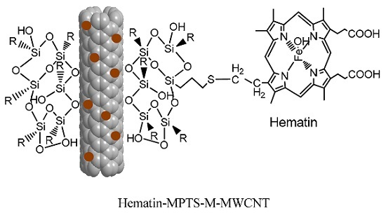
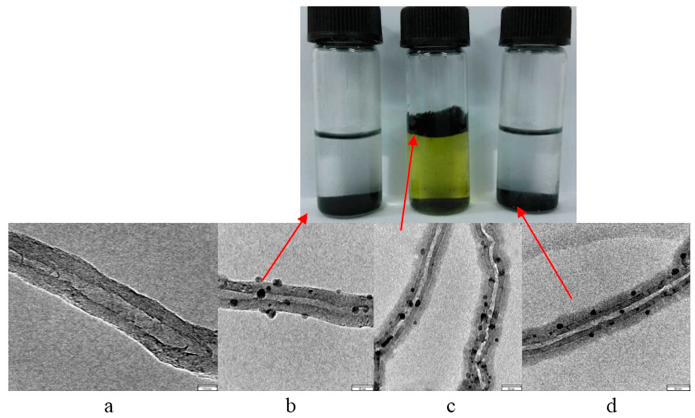
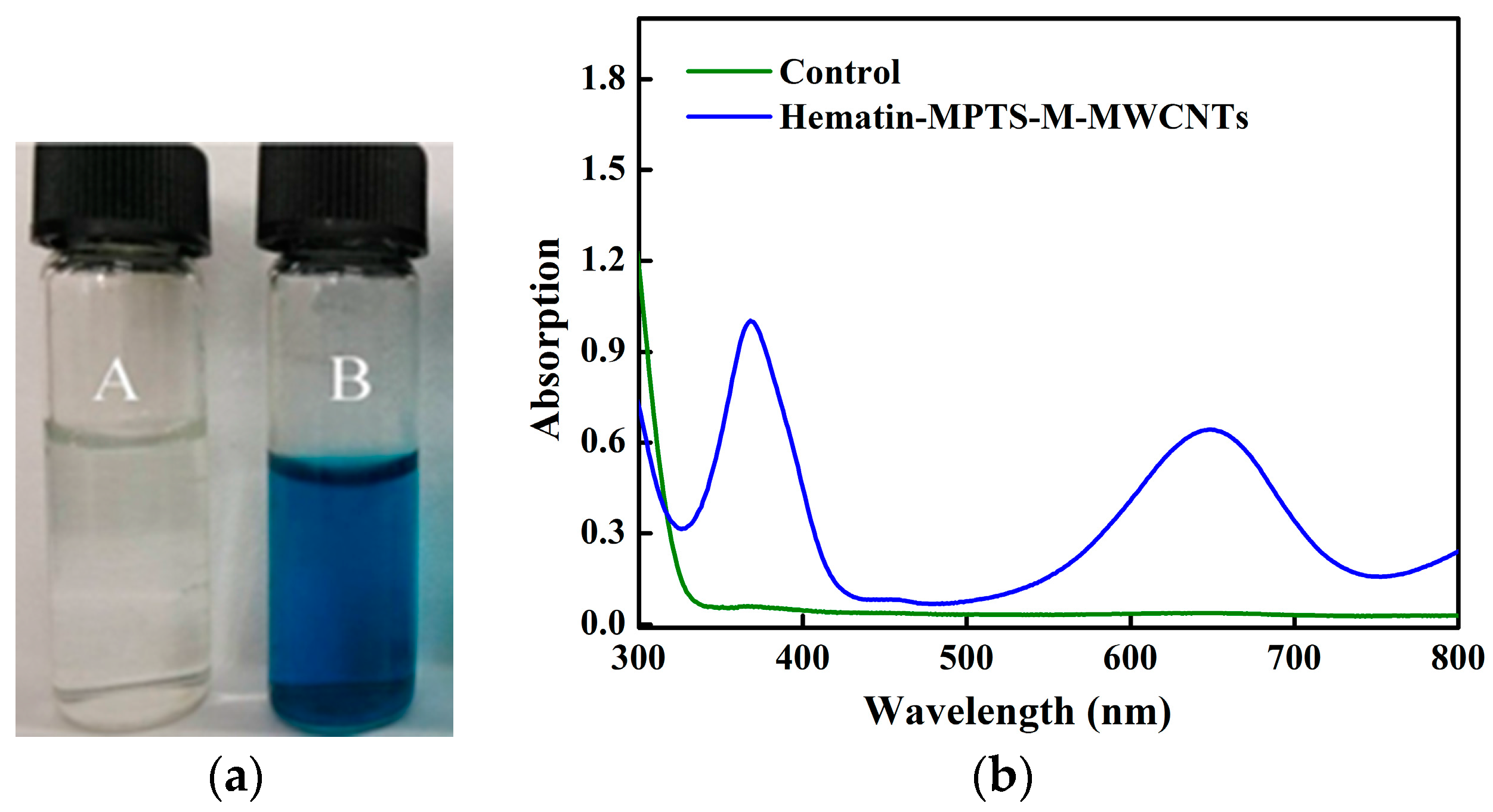
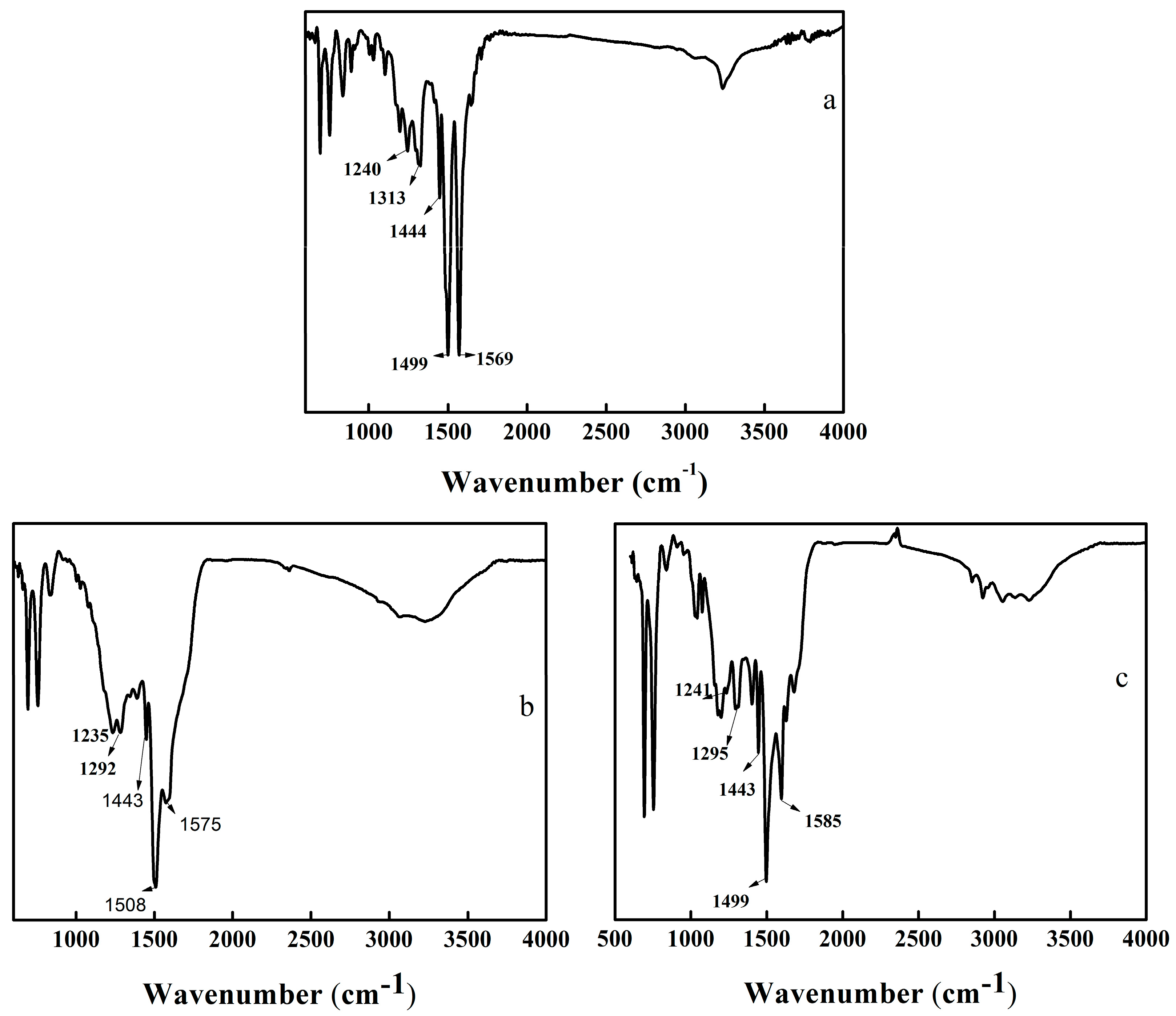
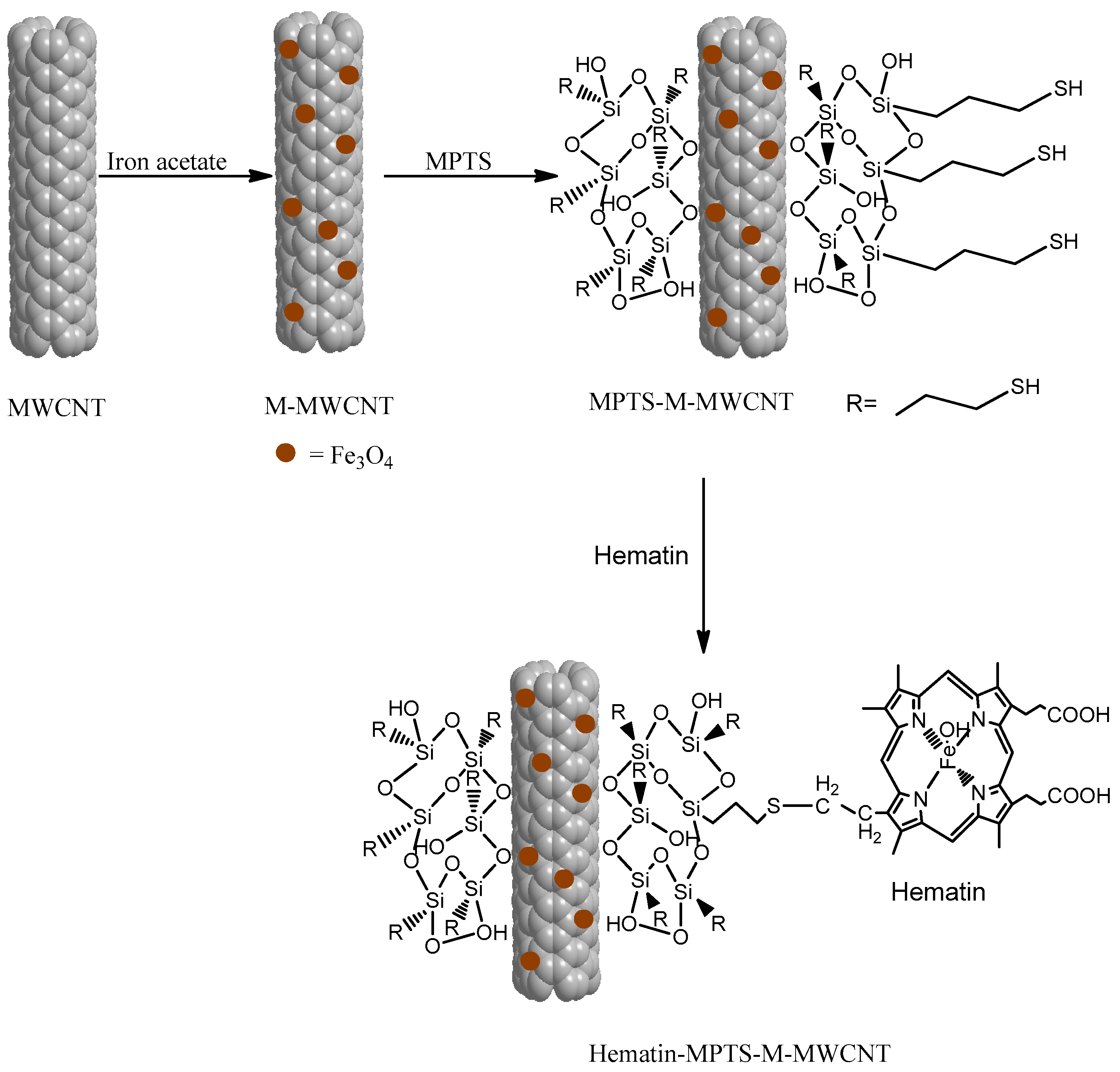
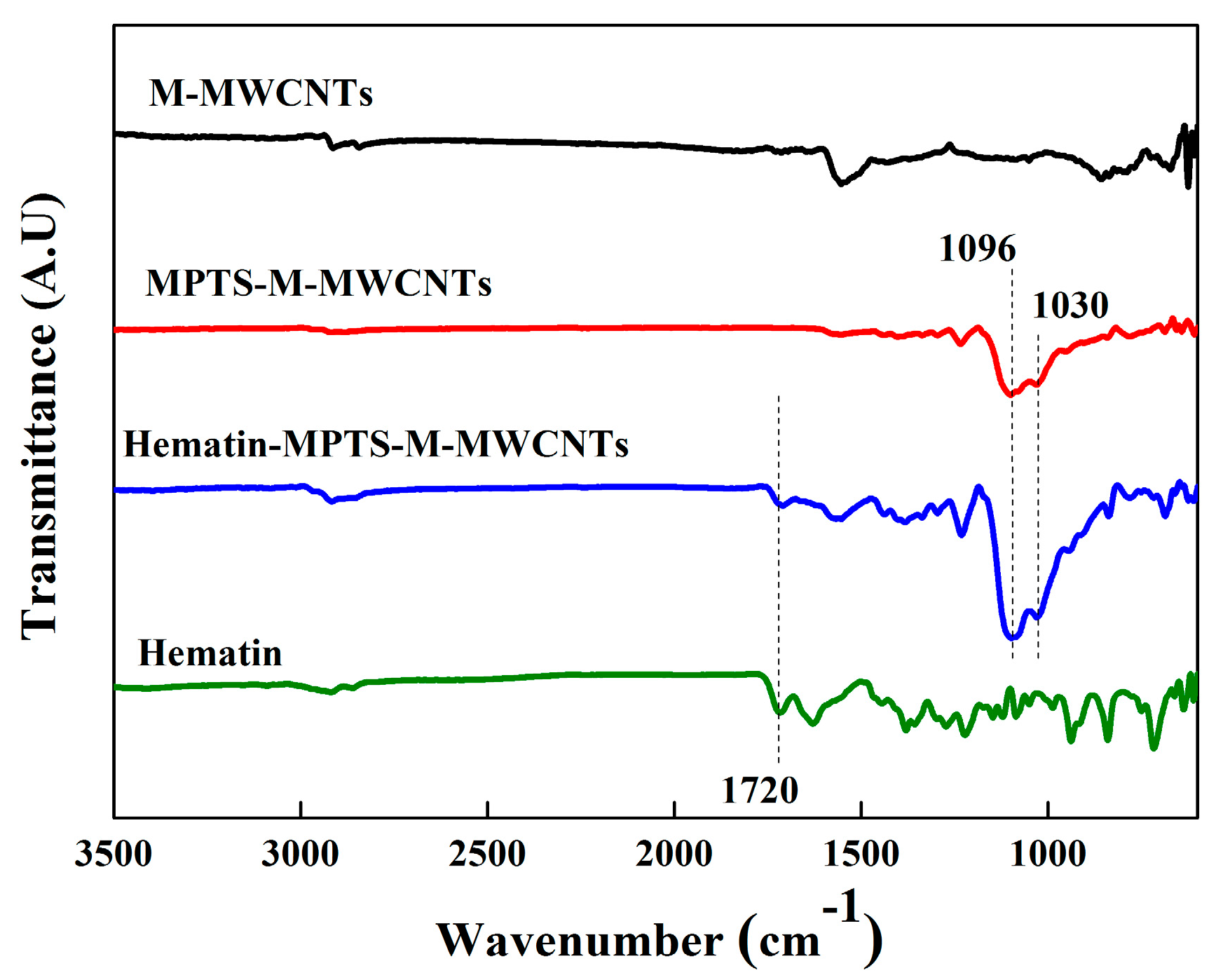
2.1. Grafting Hematin
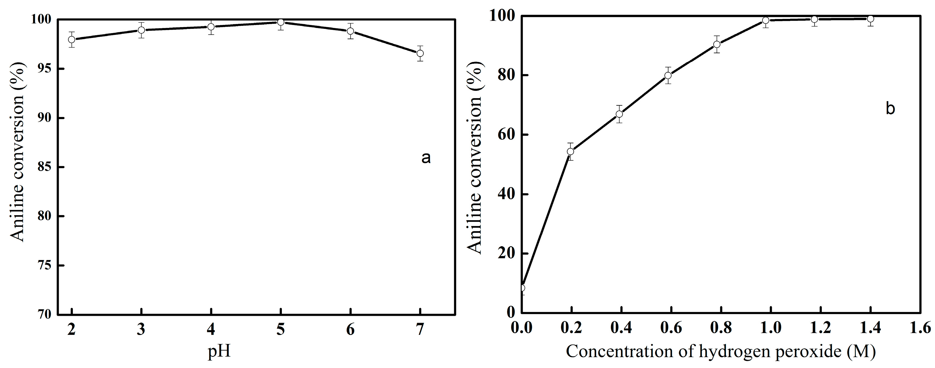
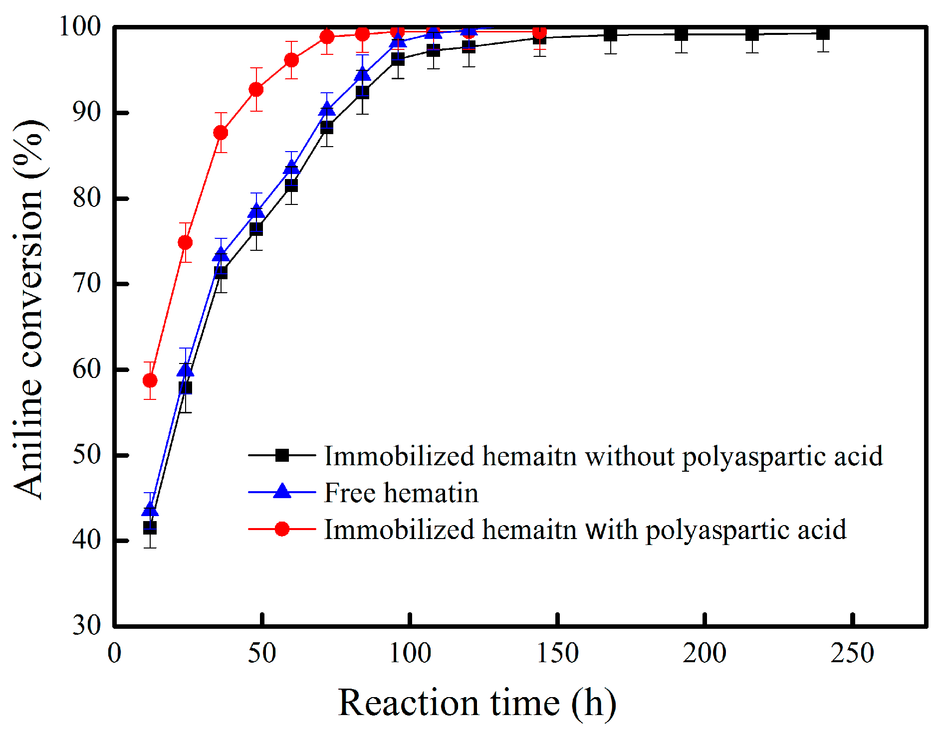
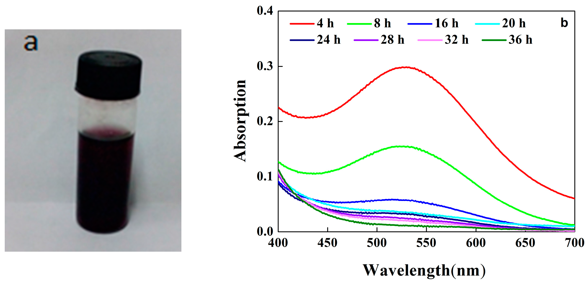
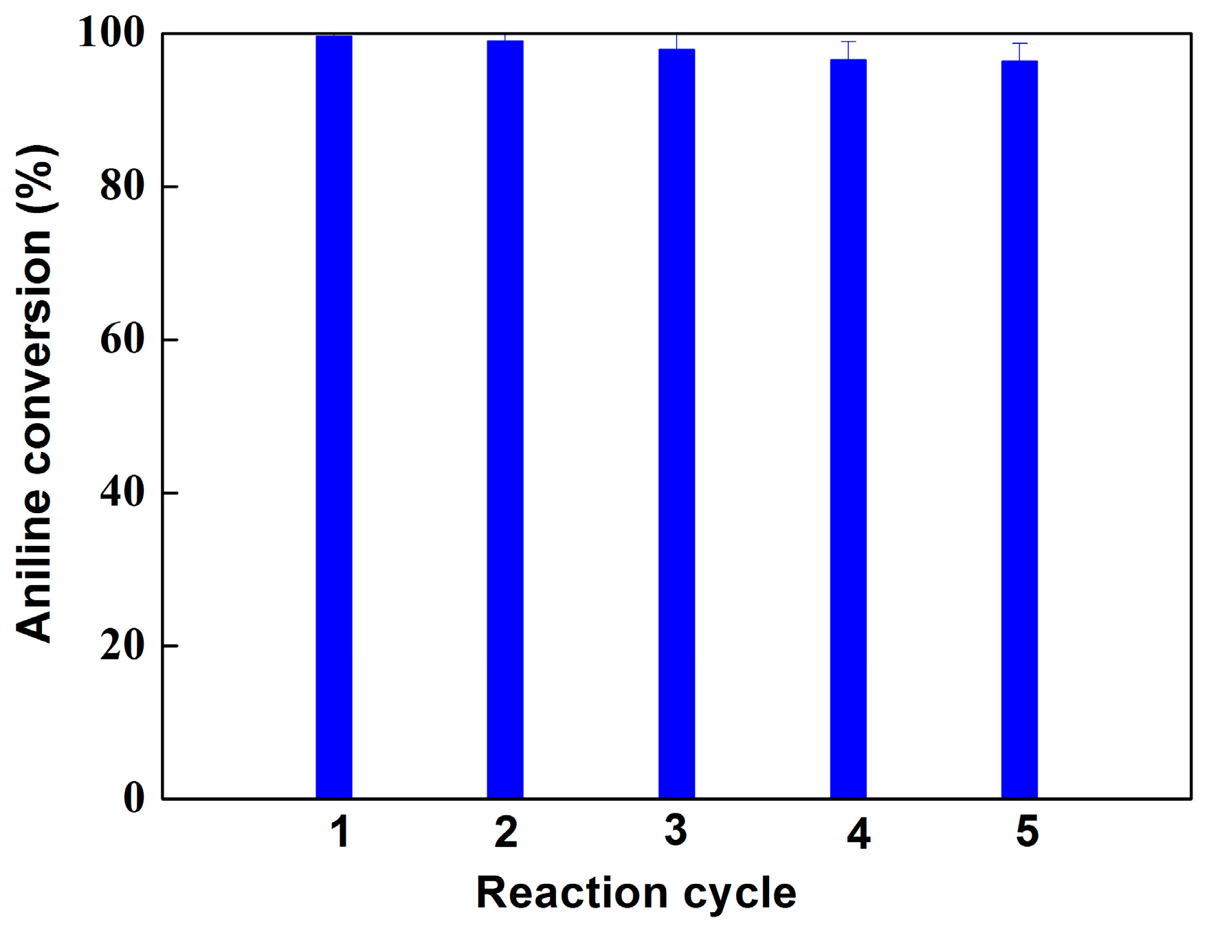
2.2. Oxidation of Aniline Catalyzed by Hematin-MPTS-M-MWCNTs
3. Experimental Section
3.1. Materials
3.2. Grafting Hematin
3.3. Oxidation of Aniline
3.4. Measurement of Optical Spectrum
4. Conclusions
Supplementary Materials
Acknowledgments
Author Contributions
Conflicts of Interest
References
- Gupta, V.K.; Nayak, A.; Agarwal, S. Performance evaluation and application of oxygen enriched waste rubber tire adsorbent for the removal of hazardous aniline derivatives from waste water. Chem. Eng. J. 2012, 203, 447–457. [Google Scholar] [CrossRef]
- Chen, H.; Zhuang, R.; Yao, J.; Wang, F.; Qian, Y.; Masakorala, K.; Cai, M.; Liu, H. Short-term effect of aniline on soil microbial activity: A combined study by isothermal microcalorimetry, glucose analysis, and enzyme assay techniques. Environ. Sci. Pollut. Res. 2014, 21, 674–683. [Google Scholar] [CrossRef] [PubMed]
- Wang, P.; Hua, Z.; Cai, Y.; Shen, X.; Li, Q.; Liu, X. Effects of hydrodynamic conditions on the sorption behaviors of aniline on sediment with coexistence of nitrobenzene. Environ. Sci. Pollut. Res. 2015, 22, 11595–11605. [Google Scholar] [CrossRef] [PubMed]
- Dvořák, L.; Lederer, T.; Jirků, V.; Masák, J.; Novák, L. Removal of aniline, cyanides and diphenylguanidine from industrial wastewater using a full-scale moving bed biofilm reactor. Process. Biochem. 2014, 49, 102–109. [Google Scholar] [CrossRef]
- Ersöz, G.; Atalay, S. Treatment of aniline by catalytic wet air oxidation: Comparative study over CuO/CeO2 and NiO/Al2O3. Environ. Manag. 2012, 113, 244–250. [Google Scholar] [CrossRef] [PubMed]
- An, F.; Feng, X.; Gao, B. Adsorption of aniline from aqueous solution using novel adsorbent PAM/SiO2. Chem. Eng. J. 2009, 151, 183–187. [Google Scholar] [CrossRef]
- László, K. Adsorption from aqueous phenol and aniline solutions on activated carbons with different surface chemistry. Colloid. Surf. A 2005, 265, 32–39. [Google Scholar] [CrossRef]
- Li, B.; Lei, Z.; Huang, Z. Surface-treated activated carbon for removal of aromatic compounds from water. Chem. Eng. Technol. 2009, 32, 763–770. [Google Scholar] [CrossRef]
- Zhou, Y.; Gu, X.; Zhang, R.; Lu, J. Removal of Aniline from Aqueous Solution using Pine Sawdust Modified with Citric Acid and β-Cyclodextrin. Ind. Eng. Chem. Res. 2014, 53, 887–894. [Google Scholar] [CrossRef]
- Hu, Q. Equilibrium and kinetics of aniline adsorption onto crosslinked sawdust-cyclodextrin polymers. RSC Adv. 2014, 347, 857–860. [Google Scholar] [CrossRef]
- An, F.; Feng, X.; Gao, B. Adsorption property and mechanism of composite adsorbent PMAA/SiO2 for aniline. J. Hazard. Mater. 2010, 178, 499–504. [Google Scholar] [CrossRef] [PubMed]
- Sánchez, L.; Peral, J.; Domènech, X. Aniline degradation by combined photocatalysis and ozonation. Appl. Catal. B Environ. 1998, 19, 59–65. [Google Scholar] [CrossRef]
- Jing, Z.; Yao, W.; Chao, Q.; Liu, L.; Lan, Y. Rapid degradation of aniline in aqueous solution by ozone in the presence of zero-valent zinc. Chemosphere 2015, 141, 258–264. [Google Scholar]
- Wang, L.; Barrington, S.; Kim, J.W. Biodegradation of pentyl amine and aniline from petrochemical wastewater. J. Environ. Manag. 2007, 83, 191–197. [Google Scholar] [CrossRef] [PubMed]
- Liu, J.; Guan, J.; Ming, L.; Kan, Q.; Li, Z. Hemoglobin immobilized with modified “fish-in-net” approach for the catalytic removal of aniline. J. Hazard. Mater. 2012, 217, 156–163. [Google Scholar] [CrossRef] [PubMed]
- Curvetto, N.R.; Figlas, D.; Brandolin, A.; Saidman, S.B.; Rueda, E.H.; Ferreira, M.L. Efficiency of enzymatic and non-enzymatic catalysts in the synthesis of insoluble polyphenol and conductive polyaniline in water. Biochem. Eng. J. 2006, 29, 191–203. [Google Scholar] [CrossRef]
- Guo, Z.; Hauser, N.; Moreno, A.; Ishikawa, T.; Walde, P. Aot vesicles as templates for the horseradish peroxidase-triggered polymerization of aniline. Soft Matter 2010, 7, 180–193. [Google Scholar] [CrossRef]
- Guo, Z.; Rüegger, H.; Kissner, R.; Ishikawa, T.; Willeke, M.; Walde, P. Vesicles as soft templates for the enzymatic polymerization of aniline. Langmuir 2009, 25, 11390–11405. [Google Scholar] [CrossRef] [PubMed]
- Adams, P.A.; Adams, C.; Berman, M.C.; Baldwin, D.A. H2O2- and alkyl hydroperoxide-supported para, hydroxylation of aniline by alkaline hematin. J. Inorg. Biochem. 1982, 17, 261–267. [Google Scholar] [CrossRef]
- Ambrosio, K.; Rueda, E.; Ferreira, M.L. Magnetite-supported hematin as a biomimetic of horseradish peroxidase in phenol removal by polymerization. Biocatal. Biotransform. 2009, 22, 35–44. [Google Scholar] [CrossRef]
- Tierrablanca, E.; Romero-García, J.; Roman, P.; Cruz-Silva, R. Biomimetic polymerization of aniline using hematin supported on halloysite nanotubes. Appl. Catal. A Gen. 2010, 381, 267–273. [Google Scholar] [CrossRef]
- Ellman, G.L. Tissue sulfhydryl groups. Arch. Biochem. Biophys. 1959, 82, 70–77. [Google Scholar] [CrossRef]
- Minier, M.; Salmain, M.; Yacoubi, N.; Barbes, L.; Méthivier, C.; Zanna, S.; Pradier, C. Covalent immobilization of lysozyme on stainless steel. Interface spectroscopic characterization and measurement of enzymatic activity. Toxicon 2005, 21, 5957–5965. [Google Scholar] [CrossRef] [PubMed]
- Silverstein, R.; Bassler, G.; Morrill, R. Spectrometric Identification of Organic Compounds; Wiley: New Jersey, NJ, USA, 1981. [Google Scholar]
- Josephy, P.D.; Eling, T.; Mason, R.P. The horseradish peroxidase-catalyzed oxidation of 3, 5, 3′, 5′-tetramethylbenzidine. Free radical and charge-transfer complex intermediates. J. Biol. Chem. 1982, 257, 3669–3675. [Google Scholar] [PubMed]
- Adams, P.A.; Adams, C.; Berman, M.C.; Lawrence, M.C. The nature of heme-aniline interactions during hemin-mediated oxygen activation and insertion reactions. J. Inorg. Biochem. 1984, 20, 291–297. [Google Scholar] [CrossRef]
- Trchová, M.; Šedenková, I.; Konyushenko, E.N.; Stejskal, J.; Holler, P.; Ciric-Marjanovic, G. Evolution of polyaniline nanotubes: The oxidation of aniline in water. J. Phys. Chem. B 2006, 110, 9461–9468. [Google Scholar] [CrossRef] [PubMed]
- Zujovic, Z.D.; Zhang, L.; Bowmaker, G.A.; Kilmartin, P.A.; Travas-Sejdic, J. Self-assembled, nanostructured aniline oxidation products: A structural investigation. Macromolecules 2008, 41, 3125–3135. [Google Scholar] [CrossRef]
- Sun, J.; Du, K.; Fu, L.; Gao, J.; Zhang, H.; Feng, W.; Ji, P. Sodium hexadecyl sulfate as an interfacial substance adjusting the adsorption of a protein on carbon nanotubes. ACS Appl. Mater. Interfaces 2014, 17, 15132–15139. [Google Scholar] [CrossRef] [PubMed]
- Tan, H.; Feng, W.; Ji, P. Lipase immobilized on magnetic multi-walled carbon nanotubes. Bioresour. Technol. 2012, 115, 172–176. [Google Scholar] [CrossRef] [PubMed]


© 2016 by the authors; licensee MDPI, Basel, Switzerland. This article is an open access article distributed under the terms and conditions of the Creative Commons Attribution (CC-BY) license (http://creativecommons.org/licenses/by/4.0/).
Share and Cite
Zheng, K.; Li, P.; Wu, H.; Du, M.; Ji, P. Specifically Grafting Hematin on MPTS-Coated Carbon Nanotubes for Catalyzing the Oxidation of Aniline. Catalysts 2016, 6, 123. https://doi.org/10.3390/catal6080123
Zheng K, Li P, Wu H, Du M, Ji P. Specifically Grafting Hematin on MPTS-Coated Carbon Nanotubes for Catalyzing the Oxidation of Aniline. Catalysts. 2016; 6(8):123. https://doi.org/10.3390/catal6080123
Chicago/Turabian StyleZheng, Kunkun, Peng Li, Hao Wu, Mengmeng Du, and Peijun Ji. 2016. "Specifically Grafting Hematin on MPTS-Coated Carbon Nanotubes for Catalyzing the Oxidation of Aniline" Catalysts 6, no. 8: 123. https://doi.org/10.3390/catal6080123
APA StyleZheng, K., Li, P., Wu, H., Du, M., & Ji, P. (2016). Specifically Grafting Hematin on MPTS-Coated Carbon Nanotubes for Catalyzing the Oxidation of Aniline. Catalysts, 6(8), 123. https://doi.org/10.3390/catal6080123