Article

Information-Driven Catalyst Design Based on High-Throughput Intrinsic Kinetics

Laboratory for Chemical Technology, Ghent University, Technologiepark 914, Ghent 9052, Belgium
*
Author to whom correspondence should be addressed.
Catalysts 2015, 5(4), 1948-1968; https://doi.org/10.3390/catal5041948
Submission received: 15 October 2015 / Revised: 30 October 2015 / Accepted: 4 November 2015 / Published: 16 November 2015
(This article belongs to the Special Issue High-Throughput Catalysts)

Abstract

:
A novel methodology is presented for more comprehensive catalyst development by maximizing the acquired information rather than relying on statistical methods or tedious, elaborate experimental testing. Two dedicated high-throughput kinetics (HTK) set-ups are employed to achieve this objective, i.e., a screening (HTK-S) and a mechanistic investigation one (HTK-MI). While the former aims at evaluating a wide range of candidate catalysts, a limited selection is more elaborately investigated in the latter one. It allows focusing on an in-depth mechanistic analysis of the reaction mechanism resulting in so called “kinetic” descriptors and on the effect of key catalysts properties, also denoted as “catalyst” descriptors, on the catalyst performance. Both types of descriptors are integrated into a (micro)kinetic model that allows a reliable extrapolation towards operating conditions and catalyst properties beyond those included in the high-throughput testing. A case study on ethanol conversion to hydrocarbons is employed to illustrate the concept behind this methodology. The methodology is believed to be particularly useful for potentially large-scale chemical reactions.

Graphical Abstract

1. Introduction

Catalyst development often relies on “trial and error” procedures in which laboratory scale performance is, implicitly, deemed to represent industrial scale operation. Despite many efforts to rationalize the development of catalytic material by using, among others, virtual catalyst screening [1], the “chemical experiment” remains a valuable and credible tool for novel catalyst development as it yields important information on catalyst activity, selectivity and long-term stability. Prior to the emergence of high-throughput technologies, catalyst development used to be constrained by the number that could be investigated within an available time frame or budget. At present, high-throughput experimentation has allowed overcoming this hurdle such that, instead, data management and interpretation have become the bottleneck [2,3].
The necessity of high-throughput experimentation was already demonstrated by Thomas Edison in 1878 who tested 1600 different materials for the incandescent lamp [4]. In catalysis research, the efforts of Mittasch and coworkers between 1909 and 1912 to improve Haber-Bosch ammonia synthesis, in which, originally, expensive osmium was used as catalyst, can be considered to be one of the first examples of high-throughput-like experimentation. In total, 2500 formulations were screened in 6500 experiments using a specifically designed small-scale, high pressure apparatus that allowed continuous testing by easily inserting and removing cartridges containing 2 g of catalyst sample [5]. Eventually, thirty of these reactors were operated simultaneously, which resulted in the selection of an inexpensive yet highly effective catalyst. Most commercial catalysts on the market today are just slight variations of the catalyst identified bafck in time, i.e., a magnetite promoted by K2O, CaO, SiO2, and Al2O3. Many other successful examples of high-throughput based material development have been reported [6]. Most efforts have been spent on accelerating material synthesis and testing [7,8,9] by optimization of the catalyst library using e.g., the split and pool method [10], Design of Experiments (DoE) [11] or an evolutionary algorithm [12]. Only few have tried to develop more comprehensive strategies for catalyst development [13,14].
The systematic measurement of chemical kinetics is often overlooked during catalyst development. Upon the acquisition of intrinsic kinetics, the chemical reaction rate is measured without being affected by any other phenomena such as mass or heat transport. Such kinetics quantify unequivocally the occurring elementary chemical phenomena and lead to an unprecedented understanding of the effect of catalyst properties on its activity, selectivity and stability. The implementation of high-throughput technologies for (intrinsic) kinetic studies of complex, multistep catalytic reactions has already been demonstrated for, among others, Fischer-Tropsch synthesis, partial oxidations, olefin polymerization, hydroformylation and hydroconversion [15,16,17,18].
Catalyst development challenges will continue requiring attention due to the variations in feedstock, e.g., from fossil to renewable, but also from conventional fossil to alternative fossil fuels. Compared to the large scale of a conventional refinery, in the case of renewable feeds, the development various novel processes such as glycerol hydrogenolysis and cellulose aminolysis are expected. This will result in an increasing importance of liquid phase processes [19] and is expected to involve a transition from a limited number of large scale production facilities towards larger numbers of medium scale ones located near the biomass production facility.
In this work, an efficient catalyst development methodology based on fundamental kinetic modeling, denoted as information-driven catalyst design, is presented. The initial objective is not to maximize the catalyst performance but rather the information that can be acquired by high-throughput experimentation. In a second step, relying on (micro)kinetic modeling, the methodology is supposed to lead more adequately to superior catalyst performance compared to other techniques. The methodology is believed to be particularly suited to “large-scale” reactions referring to the actual scale of a single plant or the number of (smaller) plants existing for this reaction. This methodology will be illustrated using ethanol conversion to hydrocarbons as model reaction.

2. Catalyst Design Methodologies

Several strategies for catalyst design can be found in literature [20] and can be classified into two categories: so-called statistics- and performance-driven catalyst design (Figure 1a,b). The alternative methodology proposed in this work is presented in Figure 1c. The differences between these methodologies are more elaborately discussed in the paragraphs below.

2.1. Statistics-Driven Catalyst Design

Having defined the catalyst characteristics to be optimized, the boundaries of the domain in which they will be varied need to be determined. An experimental design can be subsequently followed to actually determine the “best” catalyst as shown in Figure 1a. The optimization can occur according to the “one-variable-at-a-time” principle [21,22], however more advanced, statistical designs can also be implemented.
A full factorial design may be applied to cover a broad range of experimental conditions. The drawback from such a design is the gargantuan number of experiments that needs to be performed, e.g., for only a 2-level, 7-factor design, a total of 128 experiments needs to be performed. The use of fractional factorial designs conveniently reduces the number of experiments. Several classical symmetrical designs can applied for this, such as circumscribed, inscribed and face centered central composite designs or Box-Behnken designs [23].
The relation established between catalyst characteristics (factors, xi) and performance (y) is typically of a linear nature in the parameters (bi) while quadratic and interaction terms for the factors are generally also considered:
y = b 0 + b 1 x 1 + b 2 x 2 + b 3 x 1 2 + b 4 x 2 2 + b 5 x 1 x 2
Such empirical linear relations lack the fundamental detail governing the catalyst performance. It is evident that the use of such relationships is, at most, suited for interpolation purposes and will not lead to reliable extrapolations, not to mention their irrelevance for simulating catalyst behavior at different operating conditions or with alternative feeds. Although among a set of relatively poorly performing catalysts, a significant improvement may be achieved, the lack of fundamental character in the developed relationships, can reasonably be expected to result in a relatively straightforward selection of a sub-optimal catalyst, e.g., pronounced non-linearities in catalyst activity as induced by the Arrhenius or van ‘t Hoff relationships are not adequately captured by such empirical models. In addition, non-linear interaction effects will only be poorly described.
Figure 1. Different methodologies in catalyst design: (a) statistics-driven catalyst design; (b) performance-driven catalyst design; and (c) information-driven catalyst design. Catalyst performance is plotted on the y-axis and mechanistic information on the x-axis. The grid below the graphs conceptualizes a corresponding two-dimensional optimization study where x1 and x2 are two factors influencing catalyst performance. Color code: khaki, screening; red, in depth study; and blue, final selection and validation.
Catalysts 05 01948 g001

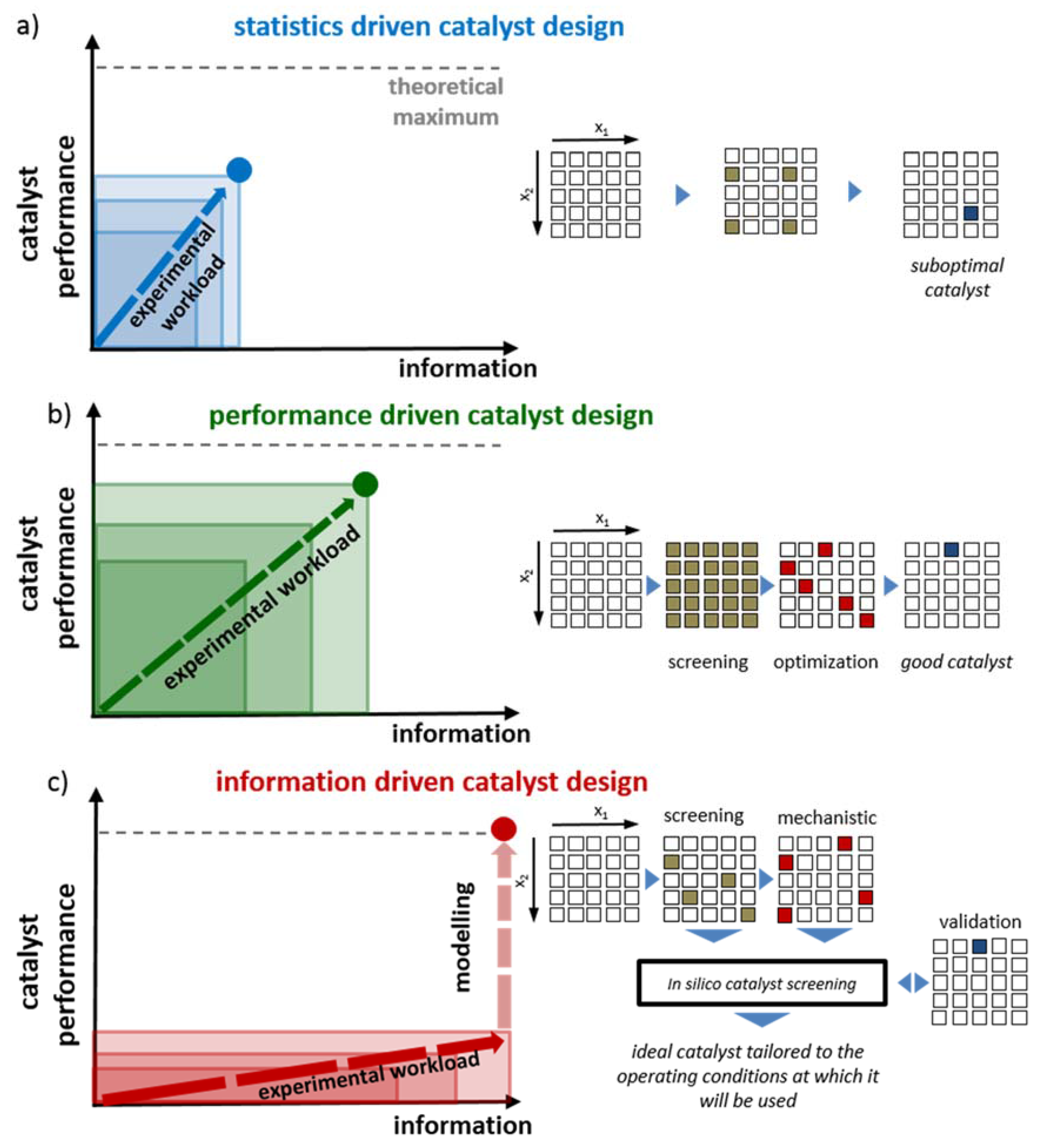
2.2. Performance-Driven Catalyst Design

The most experimentally intensive methodology, i.e., the so-called performance-driven catalyst design, is depicted in Figure 1b. In contrast to the single-stage development of the statistics-driven catalyst design, performance-driven catalyst design typically distinguishes between two development stages, i.e., a catalyst screening and a catalyst optimization stage [6,16,24]. During the catalyst screening stage, a wide variety of catalyst formulations are prepared, kinetically investigated and ranked based on activity, selectivity and stability performance at a single set of operating conditions. An extensive catalyst screening study is required before going into an advanced catalyst development stage. In the optimization stage, the potentially interesting catalysts from the first stage are tested on a more quantitative basis and subject to more prolonged testing. The bottleneck for this methodology is situated in the synthesis and testing of large numbers of catalysts as well as in the relevance of the acquired data for scale-up purposes.

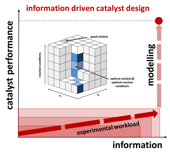
2.3. Information-Driven Catalyst Design

Information-driven catalyst design, as shown in Figure 1c, overcomes the drawbacks of the previously described methods. Initial catalyst screening is performed to determine which catalysts will allow retrieving a maximum amount of information. The corresponding catalyst selection is based on a preliminary assessment of catalyst property effects on their activity. The selected catalysts will not necessarily be the most active or selective ones, however as mentioned before, they should be the ones which will allow acquiring the most detailed mechanistic information.
This information is acquired in the second stage of the information-driven catalyst design methodology. Aiming at a better understating of the underlying reaction mechanism, information on the possible intermediates and by-products is obtained as well as on the effect of temperature and pressure on the catalyst performance. The information obtained in both the catalyst screening and kinetic testing, can be combined as input for microkinetic model development. The combination of an in-depth study on a well-selected catalyst and a more explorative study of the catalyst descriptors on a limited selection of catalysts, complemented by the initial screening results yields the desired kinetic and catalyst descriptors for the microkinetic model. Whereas the former capture the reactive properties, such as activity and selectivity, most often in terms of activation energies and pre-exponential factors, the latter specifically account for the effect of the catalyst properties on their performance. The catalyst descriptors constitute its fingerprint, i.e., a unique identifier which can be translated into a specific performance thanks to the microkinetic model [25].
The constructed microkinetic model is used in an in silico screening of alternative catalyst formulations. It also eliminates the need for traditional catalyst comparison methods such as the light-off temperature, i.e., temperature at 50% conversion or an apparent activation energy and pre-exponential factor [10]. Due to the fundamental character of the microkinetic model, the virtual screening allows reliable extrapolations beyond the operating conditions and catalyst properties contained in the dataset [26,27]. Finally, the performance of the novel catalyst formulation is compared to the virtual screening results in the validation step.
By implementation of these models in an adequate reactor model accounting for transport phenomena [28,29], specific reactor configurations such as a riser reactor [30] or a slurry-bubble column [31] and catalyst deactivation [32], reliable, industrially relevant simulations can be made with these models. This also comprises the extension from model compound behavior, as typically measured at the laboratory scale, to realistic feeds [25,33]. This methodology may not only lead to successful process scale-up but can also result in adequate reactor down scaling for the development of microreactors [34]. As the observed effects are incorporated on a fundamental level, this methodology allows limiting the number of experiments while still being able to extrapolate towards other operating conditions.
Both experimental stages, i.e., screening and mechanistic investigation, each require a dedicated, experimental high-throughput kinetics set-up. The high-throughput kinetics screening (HTK-S) set-up comprises a comparatively large number of parallel reactors with a limited reactor volume operating at identical conditions. Low catalyst masses are required in this set-up since this enables the evaluation of advanced, difficult-to-synthesize catalytic materials. The high-throughput kinetics mechanistic investigation (HTK-MI) set-up contains a more limited number of reactors in which operating conditions can be more independently varied such that a systematic exploration of the intrinsic kinetics in a whole range of operating conditions is possible within a limited time frame. The required amount of catalyst in this stage is about one order of magnitude higher such that the scale-up of the catalyst synthesis method can also be validated. The larger scale of the HTK-MI set-up also provides an opportunity for temperature measurement inside the reactor, helping to experimentally ensure the intrinsic kinetics character of the acquired data, see Section 3.
The main prerequisite for extrapolating towards other operating conditions and proper assessment of catalyst properties is the measurement of intrinsic kinetics. Generally, the most frequently encountered lab scale reactor for kinetic measurement is a fixed bed reactor which can either be operated in a differential or an integral regime since it is simple, inexpensive, applicable for both gas, liquid as well as three phase operation and deactivation can be observed immediately when pursuing steady-state conditions [16]. Additionally, in order not to complicate the construction of the microkinetic models, an ideal flow pattern in the reactor is strived for, i.e., ideal plug flow in the fixed bed reactor.
It is vital to improve the data acquisition efficiency with increasing number of reactors. Depending on the experimental stage, i.e., screening or mechanistic investigation, this can either be achieved by respectively analysis equipment diversification or duplication. Diversification leads to a more flexible analysis section, e.g., multiple gas chromatographs in which complementary columns and/or detectors are present. This is often used for catalyst screening due to large variety of catalysts tested, which potentially leads to a diverse product spectrum. Duplicating the analysis equipment is quite straightforward and allows timely data acquisition from a well-selected catalyst tested at a broad range of reaction conditions, i.e., during the mechanistic investigation.
The analysis equipment type typically depends on the reaction investigated. In the case where only a limited number of products is involved in the reaction, a spectroscopic method may be preferred due to its fast analysis, i.e., ms time range. Even mass spectrometry can be applied but has limited quantitative capabilities. When the individual determination of all products is important, chromatographic techniques are typically used.

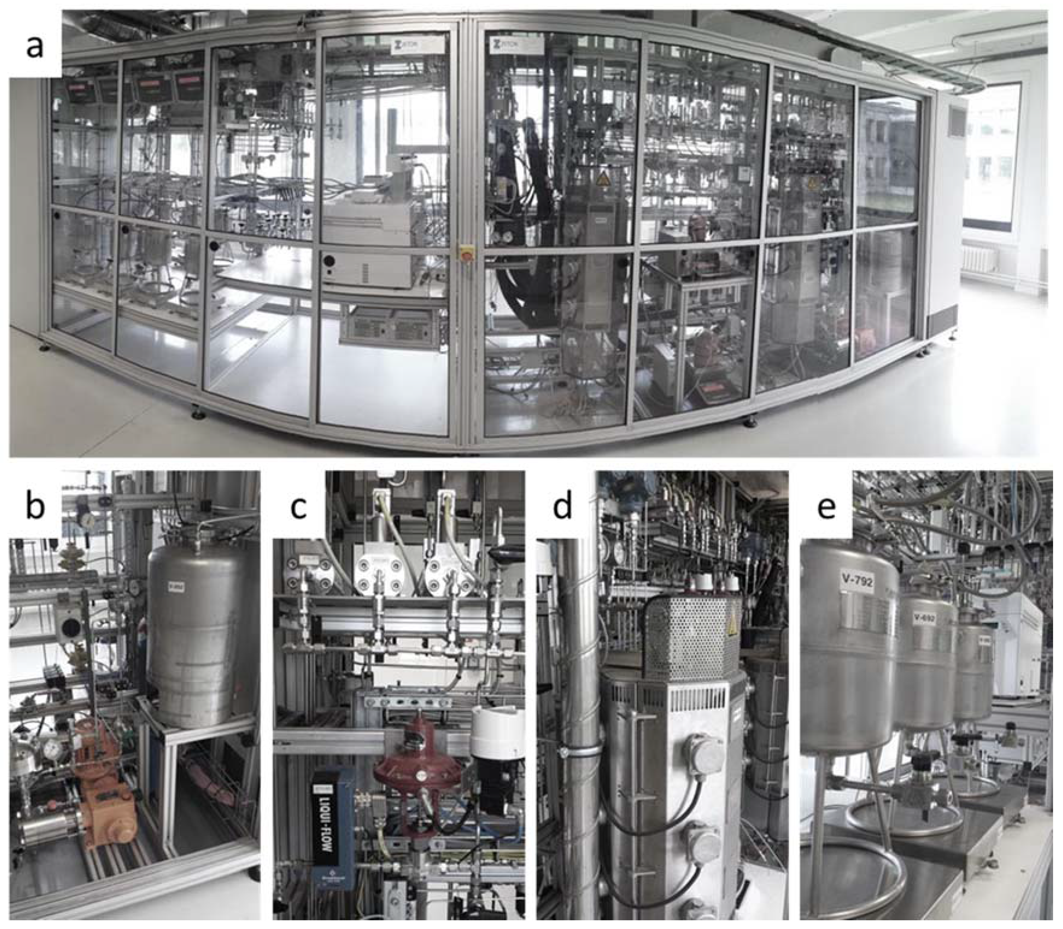
3. High-Throughput Kinetics Information Acquisition

Two complementary high-throughput kinetics (HTK) set-ups are available at the Laboratory for Chemical Technology at Ghent University, i.e., a high-throughput kinetics screening set-up (HTK-S) and high-throughput kinetics mechanistic investigation set-up (HTK-MI). They are specifically designed to achieve the goals put forward in the information-driven catalyst design methodology, i.e., catalyst screening and mechanistic investigation while providing reliable intrinsic kinetic data for microkinetic model construction. Table 1 compiles the most relevant features of these set-ups while a schematic representation of these set-ups is given in Figure 2.
Table 1. Features of and operating conditions used in the set-ups for Information-driven catalyst design.
Feature or Operating ConditionHigh-Throughput Kinetics Screening (HTK-S) High-Throughput Kinetics Mechanistic Investigation (HTK-MI)
number of reactors168
number of heating blocks44
reactor typeTubularTubular
reactor internal diameter did (10−3 m)2.111.0
reactor length L (m)0.80.9
feed flow rate controlper reactor blockper reactor
operating temperature range Tmin, Tmax (K)323–773 (SS) 323–1273 (Quartz)323–923
operating pressure range pmin, pmax (105 Pa)1–100 (SS) 1–3 (Quartz)1–200
catalyst mass W (10−3 kg)0.05–0.20.5–10
Figure 2. Schematic representation of one reactor block highlighting the differences between (a) HTK-S and (b) HTK-MI, where A corresponds to the reactors, B to the gas/liquid separators and C the liquid waste vessels.
Catalysts 05 01948 g002

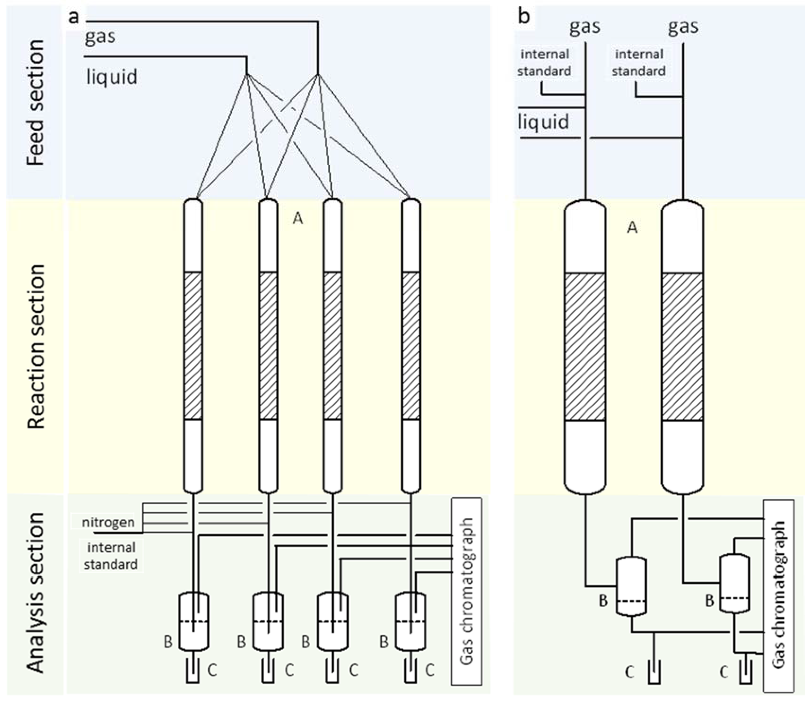
3.1. Screening (HTK-S)

The main goal of the HTK-S set-up is the fast parallel screening of a large variety and, hence, number of catalysts. Both simple and complex reaction networks can be dealt with. This set-up corresponds to the screening step, as shown in Figure 1c. During its design and construction by Integrated Lab Solutions [35], maximum flexibility was ensured with respect to different reaction types and catalysts. This set-up contains 16 parallel tubular reactors (i.d. = 2.1 mm), which are grouped four per heating block. The user can choose between stainless steel and quartz reactor tubes, depending on the target reaction. An overview and more detailed pictures of the HTK-S set-up are given in Figure 3.
Figure 3. HTK-S set-up pictures: (a) front view; (b) gas (top) and liquid (bottom) feed section; (c) reactor heating blocks; (d) heated gas and liquid sampling section; and (e) analysis section.
Catalysts 05 01948 g003

3.1.1. Feed Section

Three different gases are connected to the set-up for experiments with one Bronkhorst El-Flow thermal mass flow controller for each gas per reactor block (Figure 3b): An inert gas, e.g., He (flow rate range: 1–50 NL·h−1), a reducing gas, e.g. H2 (flow rate range: 1–50 NL·h−1) and an oxidizing gas, e.g., O2, (flow rate range: 1–25 NL·h−1). Vary-P controllers are implemented ensuring a flow rate independent of the feed bottle pressure. The liquid is pressurized using a Lab Alliance 12-6 dual piston pump (Figure 3b). The liquid flow rate per reactor is controlled using a Coriolis Mass Flow Controller, ensuring a flow rate independent of the liquid feed type (1–50 g·h−1).

3.1.2. Reaction Section

As indicated already above, the reaction section consists of four reactor blocks, of which two are shown in Figure 3c. The four reactors contained in a reactor block share a single feed line. The feed flow through this line is equally distributed over all four reactors in the block making use of capillaries upfront of each of the reactors. These capillaries ensure a pressure drop sufficiently exceeding that over the catalyst bed such that the flow rate is distributed evenly. It is evident that the dimensioning of this capillary distribution system has to be very precise. Its dimensions for gas and liquid were as follows: Lcap,g = 1.00 m; dcap,g = 75 µm and Lcap,l = 0.75 m; dcap,l = 75 µm.
Each reactor block is heated by an electrical oven (Figure 3c), which is constructed of silicon carbide (SiC) because of its high thermal conductivity. The electrical heating elements are at the outside of the SiC block in which holes were drilled for the reactors. In each block, two thermocouples are present: one located near the heating element measuring the oven temperature To, and one in the reactor block center measuring the reactor temperature, i.e., TM (Figure 4a,b). The reactor pressure is regulated by using an El-press pressure controller (Bronkhorst).
Figure 4. (a) Schematic representation of a reactor block of the HTK-S set-up (1. insulation, 2. Electrical heating, 3. SiC, 4. reactor well, TC: central thermocouple; TO: thermocouple located near the heating elements) and (b) axial temperature profile measured in the absence of reaction (setpoint: 203 K); isothermal zone indicated in green (ΔT < 1 K).
Catalysts 05 01948 g004
In principle, the best practice would be to measure the catalyst bed temperature directly to verify the actual reaction temperature. Due to the small reactor diameter, i.e., 2.1 mm, it is impossible to insert an internal thermocouple to measure this local temperature. Therefore, the internal reactor temperature was verified via separate, non-reactive measurements. The temperature in the reactor was measured in the absence of reaction, feed flow rates and a catalyst bed. A thermocouple was placed in the reactor from the top and a temperature was set for the oven. By gradually sliding the thermocouple through the reactor, a temperature profile could be obtained (Figure 4b). An isothermal zone (ΔT <1 K) of 0.30 m was determined as indicated in the figure. Via the use of adequate correlations [36], it was determined that even in the presence of highly exo- and endothermic reactions ( | Δ H r | > 1000 kJ · mol - 1 ) and at reaction rates sufficiently low to eliminate transport limitations at the scale of the catalyst particle, no significant temperature profiles will develop in this reactor configuration.
Easy reactor handling is ensured by the utilization of a double O-ring sealing which is able to maintain pressures up to 100 bar. By virtue of these sealings, the time required to remove or load the reactors is significantly reduced compared to using conventional, metal connections. Particular attention needs to be paid to the loading of the catalyst bed, including inert material, to avoid segregation in these small diameter reactors. The generally accepted procedure [37] to pack beds of shaped catalysts diluted with fine powders with intermediate tapping or vibrating, does not work for fine powder beds. As suggested by van Herk et al. [38], premixing the catalyst particles using a tumbler-type mixing to ensure free flow of fluidized swirling power before loading into the reactor is required for a small diameter reactor. A steep angle funnel made of a smooth material, e.g., stainless steel, is used to load the catalyst-inert mixture in small batches to reduce the possibility of segregation. A densification procedure with intense vibration and/or tapping has to be performed before introducing the reactor in the reactor oven. The catalyst-inert mixture can easily be removed from the reactor and can be facilitated by tapping. The reactor is subsequently cleaned with ethanol or another solvent. If coking on the reactor wall occurs, the reactor needs to be treated at elevated temperature under an oxygen rich atmosphere to burn any residuals.

3.1.3. Analysis Section

Keeping the whole product spectrum in the gas phase is advantageous since it allows a fast and easy analysis. The presence of a liquid phase would require liquid collection time, additional sampling and more complex data treatment. Therefore, all tubing downstream of the reactor is mounted inside a hot air convection oven (Figure 3d). The maximum oven temperature is 473 K, such that heavy product condensation is minimized. The possible introduction of a nitrogen flow at the reactor outlet allows decreasing the heavy product partial pressures. The gas phase effluent of each reactor can be sampled by using one of the two ten-port selection valves, each of them being connected to eight reactors and a calibration or dilution gas. In order to quantify the effluent flow rate and to verify the mass and elemental balances, an internal standard is introduced downstream of the reactor before sampling.
Since renewable feedstocks are receiving more and more attention, only gas phase analytical equipment was considered not to be sufficient. For example, the decomposition temperature of sucrose is much lower than its vaporization temperature, even at decreased pressures. Therefore, gas-liquid separators are installed that can be operated in a temperature range from 293 to 473 K. The gas-liquid separators are mounted near the convection oven and are insulated to prevent cold spots. A three-way valve is present which is directly connected to the reactor effluent and fills up a dead end-liquid collection tube. When sufficiently filled, the valve is switched and the expelled liquid is collected in a glass vial. These glass vials are located on a holder plate fixed to an autosampler.
The analysis section comprises three gas chromatographs, i.e., two Detailed Hydrocarbon Analyzers (DHA, Thermo Fisher Scientific), each analyzing the effluent of two reactor blocks, and one Refinery Gas Analyzer (RGA, Thermo Fisher Scientific), which is common for all four reactor blocks. These GCs are shown in Figure 3e. The RGA comprises a Hayesep N column for separation of CO2, C2H4, C2H6, and C2H2; molsieve 5A for O2, N2, CH4, and CO; and a Carbosphere for H2. The analysis of these gases is performed on two thermal conductivity detectors (TCD). Hydrocarbon separation up to C4 hydrocarbon isomers is performed using an Al2O3/KCl column and a flame ionization detector (FID).
While the RGA can only sample on-line, both on- and off-line injections can be performed on the DHA. Both DHA GC are equipped with a PONA column (Paraffins, Olefins, Naphthenes and Aromatics) and an additional, more dedicated column, e.g., to separate oxygenates or amines. The presence of both a flame-ionization detector (FID) and nitrogen phosphorous detector (NPD) allows for a versatile and simultaneous effluent stream analysis. The DHA analysis time for a PONA analysis typically requires 1 h, depending on the product spectrum that needs to be analyzed. The RGA analysis time is limited to 17 min and is able to detect a product spectrum from permanent gasses up to C5 hydrocarbons, allowing for a semi-continuous screening of the catalyst activity.

3.2. Mechanistic Investigation (HTK-MI)

After the screening stage, a benchmark catalyst is selected, on which an extensive experimental study is performed complemented by a few additional catalysts for the catalyst descriptor determination. This is depicted as the mechanistic investigation step, as shown in Figure 1c. This mechanistic investigation is performed in the HTK-MI set-up. Its design by Zeton [39] contains eight parallel tubular reactors (i.d. = 11 mm), which are grouped two per oven. The temperature can range up to 923 K and the pressure can be elevated up to 200 bar. Due to the larger dimensions of the reactors compared to the HTK-S set-up reactors, no specific caution should be taken with respect to catalyst bed mixing. An overview and more detailed pictures of the HTK-MI investigation set-up are given in Figure 5.

3.2.1. Feed Section

The set-up has one plunger-diaphragm dosing pump (Figure 5b, which pressurizes and feeds a liquid reactant to all the liquid mass flow controllers (Liquid-Flow, Bronkhorst) (Figure 5c, bottom). A pulsation damper helps to ensure a constant flow rate from the pump. The same feed type is sent to all eight reactors. The feed flow rate, however, is set individually per reactor. Bronkhorst El-Flow gas mass flow controllers, with a flow rate ranging up to either 10 NL·h−1, 100 NL·h−1 or 1000 NL·h−1 are installed (Figure 5c, top). One of the three gas feed flows is used as internal standard in order to quantify of the effluent flow rate and to verify the mass and elemental balances.
Figure 5. HTK-MI set-up pictures: (a) front view; (b) liquid pump section; (c) gas (top) and liquid (bottom) feed section; (d) reactor blocks; and (e) liquid waste collection.
Catalysts 05 01948 g005

3.2.2. Reaction Section

Each reactor is paired with a second one in a reactor block (Figure 5d) and is made of stainless steel (AISI 316 cold worked steel) with a length of 0.9 m and an internal diameter of 11 mm. An internal three-point thermocouple of 3 mm diameter allows to measure and control the actual temperature of the catalyst bed. An additional thermocouple is placed at the outer reactor wall. The temperature can be controlled either via the inner or outer thermocouple. Temperature control using the external thermocouple is recommended since it leads to a lower dead time. The three-point character of the used thermocouple allows ensuring a uniform temperature profile throughout the reactor axial direction. The reactor pressure is maintained via back-pressure control.

3.2.3. Analysis Section

The reactor effluent is initially maintained at sufficiently high temperature via IR-heating at the reactor outlet and consequently via heat tracing up to the backpressure regulator. This avoids heavy product condensation when working at gas phase conditions in the reactor. Downstream of the back pressure regulator, the effluent enters a flash drum operated at ambient temperature. The flash drum is used to separate the gas from liquid at ambient temperature in the effluent, if any. The gases continue to the gas analysis section which is also heat traced to avoid condensation of heavy components in the gas effluent. A multiport selection valve (one inlet for each reactor, one for calibration purposes and one outlet to the analysis equipment) allows selecting the effluent to be sampled. Downstream of the multiport selection valve, the gas stream is sent directly to a micro-GC (μGC). The μGC is a compact device which contains four parallel columns (molesieve column: separation of permanent gases and methane, PLOTU column: separation of C2 and C3 hydrocarbon, Alumina column: C3 and C4 hydrocarbons and OV-1 column: isomer separation of C4 to C6 hydrocarbons) with each a TCD detector. This is allows a very fast analysis, i.e., less than five minutes, and the detection of a product range from permanent gasses to light hydrocarbons up to C6. The liquid continues through the set-up by gravity and passes through a sampling device where a GC PAL robotic arm can take a liquid sample to be injected in one of the online GCs. Two GCs (Agilent Technologies 6850 series II network GC system) are available in the set-up for the analysis of the liquid phase reactor effluent and are equipped with a flame ionization detector (FID) to perform a PONA analysis. If required, the gas effluent can also be analyzed on these GCs. The liquids subsequently continue to the liquid waste storage tanks (Figure 5e). These tanks are placed on an electronic weighing scale with an accuracy of 0.5 g, which allows mass balance verification.

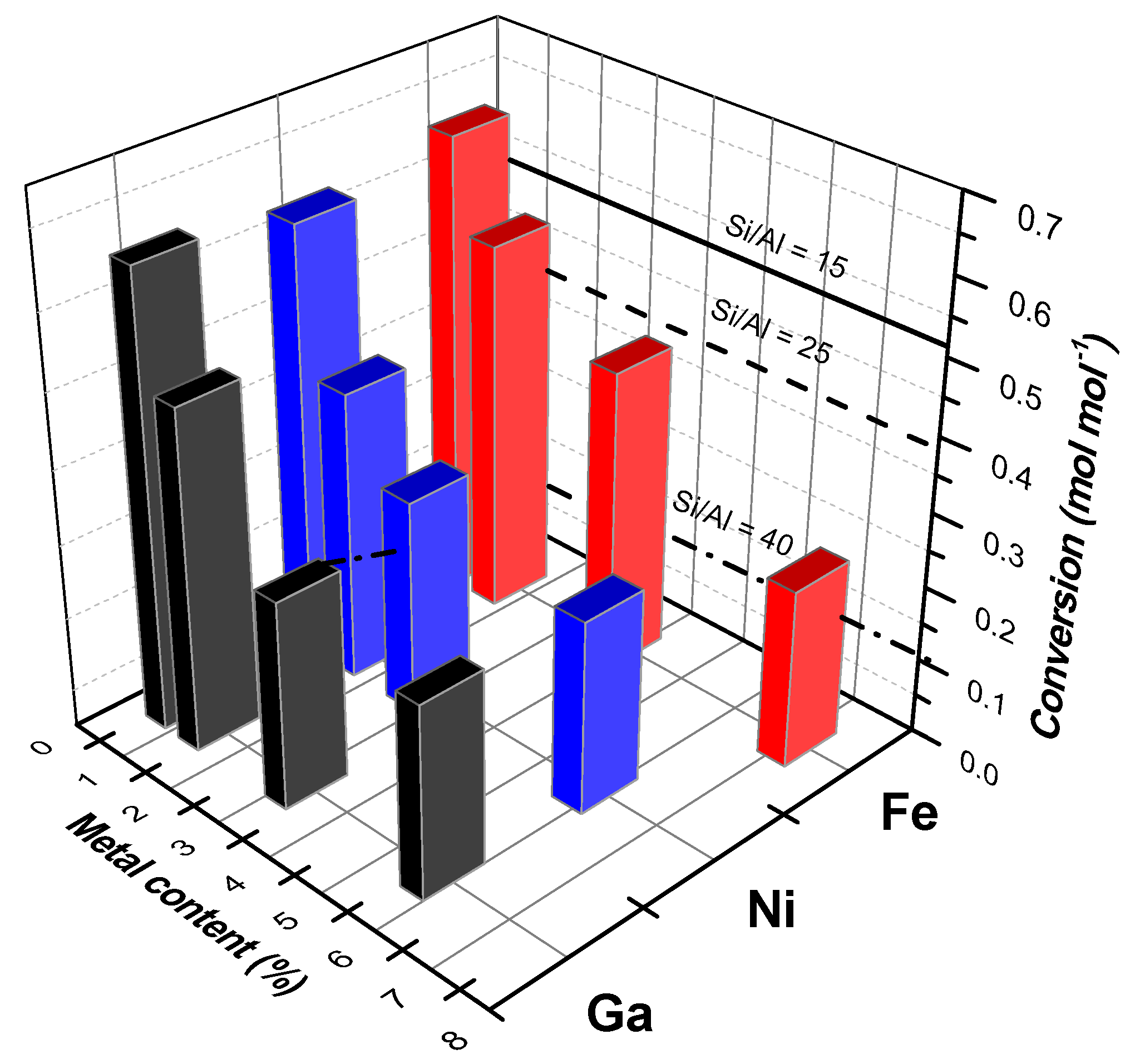
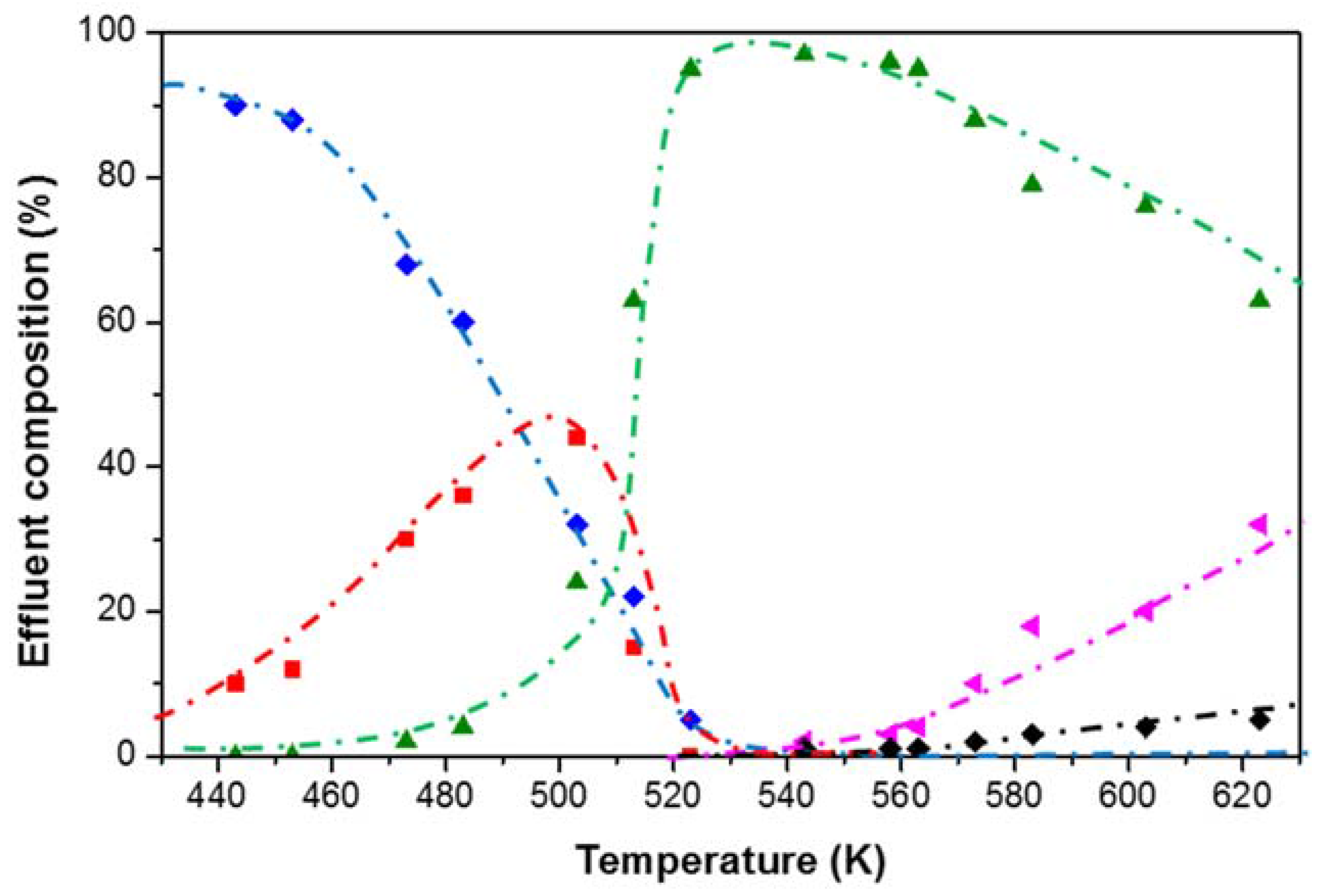
4. Case Study: Ethanol Conversion to Hydrocarbons

The application of the proposed information-driven catalyst design methodology and the use of the corresponding set-ups is illustrated by the efforts related to (bio)ethanol conversion to hydrocarbons [40]. Ethanol conversion to hydrocarbons on H-ZSM-5 opens up perspectives for a sustainable light olefins production such as ethene and propene, which are the key building blocks for polyethene and polypropene. In view of industrial application and large scale operation, a lot of research has been performed to enhance the catalyst performance by tuning their properties. This includes, among others, the investigation of different topologies [41], metal modification [42,43], framework modification [44,45] and phosphorus introduction [46]. Furthermore, the reaction mechanism of ethanol conversion to hydrocarbons is still a matter of debate [47,48,49]. In addition to the complexity brought about by a multitude of post synthesis modifications methods, the assessment of reported catalyst performance in ethanol conversion is often challenging because of the large variety of reaction conditions employed and catalyst properties investigated.
During experimentation, the mass balance was always determined via an internal standard as this reflects the accuracy and correctness of the performed experiments. As indicated in Section 3, the internal standard is added downstream for the HTK-S and upstream of the reactor HTK-MI set-up. Both methods are equivalent as long as the internal standard is inert. In both cases, methane was used as internal standard. It was verified that no methane conversion or formation in ethanol conversion occurred at the most severe operating conditions used. Using the internal standard, the mass and elemental balances for all experiments were verified to be closed within 5%.
The most important prerequisite for correct interpretation and utilization of information driven catalyst design is the acquisition of reliable intrinsic kinetic data [36]. External mass transfer limitations, if any, are quantified by the Carberry number (Ca) [50] while internal ones are verified by the Weisz-Prater criterion [51]. The absence of internal and external heat transfer limitations is validated by the Mears criterion [52]. A tubular reactor is said to be operated in plug flow regime when the axial dispersion can be neglected [53] and uniformity in the radial direction is achieved [54]. It also requires a minimal pressure drop over the catalyst bed. It was validated that all criteria were met in both set-ups, as can be seen in Table 2. This validation was done for the most severe operation conditions, being the highest temperature used in this study.
Table 2. Calculated versus limit values in the criteria for intrinsic kinetics evaluation at the most severe operating conditions used for ethanol conversion to hydrocarbons (T = 623 K, PEtOH =20 kPa, W/F°EtOH = 17 kg·s·mol−1).
PhenomenonCriterionHTK-SHTK-MI
Mass transferexternal Ca2.9 × 10−4 < 0.055.3 × 10−3 < 0.05
internal Φ9.7 × 10⁻² < 0.083.0 × 10−3 < 0.08
Heat transferexternal ΔText1.3 × 10−2 < 2.0 K1.4 × 10−1 < 6.0 K
internal ΔTint1.4 × 10−3 < 2.0 K5.1 × 10−3 < 6.0 K
Flow pattern ideality
Plug flow
radial dispersiondt/dp24 > 816 > 8
axial dispersionLB/dp1074 > 50519 > 50
pressure dropΔP/P7.5 × 10−2 < 0.21.1 × 10−3 < 0.2

4.1. Catalyst Screening (HTK-S Set-Up)

First, several catalyst samples are considered for the initial catalyst screening with the HTK-S set-up. In total, 15 catalyst samples were selected, i.e., three pristine H-ZSM-5 (Si/Al = 15, 25 and 40) and 12 iron (Fe), gallium (Ga) or nickel (Ni) containing ZSM-5 samples derived from the pristine H-ZSM-5 with aSi/Al = 15. The metal content varied between 0.5% and 7%. The catalysts were compared at identical reaction conditions, i.e., at a temperature (T) of 623 K, a fixed space time (W/F°EtOH) of 17 kg·s·mol−1 and fixed ethanol partial pressure (pEtOH) of 10 kPaAs can be seen from Figure 6, the lowest metal containing ZSM-5 exhibited a higher activity compared to the parent H-ZSM-5 (Si/Al = 15) [40]. As the metal content increases, the activity decreases in a similar manner as it occurs with an increasing Si/Al ratio. This behavior was found to correspond with the acid site concentration: small metal amounts resulted in an increase of the acid site concentration while metal oxides were formed at higher metal contents which cause pore blocking and decrease the accessibility of the acid sites. The acid site strength was found only to be affected at high metal loading. Furthermore, it was found that increasing the metal content did not significantly alter the product selectivity. These observations resulted in the selection of unmodified H-ZSM-5 as benchmark catalysts because of their commercial availability. The sample with a Si/Al = 15 was selected, as it exhibited the highest activity and also best guaranteed reproducible synthesis.
Figure 6. Catalyst screening on the HTK-S of different ZSM-5 catalysts including Fe, Ni and Ga modified ZSM-5 with different metal content (indicated as bars) and unmodified H-ZSM-5 with different Si/Al (indicated as lines in xz plane: full: Si/Al = 15; dashed: Si/Al = 25 and dot dash: Si/Al = 40) and its effect on the conversion(T = 623 K; pEtOH = 10 kPa, W/F°EtOH = 17 kg·s·mol−1, treact = 2 h).
Catalysts 05 01948 g006

4.2. Mechanistic Investigation (HTK-MI Set-Up)

The next step is to gain more fundamental insight in the reaction mechanism governing the ethanol to hydrocarbons conversion. This was initiated via a performance screening over a broad temperature range at fixed space time and ethanol inlet partial pressure as shown in Figure 7.
Figure 7. Effect of temperature on effluent composition on H-ZSM-5 (Si/Al = 15) (pEtOH = 20 kPa; W/F°EtOH = 8 kg·s·mol−1, treact = 2 h) (blue: ethanol; red: diethyl ether; green: ethene; magenta: C3 and C4 olefins; black: C5+ hydrocarbons), as measured on the HTK-MI [40].
Catalysts 05 01948 g007
At low temperatures, i.e., below 500 K, diethyl ether is the primary product resulting from the bimolecular reaction as shown in Equation (2). Upon a temperature increase, the ethene yield increases. This ethene is produced either via the decomposition of diethyl ether Equation (3) or the monomolecular dehydration of ethanol Equation (4):
2  C 2 H 5 OH C 2 H 5 OC 2 H 5 + H 2 O
C 2 H 5 OC 2 H 5 C 2 H 4 + C 2 H 5 OH
C 2 H 5 OH C 2 H 4 + H 2 O
A detailed reaction mechanism for ethanol dehydration was already theoretically elucidated using quantum chemical techniques [55]. Complete ethanol conversion is reached at temperatures exceeding 540 K, simultaneously leading to the formation of C3+ hydrocarbons. At even higher temperatures, a wide variety of olefins up to C8 are formed. More elaborate intrinsic kinetic testing is currently ongoing.
Given the different possibilities for catalyst optimization, i.e., maximizing the production of diethyl ether as diesel additive [56], ethene as precursor for polyethene, propene as monomer for polypropene or C5+ hydrocarbons as alternative feedstock for gasoline, it is believed that no single optimal catalyst exists for ethanol to hydrocarbon conversion. Rather, making use of a fundamental, microkinetic model, the ideal catalyst descriptors and operating conditions can be determined for each of the potentially desired product slate.
As the intrinsic kinetics character of the measurements has been verified, the obtained results can be used as input for the construction of such a microkinetic model. Considering the complexity of the effluent comprising over more than 100 compounds, the Single-Event Microkinetic (SEMK) methodology would be ideally suited for this endeavor in order to limit the number of adjustable parameters. It proved already to be successful for acid catalyzed processes such as hydrocracking [57] and oligomerization [58] but also for metal catalysis [59]. An example of proper catalyst assessment and how intrinsic kinetics measurements can be used in a micro kinetic model has recently also been implemented for oxidative coupling of methane [27].

5. Conclusions and Perspectives

A novel catalyst design methodology based on fundamental, microkinetic modeling has been described. The experimental efforts require two correspondingly developed high-throughput kinetic set-ups for screening (HTK-S) and mechanistic investigations (HTK-MI). The former focuses on acquiring as much information as possible on a wide variety of catalysts while the latter is used for in-depth studies on the reaction mechanisms and effects of catalyst properties on the kinetics. This information is integrated in a (micro)kinetic model that is able to describe the reaction in a fundamental manner. The construction of such kinetic models, including kinetic and catalyst descriptors, allows the in-silico design of new, non-explored and better performing catalysts. The actual synthesis of these enhanced catalysts and subsequent screening verifies the validity of the model and, hence, of the methodology.
Specifically for large scale chemical reactions, statistics- and performance-driven catalyst design are believed to have reached their limits for further catalyst improvement. The lack of fundamental insights in the relevant phenomena hinders the development of novel and improved catalyst formulations according to these methodologies. Information-driven catalyst design is particularly interesting for reactions for which small catalyst improvements will lead to a high profit increase.
Given the transition from conventional fossil to alternative fossil and renewable feedstocks, alcohol conversion, hydrodeoxygenation and hydrogenolysis, are promising candidate reactions for catalyst optimization according to the proposed methodology. All reactions have in common that they are governed by a complex reaction network, certainly when heteroatoms are present. This complexity requires a fundamental understanding to effectively optimize catalyst performance.

Acknowledgments

This work was supported by the “Long Term Structural Methusalem Funding by the Flemish Government”, the Interuniversity Attraction Poles Program-Belgian State-Belgian Science Policy and the Fund for Scientific Research Flanders (FWO). The research leading to these results has also received funding from the European Research Council under the European Union’s Seventh Framework Program (FP7/2007-2013)/ERC grant agreement No. 615456.

Author Contributions

K.B., K.T., J.W.T. and G.B.M. conceived the methodology. K.B conducted the experiments. K.B and V.G analyzed the experimental data. K.B. wrote the paper. K.T., J.W.T., V.G and G.B.M. revised the paper. All authors read and provided feedback during preparation of the manuscript.

Conflicts of Interest

The authors declare no conflict of interest.

Nomenclature

Roman
biparameter -
CaCarberry number -
Fimolar flow rate of component imol·s−1
Llengthm
ddiameter m
ppressurePa
pipartial pressure of component iPa
Ttemperature K
ttime h
Wcatalyst masskg
xfactor-
Youtput variable-
Greek
ФWeisz modulus-
Subscripts
Bbed-
Capcapillary-
Ggas-
EtOHethanol-
Idinternal diameter-
Lliquid-
maxmaximum-
minminimum-
Ppellet-
Reactreaction-
Ttotal-
Superscripts
°inlet

References

  1. Norskov, J.K.; Bligaard, T.; Rossmeisl, J.; Christensen, C.H. Towards the computational design of solid catalysts. Nat. Chem. 2009, 1, 37–46. [Google Scholar] [CrossRef] [PubMed]
  2. Senkan, S.M. High-throughput screening of solid-state catalyst libraries. Nature 1998, 394, 350–353. [Google Scholar] [CrossRef]
  3. Senkan, S. Combinatorial heterogeneous catalysis—A new path in an old field. Angew. Chem. Int. Ed. 2001, 40, 312–329. [Google Scholar] [CrossRef]
  4. Hoogenboom, R.; Meier, M.A.R.; Schubert, U.S. Combinatorial methods, automated synthesis and high-throughput screening in polymer research: Past and present. Macromol. Rapid. Commun. 2003, 24, 16–32. [Google Scholar] [CrossRef]
  5. Smil, V. Enriching the Earth: Fritz Haber, Carl Bosch, and the Transformation of World Food Production; MIT Press: Cambridge, MA, USA, 2001; p. 338. [Google Scholar]
  6. Maier, W.F.; Stowe, K.; Sieg, S. Combinatorial and high-throughput materials science. Angew. Chem. Int. Ed. 2007, 46, 6016–6067. [Google Scholar] [CrossRef] [PubMed]
  7. Cong, P.J.; Doolen, R.D.; Fan, Q.; Giaquinta, D.M.; Guan, S.H.; McFarland, E.W.; Poojary, D.M.; Self, K.; Turner, H.W.; Weinberg, W.H. High-throughput synthesis and screening of combinatorial heterogeneous catalyst libraries. Angew. Chem. Int. Ed. 1999, 38, 484–488. [Google Scholar] [CrossRef]
  8. Newsam, J.M.; Bein, T.; Klein, J.; Maier, W.F.; Stichert, W. High throughput experimentation for the synthesis of new crystalline microporous solids. Microporous Mesoporous Mater. 2001, 48, 355–365. [Google Scholar] [CrossRef]
  9. Boussie, T.R.; Diamond, G.M.; Goh, C.; Hall, K.A.; LaPointe, A.M.; Leclerc, M.; Lund, C.; Murphy, V.; Shoemaker, J.A.; Tracht, U.; et al. A fully integrated high-throughput screening methodology for the discovery of new polyolefin catalysts: Discovery of a new class of high temperature single-site group (IV) copolymerization catalysts. J. Am. Chem. Soc. 2003, 125, 4306–4317. [Google Scholar] [CrossRef] [PubMed]
  10. Farrusseng, D. High-throughput heterogeneous catalysis. Surf. Sci. Rep. 2008, 63, 487–513. [Google Scholar] [CrossRef]
  11. Montgomery, D.C. Design and Analysis of Experiments, 2nd ed.; Wiley: New York, NY, USA, 1984; p. 538. [Google Scholar]
  12. Wolf, D.; Buyevskaya, O.V.; Baerns, M. An evolutionary approach in the combinatorial selection and optimization of catalytic materials. Appl. Catal. A 2000, 200, 63–77. [Google Scholar] [CrossRef]
  13. Caruthers, J.M.; Lauterbach, J.A.; Thomson, K.T.; Venkatasubramanian, V.; Snively, C.M.; Bhan, A.; Katare, S.; Oskarsdottir, G. Catalyst design: Knowledge extraction from high-throughput experimentation. J. Catal. 2003, 216, 98–109. [Google Scholar] [CrossRef]
  14. Baumes, L.A.; Serna, P.; Corma, A. Merging traditional and high-throughput approaches results in efficient design, synthesis and screening of catalysts for an industrial process. Appl. Catal. A 2010, 381, 197–208. [Google Scholar] [CrossRef]
  15. Huybrechts, W.; Mijoin, J.; Jacobs, P.A.; Martens, J.A. Development of a fixed-bed continuous-flow high-throughput reactor for long-chain N-alkane hydroconversion. Appl. Catal. A 2003, 243, 1–13. [Google Scholar] [CrossRef]
  16. Perez-Ramirez, J.; Berger, R.J.; Mul, G.; Kapteijn, F.; Moulijn, J.A. The six-flow reactor technology—A review on fast catalyst screening and kinetic studies. Catal. Today 2000, 60, 93–109. [Google Scholar] [CrossRef]
  17. Nagy, A.J. Implementation of High Throughput Experimentation Techniques for Kinetic Reaction Testing. Comb. Chem. High Throughput Screen. 2012, 15, 189–198. [Google Scholar] [CrossRef] [PubMed]
  18. Navidi, N.; Thybaut, J.W.; Marin, G.B. Experimental investigation of ethylene hydroformylation to propanal on Rh and Co based catalysts. Appl. Catal. A 2014, 469, 357–366. [Google Scholar] [CrossRef]
  19. Chheda, J.N.; Huber, G.W.; Dumesic, J.A. Liquid-phase catalytic processing of biomass-derived oxygenated hydrocarbons to fuels and chemicals. Angew. Chem. Int. Ed. 2007, 46, 7164–7183. [Google Scholar] [CrossRef] [PubMed]
  20. Hagemeyer, A.; Strasser, P.; Volpe, A. High-Throughput Screening in Chemical Catalysis: Technologies, Strategies and Applications; John Wiley & Sons: Weinheim; Germany, 2004. [Google Scholar]
  21. Shimizu, K.D.; Snapper, M.L.; Hoveyda, A.H. High-throughput strategies for the discovery of catalysts. Chem. Eur. J. 1998, 4, 1885–1889. [Google Scholar] [CrossRef]
  22. Cawse, J.N. Experimental Strategies for Combinatorial and High-Throughput Materials Development. Acc. Chem. Res. 2001, 34, 213–221. [Google Scholar] [CrossRef] [PubMed]
  23. Massart, D.L. Handbook of Chemometrics and Qualimetrics; Elsevier: Amsterdam, The Nertherland; New York, NY, USA, 1997. [Google Scholar]
  24. Hendershot, R.J.; Snively, C.M.; Lauterbach, J. High-Throughput Heterogeneous Catalytic Science. Chem. Eur. J. 2005, 11, 806–814. [Google Scholar] [CrossRef] [PubMed]
  25. Thybaut, J.W.; Marin, G.B. Single-Event MicroKinetics: Catalyst design for complex reaction networks. J. Catal. 2013, 308, 352–362. [Google Scholar] [CrossRef]
  26. Thybaut, J.W.; Choudhury, I.R.; Denayer, J.F.; Baron, G.V.; Jacobs, P.A.; Martens, J.A.; Marin, G.B. Design of Optimum Zeolite Pore System for Central Hydrocracking of Long-Chain N-Alkanes based on a Single-Event Microkinetic Model. Top. Catal. 2009, 52, 1251–1260. [Google Scholar] [CrossRef]
  27. Alexiadis, V.I.; Thybaut, J.W.; Kechagiopoulos, P.N.; Chaar, M.; Van Veen, A.C.; Muhler, M.; Marin, G.B. Oxidative coupling of methane: Catalytic behaviour assessment via comprehensive microkinetic modelling. Appl. Catal. B 2014, 150, 496–505. [Google Scholar] [CrossRef]
  28. Vandegehuchte, B.D.; Thybaut, J.W.; Marin, G.B. Unraveling Diffusion and Other Shape Selectivity Effects in ZSM5 Using N-Hexane Hydroconversion Single-Event Microkinetics. Ind. Eng. Chem. Res. 2014, 53, 15333–15347. [Google Scholar] [CrossRef]
  29. Vandegehuchte, B.D.; Choudhury, I.R.; Thybaut, J.W.; Martens, J.A.; Marin, G.B. Integrated Stefan-Maxwell, Mean Field, and Single-Event Microkinetic Methodology for Simultaneous Diffusion and Reaction inside Microporous Materials. J. Phys. Chem. C 2014, 118, 22053–22068. [Google Scholar] [CrossRef]
  30. Dewachtere, N.V.; Santaella, F.; Froment, G.F. Application of a single-event kinetic model in the simulation of an industrial riser reactor for the catalytic cracking of vacuum gas oil. Chem. Eng. Sci. 1999, 54, 3653–3660. [Google Scholar] [CrossRef]
  31. Lozano-Blanco, G.; Thybaut, J.W.; Surla, K.; Galtier, P.; Marin, G.B. Simulation of a Slurry-Bubble Column Reactor for Fischer-Tropsch Synthesis Using Single-Event Microkinetics. AIChE J. 2009, 55, 2159–2170. [Google Scholar] [CrossRef]
  32. Froment, G.F. Modeling of catalyst deactivation. Appl. Catal. A 2001, 212, 117–128. [Google Scholar] [CrossRef]
  33. Vandegehuchte, B.D.; Thybaut, J.W.; Martens, J.A.; Marin, G.B. Maximizing N-alkane hydroisomerization: The interplay of phase, feed complexity and zeolite catalyst mixing. Catal. Sci. Technol. 2015, 5, 2053–2058. [Google Scholar] [CrossRef]
  34. Van Herk, D.; Kreutzer, M.T.; Makkee, M.; Moulijn, J.A. Scaling down trickle bed reactors. Catal. Today 2005, 106, 227–232. [Google Scholar] [CrossRef]
  35. Nagy, A. Integrated Lab Solutions. Available online: http://www.integratedlabsolutions.com/ (accessed on 23 September 2015).
  36. Berger, R.J.; Stitt, E.H.; Marin, G.B.; Kapteijn, F.; Moulijn, J.A. Eurokin—Chemical reaction kinetics in practice. Cattech 2001, 5, 30–60. [Google Scholar] [CrossRef]
  37. Al-Dahhan, M.H.; Wu, Y.; Dudukovic, M.P. Reproducible Technique for Packing Laboratory-Scale Trickle-Bed Reactors with a Mixture of Catalyst and Fines. Ind. Eng. Chem. Res. 1995, 34, 741–747. [Google Scholar] [CrossRef]
  38. Van Herk, D.; Castaño, P.; Quaglia, M.; Kreutzer, M.T.; Makkee, M.; Moulijn, J.A. Avoiding segregation during the loading of a catalyst—Inert powder mixture in a packed micro-bed. Appl. Catal. A 2009, 365, 110–121. [Google Scholar] [CrossRef]
  39. Zeton. Available online: http://www.zeton.com/site/home.html (accessed on 23 September 2015).
  40. Van der Borght, K.; Galvita, V.V.; Marin, G.B. Ethanol to higher hydrocarbons over Ni, Ga, Fe-modified ZSM-5: Effect of metal content. Appl. Catal. A 2015, 492, 117–126. [Google Scholar] [CrossRef]
  41. Madeira, F.F.; Gnep, N.S.; Magnoux, P.; Maury, S.; Cadran, N. Ethanol transformation over HFAU, HBEA and HMFI zeolites presenting similar Brønsted acidity. Appl. Catal. A 2009, 367, 39–46. [Google Scholar] [CrossRef]
  42. Machado, N.R.C.F.; Calsavara, V.; Astrath, N.G.C.; Medina, A.; Baesso, M.L. Hydrocarbons from ethanol using [Fe,Al]ZSM-5 zeolites obtained by direct synthesis. Appl. Catal. A 2006, 311, 193–198. [Google Scholar] [CrossRef]
  43. Gayubo, A.G.; Alonso, A.; Valle, B.; Aguayo, A.T.; Olazar, M.; Bilbao, J. Kinetic modelling for the transformation of bioethanol into olefins on a hydrothermally stable Ni-HZSM-5 catalyst considering the deactivation by coke. Chem. Eng. J. 2011, 167, 262–277. [Google Scholar] [CrossRef]
  44. Gayubo, A.G.; Alonso, A.; Valle, B.; Aguayo, A.T.; Bilbao, J. Selective production of olefins from bioethanol on HZSM-5 zeolite catalysts treated with NaOH. Appl. Catal. B 2010, 97, 299–306. [Google Scholar] [CrossRef]
  45. Xin, H.; Li, X.; Fang, Y.; Yi, X.; Hu, W.; Chu, Y.; Zhang, F.; Zheng, A.; Zhang, H.; Li, X. Catalytic dehydration of ethanol over post-treated ZSM-5 zeolites. J. Catal. 2014, 312, 204–215. [Google Scholar] [CrossRef]
  46. Song, Z.; Takahashi, A.; Nakamura, I.; Fujitani, T. Phosphorus-modified ZSM-5 for conversion of ethanol to propylene. Appl. Catal. A 2010, 384, 201–205. [Google Scholar] [CrossRef]
  47. Gayubo, A.G.; Tarrío, A.M.; Aguayo, A.T.; Olazar, M.; Bilbao, J. Kinetic Modelling of the Transformation of Aqueous Ethanol into Hydrocarbons on a HZSM-5 Zeolite. Ind. Eng. Chem. Res. 2001, 40, 3467–3474. [Google Scholar] [CrossRef]
  48. Johansson, R.; Hruby, S.L.; Rass-Hansen, J.; Christensen, C.H. The Hydrocarbon Pool in Ethanol-to-Gasoline over HZSM-5 Catalysts. Catal. Lett. 2009, 127, 1–6. [Google Scholar] [CrossRef]
  49. Madeira, F.F.; Gnep, N.S.; Magnoux, P.; Vezin, H.; Maury, S.; Cadran, N. Mechanistic insights on the ethanol transformation into hydrocarbons over HZSM-5 zeolite. Chem. Eng. J. 2010, 161, 403–408. [Google Scholar] [CrossRef]
  50. Mears, D.E. Tests for Transport Limitations in Experimental Catalytic Reactors. Ind. Eng. Chem. Process. Dis. Dev. 1971, 10, 541–547. [Google Scholar] [CrossRef]
  51. Weisz, P.B.; Prater, C.D. Interpretation of Measurements in Experimental Catalysis. In Advances in Catalysis; Frankenburg, V.I.K., Rideal, E.K., Eds.; Academic Press: New York, NY, USA, 1954; Volume 6, pp. 143–196. [Google Scholar]
  52. Mears, D.E. Diagnostic Criteria for Heat Transport Limitations in Fixed Bed Reactors. J. Catal. 1971, 20, 127–131. [Google Scholar] [CrossRef]
  53. Mears, D.E. The role of axial dispersion in trickle-flow laboratory reactors. Chem. Eng. Sci. 1971, 26, 1361–1366. [Google Scholar] [CrossRef]
  54. Chu, C.F.; Ng, K.M. Flow in packed tubes with a small tube to particle diameter ratio. AIChE J. 1989, 35, 148–158. [Google Scholar] [CrossRef]
  55. Reyniers, M.F.; Marin, G.B. Experimental and Theoretical Methods in Kinetic Studies of Heterogeneously Catalyzed Reactions. Annu. Rev. Chem. Biomol. Eng. 2014, 5, 563–594. [Google Scholar] [CrossRef] [PubMed]
  56. Rakopoulos, D.C.; Rakopoulos, C.D.; Giakoumis, E.G.; Dimaratos, A.M. Characteristics of performance and emissions in high-speed direct injection diesel engine fueled with diethyl ether/diesel fuel blends. Energy 2012, 43, 214–224. [Google Scholar] [CrossRef]
  57. Thybaut, J.W.; Marin, G.B.; Baron, G.V.; Jacobs, P.A.; Martens, J.A. Alkene protonation enthalpy determination from fundamental kinetic modeling of alkane hydroconversion on Pt/H-(US)Y-zeolite. J. Catal. 2001, 202, 324–339. [Google Scholar] [CrossRef]
  58. Toch, K.; Thybaut, J.W.; Marin, G.B. Ethene oligomerization on Ni-SiO2-Al2O3: Experimental investigation and Single-Event MicroKinetic modeling. Appl. Catal. A 2015, 489, 292–304. [Google Scholar] [CrossRef]
  59. Lozano-Blanco, G.; Thybaut, J.W.; Surla, K.; Galtier, P.; Marin, G.B. Single-event microkinetic model for Fischer-Tropsch synthesis on iron-based catalysts. Ind. Eng. Chem. Res. 2008, 47, 5879–5891. [Google Scholar] [CrossRef]

