Article

Nanostructured Carbon Materials as Supports in the Preparation of Direct Methanol Fuel Cell Electrocatalysts

1
Instituto de Carboquímica (CSIC), Miguel Luesma Castán 4, 50018 Zaragoza, Spain
2
Departamento de Química Física, Universidad de la Laguna, San Cristobal la Laguna 38071, Tenerife, Spain
3
Aragon Institute for Engineering Research-I3A, Universidad de Zaragoza, Mariano Esquillor s/n 50018 Zaragoza, Spain
*
Author to whom correspondence should be addressed.
Catalysts 2013, 3(3), 671-682; https://doi.org/10.3390/catal3030671
Submission received: 19 July 2013 / Revised: 7 August 2013 / Accepted: 12 August 2013 / Published: 21 August 2013
(This article belongs to the Special Issue Carbon Catalysts)

Abstract

:
Different advanced nanostructured carbon materials, such as carbon nanocoils, carbon nanofibers, graphitized ordered mesoporous carbons and carbon xerogels, presenting interesting features such as high electrical conductivity and extensively developed porous structure were synthesized and used as supports in the preparation of electrocatalysts for direct methanol fuel cells (DMFCs). The main advantage of these supports is that their physical properties and surface chemistry can be tailored to adapt the carbonaceous material to the catalytic requirements. Moreover, all of them present a highly mesoporous structure, diminishing diffusion problems, and both graphitic character and surface area can be conveniently modified. In the present work, the influence of the particular features of each material on the catalytic activity and stability was analyzed. Results have been compared with those obtained for commercial catalysts supported on Vulcan XC-72R, Pt/C and PtRu/C (ETEK). Both a highly ordered graphitic and mesopore-enriched structure of these advanced nanostructured materials resulted in an improved electrochemical performance in comparison to the commercial catalysts assayed, both towards CO and alcohol oxidation.

1. Introduction

Among the different types of fuel cells, polymer electrolyte fuel cells (PEMFCs and DAFCs, respectively using hydrogen and alcohols such as methanol or ethanol) are the most promising for both portable and stationary applications due to their advantageous features such as high power density at lower temperatures (55–95 °C), low weight, compactness, and suitability for discontinuous operation [1,2]. At present, the most effective fuel cell catalysts are based on highly dispersed platinum-based nanoparticles. The high cost of noble metals used as electrode catalysts is one of the significant obstacles for the commercialization of PEMFCs. Therefore, the metal nanoparticles are normally deposited on advanced supports, such as doped titanium oxide [3], tungsten trioxide-doped ordered mesoporous carbons [4], or, in general, advanced carbon materials in order to maximize their surface area and decrease the total amount of metal employed. Thus, the fraction of metal particles exposed to the reactants increases, improving the catalysts utilization [5]. Among other factors, the performance of metal nanoparticles supported on carbon materials depends strongly on the properties of the support.
On the other hand, in spite of the fact that platinum is the best catalyst for alcohol oxidation, its surface is quickly poisoned by irreversible adsorbed CO, which results from the dissociative adsorption of alcohols. Recent studies have shown that using bimetallic catalysts (generally Ruthenium, which forms the Pt-Ru alloy) supported onto different carbon materials the catalytic activity and the selectivity for complete oxidation of the alcohols can be improved [6,7,8,9,10]. Among other factors, the performance of Pt or Pt-Ru nanoparticles supported on carbon materials depends strongly on the properties of the support and on the structure, crystallite size and dispersion of metal nanoparticles.
Different carbon materials with interesting textural and structural properties, such as high surface area, high mesopore volume and high electrical conductivity, are considered in the present work as electrocatalyst support for the preparation of direct methanol fuel cells (DMFCs) anodes. The aim is to study the influence of textural and structural properties of such supports on the catalytic activity, in order to improve their efficiency and stability in the fuel cell. A carbon nanocoil, a carbon nanofiber and a carbon xerogel have been used for synthesizing platinum and platinum-ruthenium catalysts.

2. Results and Discussion

2.1. Carbon Materials Characterization

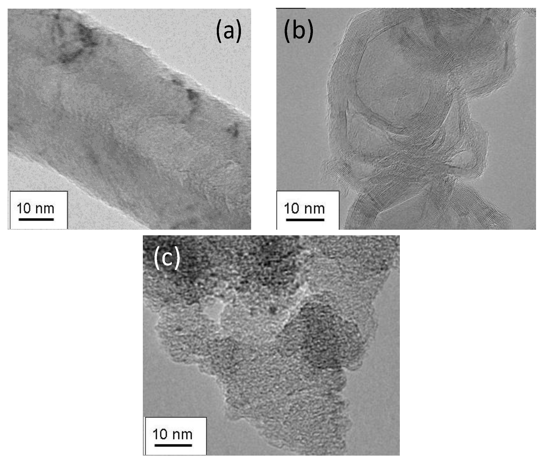
The morphology of the prepared carbonaceous materials was studied by TEM. Some representative images are shown in Figure 1. The basic structure of carbon nanofibers (CNF) consists of highly entangled filaments of ca. 60 nm diameter. An image of an individual nanofiber can be observed in Figure 1a. A single nanocoil exhibited well-aligned graphitic layers as can be also observed in Figure 1b. The nanocoils have a diameter of around 30–40 nm and consist of a long curved ribbon of carbon. On the other hand, carbon xerogel is constituted by amorphous carbon which forms coralline-like structures, as can be envisaged from Figure 1c.
The textural properties of the carbon materials were studied by N2-physisorption (Table 1). The presented supports have a specific area between 101 and 441 m2 g−1 and pore volumes between 0.16 and 1.62 cm3 g−1.
Table 1. Textural parameters of the different carbon supports.
SBET (m2 g−1)Vtotal (cm3 g−1)SMeso (m2 g−1)VMeso (cm3 g−1)
CNF1010.38910.38
CNC1240.161240.16
CXG4411.622511.53
Figure 1. TEM images for (a) carbon nanofiber; (b) carbon nanocoil; (c) carbon xerogel.
Catalysts 03 00671 g001
In the case of CNF and CNC, the porosity corresponds to interparticular spaces, which leads to a highly mesoporous structure, whereas in the case of CXG, porosity is a consequence of both the interparticular spaces and the intraparticle voids. CNC showed a bimodal pore size distribution in the range of mesoporosity with average pore diameters of around 3 and 15 nm, whereas CNF showed a wide pore size distribution in the range of mesopores, as a result of their filamentous structure. CXG showed a pore size distribution centered at 23 nm, as a result of the synthesis conditions employed.
Textural characterization was repeated after the introduction of both Pt and PtRu. Metals are mostly deposited on the mesoporous fraction of the support’s porosity. Pore blockage occurs to a certain extent, however, especially in the case of the CXG-based catalysts, the average pore size is well maintained after the synthesis of the catalysts. Note that, in comparison to the commercial catalysts, prepared using a carbon black as support, average pore size in the catalyst Pt/CXG and PtRu/CXG are around 23 nm, which doubles the average size measured for the commercial system.
The surface chemistry of the different supports was studied by means of temperature programmed desorption (TPD). The total CO2 and CO evolved from the samples, together with the estimated total oxygen content, are summarized in Table 2. The results evidence a more functionalized surface for the CXG, in comparison to CNC and CNF. This is especially remarkable in terms of more stable surface funcitonalities, evolving as CO in TPD, which is double in the case of the CXG than for CNC.
Table 2. CO and CO2 desorbed from the different carbon supports in temperature programmed desorption (TPD) experiments.
CO2 (mmol g−1)CO (mmol g−1)O content (wt.%)
CNF0.321.072.7
CNC0.852.346.5
CXG0.994.4510.3
The as-prepared carbon materials were used to prepare platinum supported electrocatalysts by the sodium borohydride method. The metal loading of the catalysts was determined by using SEM-EDX and the results are compiled in Table 3. In all cases, the values obtained were close to the nominal value of 20%. The average Pt crystallite size derived from the XRD (220) peak broadening (not shown) is summarized in Table 4 for all the catalysts. It is remarkable that the crystal size progressively decreases as the support surface area increases from CNF (6.8 nm and 101 m2 g−1) to CXG (4.1 nm and 441 m2 g−1).
Table 3. Pt content from EDX and average crystallite size from XRD analysis of the catalysts.
Pt content (wt.%)Crystallite size (nm)
Pt/CNF19.26.8
Pt/CNC20.04.7
Pt/CXG21.04.1
The as-prepared carbon materials were also used to prepare platinum-ruthenium supported electrocatalysts. The metal loading of the catalysts was determined using SEM-EDX and the results are compiled in Table 4. In all cases, the values obtained were close to the nominal value of 20.0%.
Crystallite size decreases in all cases upon the introduction of Ru. This is due to the partial introduction of Ru into the fcc structure of Pt, causing a shrinkage of the crystalline lattice. Catalysts supported on CNF and on CXG show similar PtRu crystallite sizes, i.e., 2.3 and 2.5 nm respectively, whereas for the CNC supported catalysts, crystallite size is bigger, 3.9 nm. However, this differences can be due to the different Pt:Ru atomic ratios in each system. Additionally, platinum-ruthenium catalysts were prepared by different methods, being the microemulsion route the method used for the synthesis of PtRu/CNF and the impregnation-reduction route the method used for both PtRu/CNC and PtRu/CXG. Synthesis method may have some influence as well in the crystallite size in each case [11].
Table 4. PtRu content from EDX and average crystallite size from XRD analysis of the catalysts.
PtRu content (wt.%)Atomic ratio Pt:RuCrystallite size (nm)
PtRu/CNF21.047:532.3
PtRu/CNC17.366:343.9
PtRu/CXG24.050:502.5

2.2. Electrochemical Characterization and Activity

Figure 2 shows the cyclic voltammograms for the different electrocatalysts obtained during the stripping of a CO monolayer formed at 0.20 V vs. RHE, as well as the second cycle after CO oxidation, which corresponds to the voltammogram in the base electrolyte (H2SO4 0.5 M) for the clean Pt surface. A carbon supported platinum electrocatalyst (E-TEK) has been included for comparison.
In general terms, two current contributions are found for the catalysts supported on the nanostructured carbon materials at potentials in the interval 0.60–0.85 V vs. RHE, in contrast to the commercial electrocatalyst, which presents a single oxidation peak centered at 0.86 V vs. RHE. The use of advanced carbon supports represents a clear advantage in terms of CO tolerance as Pt supported on these materials is less susceptible to CO poisoning than the commercial catalyst.
There are also remarkable differences between the different supports in terms of CO oxidation. Between the two current contributions observed for all of them, the catalysts supported on CNC presents the highest contribution to more negative potential (ca. 0.71 V vs. RHE), followed by CNF and CXG. This could be ascribed to a metal-support effect improved with highly graphitic carbon materials.
Figure 2. Cyclic voltammograms recorded at 25 °C and 20 mV s−1 during the CO stripping for the Pt electrocatalysts supported on the different carbon supports.
Catalysts 03 00671 g002
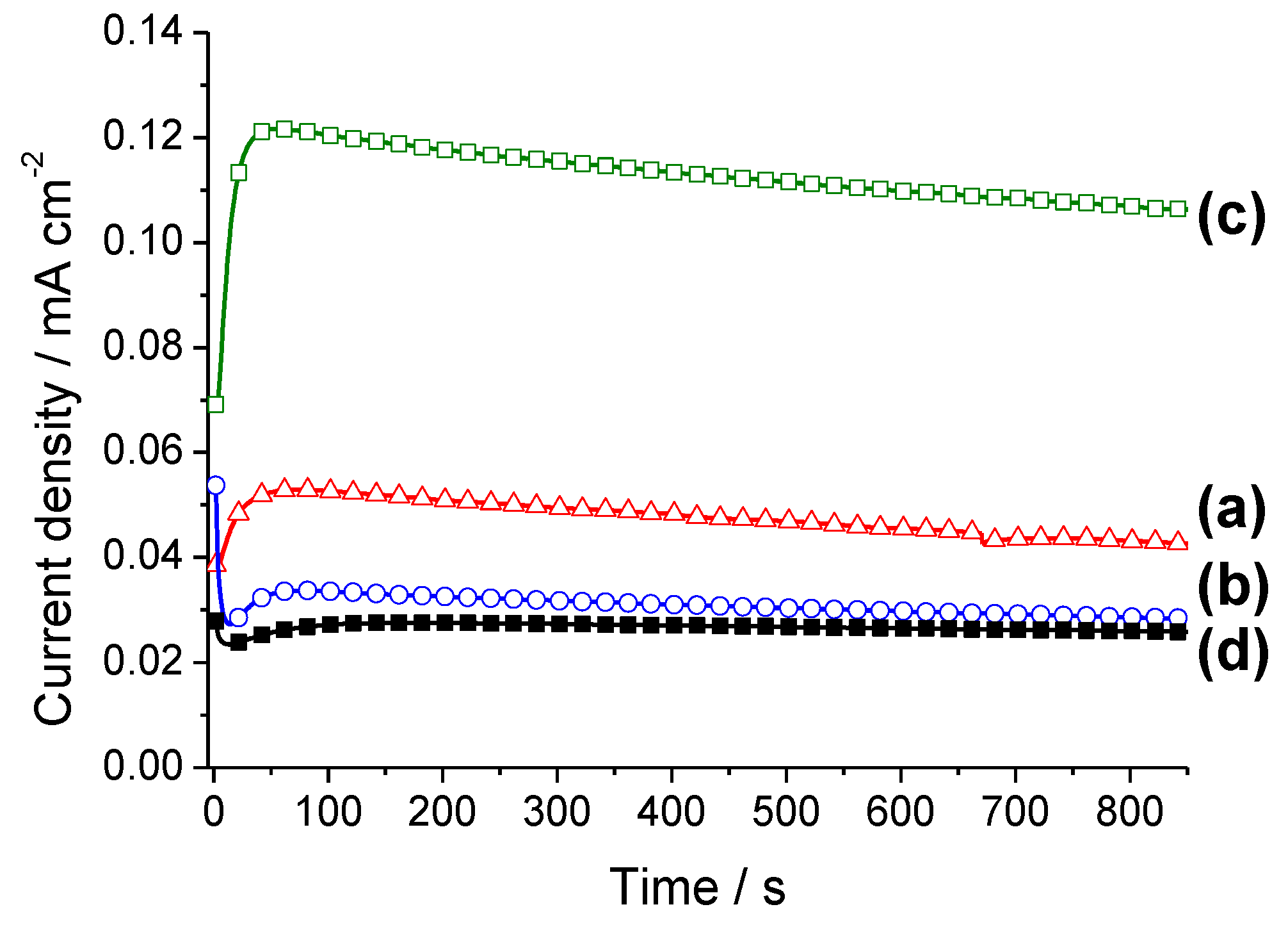
Figure 3. Current density-time curves recorded in 2 M methanol + 0.5 M H2SO4 solution at E = 0.60 V vs. RHE for (a) Pt/CNF; (b) Pt/CNC; (c) Pt/CXG and (d) Pt/C (E-TEK).
Catalysts 03 00671 g003
Methanol oxidation electrochemical experiments were conducted to study the performance of the electrocatalysts in the anodic reaction of DMFCs. It has to be considered that the best catalyst for the oxidation of CO is not necessarily the best for the oxidation of methanol. The latter reaction implies the deprotonation of the alcohol to produce adsorbed CO, which further oxidizes. Current-time curves were recorded at 0.60 V vs. RHE and 25 °C during 850 s in a 2 M CH3OH solution prepared in the base electrolyte, as shown in Figure 3.
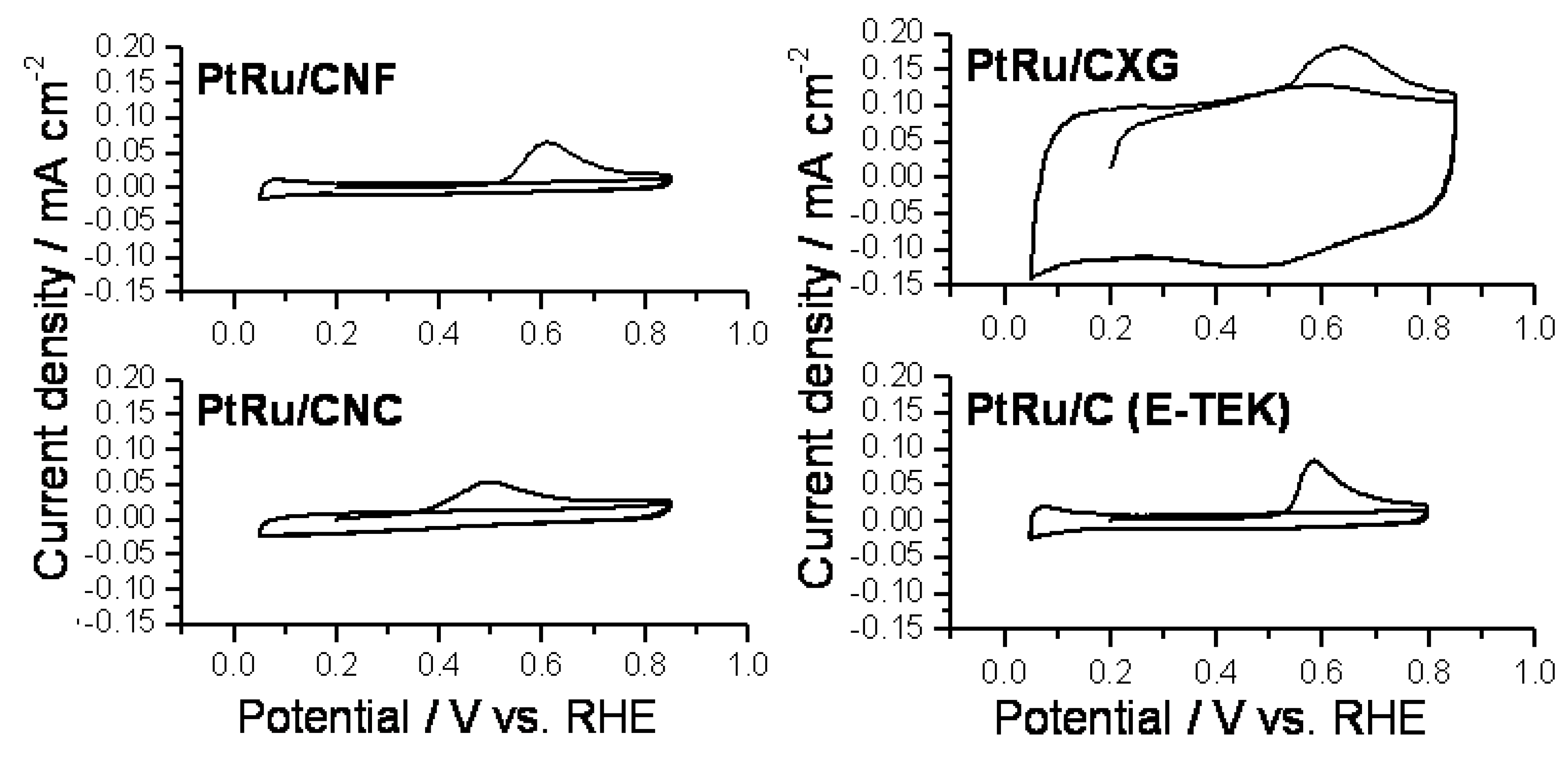
Figure 4. Cyclic voltammograms recorded at 25 °C and 20 mV s−1 during the CO stripping for the PtRu electrocatalysts supported on the different carbon supports.
Catalysts 03 00671 g004
As can be seen, catalysts supported on advanced carbon supports perform higher catalytic activities in comparison to the commercial Pt/C catalyst from ETEK. On the other hand, in terms of stability, highly graphitic supports (CNF and CNC) appear to be slightly more stable in comparison to CXG. The use of advanced carbon supports represents a clear advantage in terms of catalytic activity as Pt supported on these materials is more active towards methanol oxidation than the commertial catalysts. This enhanced effect might be due to either the highly mesoporous structure or the presence of oxygen functionalities in the carbon supports studied, what results specially remarkable in the case of the CXG, whose porous texture is the most developed one. Physico-chemical characterization showed lower metallic crystal sizes for Pt/CNC and Pt/CXG in comparison to Pt/CNF, what results in a higher activity towards methanol electro-oxidation due to a higher intrinsic catalytic activity.
The tolerance towards CO poisoning of the PtRu catalysts supported on the different carbon materials was also evaluated, following the same procedure than for Pt electrocatalysts. The results obtained were graphicated and are shown in Figure 4. With the addition of Ru, the hydride area of the voltammogram decreased and a shift of the oxide stripping peak to more negative potential was produced. The oxidation of CO on the commercial PtRu/C catalyst from E-TEK was found to begin at 0.52 V vs. RHE and showed a current density peak at 0.58 V. For catalysts supported on advanced carbon supports, both the onset and the peak potentials were shifted towards more negative potentials, when compared to the commercial catalyst.
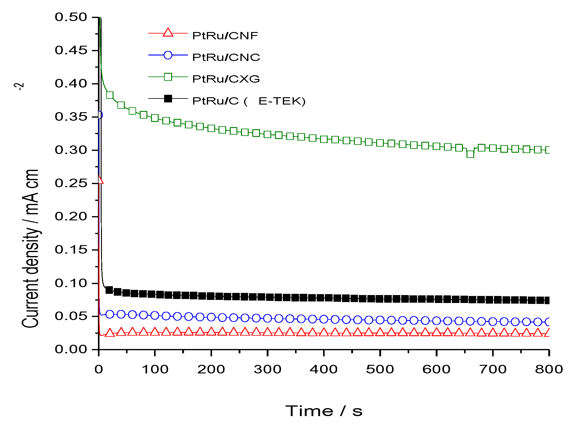
Methanol electrooxidation was also evaluated by chronoamperometry. Figure 5 shows the potentiostatic current densities, normalized by the electroactive surface area, as a function of time. Note that E = 0.5 V for the CNF-based catalyst, while for the rest E = 0.6 V. This is because that was the only experimental data available for comparison. As in the case of Pt, it is not easy to establish a real comparison between the different electrocatalysts synthesized in this work. Nevertheless, it can be affirmed that metal-support interactions produced between the novel carbon materials and the metal nanoparticles improved the methanol oxidation. In spite of this, one can observe the expected and well documented [6,7,8,9,10] increase in the activity due to the presence of Ru, when comparing the results in Figure 3, Figure 5 for Pt/C (ETEK) and PtRu/C (ETEK) catalysts respectively.
Figure 5. Current density-time curves recorded in 2 M methanol + 0.5 M H2SO4 solution at E = 0.60 V vs. RHE for PtRu/CNC, PtRu/CXG and PtRu/C (E-TEK). PtRu/CNF were recorded at E = 0.50 V vs. RHE.
Catalysts 03 00671 g005

3. Experimental Section

3.1. Synthesis of the Carbon Materials

Carbon nanofibers (CNFs) were grown by methane decomposition over a catalyst based on nickel (Ni:Cu:Al2O3), prepared by a co-precipitation method, as described elsewhere [12]. A fixed bed reactor was used in which CNFs were grown for ten hours, an appropriate duration to obtain sufficient amount of deposited carbon without any observed deactivation. The reaction conditions (700 °C and low space velocity) were selected according to previous works [13,14] to obtain highly crystalline CNFs, as will be shown in the results section. The growth process was hourly monitored by analysis of the gases at the outlet of the reactor by gas chromatography. CNFs were treated with a mixture of nitric and sulfuric acids (1:1 v/v) from analytical purity reagents at 65 wt.% and 96 wt.% respectively (Panreac, city, country). The carbonaceous powder was dispersed in the liquid solution and vigorous stirred for 30 min at room temperature. Finally, the CNFs are thoroughly washed with deionized water and dried overnight.
For the synthesis of carbon nanocoils (CNCs), resorcinol-formaldehyde (Sigma-Aldrich, St. Louis, MO, USA) gel was used as the carbon precursor, and nickel(II) nitrate hexahydrate (Panreac, Barcelona, Spain) and cobalt(II) nitrate hexahydrate (Sigma-Aldrich, St. Louis, MO, USA) salts were used as the graphitization catalysts. In addition, silica sol (Supelco, Bellefonte, PA, USA) was used to obtain carbon materials with a high specific surface area and to achieve a good dispersion of the transition-metal nanoparticles [15]. A typical synthesis involves the dissolution of formaldehyde and silica sol in 100 mL of deionized water and the subsequent addition of the nickel-cobalt salts mixture under stirring. Then, resorcinol is added, and the solution is maintained for 0.5 h under stirring conditions. This reaction mixture is subjected to heat treatment at 85 °C for 3 h in a closed system, then opened, and dried at 108 °C. Subsequently, it is carbonized in a nitrogen atmosphere at 900 °C for 3 h using a heating rate of 5 °C/min. The resulting material is washed with a 5 M NaOH (Panreac, Barcelona, Spain) solution for 12 h at 60 °C to remove silica particles, followed by a oxidative purification process with concentrated nitric acid (65 wt%, Panreac, Barcelona, Spain) for 2 h at room temperature to remove the metal salts [16]. This process results in the formation of CNCs.
Carbon xerogels were synthesized following the procedure described in detail in a previous work [17]. Resorcinol, water, formaldehyde and sodium carbonate were mixed using a resorcinol/sodium carbonate (R/C) molar ratio of 800, and stoichiometric resorcinol/formaldehyde molar ratio, i.e., 0.5. After stirring, mixture was poured into closed vials, and left for 24 h at room temperature. Then vials were placed in an oven at 50 °C for 24 h. Finally temperature was risen up to 85 °C and held for 120 h. After ambient drying, pyrolysis of the organic gels was performed in a tubular furnace at 800 °C for 3 h under N2 flow of 100 mL/min. Carbon xerogel was subsequently subjected to oxidation treatment performed at room temperature using concentrated HNO3 (65%) for 120 min.

3.2. Catalysts Preparation

Platinum was deposited on the various supports following an impregnation procedure, the so-called sodium borohydride method [18]. The amount of platinum precursor added was calculated to obtain a load of 20 wt.% Pt/C in the catalyst. An aqueous solution of sodium borohydride (NaBH4, Sigma Aldrich, St. Louis, MO, USA) is used as reduction agent. An aqueous solution of H2PtCl6 3.2 mmol L−1 is prepared from high purity reagent (Sigma Aldrich, St. Louis, MO, USA) and ultrapure water (Millipore Corporation). Firstly the precursor solution is slowly added to a dispersion of carbon in ultrapure water under sonication and, afterwards, the pH of the dispersion is adjusted to 5.0. Then, the sodium borohydride aqueous solution (30 mmol L−1) is dropwise added, maintaining temperature under 18 °C and in the presence of sonication. Subsequently, the catalyst is filtered and thoroughly washed with ultrapure water, and then dried overnight at 60 °C.
PtRu nanoparticles have been deposited on CNFs by a microemulsion route for a total metal concentration of 20 wt.% and a Pt:Ru atomic ratio of 1:1. The synthesis procedure briefly consists on the preparation of a microemulsion composed by 16.5%vol of polyethylene glycol dodecyl ether (Brij 30, Sigma Aldrich, St. Louis, MO, USA), N-heptane and the aqueous solution containing the metal precursors (0.05 M H2PtCl6 and 0.05 M RuCl3), with a ratio of five moles of water per mole of surfactant. The carbonaceous support is dispersed on the microemulsion under sonication, and afterwards the reduction agent (NaBH4) is added under continuous stirring, and left overnight. Subsequently, the catalyst is thoroughly washed with ethanol and water, and dried overnight at 60 °C.
PtRu catalysts were synthesized by impregnation and reduction with formic acid, in the case of using carbon xerogels as supports. The amount of metallic precursor (H2PtCl6 + RuCl3·xH2O) was calculated to obtain a metal loading of 20% w/w. CXG was first dispersed in a 2 M HCOOH solution at 80 °C. Subsequently, an aqueous solution of H2PtCl6 + RuCl3 (Sigma-Aldrich, St. Louis, MO, USA) was added stepwise. Finally catalysts were filtered, thoroughly washed with ultrapure water, and dried overnight at 60 °C.
In the case of CNC as support, PtRu electrocatalysts were prepared using the sodium borohydride reduction method, in the same way than the Pt catalysts.

3.3. Physico-Chemical Characterization

The textural and morphological features of the different carbon supports and catalysts prepared were determined by means of nitrogen physisorption at −196 °C (Micromeritics ASAP 2020) and transmission electron microscopy (TEM, JEOL JEM-2000 FX II). Textural properties such as specific surface area, pore volume and pore size distribution were calculated from each corresponding nitrogen adsorption-desorption isotherms applying the Brunauer-Emmet-Teller (BET) equation, Barrett-Joyner-Halenda (BJH) and t-plot methods.
Surface chemistry of carbon supports was studied by temperature-programmed desorption. Such experiments were performed in a Micromeritics Pulse Chemisorb 2700 equipment, under a flow of helium with a heating rate of 10 °C min−1 from 150 °C up to 1050 °C. The amounts of CO and CO2 desorbed from the samples were analyzed by gas chromatography in a HP 5890 chromatograph with a thermal conductivity detector, packed columns Porapak N 10 ft and molecular sieve.
SEM combined with Energy Dispersive X-Ray Spectroscopy (SEM-EDX, Hitachi S-3400N) was used to determine the amount of metal deposited. An analyzer EDX Röntec XFlash de Si(Li) was employed with this purpose. Catalysts were as well characterized by X-Ray Diffraction (XRD, Bruker), using a Bruker AXS D8 Advance diffractometer, with a a θ-θ configuration and using Cu-Kα radiation. Crystallite sizes were calculated from the Scherrer’s equation on the (220) peak for platinum.
All analysis was carried out at Instituto de Carboquímica (Zaragoza, Spain), except TEM images which were realized at Universidad de Zaragoza (Zaragoza, Spain).

3.4. Electrochemical Characterization and Activity
All the electrochemical experiments were carried out in a conventional half-cell using a three-electrode assembly at room temperature and an Autolab Potentiostat-Galvanostat. A large area pyrolitic graphite rod served as the counter electrode and a reversible hydrogen electrode (RHE) system was used as the reference electrode. All potentials in the text are referred to the latter. The working electrodes were composed of the electrocatalysts deposited as a thin layer over a pyrolitic graphite disk. An aqueous suspension of the catalyst under study was prepared by ultrasonically dispersing it in Nafion and ultrapure water (Milli-Q). An aliquot of 40 µL of the dispersed suspension was pipetted on the top of the pyrolitic carbon disk (7 mm diameter) substrate surface and dried at ambient temperature. After preparation, the electrode was immersed into the deaerated 0.5 M H2SO4 electrolyte, prepared from high purity reagents (Merck) and water purified in a Milli-Q system. The electrolyte was saturated with pure N2 or CO from gas cylinders containing pure gases (99.997% purity, Air Liquide, Madrid, Spain), depending on the experiments.
To characterize the performance of the Pt/C and PtRu/C electrocatalysts, cyclic voltammograms were recorded in the supporting electrolyte solution (0.5 M H2SO4) at a scan rate of 0.02 V s−1. CO stripping voltammograms were obtained after bubbling this gas in the cell for 10 min at 0.20 V vs. RHE, followed by electrolyte exchange and nitrogen purging to remove the excess of CO. The admission potential was selected considering that for this value maximum adsorbate coverage is achieved for CO adsorption on Pt and PtRu. Electrochemical surface active areas were determined from the integration of the CO oxidation region, after correction for double layer capacitance, assuming 420 µC cm−2 involved in the process. All the currents were normalized with respect to the corresponding electrochemical active area. Consequently, the assumed error from the preparation of different catalytic suspensions is avoided.
The electrochemical oxidation of methanol was also studied employing the same system in a 2 M methanol + 0.5 M H2SO4 solution. Cyclic voltammograms and potentiostatic experiments at 0.60 V vs. RHE were recorded in order to evaluate the performance of the electrocatalysts for the oxidation of this compound. All the experiments were conducted at room temperature (25 ± 1 °C).

4. Conclusions

Different advanced carbon supports were synthesized and used as electrocatalyst supports for Pt and PtRu nanoparticles, CNCs, CNFs and CXGs. CNCs and CNFs showed a highly ordered graphitic structure, whereas CXGs presented an amorphous like structure with a highly developed porous structure.
Pt and PtRu-catalysts synthesized were tested towards carbon monoxide and methanol oxidation and compared to the commercially available catalysts from ETEK. Catalysts supported on advanced carbon materials showed improved tolerance towards CO in comparison to ETEK, as well as higher catalytic activity towards methanol electrooxidation, what it may be result of their highly developed porous structure along with a highly ordered graphitic structure.

Acknowledgements

The authors want to thank the Spanish Ministry of Economy and Competitiveness (Secretaría de Estado de I+D+I, previously Spanish Ministry of Science and Innovation) and FEDER for financial support under the project CTQ2011-28913-C02-01 and 02. Verónica Celorrio acknowledges the financial support by CSIC/ESF for her JAE Grant. Sara Pérez Rodríguez acknowledges Gobierno de Aragon for her PhD grant. María Elena Gálvez is indebted as well to the Spanish Ministry of Economy and Competitiveness (Secretaria de Estado de I+D+i) for her “Ramón y Cajal” contract.

Conflicts of Interest

The authors declare no conflict of interest.

References

  1. Aricò, A.S.; Srinivasan, S.; Antonucci, V. DMFCs: From fundamentals aspects to technology development. Fuel Cells 2001, 1, 133–161. [Google Scholar] [CrossRef]
  2. Liu, H.; Song, C.; Zhang, L.; Zhang, J.; Wang, H.; Wilkinson, D.P. A review of anode catalysis in the direct methanol fuel cell. J. Power Sources 2006, 155, 95–110. [Google Scholar] [CrossRef]
  3. Stassi, A.; Gatto, I.; Baglio, V.; Passalacqua, E.; Aricò, A.S. Oxide-supported PtCo alloy catalyst for intermediate temperature polymer electrolyte fuel cells. Appl. Catal. B 2013, 142–143, 15–24. [Google Scholar] [CrossRef]
  4. Zeng, J.; Francia, C.; Gerbaldi, C.; Baglio, V.; Specchia, S.; Aricò, A.S.; Spinelli, P. Hybrid ordered mesoporous carbons doped with tungsten trioxide as supports for Pt electrocatalysts for methanol oxidation reaction. Electrochim. Acta 2013, 94, 80–91. [Google Scholar] [CrossRef]
  5. Acres, G.J.K.; Frost, J.C.; Hards, G.A.; Potter, G.A.; Ralph, T.R.; Thompsett, D.; Burstein, G.T.; Hutchings, G.J. Electrocatalysts for fuel cells. Catal. Today 1997, 38, 393–400. [Google Scholar] [CrossRef]
  6. Sieben, J.M.; Duarte, M.M.E. Methanol, ethanol and ethylene glycol electro-oxidation at Pt and Pt-Ru catalysts electrodeposited over oxidized carbon nanotubes. Int. J. Hydrogen Energy 2012, 37, 9941–9947. [Google Scholar] [CrossRef]
  7. Wang, Z.B.; Yin, G.P.; Zhang, J.; Sun, Y.C.; Shi, P.F. Co-catalytic effect of Ni in the methanol electro-oxidation on Pt-Ru/C catalyst for direct methanol fuel cell. Electrochim. Acta 2006, 51, 5691–5697. [Google Scholar] [CrossRef]
  8. Liu, Z.; Ling, X.Y.; Su, X.; Lee, J.Y. Carbon-supported Pt and PtRu nanoparticles as catalysts for a direct methanol fuel cell. J. Phys. Chem. B 2004, 108, 8234–8240. [Google Scholar] [CrossRef]
  9. Chang, W.-C.; Nguyen, M.T. Investigations of a platinum–ruthenium/carbon nanotube catalyst formed by a two-step spontaneous deposition method. J. Power Sources 2011, 196, 5811–5816. [Google Scholar] [CrossRef]
  10. Tsuji, M.; Kubokawa, M.; Yano, R.; Miyamae, N.; Tsuji, T.; Jun, M.S.; Hong, S.; Lim, S.; Yoon, S.H.; Mochida, I. Fast preparation of PtRu catalysts supported on carbon nanofibers by the microwave-polyol method and their application to fuel cells. Langmuir 2007, 23, 387–390. [Google Scholar] [CrossRef]
  11. Lázaro, M.J.; Celorrio, V.; Calvillo, L.; Pastor, E.; Moliner, R. Influence of the synthesis method on the properties of Pt catalysts supported on carbon nanocoils for ethanol oxidation. J. Power Sources 2011, 196, 4236–4241. [Google Scholar] [CrossRef]
  12. Suelves, I.; Lázaro, M.J.; Moliner, R.; Echegoyen, Y.; Palacios, J.M. Characterization of NiAl and NiCuAl catalysts prepared by different methods for hydrogen production by thermo catalytic decomposition of methane. Catal. Today 2006, 116, 271–280. [Google Scholar] [CrossRef]
  13. Lázaro, M.J.; Sebastián, D.; Suelves, I.; Moliner, R. Carbon nanofiber growth optimization for their use as electrocatalyst support in proton exchange membrane (PEM) fuel cells. J. Nanosci. Nanotechnol. 2009, 9, 4353–4359. [Google Scholar] [CrossRef]
  14. Sebastián, D.; Calderón, J.C.; González-Expósito, J.A.; Pastor, E.; Martínez-Huerta, M.V.; Suelves, I.; Moliner, R.; Lázaro, M.J. Influence of carbon nanofibers properties as electrocatalyst support on the electrochemical performance for PEM fuel cells. Int. J. Hydrogen Energy 2010, 35, 9934–9942. [Google Scholar] [CrossRef]
  15. Celorrio, V.; Calvillo, L.; Martínez-Huerta, M.V.; Moliner, R.; Lázaro, M.J. Study of the Synthesis Conditions of Carbon Nanocoils for Energetic Applications. Energy Fuels 2010, 24, 3361–3365. [Google Scholar] [CrossRef]
  16. Celorrio, V.; Calvillo, L.; Pérez-Rodríguez, S.; Lázaro, M.J.; Moliner, R. Modification of the properties of carbon nanocoils by different treatments in liquid phase. Micropor. Mesopor. Mat. 2011, 142, 55–61. [Google Scholar] [CrossRef]
  17. Alegre, C.; Gálvez, M.E.; Baquedano, E.; Pastor, E.; Moliner, R.; Lázaro, M.J. Influence of support’s oxygen functionalization on the activity of Pt/Carbon xerogels catalysts for methanol electro-oxidation. Int. J. Hydrogen Energy 2012, 37, 7180–7191. [Google Scholar] [CrossRef]
  18. Salgado, J.R.C.; Antolini, E.; González, E.R. Structure and activity of carbon-supported Pt−Co electrocatalysts for oxygen reduction. J. Phys. Chem. B 2004, 108, 17767–17774. [Google Scholar] [CrossRef]