Article

Al2O3@SiO2 Supported NiMo Catalyst with Hierarchical Meso-Macroporous Structure for Hydrodemetallization

1
National Engineering Laboratory for Green Chemical Productions of Alcohols-Ethers-Esters, College of Chemistry and Chemical Engineering, Xiamen University, Xiamen 361005, China
2
SINOPEC Research Institute of Petroleum Processing Co., Ltd., Beijing 100083, China
*
Authors to whom correspondence should be addressed.
These authors contributed equally to this work.
Catalysts 2025, 15(7), 646; https://doi.org/10.3390/catal15070646
Submission received: 8 June 2025 / Revised: 26 June 2025 / Accepted: 29 June 2025 / Published: 1 July 2025

Abstract

The pore structure of a hydrotreating catalyst plays a pivotal role in hydrodemetallization (HDM) reactions. To effectively construct a meso-macroporous catalyst, we employed a CTAB-guided in situ TEOS hydrolysis approach to prepare silica-coated γ-Al2O3@SiO2 composite supports. The silica shell incorporation significantly enhances specific surface area and reduces the metal–support interactions, thereby improving the dispersion of NiMo active components and boosting the deposition of metal impurity. Hence, the NiMo/Al2O3@SiO2 catalyst (2.8 wt.% NiO, 4.3 wt.% MoO3) exhibits much higher HDM activity than that of NiMo/Al2O3. This is evidenced by markedly higher demetallization rate constant (1.38 h−1) and turnover frequency (0.56 h−1) of the NiMo/Al2O3@SiO2. The NiMo/Al2O3@SiO2 catalyst further demonstrates excellent recyclability during sequential HDM reactions. This superior catalytic behavior stems from the hierarchical meso-macroporous structure, which simultaneously facilitates the deposition of metal impurities and mitigates deactivation by pore blockage.

Graphical Abstract

1. Introduction

Increasingly stringent environmental regulations [1,2,3] and substantial metal content in crude oil [4,5,6] have triggered the development of efficient hydrotreating catalysts for petroleum refining. In large-scale industrial applications, the catalytic hydrodemetallization (HDM) process is regarded as the most effective method for addressing metal contaminants in crude oil. Over several decades, extensive research efforts have been dedicated to enhancing the intrinsic catalytic activities of conventional Co(Ni)Mo(W) catalysts employed in HDM processes [7,8]. However, HDM catalysts typically face significant deactivation issues due to deposited metals (primarily Ni and V), which obstruct active surface sites or block pores within the catalysts [9,10,11]. Consequently, developing high-capacity metal deposition and highly active catalysts for heavy residual oil HDM has emerged as one of the most pressing challenges.
Mo-based supported catalysts have long been among the most widely utilized options for residue hydrotreating [12]. Previous studies have primarily focused on catalyst supports, emphasizing that pore structure plays a critical role. Kohli et al. [13] investigated the influence of different supports (SBA-15, activated carbon, mesoporous Al2O3) on catalytic HDM activity, indicating that the NiMo/Al2O3 catalyst exhibited superior performance owing to its larger pore volume and higher dispersion of active metals. It was shown that numerous macropores within the support alleviated diffusion limitations and enhanced the accessibility of inner active sites for large residue molecules. To create more applicable catalysts for HDM processes, meso-macroporous alumina supports were developed recently. Mohan et al. [14] combined peptized alumina with activated carbon to fabricate a carbon–alumina composite support featuring meso-macropores generated through partial calcination of activated carbon. The residual carbon within this support exhibited significant adsorption capacity for metal porphyrins, thereby substantially reducing metal deposition on catalytic active sites and improving catalyst stability. Moreover, employing mechanical mixing techniques with various materials—such as combining alumina with nano-sized zeolite Y [15] or activated carbon [16]—allows adjustment of porous structures by controlling material mixing ratios based on differing pore characteristics. However, achieving uniform pore distribution at a microscopic scale via mechanical mixing remains challenging; there still exist the issues of insufficient contact between large reactant molecules and inner sites.
To address these challenges, our previous work [17] synthesized nest-like Al2O3 hollow spheres composed of nanowires with bimodal-type meso-macroporosity. The resulting NiMo/nest-like Al2O3 catalyst displayed markedly improved HDM activity and enhanced stability compared to NiMo/commercial Al2O3, which was attributed to its open pore structure. Accordingly, a suitable pore structure including some macropores for mass transfer and abundant mesopores to distribute catalytic active sites was required for the efficient HDM catalyst. In this work, SiO2-coated Al2O3 supports featuring hierarchical meso-macroporous structures were prepared to precisely control specific surface area and pore distribution. The physicochemical properties of synthesized NiMo/Al2O3@SiO2 catalysts were systematically characterized, with particular focus on how synthesis conditions affect SiO2 and Al2O3 species during preparation processes. The optimized NiMo/Al2O3@SiO2 exhibited exceptional HDM performance for both Ni-TPP substrates and bimetallic systems (NiFe and NiV), which could be ascribed to the meso-macroporous structure coupled with an expansive surface area afforded by SiO2 coating.

2. Results

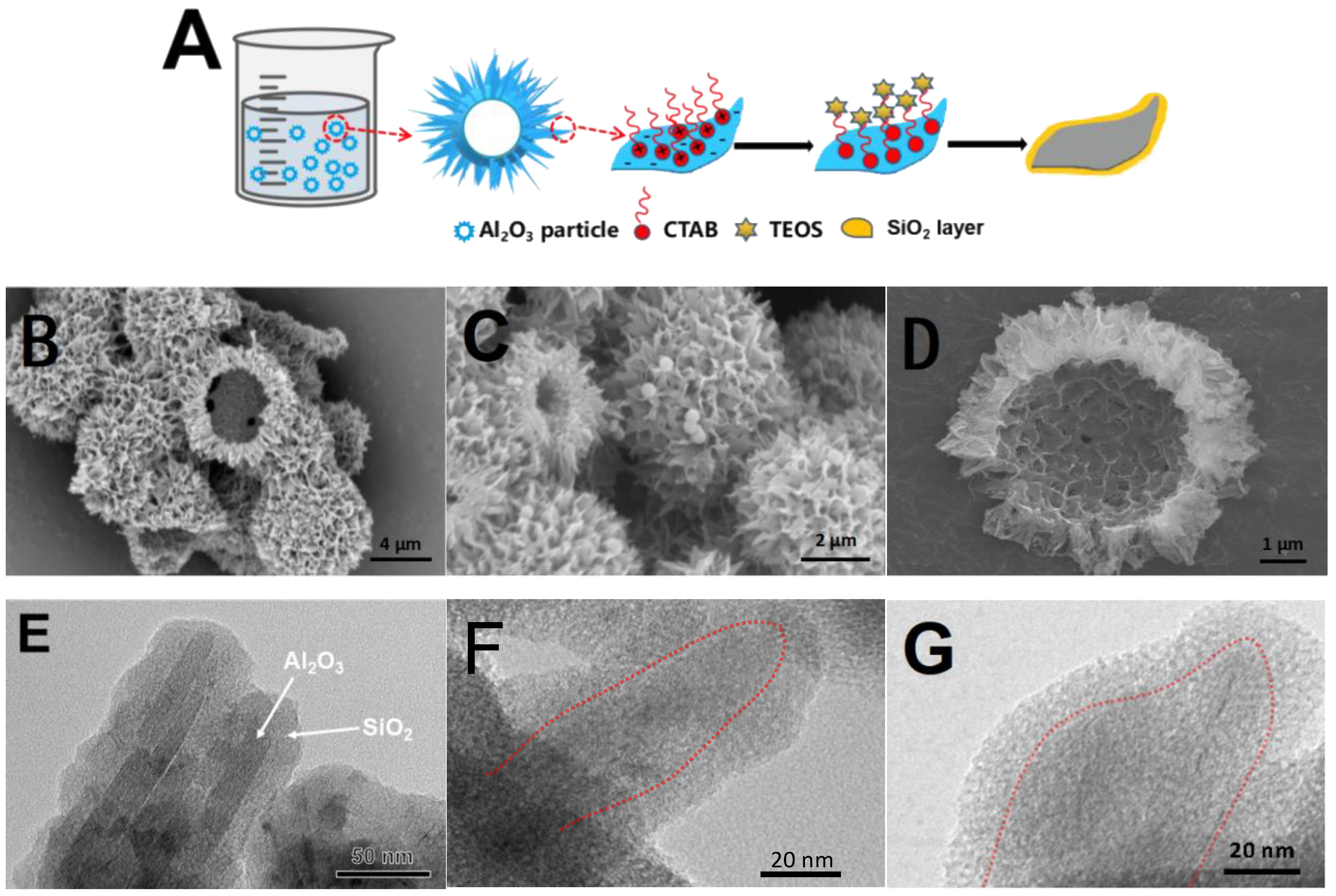
2.1. Morphology and Structure of Al2O3@SiO2

The synthesis route for Al2O3@SiO2, achieved through the in situ coating of alumina particles with a silicon-based precursor, was illustrated in Figure 1A. In an alkaline ethanol solution, CTAB was adsorbed onto the Al2O3 surface as a structural guiding agent, facilitating the hydrolysis of TEOS on the Al2O3 surface and leading to the formation of a mesoporous silica coating layer. Followed by separation, drying, and calcination processes, the silica-coated Al2O3@SiO2 support was obtained. During the coating process, self-aggregation of the precursor resulted in amorphous silica microparticles forming on the surface, which was a competitive reaction. SEM images depicting both Al2O3 and Al2O3@SiO2 were presented in Figure 1B–D, revealing that both supports exhibited nest-like morphology with pronounced macropores. Aside from a few silica spheres present on the surface of Al2O3@SiO2, its morphology and structure showed no significant alteration compared to that of pure Al2O3. TEM images of Al2O3@SiO2 in Figure 1E–G confirmed the successful SiO2 layer deposition on the surface of Al2O3, as indicated by alumina within dotted lines and silica coating outside them.
Water–ethanol solution utilized in this synthetic system played a pivotal role in regulating the thickness and quality of the silica coating layer [18]. To optimize the water–ethanol solution, the volume ratio of water/ethanol (W/E) was varied from 0.75 to 2.50. SEM images illustrating various synthesized Al2O3@SiO2 under different W/E ratios were displayed in Figure 2. At high ethanol content (W/E = 0.75), encapsulation efficiency deteriorated significantly due to excess ethanol inhibiting TEOS hydrolysis, resulting in inadequate silica coverage incapable of forming a complete coating layer over alumina. Conversely, at a low ethanol concentration (W/E = 2.5), we observed that during mixture separation, it produced suspensions rather than clear filtrates. SEM images captured from both precipitated solids and centrifuged suspensions were depicted respectively as Figure 2C,D. Notably, no visible silica spheres were detected upon examining alumina surfaces in Figure 2C, whereas substantial silica spheres appeared in centrifuged suspensions, as seen in Figure 2D. It has been suggested that CTAB micelles formed within solution interiors where TEOS underwent hydrolysis, resulting in spherical silicas; furthermore, decreasing levels led towards increased critical micelle concentration of CTAB [19]. Combined with the pore size distribution (Figure S1), an increase in W/E (W/E > 1.33) would lead to the mesopores constructed by the silica spheres due to the change in CTAB micelle concentration, which suggests a poor coating effect. We observed a much larger pore size for the Al2O3@SiO2 catalysts with a higher W/E ratio, especially for the sample with W/E = 2.5. According to the texture properties and HDM performances of the catalysts synthesized with different W/E (Table S1), an appropriate aqueous ethanol solution was an indispensable condition for synthesizing efficient Al2O3@SiO2.
Ammonia concentration is also a crucial factor influencing the synthesis of Al2O3@SiO2. SEM images of the Al2O3@SiO2 synthesized with an ammonia concentration of 0.1~0.4 M are shown in Figure 3. When the pH of the solution exceeded the low isoelectric point (IEP) of alumina (at about 8), higher ammonia concentration increased the negative potential on the surface of alumina [20], thereby promoting the adsorption of the CTA+ precursor alongside enhancing the hydrolysis of TEOS and thus leading to the formation of coating silica layer [21]. However, excessive ammonia concentration would lead to more silica microparticles agglomeration into spheres, as shown in Figure 3C,D. An increase in ammonia concentration from 0.1 M to 0.4 M notably reduced the number of 2~4 nm mesopores in the Al2O3@SiO2 (Figure S2) and diminished the specific surface area (Table S2).
Pore size distribution analysis indicated a bimodal pore size distribution centered respectively at around 3 nm and 45 nm for all the supports synthesized with different water/ethanol ratios and different ammonia concentrations (Figures S1 and S2). Indeed, narrow pore width distributions at 2~4 nm were obtained. The different pore widths for these materials were most likely caused by the influences of the concentration-induced micelle separation on the gelation process in the Al2O3@SiO2. Therefore, Al2O3@SiO2 synthesized under the conditions of water/ethanol ratio of 1.33 and ammonia concentration of 0.2 M showed a complete silica coating layer with high specific surface area and exhibited a high catalytic activity in HDM of metal–organic compounds. The numerous meso-macropores within the support alleviated diffusion limitations and enhanced the accessibility of inner active sites for large residue molecules.

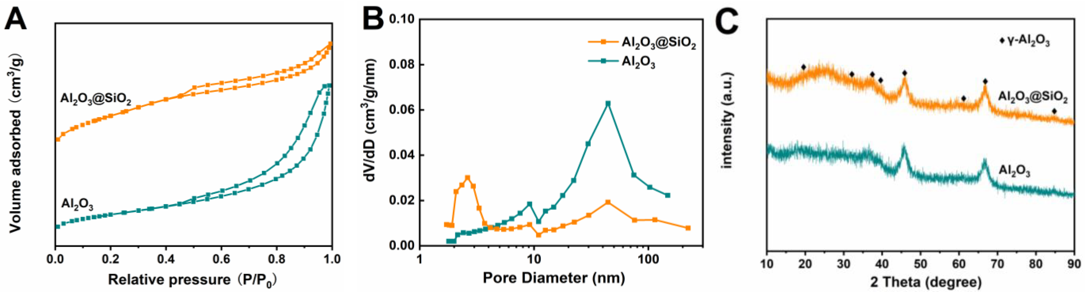
2.2. Physical Properties of Al2O3@SiO2

Under the optimum conditions of W/E = 1.33 and ammonia concentration of 0.2 M, the optimal Al2O3@SiO2 was prepared and compared with the pure Al2O3 support. To further understand the physical characteristics of the supports, BET analysis was conducted and is shown in Figure 4A. It could be seen obviously that the Al2O3 and Al2O3@SiO2 exhibited typical type II isotherms, indicating the presence of large mesopores or macropores [22]. However, the isotherm of Al2O3@SiO2 became smooth at high pressure (P/P0 > 0.8) and turned steeper at medium pressure (0.3 > P/P0 > 0.5), due to the occupation of some macropores by mesoporous silica. Owing to the substantial presence of mesopores within the silica layer, the specific surface area of the Al2O3@SiO2 was 405 m2·g−1, significantly higher than that of the Al2O3 (200 m2·g−1).
To further elucidate the pore structure of the supports, the mesoporous pore size distribution was analyzed by the BJH method, as presented in Figure 4B. The pore size distribution for Al2O3 centered around 9 nm and 45 nm, while the large mesopores were probably caused by the stack gaps between alumina nanowires [16], resulting in a total pore volume of 0.44 cm3·g−1. In contrast, for the Al2O3@SiO2, the peak corresponding to a pore size of 45 nm was diminished, indicating a reduction in large mesopore proportions. However, numerous mesopores ranging from 2 to 4 nm were observed on Al2O3@SiO2 with a total pore volume of 0.33 cm3·g−1, which also indicated that some large mesopores were occupied by a silica layer. XRD patterns of the supports in Figure 4C illustrated that no diffraction peaks associated with silica species were detected within the pattern for Al2O3@SiO2, indicating that the silica layer on the surface was amorphous. Both diffraction patterns displayed peaks at 19.8°, 37.5°, 39.4°, 46.2°, 66.8°, and 84.8°, which could correspond to γ-Al2O3.

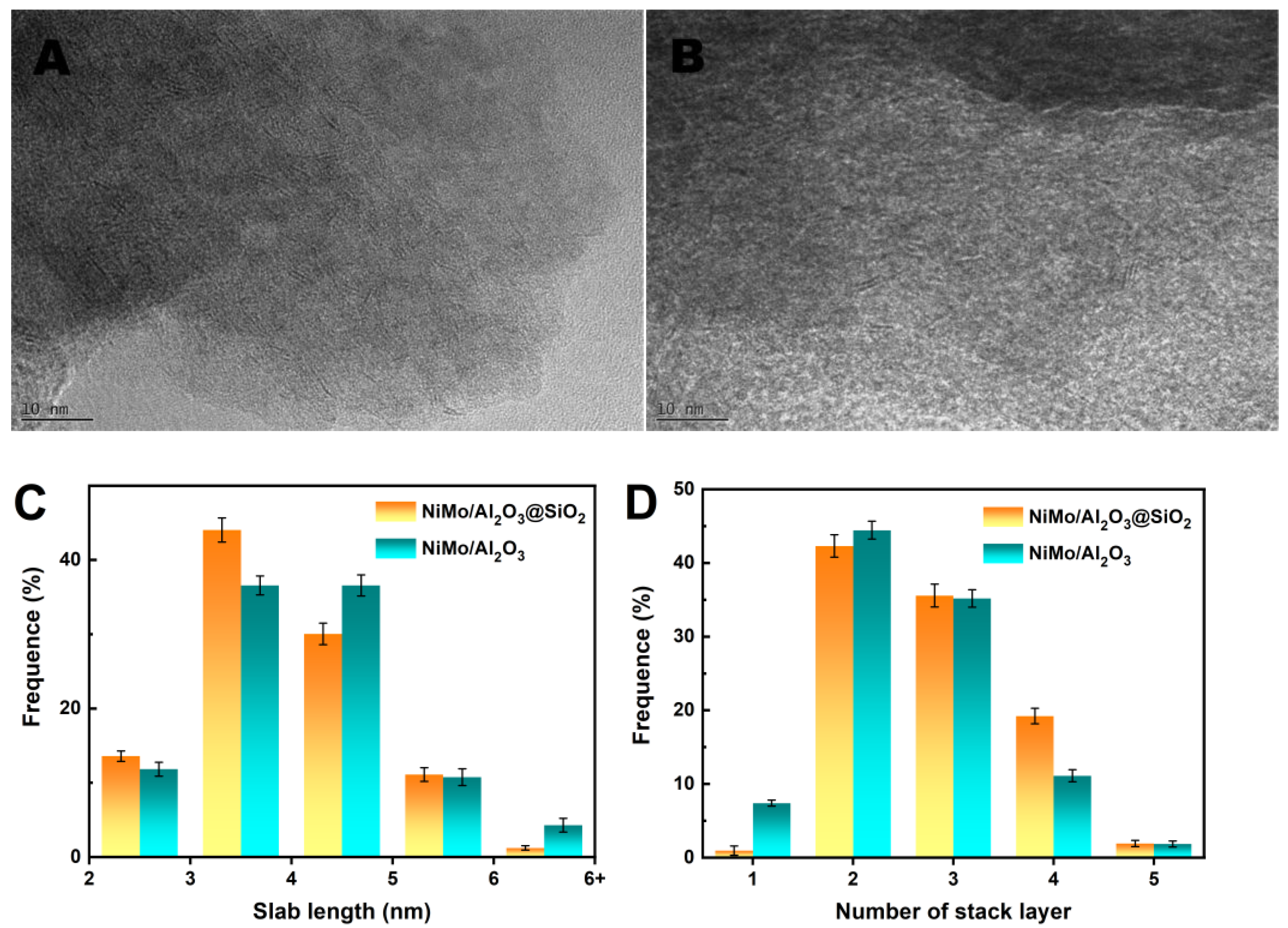
2.3. Physicochemical Properties of NiMo/Al2O3@SiO2 Catalyst

The as-prepared Al2O3@SiO2 and Al2O3 were used as supports for NiMo catalysts with a loading of 3.0 wt.% NiO and 4.5 wt.% MoO3. The components of the catalysts were measured by XRF, as shown in Table 1. It can be noted that the measured contents of active components closely aligned with theoretical expectations. Inductively coupled plasma-mass spectrometry (ICP-MS) analysis revealed that the Ni and Mo contents on the NiMo/Al2O3@SiO2 catalyst were 2.18 and 2.76 wt%, respectively (Table S3). The NiMo/Al2O3 catalyst exhibited similar Ni and Mo contents, which were consistent with the XRF results. XRD patterns of the NiMo/Al2O3 and NiMo/Al2O3@SiO2 catalysts in Figure 5A revealed similar diffraction patterns. There was no peak corresponding to crystalline NiMo oxides, which indicated that Ni and Mo species were well dispersed over the supports. Typical properties of the supported NiMo catalysts are listed in Table 1.
To investigate the influence of the silica coating layer on the interaction between NiMo oxides and support in the catalyst, H2-TPR was conducted as shown in Figure 5B. A main reduction peak emerged prominently in the temperature range of 400 °C to 520 °C, which could be attributed to the partial reduction of Mo6+ to Mo4+ of amorphous Mo oxides [23]. Compared to NiMo/Al2O3, the reduction peak of NiMo/Al2O3@SiO2 shifted to a lower temperature (approximately 452 °C), which could be attributed to the weak interaction between silica and Mo species [24]. Conversely, a shoulder peak around 650 °C appeared on the NiMo/Al2O3@SiO2 catalyst, which could be caused by the minimal amount of MoO3 aggregation [25].
Mo 3d and Ni 2p XPS spectra of the sulfided catalysts are shown in Figure 6, and the fitting results are listed in Table S4 and Table S5, respectively. Molybdenum existed as disulfide MoS2 (MoIV, locating at 227.9 ± 0.1 eV), Mo oxide species (MoVI, locating at 232.0 ± 0.1 eV), and an intermediate state of Mo oxysulfide (MoV, locating at 230.6 ± 0.1 eV) [26,27]. For the NiMo/Al2O3@SiO2 catalyst, the percentage of MoIV species was higher than that of NiMo/Al2O3, which could be attributed to weaker Mo-silica interaction [28]. Furthermore, a broad peak at approximately 225.2 eV was assigned to the S 2s of MoS2. These results indicated that silica layers on the NiMo/Al2O3@SiO2 facilitated the reduction and sulfidation of Mo species, consistent with the H2-TPR experiments. In the Ni 2p XPS spectra, it could be observed that the Ni 2p binding energy (BE) of 853.1 eV ± 0.1 eV corresponded to the Ni in Ni-Mo-S phase [29,30], while the peak at 856.0 eV was ascribed to Ni(II), indicating the presence of a small amount of NiO phase. The remaining two broad peaks in the spectra were identified as satellite lines of the corresponding Ni species. Both catalysts exhibited a similar percentage of NiMoS phase (>80%), indicating that nickel species were well sulfided on the catalysts [31].
Figure 7 shows the HRTEM images of both sulfided catalysts and their corresponding MoS2 length distribution and stacking layer number distribution. Typical MoS2 black thread-like fringes with an interplanar distance of 6.2 Å were observed in both the sulfided NiMo/Al2O3@SiO2 and NiMo/Al2O3 catalysts [32]. In order to make quantitative analysis, images containing 300–400 MoS2 slabs from at least 20 different parts of the sulfided catalysts were counted, and the statistical results of MoS2 slab lengths and stacking layer numbers are shown in Figure 7C,D. Accordingly, the average slab length (LMoS) and the average stacking number (NMoS) of the catalyst were obtained; the proportion of Mo atoms on the surface of MoS2 slabs to total Mo atoms (fMo) was also calculated [33,34], as shown in Table 1. The well-stacked layered structure of MoS2 on NiMo/Al2O3@SiO2 consisted of 2–4 stacking layers with an average length of 3.9 nm, and the calculated fMo was 0.27. In contrast, the NiMo/Al2O3 consisted of randomly oriented several layers with an average length of 4.1 nm, and the fMo was calculated as 0.26. Ni-Mo-S active sites were mainly located at the edges and corners of the MoS2 slabs [35]. Both catalysts exhibited short MoS2 crystallite lengths and fewer stacking layers, resulting in a considerable number of active sites for HDM reaction [36].

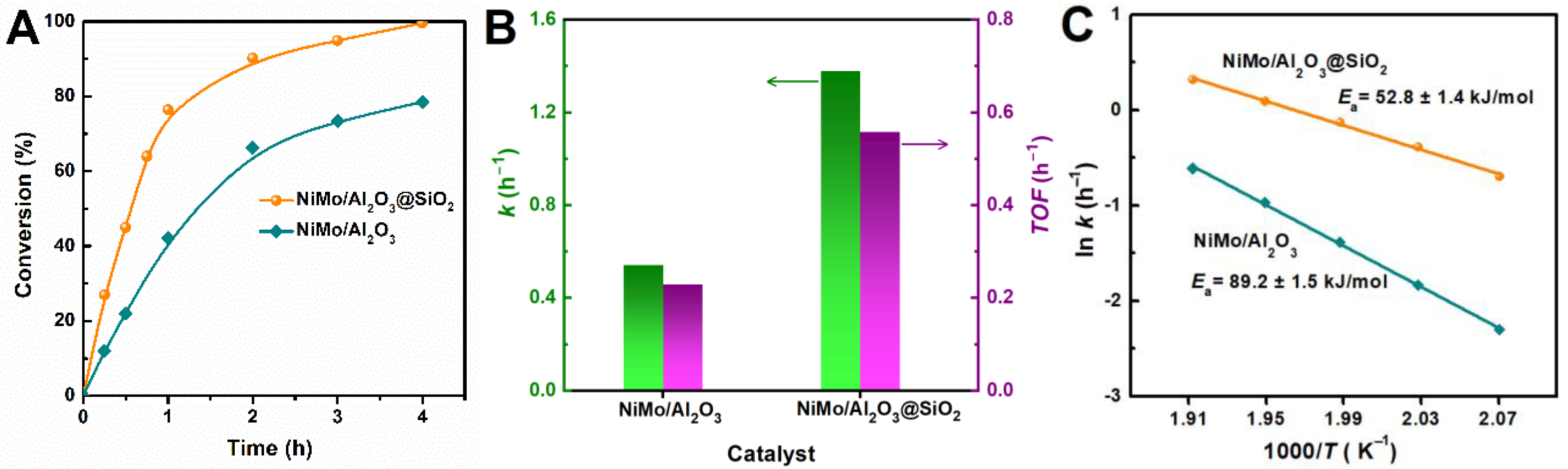
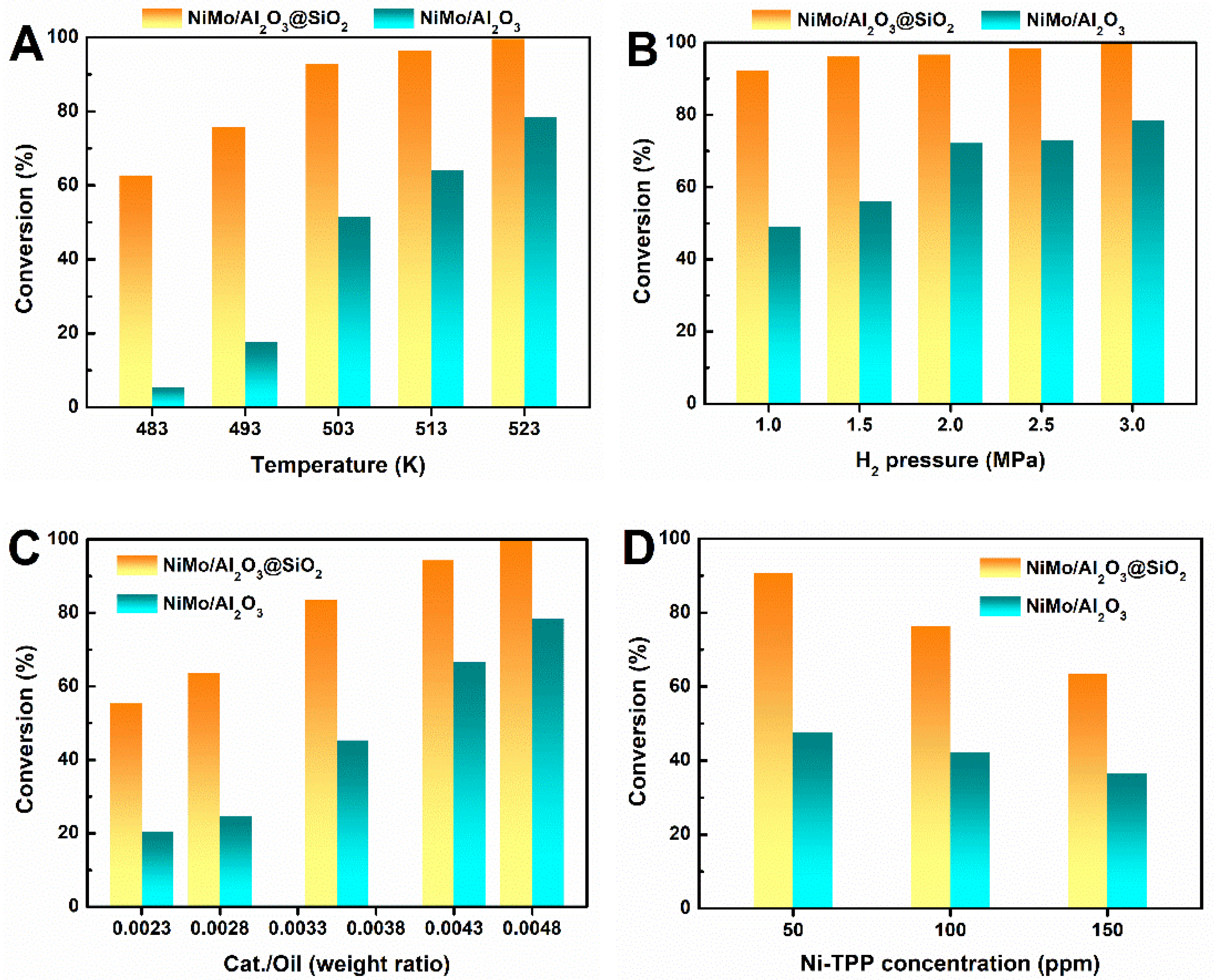
2.4. HDM Performance of NiMo/Al2O3@SiO2 Catalyst

To evaluate the catalytic performance of the as-prepared NiMo/Al2O3@SiO2 and NiMo/Al2O3 catalysts, HDM of nickel (II) 5, 10, 15, 20-tetraphenylporphine (Ni-TPP) was chosen as a probe reaction, which was carried out at 523 K under 3 MPa H2 in a Teflon-lined stainless-steel autoclave. As illustrated in Figure 8A, the NiMo/Al2O3@SiO2 catalyst exhibited significantly enhanced HDM activity compared to that of NiMo/Al2O3. Notably, completely conversion of Ni-TPP was achieved over NiMo/Al2O3@SiO2 within 4 h. Conversely, only 78% demetallization conversion was observed for NiMo/Al2O3 under identical conditions. Additionally, both Al2O3@SiO2 and Al2O3 supports exhibited no activity in the HDM reaction, suggesting that metal sulfide served as an active species in both NiMo/Al2O3@SiO2 and NiMo/Al2O3 catalysts. Additionally, the demetallization rate constant on NiMo/Al2O3@SiO2 was calculated to be 1.38 h−1, approximately 2.5 times higher than that for NiMo/Al2O3 (0.54 h−1). The turnover frequency (TOF) of NiMo/Al2O3@SiO2 catalyst (0.56 h−1) was also found to be markedly higher than that of NiMo/Al2O3 catalyst (0.23 h−1), with calculations based on Ni-TPP conversion below 50%. Such pronounced HDM activity presented by the NiMo/Al2O3@SiO2 catalyst underscored the advantages of hierarchical porosity and larger specific surface area provided by silica-coated alumina for effective metal deposition. To further elucidate differences in catalytic performance between NiMo/Al2O3@SiO2 and NiMo/Al2O3, apparent activation energy (Ea) was calculated using the Arrhenius equation based on the kinetic results from the HDM reaction. Ea for NiMo/Al2O3@SiO2 was determined to be approximately 52.8 kJ·mol−1, significantly lower than that for NiMo/Al2O3 (89.2 kJ·mol−1). This reduced activation energy resulted from accessibility and efficient anchoring of Ni-TPP molecules on NiMoS sites in silica-shell pores, facilitating the activation of Ni-TPP to promote the HDM reaction.
Hh−1To comprehensively evaluate the catalytic performance, a series of Ni-TPP HDM tests were conducted under varying conditions over NiMo/Al2O3@SiO2 and NiMo/Al2O3 catalysts. Figure 9A illustrates the influence of reaction temperature on the catalytic performance at a hydrogen pressure of 3 MPa for 4 h. Elevating the reaction temperature significantly enhanced Ni-TPP conversion for both NiMo/Al2O3@SiO2 and NiMo/Al2O3. Specifically, Ni-TPP conversion over NiMo/Al2O3 greatly increased from 5% at 483 K to 78% at 523 K. An increase in H2 pressure was observed to slightly improve HDM activity. A high demetallization conversion exceeding 92% was achieved on NiMo/Al2O3@SiO2 within a H2 pressure range of 1.0 MPa to 3.0 MPa, whereas the conversion remained below 79% for NiMo/Al2O3. Furthermore, increasing the catalyst/oil weight ratio from 0.0023 to 0.0048 led to an enhancement in Ni-TPP conversion from 55% to nearly complete conversion (>99%) over NiMo/Al2O3@SiO2 (Figure 9C). In contrast, Ni-TPP conversion on NiMo/Al2O3 catalyst only increased from 20% to 78%. The effect of Ni-TPP concentration on the HDM reaction was also investigated (Figure 9D). It was observed that Ni-TPP conversion on NiMo/Al2O3@SiO2 consistently surpassed that on NiMo/Al2O3 in the 50–150 ppm Ni-TPP solution. The HDM reactions were obviously influenced by Ni-TPP concentration, especially at high conversion levels.
Bimetallic substrates (Ni-Fe and Ni-V) were also employed to examine the demetallization activity, as depicted in Figure 10A. It was noteworthy that high demetallization activity was observed for Fe-TPP using both catalysts. Conversely, Ni-TPP proved to be significantly more challenging to demetallize. Compared to NiMo/Al2O3, NiMo/Al2O3@SiO2 exhibited remarkable demetallization activity toward both NiFe and NiV bimetallic substrates. For the NiMo/Al2O3@SiO2 catalyst, higher Ni-TPP and V-TPP conversions were achieved in the presence of bimetallic substrates. The enhanced demetallization activity was attributed to the distinctive structure of NiMo/Al2O3@SiO2 catalyst, where the SiO2 coating layer provided a high specific surface area and abundant mesoporous pores for depositing metal impurities. We further evaluated the stability and recyclability of the NiMo/Al2O3@SiO2 and NiMo/Al2O3 catalysts for Ni-TPP HDM. As revealed in Figure 10B, no obvious conversion loss was observed. For the NiMo/Al2O3@SiO2 catalyst, the HDM conversion of Ni-TPP remained above 95% with stable activity over eight successive runs. High-resolution TEM image of spent NiMo/Al2O3@SiO2 catalyst showed the characteristic MoS2 fringe structures (0.62 nm interlayer spacing), no significant sintering or MoS2 stacking alteration was observed, which confirmed the structural integrity of MoS2 over NiMo/Al2O3@SiO2 catalyst after reaction cycles. The excellent recyclability further suggested the advantage of the hierarchical pore structure provided by the SiO2 coating, which allowed the NiMo/Al2O3@SiO2 to alleviate the blocking of the catalyst pore caused by metal deposition. This robust catalyst, synthesized using a common method and low-cost chemical precursors, would reduce catalyst replacement frequency in industrial scale-up applications, delivering significant economic and environmental benefits.

3. Materials and Methods

3.1. Synthesis

3.1.1. Chemicals and Materials

Nickel-5, 10, 15, 20-tetraphenylporphyrin (Ni-TPP), hexadecyl trimethyl ammonium bromide (CTAB) was purchased from Sigma-Aldrich Co., Ltd. Liquid paraffin (0.85 g/mL) and concentrated ammonia (NH3·H2O, 25 wt.%~28 wt.%) were purchased from National Medicine Group Chemical Reagent Co., Ltd. Aluminum sulfate (Al2(SO4)3·18H2O), urea, ethanol absolute (C2H5OH), tetraethyl orthosilicate (TEOS), carbon disulfide (CS2), nickel nitrate (Ni(NO3)2·6H2O) and ammonium molybdate ((NH4)6Mo7O24·4H2O) were analytical grade and purchased from National Medicine Group Chemical Reagent Co., Ltd. All reagents were used without further purification.

3.1.2. Preparation of γ-Al2O3 Supports

Alumina (Al2O3) was prepared following a method similar to a previous report [16]. Typically, 1.80 g aluminum sulfate and 0.42 g urea were dissolved in 70 mL deionized water. After being transferred into a 100 mL hydrothermal reactor with a Teflon liner, the mixture was maintained at 180 °C for 4 h and then cooled naturally to room temperature. The white precipitate was filtered, washed repeatedly with water and ethanol, and finally dried at 110 °C for 12 h, and calcined at 550 °C in flowing air for 4 h to obtain the Al2O3.

3.1.3. Preparation of Al2O3@SiO2 Supports

SiO2-coated γ-Al2O3 supports (Al2O3@SiO2) were obtained based on the modified Stöber synthesis. Typically, 0.20 g Al2O3 and 1.00 g CTAB were dispersed into 280 mL water/ethanol solution with a volume ratio (W/E) of 1.33, and then concentrated ammonia was added to the mixtures and stirred for 30 min (total concentration of ammonia, 0.2 M). Subsequently, 0.35 g TEOS was added, and the mixtures were kept stirring for 12 h at 30 °C. The solids were obtained by filtration, washed with water and ethanol, and dried at 110 °C for 12 h, then calcined at 550 °C in flowing air for 4 h to obtain the Al2O3@SiO2. Similar experiments were also conducted with W/E ratios varying from 0.75 to 2.50, and different concentrations of ammonia from 0.05 M to 0.20 M to understand the formation mechanism of the Al2O3@SiO2.

3.1.4. Preparation of Al2O3 and Al2O3@SiO2 Supported NiMo Catalysts

Al2O3 and Al2O3@SiO2 supported NiMo catalysts were prepared via the co-impregnation method. Typically, quantitative (NH4)6Mo7O24·4H2O and Ni(NO3)2·6H2O were dissolved in deionized water at room temperature, followed by the addition of the support. After being dried at 110 °C for 12 h and calcined at 550 °C for 4 h, the NiMo/Al2O3@SiO2 and NiMo/Al2O3 catalysts were obtained. Theoretical loadings of NiO and MoO3 for the catalysts were controlled to be 3.0 wt.% and 4.5 wt.%, respectively.

3.2. Characterization

The morphology was observed by scanning electron microscope (SEM) performed on a Zeiss Sigma SEM microscope operating at 5–15 kV. The microstructure was studied by a high-resolution transmission electron microscopy (F20 HRTEM) with an accelerating voltage of 200 kV. X-ray powder diffraction (XRD), a Japan Rigaku Ultima IV X-ray diffractometer (40 kV, 30 mA) equipped with graphite monochromatized Cu-Kα radiation (λ = 0.15406 nm), was used to characterize the crystal structure, with a scanning speed of 20°/minute. A Micromeritics ASAP 3020 nitrogen adsorption apparatus (US) was used to measure nitrogen adsorption isotherms at the temperature of liquid N2 with N2 pressures (P/Po) ranging from 0 to 1.0. Surface area was calculated according to Brunauer–Emmett–Teller (BET) method and the pore size distribution was obtained according to the Barret–Joyner–Halenda (BJH) method. A Bruker AXS S8 TIGER X-ray fluorescence (XRF) analyzer and inductively coupled plasma-mass spectrometry (ICP-MS, Agilent7700) were adopted to measure the element content of the catalyst.
Temperature-programmed reduction (TPR) analyses of the oxidic catalysts were performed on a homemade apparatus. The sample was heated to 700 °C at a rate of 10 °C/min under 5% H2/Ar flow (40 mL/min). H2 consumption was detected by a thermal conductivity detector (TCD). X-ray photoelectron spectroscopy (XPS) measurements of the sulfided catalysts were taken on a Thermo Scientific ESCALAB Xi+ spectrometer with Mg Kα radiation under vacuum (<10−9 mbar). Prior to testing, the oxide catalysts were sulfided in a 15% H2S/H2 stream at 400 °C for 2 h and then cooled to room temperature under a nitrogen atmosphere. The fitting process for Mo and Ni species was obtained using XPSPEAK Version 4.1 software.

3.3. Catalytic HDM Tests

For the preparation of Ni-TPP in liquid paraffin solution, 0.05 g of Ni-TPP and 50 mL of liquid paraffin were loaded into an autoclave, then bubbled continuously with nitrogen for 30 min to eliminate the dissolved oxygen in the solvent. The solution was heated to 300 °C and kept for 4 h. After cooling to room temperature, the obtained solution was diluted to 500 mL with liquid paraffin, which contained 100 ppm of Ni-TPP finally.
HDM reaction was carried out in a 100 mL autoclave equipped with a mechanical stirrer, temperature controller, and pressure gauge, as shown in Figure S3. Ni-TPP with a molecular size of 1.9 nm was used as a model reactant [37]. For a typical experiment, 0.20 g of catalyst and 50 mL of 100 ppm Ni-TPP solution were added to the autoclave, and 1 mL CS2 was added as a sulfurizing agent. The autoclave was then purified with nitrogen and pressurized with H2 before being heated to 250 °C and stirred at 600 rpm. The HDM reactions were carried out at 210–250 °C with a total H2 pressure of 1.0–3.0 MPa for 4 h. Total nickel content in the liquid product was determined by UV–vis absorption spectra. For the recycling experiments, the used catalyst was washed with ethanol and dried after each reaction, and reused without undergoing regeneration in the next run. All experiments were repeated to ensure accuracy, and the measurement error was less than 5%.

4. Conclusions

Silica-coated alumina has been successfully constructed to regulate the pore structure of composite support, which is achieved by CTAB-guided in situ hydrolysis of TEOS. For this coating method, in situ silica coating and self-aggregation into silica microspheres are a competitive process, and the water–ethanol volume ratio and ammonia concentration have significant effects on the coating layer formation. The optimized Al2O3@SiO2 shows a specific surface area of 405 m2·g−1, double that of Al2O3 (200 m2·g−1). In an HDM reaction, Ni-TPP can be completely converted over NiMo/Al2O3@SiO2 catalyst under the conditions of 3 MPa H2 and 250 °C within 4 h, exhibiting much higher activity than that of NiMo/Al2O3. The NiMo/Al2O3@SiO2 catalyst also shows excellent recyclability, which can be due to the hierarchical meso-macroporous structure of the support. More importantly, a silica coating layer with a mesoporous and large surface area is conducive to the distribution of Ni-Mo-S active phase and the deposition of metal impurity. This structural property of the support enables the NiMo/Al2O3@SiO2 catalyst to alleviate active site coverage and pore blocking deactivation caused by metal deposition.

Supplementary Materials

The following supporting information can be downloaded at https://www.mdpi.com/article/10.3390/catal15070646/s1. Figure S1: pore size distribution of supports synthesized with different water/ethanol volume ratio; Figure S2: pore size distribution of supports synthesized with different ammonia concentrations; Figure S3: scheme of the reactor for catalytic tests; Table S1: properties and catalytic performance of supports synthesized with different water/ethanol volume ratio; Table S2: properties and catalytic performance of supports synthesized with different ammonia concentrations; Table S3: Ni and Mo contents quantified using ICP-MS for the catalysts; Table S4: XPS parameters of Mo 3d obtained for the sulfided catalysts; Table S5: XPS parameters of Ni 2p obtained for the sulfided catalysts.

Author Contributions

W.L. (Weichu Li) and J.B.: contributed equally in investigation, data curation, writing-original draft; S.Z.: methodology; J.Z. and W.F.: validation, formal analysis, funding acquisition; X.Y.: funding acquisition, writing—review and editing; Q.Y.: supervision; W.L. (Weikun Lai): supervision, funding acquisition, writing—review and editing. All authors have read and agreed to the published version of the manuscript.

Funding

The research is supported by the Key Research and Development Program of Guangxi (GUIKE AB23026116), National Natural Science Foundation of China (22172122, 22172126, 22172124, 22472138), and the Contract Projects of China Petroleum & Chemical Corporation (Grant No. 123018).

Data Availability Statement

The raw data supporting the conclusions of this article will be made available by the authors on request.

Acknowledgments

This work was partly carried out with the support of the SINOPEC Research Institute of Petroleum Processing Co., Ltd., which provided materials used for experiments. Thanks to Jun Bao (SINOPEC Research Institute of Petroleum Processing Co., Ltd.) for support during HDM experiments. We acknowledge discussion of the results with Qinghe Yang in the frame of the Grant No. 123018 project by the SINOPEC Research Institute of Petroleum Processing Co., Ltd.

Conflicts of Interest

Author Jun Bao, Shuangqin Zeng and Qinghe Yang were employed by the company SINOPEC Research Institute of Petroleum Processing Co., Ltd. The authors declare that this study received funding from the Contract Projects of China Petroleum & Chemical Corporation (Grant No. 123018). The funder was not involved in the study design, collection, analysis, interpretation of data, the writing of this article or the decision to submit it for publication.

References

  1. Zhang, M.; Liu, J.; Li, H.; Wei, Y.; Fu, Y.; Liao, W.; Zhu, L.; Chen, G.; Zhu, W.; Li, H. Tuning the electrophilicity of vanadium-substituted polyoxometalate based ionic liquids for high-efficiency aerobic oxidative desulfurization. Appl. Catal. B Environ. 2020, 271, 118936–118943. [Google Scholar] [CrossRef]
  2. Fan, L.; Gu, B. Impacts of the increasingly strict sulfur limit on compliance option choices: The case study of Chinese SECA. Sustainability 2019, 12, 165. [Google Scholar] [CrossRef]
  3. Saleh, T.A. Characterization, determination and elimination technologies for sulfur from petroleum: Toward cleaner fuel and a safe environment. Trends Environ. Anal. Chem. 2020, 25, e00080. [Google Scholar] [CrossRef]
  4. Ma, G.; Jia, J.; Qi, Z.; Peng, S. Unconventional Oil Ores around the World: A Review. IOP Conf. Ser. Earth Environ. Sci. 2021, 621, 012009. [Google Scholar] [CrossRef]
  5. Guo, K.; Li, H.; Yu, Z. In-situ heavy and extra-heavy oil recovery: A review. Fuel 2016, 185, 886–902. [Google Scholar] [CrossRef]
  6. Marafi, A.; Albazzaz, H.; Rana, M.S. Hydroprocessing of heavy residual oil: Opportunities and challenges. Catal. Today 2019, 329, 125–134. [Google Scholar] [CrossRef]
  7. Semeykina, V.S.; Parkhomchuk, E.V.; Polukhin, A.V.; Parunin, P.D.; Lysikov, A.I.; Ayupov, A.B.; Cherepanova, S.V.; Kanazhevskiy, V.V.; Kaichev, V.V.; Glazneva, T.S.; et al. CoMoNi catalyst texture and surface properties in heavy oil processing. Part I: Hierarchical macro/mesoporous alumina support. Ind. Eng. Chem. Res. 2016, 55, 3535–3545. [Google Scholar] [CrossRef]
  8. Pal, N.; Verma, V.; Khan, A.; Mishra, A.; Anand, M.; Pramod, C.V.; Farooqui, S.A.; Sinha, A.K. Hydrotreating and hydrodemetalation of raw jatropha oil using mesoporous Ni-Mo/γ-Al2O3 catalyst. Fuel 2022, 326, 125108. [Google Scholar] [CrossRef]
  9. Kohli, K.; Prajapati, R.; Maity, S.K.; Sau, M.; Sharma, B.K. Deactivation of a hydrotreating catalyst during hydroprocessing of synthetic crude by metal bearing compounds. Fuel 2019, 243, 579–589. [Google Scholar] [CrossRef]
  10. Callejas, M.A.; Martínez, M.T.; Fierro, J.L.G.; Rial, C.; Jiménez-Mateos, J.M.; Gómez-García, F.J. Structural and morphological study of metal deposition on an aged hydrotreating catalyst. Appl. Catal. A Gen. 2001, 220, 93–104. [Google Scholar] [CrossRef]
  11. Vogelaar, B.M.; Eijsbouts, S.; Bergwerff, J.A.; Heiszwolf, J.J. Hydroprocessing catalyst deactivation in commercial practice. Catal. Today 2010, 154, 256–263. [Google Scholar] [CrossRef]
  12. Abbas, H.A.; Pour, Z.A.; Alnafisah, M.S.; Cortes, P.G.; El Hariri El Nokab, M.; Elshewy, A.; Sebakhy, K.O. Enhanced catalytic hydrogenation of olefins in sulfur-rich naphtha using molybdenum carbide supported on γ-Al2O3 spheres under steam conditions: Simulating the hot separator stream process. Materials 2024, 17, 2278. [Google Scholar] [CrossRef] [PubMed]
  13. Kohli, K.; Prajapati, R.; Maity, S.K.; Sharma, B.K. Effect of silica, activated carbon, and alumina supports on NiMo catalysts for residue upgrading. Energies 2020, 13, 4967. [Google Scholar] [CrossRef]
  14. Rana, M.S.; AlHumaidan, F.S.; Navvamani, R. Synthesis of large pore carbon-alumina supported catalysts for hydrodemetallization. Catal. Today 2020, 353, 204–212. [Google Scholar] [CrossRef]
  15. Dong, Y.; Chen, Z.; Xu, Y.; Yang, L.; Fang, W.; Yi, X. Template-free synthesis of hierarchical meso-macroporous γ-Al2O3 support: Superior hydrodemetallization performance. Fuel Process. Technol. 2017, 168, 65–73. [Google Scholar] [CrossRef]
  16. Yin, H.; Zhou, T.; Liu, Y.; Chai, Y.; Liu, C. NiMo/Al2O3 catalyst containing nano-sized zeolite Y for deep hydrodesulfurization and hydrodenitrogenation of diesel. J. Nat. Gas Chem. 2011, 20, 441–448. [Google Scholar] [CrossRef]
  17. Maity, S.K.; Flores, L.; Ancheyta, J.; Fukuyama, H. Carbon-Modified Alumina and Alumina—Carbon-Supported Hydrotreating Catalysts. Ind. Eng. Chem. Res. 2009, 48, 1190–1195. [Google Scholar] [CrossRef]
  18. Dou, J.; Zeng, H.C. Targeted synthesis of silicomolybdic acid (keggin acid) inside mesoporous silica hollow spheres for Friedel–Crafts alkylation. J. Am. Chem. Soc. 2012, 134, 16235–16246. [Google Scholar] [CrossRef]
  19. Li, W.; Zhang, M.; Zhang, J.; Han, Y. Self-assembly of cetyl trimethylammonium bromide in ethanol-water mixtures. Front. Chem. China 2006, 1, 438–442. [Google Scholar] [CrossRef]
  20. Vidrich, G.; Castagnet, J.F.; Ferkel, H. Dispersion behavior of Al2O3 and SiO2 nanoparticles in nickel sulfamate plating baths of different compositions. J. Electrochem. Soc. 2005, 152, 294. [Google Scholar] [CrossRef]
  21. Flores, J.C.; Torres, V.; Popa, M.; Crespo, D.; Calderón-Moreno, J.M. Preparation of core–shell nanospheres of silica–silver: SiO2@Ag. J. Non Cryst. Solids 2008, 354, 5435–5439. [Google Scholar] [CrossRef]
  22. Sing, K. The use of nitrogen adsorption for the characterisation of porous materials. Colloids Surf. A Physicochem. Eng. Aspects 2001, 187, 3–9. [Google Scholar] [CrossRef]
  23. Yang, J.; Zuo, T.; Lu, J. Effect of preparation methods on the hydrocracking performance of NiMo/Al2O3 catalysts. Chin. J. Chem. Eng. 2021, 32, 224–230. [Google Scholar] [CrossRef]
  24. Liu, Z.; Han, W.; Hu, D.; Nie, H.; Wang, Z.; Sun, S.; Deng, Z.; Yang, Q. Promoting effects of SO42− on a NiMo/γ-Al2O3 hydrodesulfurization catalyst. Catal. Sci. Technol. 2020, 10, 5218–5230. [Google Scholar] [CrossRef]
  25. Leyva, C.; Rana, M.S.; Ancheyta, J. Surface characterization of Al2O3–SiO2 supported NiMo catalysts: An effect of support composition. Catal. Today 2008, 130, 345–353. [Google Scholar] [CrossRef]
  26. Scott, C.E.; Perez-Zurita, M.J.; Carbognani, L.A.; Molero, H.; Vitale, G.; Guzmán, H.J.; Pereira-Almao, P. Preparation of NiMoS nanoparticles for hydrotreating. Catal. Today 2015, 250, 21–27. [Google Scholar] [CrossRef]
  27. Wang, X.; Zhao, Z.; Zheng, P.; Chen, Z.; Duan, A.; Xu, C.; Jiao, J.; Zhang, H.; Cao, Z.; Ge, B. Synthesis of NiMo catalysts supported on mesoporous Al2O3 with different crystal forms and superior catalytic performance for the hydrodesulfurization of dibenzothiophene and 4, 6-dimethyldibenzothiophene. J. Catal. 2016, 344, 680–691. [Google Scholar] [CrossRef]
  28. Peri, J.B. Computerized infrared studies of molybdenum/alumina and molybdenum/silica catalysts. J. Phys. Chem. 1982, 86, 1615–1622. [Google Scholar] [CrossRef]
  29. Marchand, K.; Legens, C.; Guillaume, D.; Raybaud, P. A rational comparison of the optimal promoter edge decoration of HDT NiMoS vs CoMoS catalysts. Oil Gas Sci. Technol. Rev. IFP 2009, 64, 719–730. [Google Scholar] [CrossRef]
  30. Coulier, L.; De Beer, V.H.J.; Van Veen, J.A.R.; Niemantsverdriet, J.W. Correlation between hydrodesulfurization activity and order of Ni and Mo sulfidation in planar silica-supported NiMo catalysts: The influence of chelating agents. J. Catal. 2001, 197, 26–33. [Google Scholar] [CrossRef]
  31. Lai, W.; Chen, Z.; Zhu, J.; Yang, L.; Zheng, J.; Yi, X.; Fang, W. NiMoS flower-like structure with self-assembled nanosheets as high-performance hydrodesulfurization catalysts. Nanoscale 2016, 8, 3823–3833. [Google Scholar] [CrossRef] [PubMed]
  32. Fan, J.; Ekspong, J.; Ashok, A.; Koroidov, S.; Gracia-Espino, E. Solid-state synthesis of few-layer cobalt-doped MoS2 with CoMoS phase on nitrogen-doped graphene driven by microwave irradiation for hydrogen electrocatalysis. RSC Adv. 2020, 10, 34323–34332. [Google Scholar] [CrossRef] [PubMed]
  33. Liu, B.; Zhao, K.; Chai, Y.; Li, Y.; Liu, D.; Liu, Y.; Liu, C. Slurry phase hydrocracking of vacuum residue in the presence of presulfided oil-soluble MoS2 catalyst. Fuel 2019, 246, 133–140. [Google Scholar] [CrossRef]
  34. Delgado, A.D.; Alvarez, C.L.; Beltrán, K.A.; Elguezabal, A.A. Effect of the SiO2 support morphology on the hydrodesulfurization performance of NiMo catalysts. J. Mater. Res. 2018, 33, 3646–3655. [Google Scholar] [CrossRef]
  35. Yu, K.; Kong, W.; Zhao, Z.; Duan, A.; Kong, L.; Wang, X. Hydrodesulfurization of dibenzothiophene and 4,6-dimethyldibenzothiophene over NiMo supported on yolk-shell silica catalysts with adjustable shell thickness and yolk size. J. Catal. 2022, 410, 128–143. [Google Scholar] [CrossRef]
  36. Gutiérrez, O.Y.; Klimova, T. Effect of the support on the high activity of the (Ni)Mo/ZrO2–SBA-15 catalyst in the simultaneous hydrodesulfurization of DBT and 4,6-DMDBT. J. Catal. 2011, 281, 50–62. [Google Scholar] [CrossRef]
  37. Scudiero, L.; Barlow, D.E.; Mazur, U.; Hipps, K.W. Scanning tunneling microscopy, orbital-mediated tunneling spectroscopy, and ultraviolet photoelectron spectroscopy of metal (II) tetraphenylporphyrins deposited from vapor. J. Am. Chem. Soc. 2001, 123, 4073–4080. [Google Scholar] [CrossRef]
Figure 1. Schematic illustration of the synthetic route of Al2O3@SiO2 coated with mesoporous SiO2 (A); SEM images of Al2O3 (B) and Al2O3@SiO2 (C,D); TEM image of Al2O3@SiO2 (EG).
Catalysts 15 00646 g001
Figure 2. SEM images of the Al2O3@SiO2 synthesized by different volume ratios of W/E. W/E = 0.75 (A), W/E = 1.33 (B), W/E = 2.5 (C), and the centrifuged suspension of the filtrate for W/E = 2.5 (D).
Catalysts 15 00646 g002
Figure 3. SEM images of the Al2O3@SiO2 synthesized by different ammonia concentrations. 0.1 M (A), 0.2 M (B), 0.3 M (C), and 0.4 M (D).
Catalysts 15 00646 g003
Figure 4. N2 adsorption–desorption isotherms (A), pore size distribution (B), and XRD patterns (C) of the Al2O3@SiO2 and Al2O3.
Catalysts 15 00646 g004
Figure 5. XRD patterns (A) and H2-TPR profiles (B) of the NiMo/Al2O3 and NiMo/Al2O3@SiO2 catalysts.
Catalysts 15 00646 g005
Figure 6. Mo 3d (A) and Ni 2p (B) XPS spectra of the sulfided NiMo/Al2O3 and NiMo/Al2O3@SiO2 catalysts.
Catalysts 15 00646 g006
Figure 7. HRTEM images of MoS2 crystallites observed on NiMo/Al2O3@SiO2 (A) and NiMo/Al2O3 (B) catalysts, and corresponding distribution of MoS2 slab lengths (C) and stacking number (D).
Catalysts 15 00646 g007
Figure 8. (A) HDM conversion of Ni-TPP, (B) corresponding pseudo-first order reaction rate constant and turnover frequency, (C) Arrhenius plots for the temperature dependencies of Ni-TPP conversion over NiMo/Al2O3@SiO2 and NiMo/Al2O3 catalysts. Reaction conditions: 0.2 g of catalyst, 100 ppm Ni-TPP in liquid paraffin with 2 vol.% CS2, 523 K, 3 MPa H2, 4 h.
Catalysts 15 00646 g008
Figure 9. Effect of (A) reaction temperature, (B) H2 pressure, (C) catalyst/oil ratio, and (D) Ni-TPP concentration on Ni-TPP HDM conversion over NiMo/Al2O3@SiO2 and NiMo/Al2O3. Reaction conditions: 0.2 g catalyst, 100 ppm Ni-TPP in liquid paraffin with 2 vol.% CS2, 523 K, 3 MPa H2.
Catalysts 15 00646 g009
Figure 10. (A) HDM conversion of Ni-TPP, Fe-TPP, and V-TPP over NiMo/Al2O3@SiO2 and NiMo/Al2O3 catalyst in bimetallic substrates, (B) Recyclability of NiMo/Al2O3@SiO2 and NiMo/Al2O3 for Ni-TPP HDM, (C) HRTEM image of spent NiMo/Al2O3@SiO2 catalyst. Reaction conditions: 0.2 g catalyst, 100 ppm Ni-TPP (and Fe/V-TPP) in liquid paraffin with 2 vol.% CS2, 523 K, 3 MPa H2, 4 h.
Catalysts 15 00646 g010
Table 1. Summary of typical properties of the supported NiMo catalysts.
CatalystAl2O3 a
(wt.%)
SiO2 a
(wt.%)
MoO3 a
(wt.%)
NiO a
(wt.%)
SBET b
(m2·g−1)
Vp c
(cm3·g−1)
D c
(nm)
LMoS dNMoS dfMo d
NiMo/Al2O3@SiO261.6431.194.332.843840.314.23.92.80.27
NiMo/Al2O392.86/4.322.821770.358.94.12.90.26
a Measured by XRF. b Specific surface area calculated by BET method. c Pore volume and average pore size calculated by BJH method. d Determined by statistical analysis of HRTEM images.
Disclaimer/Publisher’s Note: The statements, opinions and data contained in all publications are solely those of the individual author(s) and contributor(s) and not of MDPI and/or the editor(s). MDPI and/or the editor(s) disclaim responsibility for any injury to people or property resulting from any ideas, methods, instructions or products referred to in the content.

