Article

Defect-Engineered Silicalite-1 Monoliths for Enhanced Hydrophobicity in Room-Temperature Tritium Oxidation

Institute of Nuclear Physics and Chemistry, China Academy of Engineering Physics, Mianyang 621900, China
*
Author to whom correspondence should be addressed.
Catalysts 2025, 15(6), 584; https://doi.org/10.3390/catal15060584
Submission received: 6 May 2025 / Revised: 29 May 2025 / Accepted: 4 June 2025 / Published: 12 June 2025
(This article belongs to the Section Industrial Catalysis)

Abstract

This study describes a monolithic silicalite-1 catalyst support designed for tritium oxidation reactions under humid conditions. Monolithic molecular sieves (sil-s) were fabricated by converting silica binders to silicalite-1 through secondary crystallization (175 °C, 24 h). In addition to the binder conversion to silicalite-1, some recrystallization of starting silicalite-1 (sil) results in higher crystallinity, lower concentration of silanol defects, and higher hydrophobicity. With the addition of 2% platinum, Pt/sil-s exhibited better stability under humid conditions, showing only 0.01%/min conversion decay over 800 min. This work has demonstrated a moisture-resistant Pt catalyst for tritium oxidation in fusion energy systems.

1. Introduction

The rapid development of nuclear energy in China and the advancement of the International Thermonuclear Experimental Reactor (ITER) program [1] have propelled fusion energy toward engineering applications. Tritium (T), as both the fuel and primary radioactive byproduct in fusion reactors, poses significant safety challenges due to its β-radiotoxicity (half-life: 12.3 years), high isotopic exchange reactivity, and water solubility that facilitates biological uptake through respiration [2]. Effective tritium management, particularly through Air Detritiation Systems (ADSs), is therefore critical for ensuring nuclear safety and regulatory compliance [3].
Conventional catalytic oxidation–zeolite adsorption systems rely on Pt/Al2O3 catalysts operating above 200 °C to convert gaseous HT into HTO (tritiated water), followed by molecular sieve adsorption [4]. However, this energy-intensive approach necessitates complex thermal management and introduces reliability risks under accident conditions [5].
A critical challenge persists: competitive water vapor adsorption (1–5% in the process stream) severely poisons catalysts at <60 °C [6]. To improve the catalytic activity at room temperature, a catalyst should have low absorbing capacity for water vapor. Hence, a hydrophobic support/catalyst can meet this requirement. Organic hydrophobic polymers have been used as the support to formulate hydrophobic oxidation catalysts. For example, Pt/ASDBC (alkyl-styrene diviyl-benzene copolymer) catalysts have demonstrated promising performances in room-temperature hydrogen/tritium oxidation [7]. However, organic hydrophobic polymers have weak stability at temperatures above 350 °C. Instead, pure silica zeolites have high thermal stability and moderate hydrophobicity due to absence of aluminum. Previously, a pure silica form of ZSM-5 zeolite (silicalite-1) was used for as the support for Pt/silicalite-1 catalysts in room temperature H2/tritium oxidation [5]. Pt/silicalite-1 exhibits good stability in the presence of saturated water vapor, i.e., good humidity tolerance.
For practical application of zeolite-supported metal catalysts, powder zeolites have to be shaped with the addition of a binder [8]. However, the binder (alumina, silica, clay, etc.) will deteriorate the catalytic performance by blocking or modifying the catalytic sites. A binder-free shaped zeolite catalyst can overcome these shortcomings.
The objective of this research is to explore a binder-conversion shaping method to formulate a binder-free zeolite (silicalite-1) monolith from zeolite powders. In this method, the staring silicalite-1 zeolite powders were mixed with the silica sol as the binder and some tetrapropylammonium hydroxide (TPAOH) solution, and then dried to form a monolith. Subsequently, the shaped monolith was subjected to dry-gel conversion (DGC) to convert the binder silica to silicalite-1 to become a binder-free silicalite-1 monolith (Scheme 1). The crystallinity, defect concentration, and hydrophobicity were explored during the secondary crystallization. Finally, silicallite-1 monolith was loaded with platinum to explore its catalyst activity and stability in the hydrogen oxidation reaction.

2. Results and Discussion

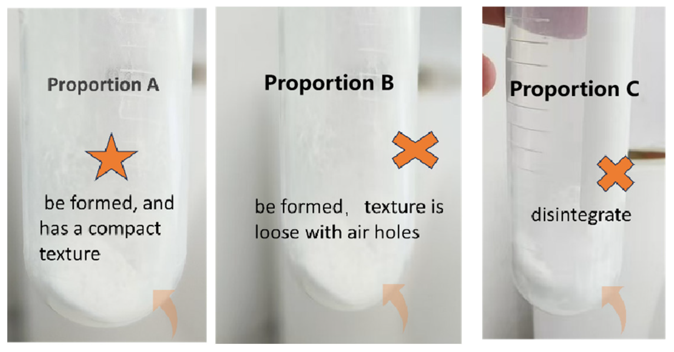
2.1. Optimization of the Binder Amount

The molar ratio of the silica binder to TPAOH was fixed at 10:1. The amount of silica added was set to 18%, 24%, and 30% of the mass of the starting zeolite as listed in Table 1. When the addition silica was 30%, the viscosity of the mixture was high, and the matrix was broken after drying. Conversely, when the addition amount was 24%, the matrix was found to be loose and low in strength after drying. Conversely, the sample with an addition of 18% silica exhibited a uniform, mechanically stable monolith as illustrated in Figure 1. Consequently, the optimal amount added was determined to be 18%.

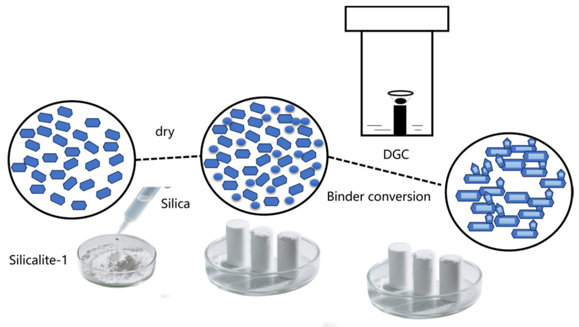
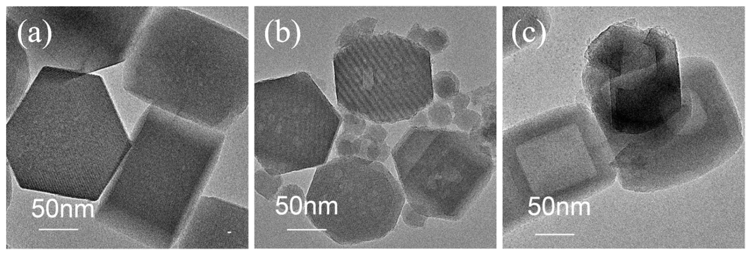
2.2. Characterization of Binder Conversion Process (Secondary Crystalization)

The binder was added to sil, and the mixture before binder conversion was denoted as sil-mix. Figure 2 shows the TEM images of sil, sil-mix and sil-s. The particle sizes of sil are all about 200 nm, showing typical hexagonal grains and clear lattice fringes (crystal plane spacing of 0.39 nm corresponding to the (101) crystal plane of the MFI structure, Figure 2a). In Figure 2b for sil-mix, amorphous silica particles attached to the surface of sil crystals can be observed. In Figure 2c for the monolithic sil-s, the disappearance of amorphous silica along with the newly formed crystals (about 50 nm) connected with the original crystals can be observed. The appearance of hollow structure implies that the starting sil was partially recrystallized during the secondary binder crystallization.
Figure 3 illustrates the XRD spectra of sil, sil-mix and sil-s. Sil shows typical MFI-type characteristic diffraction peaks at 2θ = 7.9°, 8.8°, and 23.1° (PDF#97-018-9000). All characteristic peaks are marked with an asterisk (*).The intensity of sil-s was 1.2 times that of the original sil. This result indicates that TPAOH induces amorphous SiO2 crystallization into MFI crystals during the secondary transformation. At the same time, sil also partially recrystallized and the crystallinity increased in line with the TEM results.

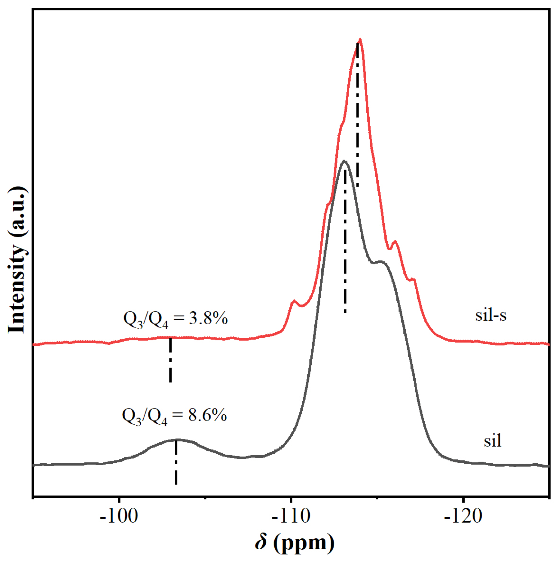
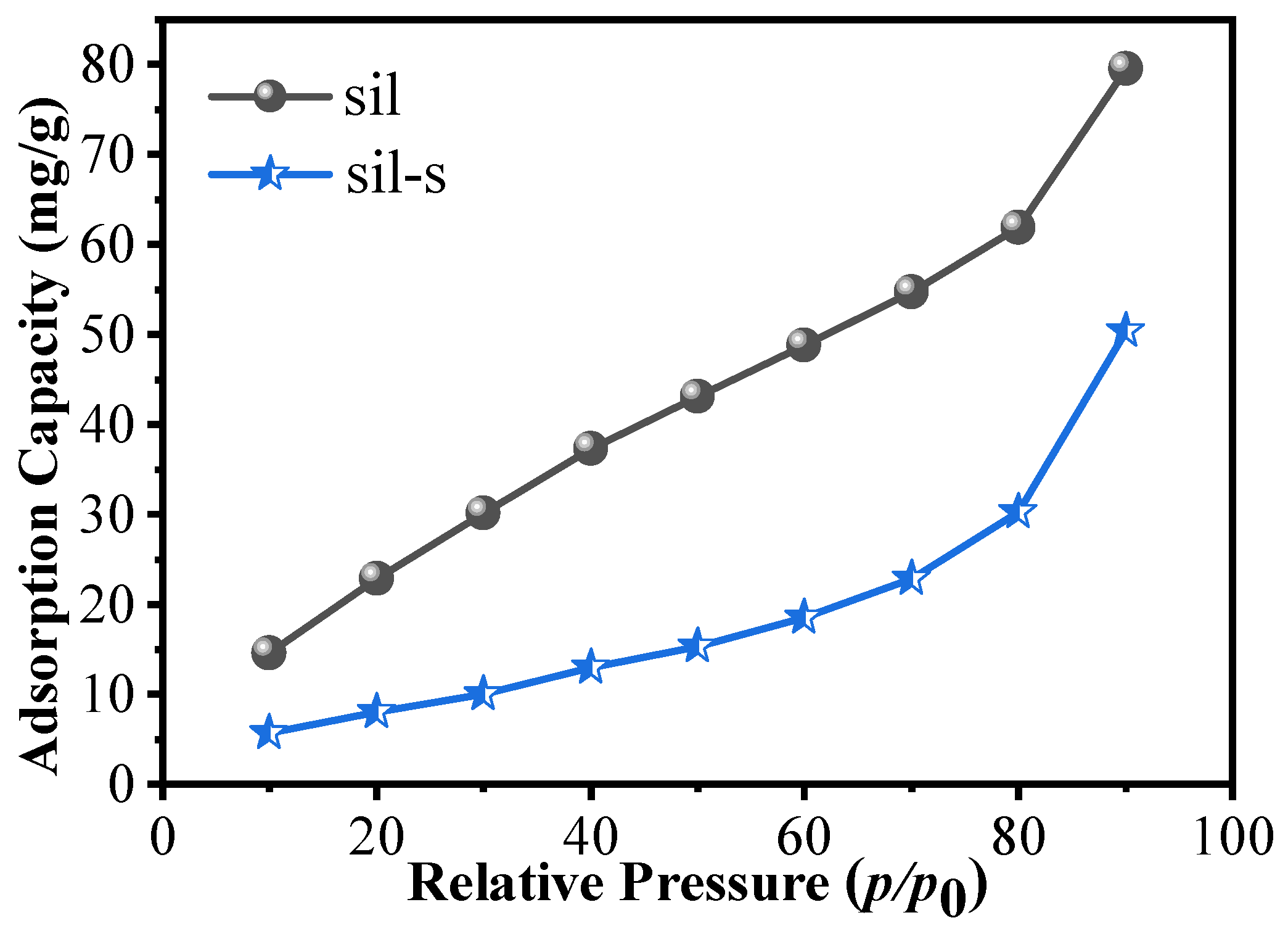
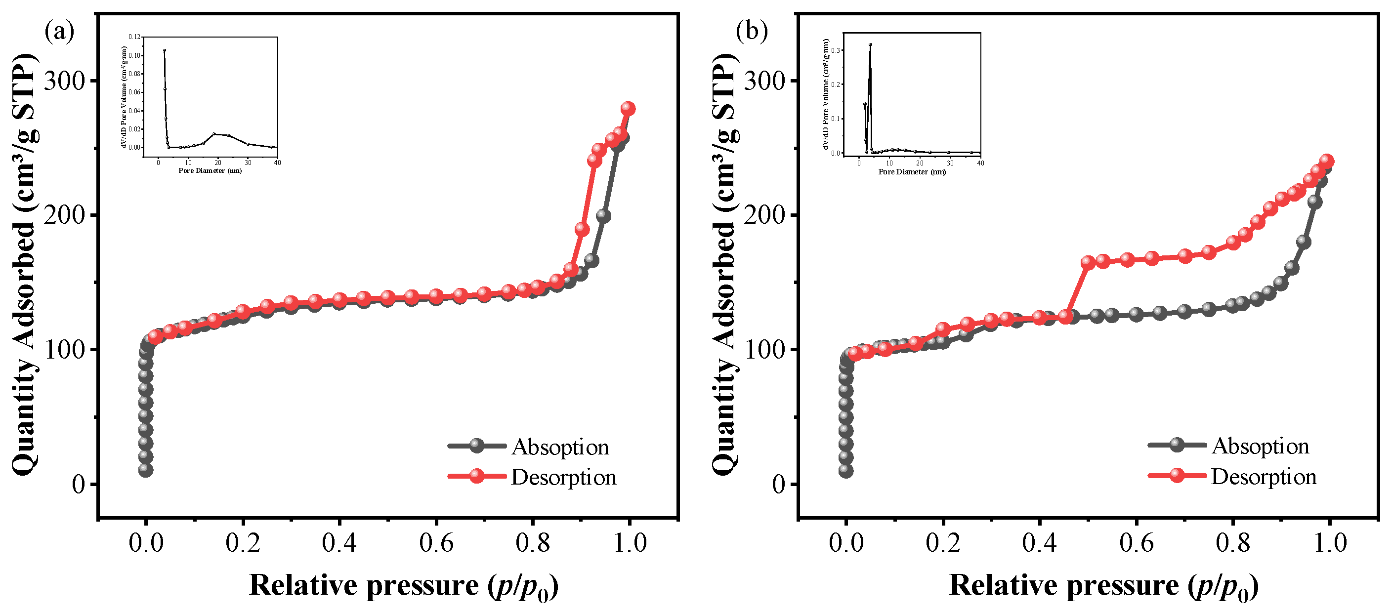
2.3. Comparison of Sil and Sil-s with Regard to Defects and Hydrophobicity

The silanol groups were resolved in FTIR spectra (Figure 4). The peak intensities of the hydroxyl nest (3555 cm−1) remained almost constant, but the peak intensities of the internal hydroxyl groups of sil-s (3726 cm−1, 3680 cm−1) were lower than those of sil. This indicates that during the secondary crystallization, the crystallization of binder silica to silicalite-1 and the starting sil also underwent partial recrystallization to repair some internal defects.
The changes in the concentration of silinol defects were quantitatively revealed by 29Si MAS-NMR spectroscopy (Figure 5). The resonances at −103 ppm and −115 ppm correspond to the Q3 structure (HO-Si-(OSi)3 and the Q4 structure (Si-(OSi)4, complete tetra-coordinated silicon). Based on the integral areas, the defect concentration Q3/Q4 of sil-s was significantly reduced from 8.6% to 3.8%. This result is consistent with the trend of FTIR analysis (Figure 4), confirming the significant reduction in the silanol defect concentration.
As shown in Figure 6, comparing the water vapor adsorption isotherms of sil and sil-s, it can be clearly seen that the water vapor adsorption capacity of sil-s is weakened, i.e., hydrophobicity is enhanced. The equilibrium adsorption of sil-s was significantly reduced from 80 mg/g to 50 mg/g at a relative pressure (P/P0) of 0.90, indicating enhanced hydrophobicity. The reduction in the density of hydrophilic silanol defects in sil-s compared with sil can explain its enhancement in hydrophobicity.

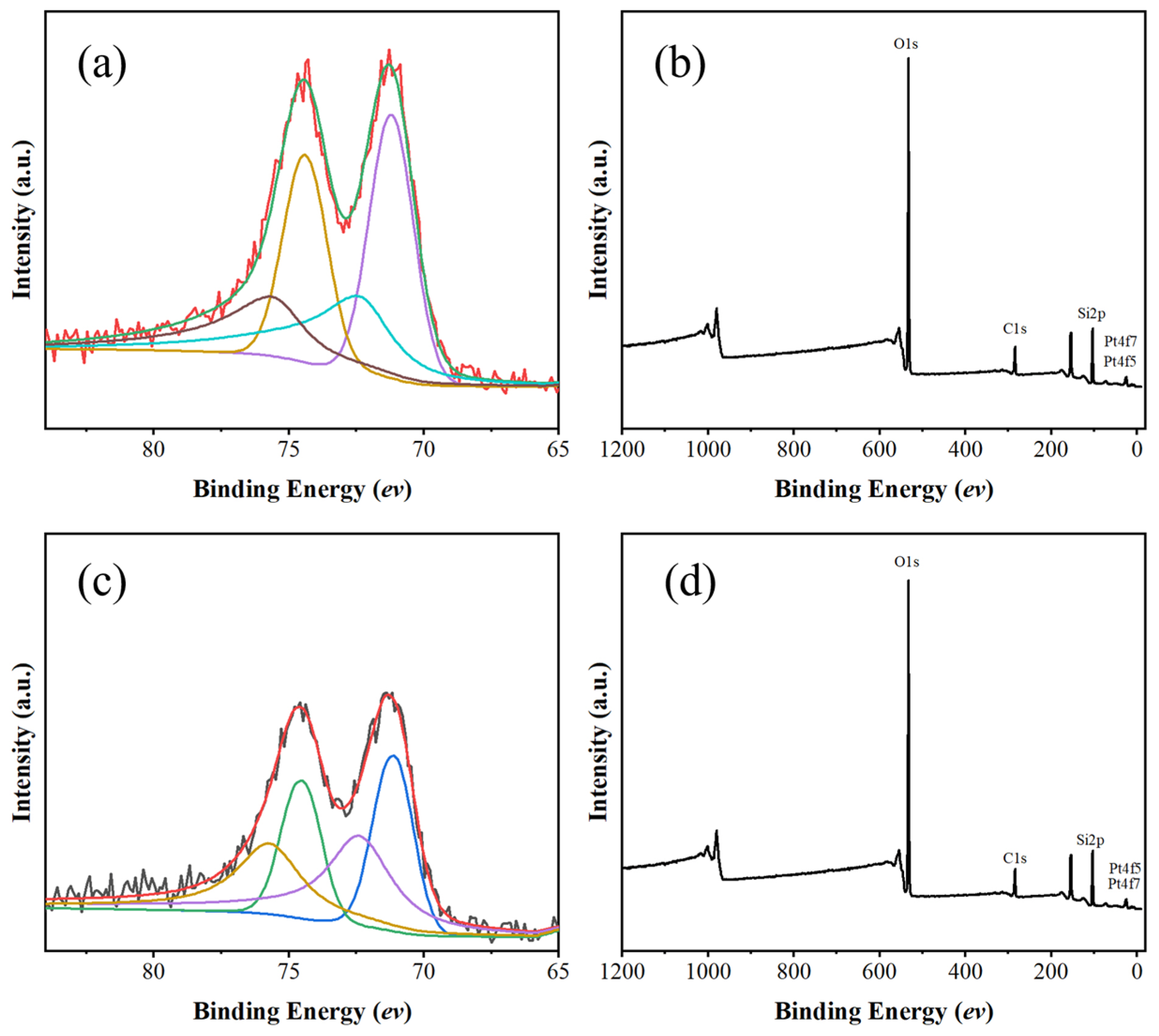
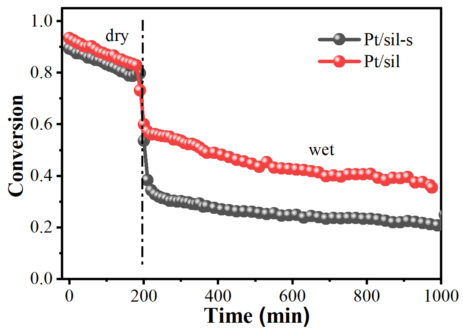
2.4. Pt/Sil and Pt/Sil-s Catalysts and Their Catalytic Performance in Hydrogen Oxidation Reaction

From Figure 7a, it can be observed that the hysteresis loops of Pt/sil samples are narrower, mainly appearing in the interval of 0.4–0.9 relative pressure, and the area of the loops is smaller. According to the IUPAC classification, this hysteresis loop mainly exhibits H3-type features, which are usually associated with slit-like pores formed by the accumulation of nanoparticles. The hysteresis loop of the Pt/sil-s sample is significantly wider than that of the Pt/sil, and a more pronounced loop is formed in the relative pressure interval of 0.4–1.0, with a significantly larger loop area. This type of hysteresis loop shows typical H2 characteristics, which is usually associated with “ink bottle” type of pore, i.e., irregular pore structure with wider pore body but narrower pore opening. The specific pore structure data for Pt/sil and Pt/sil-s are shown in Table 2.
The surface elemental states of Pt/sil and Pt/sil-s catalysts were analyzed by XPS spectroscopy as shown in Figure 8. It can be seen that Pt appears as dominated metallic Pt at 71.2 eV.
Figure 9 shows the TEM photographs of Pt/sil and Pt/sil-s and the corresponding Pt particle size distributions. The average Pt particle size of both is around 3 nm. Table 3 shows the CO chemisorption data for both Pt/sil and Pt/sil-s catalysts, and the Pt dispersion of both catalysts are close to each other, which is consistent with the TEM results.
Because tritium is an isotope of hydrogen, their chemical properties are similar. The hydrogen oxidation was used to simulate the tritium oxidation reaction (Figure 10).
Both Pt/sil and Pt/sil-s catalysts showed a decrease in activity without the introduction of saturated water vapor, which was due to the adsorption of product water on the catalysts. After 200 min, saturated water vapor was introduced, and both catalysts entered a relatively stable phase after a sudden drop. This drop may be due to the competitive adsorption of water vapor. Then, the conversion of both catalysts reached a relatively stable level with a slow decline. The conversion of Pt/sil decreased at a rate of 0.025%/min, but Pt/sil-s declined at a rate of 0.0125%/min, which was twice as stable as that of Pt/sil. It shows that Pt/sil-s formed by the better hydrophobic sil-s support is indeed more stable under wet conditions than Pt/sil.

3. Materials and Methods

3.1. Synthesis of Silicalite-1

The preparation of silicalite-1 zeolite involved the use of tetrapropylammonium hydroxide (TPAOH, 40 wt%, Beijing Huaiwei Ruike Chemical Co., Beijing, China) as the structure-directing agent and ethyl orthosilicate (TEOS, Aladdin, Shanghai, China) as the silicon source. These reagents were mixed according to the ratio (TPAOH/SiO2/H2O = 0.4/1/35). Aqueous TPAOH (52.74 g), TEOS (33.75 g), and ultrapure water (62.55 g) were added sequentially into a polytetrafluoroethylene-lined hydrothermal reactor. The mixture was then magnetically stirred for 12 h at room temperature to complete hydrolysis of TEOS. Subsequently, the mixture was heated to 80 °C and maintained for 3 h to remove ethanol as a hydrolysis by-product. The mixture was then supplemented with an equal mass of ultrapure water. The homogenized solution was subsequently subjected to hydrothermal crystallization at 175 °C for 72 h. The resulting product was washed with water, dried, and calcined at 550 °C for 5 h in synthetic air (21% O2/79% N2) to obtain silicalite-1 powder, herein referred to as sil.

3.2. Synthesis of Silicalite-1 Monolith

For the formation of sil-s monolith, sil powder (1.6 g), silica sol (0.72 g, 18% of sil) as a binder, and tetrapropylammonium hydroxide solution (TPAOH, 40 wt%, 0.244 g) were manually stirred thoroughly in a centrifuge tube using a Teflon rod for 30 min. The paste was dried at 80 °C for 2 h to form a monolith. Subsequently, the monolith was placed into a PTFE cup placed into a PTFE-lined reactor. Then, 3 mL of water was added into the bottle of the reactor and hydrothermally crystallized at 175 °C for 24 h. This step was to make the silica binder crystallize to MFI-type crystals (silicalite-1) under the guidance of TPAOH. The final product was subjected to drying and calcination. A binder-free silicalite-1 monolith was obtained and designated as sil-s. The sil-s monolith was ground into powders for characterization and loading of platinum.

3.3. Preparation of Platinum Catalysts with Sil and Sil-s as the Supports

The preparation of the Pt/sil catalyst involved gradual addition of 175 μL of an aqueous chloroplatinic acid solution (1g/12.5 mL, 2 wt% of loading) into 0.5 g of sil powder followed by mixing and grinding to yield a homogeneous yellow powder. The powder was dried at 110 °C for 3 h and calcined at 400 °C for 2 h in synthetic air. Then, it was reduced at 350 °C for 1 h in 10% H2/Ar to obtain gray Pt/sil catalyst.
Pt/sil-s catalysts were prepared in the same way as Pt/sil, only replacing sil with sil-s.

3.4. Characterization

The samples were analyzed by X-ray diffraction (XRD) using a HAOYUAN DX-2700BH X-ray diffractometer (Shenyang, China). The CuKα was used as the radiation source, the tube voltage was set at 40 kV and the tube current at 30 mA, and the scanning mode was selected as step scanning with 0.025°/step and a scanning range of 2θ = 5°–70°. In this paper, the peak intensity of diffraction per unit mass of the sample was used to characterize the crystallinity of the sample.
The electron microscope images of the samples were obtained using a JEM-2800 transmission electron microscope (TEM) from Japan Electronics (Tokyo, Japan). The accelerating voltage was 100 keV, under which the samples would not be damaged within a short duration. The sample was dispersed in ethanol and ultrasonicated for 20 min, and then 1–2 drops of the dispersed solution were dropped on a copper mesh with an ultrathin carbon film as the supporting film. The average particle size of the samples was obtained by counting more than 150 particles to ensure the reliability of the particle size data.
The 29Si dipolar decoupling magic angle nuclear magnetic resonance (MAS-NMR) spectra were acquired on a Bruker AVANCE III HD 600 MHz wide-cavity solid-state NMR spectrometer equipped with a 4 mm sample tube (Billerica, MA, USA). The resonance frequency of the Si was set to 119 MHz, the rotor speed to 8 kHz, the pulse width to 4.2 μs, the relaxation time to 20 s, and the number of scans to 562.
The infrared (IR) spectra were acquired on a Frontier type infrared spectrometer. The resolution was set to 4 cm−1 and the number of scanning was 8. The water vapor adsorption capacity was acquired using a gravimetric vapor adsorption tester (BSD-DVS) from Beijing Beishide. Before the adsorption, the samples were purged with 400 sccm of N2 at 250 °C for 360 min to remove the adsorbed water on the surface, and then the water vapor adsorption amounts at different partial pressures were measured at 25 °C. The amount of water vapor adsorbed on the samples can indicate the hydrophobicity of the samples.

4. Conclusions

Binder-free silicalite-1 monolith was successfully constructed from silicalite-1 powders using a binder conversion method. The optimal amount of silica binder was found to be 18% of the starting silicalite-1. In the process of secondary transformation, the binder silica crystallizes into silicalite-1, while the starting silicalite-1 also undergoes partial recrystallization. As a result, the concentration of silanol defects in the monolithic silicalite-1 is reduced and the hydrophobicity is enhanced. The platinum catalyst with a monolithic silicalite-1 molecular sieve as the support shows better stability in the hydrogen oxidation reaction with the conversion decline rate of 0.0125%/min.

Author Contributions

Conceptualization, supervision, C.X.; validation, T.W.; investigation, B.Y.; data curation, B.Y.; writing—original draft preparation, B.Y.; writing—review and editing, C.X. All authors have read and agreed to the published version of the manuscript.

Funding

The authors acknowledge the funding provided by INPC (YC0601).

Data Availability Statement

All data can be provided upon request.

Conflicts of Interest

The authors declare no conflicts of interest.

References

  1. Fiore, K. Nuclear Energy and Sustainability: Understanding ITER. Energy Policy 2006, 34, 3334–3341. [Google Scholar] [CrossRef]
  2. Rizzello, C.; Borgognoni, F.; Pinna, T.; Tosti, S. Review of Tritium Confinement and Atmosphere Detritiation System in Hot Cells Complex. Fusion Eng. Des. 2010, 85, 58–63. [Google Scholar] [CrossRef]
  3. Beloglazov, S.; Camp, P.; Hayashi, T.; Lepetit, L.; Perevezentsev, A.; Yamanishi, Y. Configuration and Operation of Detritiation Systems for ITER Tokamak Complex. Fusion Eng. Des. 2010, 85, 1670–1674. [Google Scholar] [CrossRef]
  4. Iwai, Y.; Sato, K.; Taniuchi, J.; Noguchi, H.; Kubo, H.; Harada, N.; Oshima, Y.; Yamanishi, T. Room-Temperature Reactor Packed with Hydrophobic Catalysts for the Oxidation of Hydrogen Isotopes Released in a Nuclear Facility. J. Nucl. Sci. Technol. 2011, 48, 1184–1192. [Google Scholar] [CrossRef]
  5. Xiao, C.; Yang, Y.; Zhou, X.; Du, Y.; Tan, Z. Humidity-Tolerant H2-O2 Recombination Platinum Catalyst for Mitigating Hydrogen Using Silicalite-1 as Support. Microporous Mesoporous Mater. 2019, 279, 395–399. [Google Scholar] [CrossRef]
  6. Iwai, Y.; Sato, K.; Yamanishi, T. Development of Pt/ASDBC Catalyst Applicable for Hydrogen Oxidation in the Presence of Saturated Water Vapor at Room Temperature. J. Plasma Fusion Res. 2010, 9, 332–337. [Google Scholar]
  7. Iwai, Y.; Sato, K.; Yamanishi, T. Development of Pt/ASDBC Catalyst for Room Temperature Recombiner of Atmosphere Detritiation System. Fusion Eng. Des. 2011, 86, 2164–2167. [Google Scholar] [CrossRef]
  8. Lakiss, L.; Gilson, J.-P.; Valtchev, V.; Mintova, S.; Vicente, A.; Vimont, A.; Bedard, R.; Abdo, S.; Bricker, J. Zeolites in a Good Shape: Catalyst Forming by Extrusion Modifies Their Performances. Microporous Mesoporous Mater. 2020, 299, 110114. [Google Scholar] [CrossRef]
Scheme 1. The formulation of binder-free silicalite-1 monolith through a binder-conversion route.
Catalysts 15 00584 sch001
Figure 1. Photos of samples after shaping with different material ratios.
Catalysts 15 00584 g001
Figure 2. TEM images of sil (a), sil-mix (b) and sil-s (c).
Catalysts 15 00584 g002
Figure 3. XRD patterns of sil, sil-mix and sil-s.
Catalysts 15 00584 g003
Figure 4. Fourier-transform infrared (FTIR) spectra of sil and sil-s.
Catalysts 15 00584 g004
Figure 5. 29Si MAS-NMR spectra of sil and sil-s.
Catalysts 15 00584 g005
Figure 6. Water vapor adsorption isotherms for sil and sil-s.
Catalysts 15 00584 g006
Figure 7. N2 adsorption and desorption images of Pt/sil (a), Pt/sil-s (b) and their pore size distribution.
Catalysts 15 00584 g007
Figure 8. (a) High-resolution Pt 4f XPS spectrum of Pt/sil; (b) XPS survey of Pt/sil; (c) high-resolution XPS Pt 4f spectrum of Pt/sil-s; (d) XPS survey of Pt/sil-s.
Catalysts 15 00584 g008
Figure 9. Comparative TEM analysis: (a,c) TEM images of Pt/SiL and Pt/SiL-S; (b,d) corresponding Pt nanoparticle size distributions.
Catalysts 15 00584 g009
Figure 10. Hydrogen oxidation activity for Pt/sil-s and Pt/sil in the dry and wet conditions (saturated with water vapor) at 25 °C, with a reaction gas mixture of 0.1% H2 and 20% O2 balanced with Ar.
Catalysts 15 00584 g010
Table 1. Material ratio of silicalite-1 shaping.
Proportions (Sil/SiO2)Sil/gSilica Sol/gTPAOH/g (nTPAOH/nSiO2 = 0.1)
A (18%)1.60.720.244
B (24%)1.60.960.325
C (30%)1.61.200.407
Table 2. Specific surface area of Pt/sil-s vs. Pt/sil catalysts and pore volume, microporous pore volume and mesoporous pore volume.
SampleSBET
(m2/g)
Vt
(cm3/g)
Vmic
(cm3/g)
Vmeso
(cm3/g)
ravg
(nm)
Pt/sil465.680.3140.1160.2727.63
Pt/sil-s416.930.2850.1150.3204.72
Table 3. Pt/sil vs. Pt/sil-s catalyst dispersion.
Cat.Percent of PtMetal Dispersion
(%)
Cube Crystallite Size
(nm)
Pt/sil2 wt%7.1613.19
Pt/sil-s2 wt%7.4312.71
Disclaimer/Publisher’s Note: The statements, opinions and data contained in all publications are solely those of the individual author(s) and contributor(s) and not of MDPI and/or the editor(s). MDPI and/or the editor(s) disclaim responsibility for any injury to people or property resulting from any ideas, methods, instructions or products referred to in the content.

