
Sustainable Hydrogen from Methanol: NiCuCe Catalyst Design with CO2-Driven Regeneration for Carbon-Neutral Energy Systems


Abstract

1. Introduction
2. Results and Discussion
2.1. Catalyst Reaction Mechanism
2.2. Catalyst Active Center
- (1)
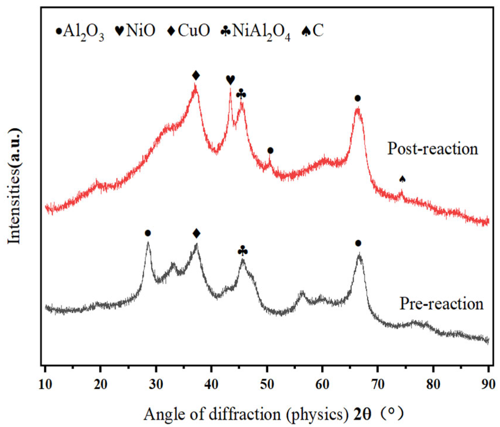
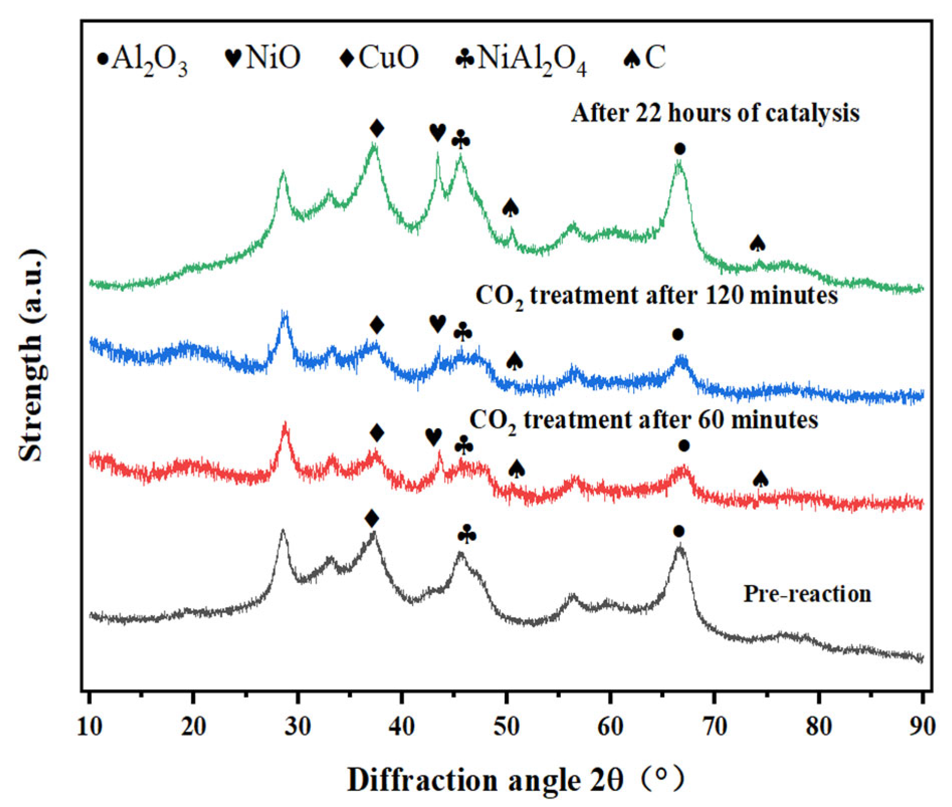
- Methanol cracking products (H2 and CO) exhibit strong reducing properties. Fresh catalysts predominantly contain CuO (Cu2+). Figure 1 shows enhanced CuO crystallinity with the reaction time, which coincides with catalytic deactivation, suggesting a progressive reduction of Cu+/Cu2+ to Cu0.
- (2)
- If Cu0 were the active species, then catalytic performance should stabilize or improve with Cu0 accumulation. However, Figure 3 demonstrates a gradual activity loss, which contradicts this hypothesis.
- (3)
- Choi et al. [19] report increased Cu2+ content during methanol reforming, correlating with enhanced H2 selectivity, thereby supporting Cu2+ as the active species.
- (4)
- Figure 1 reveals intensified NiO (Ni2+) diffraction peaks post-reaction, despite the marginal performance decline. This indicates that Ni2+ → Ni0 reduction dominates over time. Furthermore, Kwon et al. [20] demonstrate that NiAl2O4 spinel enhances dispersion of active Ni species in Ni/Al2O3 systems. Ni2+ ions liberated from NiAl2O4 form smaller metallic Ni particles (<5 nm) while strengthening metal–support interactions, thereby improving the activity, selectivity, stability, and coking resistance.
2.3. Response Pathways
2.4. Regeneration of Ni-Based Catalysts
3. Experimental Details
- Ctotal—Total C content in the product;
- CMeOH—Content of CH3OH in the product;
- CCH4—Content of CH4 in the product;
- CCO—Content of CO in the product;
- CCO2—Content of CO2 in the product;
- CMF—Content of MF in the product;
- CDME—Content of DMF in the product;
- HH2—Content of H2 in the product;
- XMeOH—Cleavage rate of CH3OH;
- SCO—The selectivity of CO;
- SH2—The selectivity of H2;
- MMeOH—Molar mass of CH3OH.
4. Conclusions
Author Contributions
Funding
Data Availability Statement
Conflicts of Interest
Abbreviations
| XPS | X-ray Photoelectron Spectroscopy |
| XRD | X-ray diffraction |
| TPD | Temperature programmed desorption |
| TPR | Temperature Program Restore |
| TPO | Temperature program oxidation |
| SEM | Scanning electron microscope |
| BET | Brunner−Emmet−Teller measurements |
References
- Verhelst, S.; Turner, J.W.; Sileghem, L.; Vancoillie, J. Methanol as a Fuel for Internal Combustion Engines. Prog. Energy Combust. Sci. 2019, 70, 43–88. [Google Scholar] [CrossRef]
- Zhen, X.; Wang, Y. An Overview of Methanol as an Internal Combustion Engine Fuel. Renew. Sustain. Energy Rev. 2015, 52, 477–493. [Google Scholar] [CrossRef]
- Ludwig, R. The Structure of Liquid Methanol. ChemPhysChem 2005, 6, 1369–1375. [Google Scholar] [CrossRef]
- Shamsul, N.S.; Kamarudin, S.K.; Rahman, N.A.; Kofli, N.T. An Overview on the Production of Bio-Methanol as Potential Renewable Energy. Renew. Sustain. Energy Rev. 2014, 33, 578–588. [Google Scholar] [CrossRef]
- Tabibian, S.S.; Sharifzadeh, M. Statistical and Analytical Investigation of Methanol Applications, Production Technologies, Value-Chain and Economy with a Special Focus on Renewable Methanol. Renew. Sustain. Energy Rev. 2023, 179, 113281. [Google Scholar] [CrossRef]
- Parris, D.; Spinthiropoulos, K.; Ragazou, K.; Giovou, A.; Tsanaktsidis, C. Methanol, a Plugin Marine Fuel for Green House Gas Reduction—A Review. Energies 2024, 17, 605. [Google Scholar] [CrossRef]
- Liu, M.; Li, C.; Koh, E.K.; Ang, Z.; Lee Lam, J.S. Is Methanol a Future Marine Fuel for Shipping? J. Phys. Conf. Ser. 2019, 1357, 012014. [Google Scholar] [CrossRef]
- Bepari, S.; Kuila, D. Steam Reforming of Methanol, Ethanol and Glycerol over Nickel-Based Catalysts—A Review. Int. J. Hydrogen Energy 2020, 45, 18090–18113. [Google Scholar] [CrossRef]
- Coronado, I.; Stekrova, M.; García Moreno, L.; Reinikainen, M.; Simell, P.; Karinen, R.; Lehtonen, J. Aqueous-Phase Reforming of Methanol over Nickel-Based Catalysts for Hydrogen Production. Biomass Bioenergy 2017, 106, 29–37. [Google Scholar] [CrossRef]
- Hu, B.; Shu, R.; Khairun, H.S.; Tian, Z.; Wang, C.; Kumar Gupta, N. Methanol Steam Reforming for Hydrogen Production over Ni-Based Catalysts: State-Of-The-Art Review and Future Prospects. Chem. Asian J. 2024, 19, e202400217. [Google Scholar] [CrossRef]
- Moura-Nickel, C.D.; Ortiz Florenciano, J.T.; Scaratti, G.; Moreira, R.D.F.P.M.; José, H.J. Regeneration Process Using CO2 in Situ of Ni-Y2O3-Al2O3 Aerogel Spent Catalysts from Dry Reforming with Continuous Syngas Production. Chem. Eng. Sci. 2021, 231, 116319. [Google Scholar] [CrossRef]
- Mahlaba, S.V.L.; Valand, J.; Mahomed, A.S.; Friedrich, H.B. A Study on the Deactivation and Reactivation of a Ni/Al2O3 Aldehyde Hydrogenation Catalyst: Effects of Regeneration on the Activity and Properties of the Catalyst. Appl. Catal. B Environ. 2018, 224, 295–304. [Google Scholar] [CrossRef]
- Yusuf, M.; Farooqi, A.S.; Keong, L.K.; Hellgardt, K.; Abdullah, B. Contemporary Trends in Composite Ni-Based Catalysts for CO2 Reforming of Methane. Chem. Eng. Sci. 2021, 229, 116072. [Google Scholar] [CrossRef]
- Wang, J.; Shi, F.; Liu, C.; Lu, Y.; Lin, X.; Hou, D.; Li, J.; Wang, D.; Zheng, Z.; Zheng, Y. Efficient and Stable Ni-Supported Novel Porous Ca-Mg-Al Complex Oxide Catalyst for Catalytic Pyrolysis of Oleic Acid into Gasoline-Kerosene Rich Production Using Methanol as a Hydrogen Donor: Synthesis Methods and Process Optimization. Fuel Process. Technol. 2023, 241, 107623. [Google Scholar] [CrossRef]
- Fracchia, M.; Roongcharoen, T.; Coduri, M.; Sementa, L.; Saeedi, S.; Nguyen, X.T.; Stoian, D.C.; Pitzalis, E.; Campanella, B.; Evangelisti, C.; et al. Enhancing and Understanding the Stability of Ni Catalysts via In-Promotion for the Steam Reforming of Oxygenates: An in-Depth Operando XRD-XAS and Modeling Investigation. Appl. Catal. B Environ. Energy 2025, 366, 125074. [Google Scholar] [CrossRef]
- Zhang, J.; Yang, F.; Fang, T.; Wang, B.; Yang, Q.; Wu, Z.; Zhang, Z. Composite Strategy for Enhancing Dehydrogenation Performance of Pd/CeO2 Catalysts in Dodecahydro-N-Ethylcarbazole through Support and Active Metal Optimization. Int. J. Hydrogen Energy 2025, 120, 78–88. [Google Scholar] [CrossRef]
- Zengel, D.; Marchuk, V.; Kurt, M.; Maurer, F.; Salcedo, A.; Michel, C.; Loffreda, D.; Aouine, M.; Loridant, S.; Vernoux, P.; et al. Pd Loading Threshold for an Efficient Noble Metal Use in Pd/CeO2 Methane Oxidation Catalysts. Appl. Catal. B Environ. Energy 2024, 358, 124363. [Google Scholar] [CrossRef]
- Zhang, C.; Wang, C.; Shi, Q.; Wang, X.; Zhao, S.; Liang, L.; Wang, Q.; Wang, L.; Cheng, Y. Constructing Ni/CeO2 Synergistic Catalysts into LiAlH4 and AlH3 Composite for Enhanced Hydrogen Released Properties. Appl. Catal. B Environ. Energy 2024, 359, 124521. [Google Scholar] [CrossRef]
- Choi, Y.; Stenger, H.G. Fuel Cell Grade Hydrogen from Methanol on a Commercial Cu/ZnO/Al2O3 Catalyst. Appl. Catal. B Environ. 2002, 38, 259–269. [Google Scholar] [CrossRef]
- Kwon, Y.; Eichler, J.E.; Mullins, C.B. NiAl2O4 as a Beneficial Precursor for Ni/Al2O3 Catalysts for the Dry Reforming of Methane. J. CO2 Util. 2022, 63, 102112. [Google Scholar] [CrossRef]
- Goma, D.; Delgado, J.J.; Lefferts, L.; Faria, J.; Calvino, J.J.; Cauqui, M.Á. Catalytic Performance of Ni/CeO2/X-ZrO2 (X = Ca, Y) Catalysts in the Aqueous-Phase Reforming of Methanol. Nanomaterials 2019, 9, 1582. [Google Scholar] [CrossRef] [PubMed]
- Farooq, M.S.; Baig, A.; Wei, Y.; Liu, H.; Zeng, Z.; Shi, Z. A Comprehensive Analysis of a Compact-Sized Methanol Cracking Unit for Hydrogen Production. Int. J. Hydrogen Energy 2024, 87, 822–837. [Google Scholar] [CrossRef]
- Zhang, B.; Jiang, Y.; Lu, Y.; Chen, Y.; Chen, L.; Yang, Z. Effect of Carriers on the Characteristics of CuNiCe Catalyst for Methanol Decomposition in Engine Applications. Int. J. Hydrogen Energy 2025, 118, 68–79. [Google Scholar] [CrossRef]
- Djinović, P.; Črnivec, I.G.O.; Erjavec, B.; Pintar, A. Details Behind the Self-Regeneration of Supported NiCo/Ce0.8 Zr0.2 O2 Bimetallic Catalyst in the CH4 –CO2 Reforming Reaction. ChemCatChem 2014, 6, 1652–1663. [Google Scholar] [CrossRef]
- Düdder, H.; Kähler, K.; Krause, B.; Mette, K.; Kühl, S.; Behrens, M.; Scherer, V.; Muhler, M. The Role of Carbonaceous Deposits in the Activity and Stability of Ni-Based Catalysts Applied in the Dry Reforming of Methane. Catal. Sci. Technol. 2014, 4, 3317–3328. [Google Scholar] [CrossRef]
- Bulutoglu, P.S.; Say, Z.; Bac, S.; Ozensoy, E.; Avci, A.K. Dry Reforming of Glycerol over Rh-Based Ceria and Zirconia Catalysts: New Insights on Catalyst Activity and Stability. Appl. Catal. A Gen. 2018, 564, 157–171. [Google Scholar] [CrossRef]


| Type | SSA (m2/g) | Vp (m3/g) | Dp (nm) |
|---|---|---|---|
| Post-reaction | 127.95 | 0.16 | 5.93 |
| Pre-reaction | 149.04 | 0.21 | 6.77 |
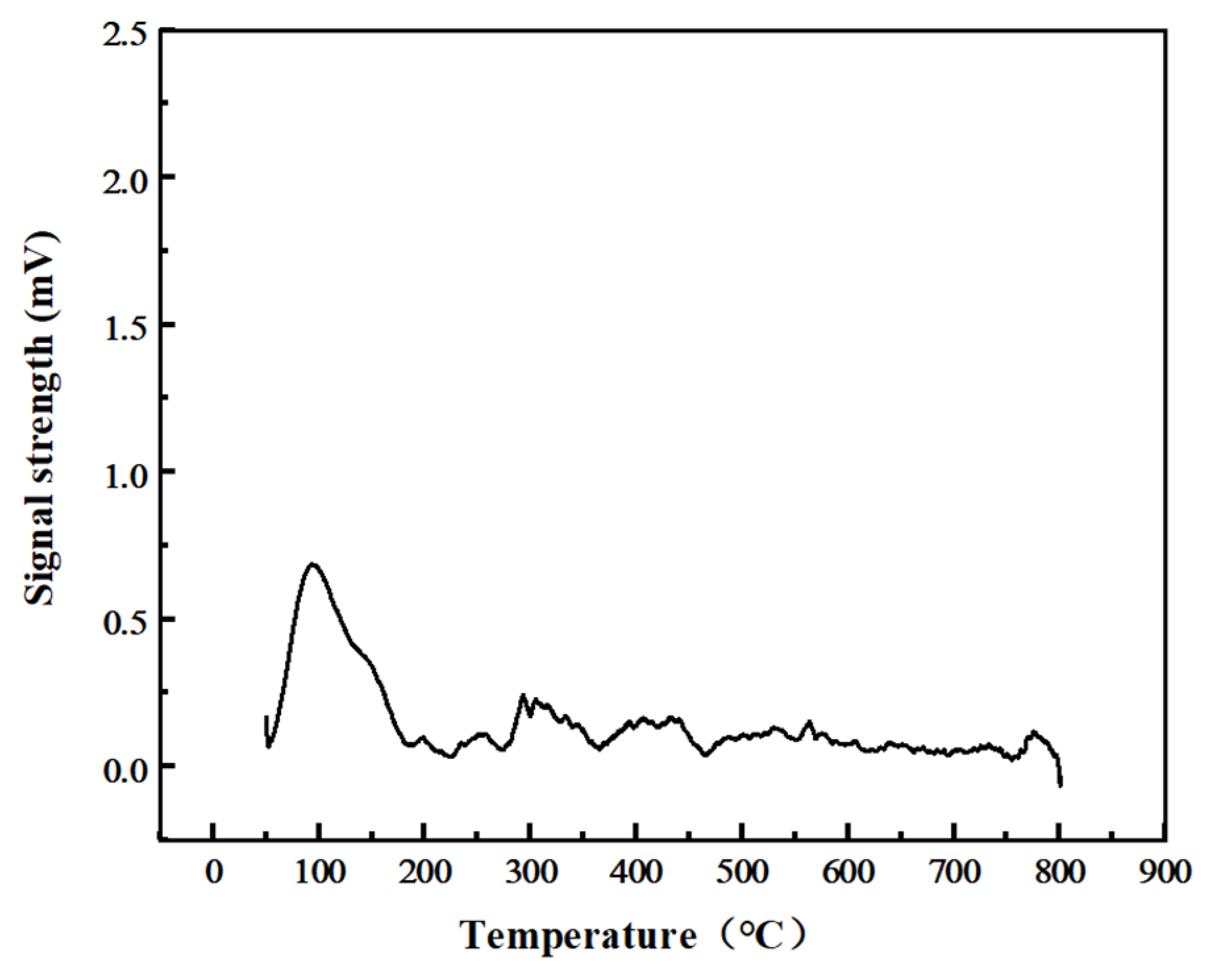
| Test Items | Peak Temperature(°C) | Peak Area | Oxygen Consumption (mmol/g) |
|---|---|---|---|
| TPO | 208 °C | 331 | 1.7212 |
| TPO after TPD-CO2 | 93 °C | 108 | 0.5616 |
| Test Items | Peak Temperature (°C) | Peak Area | CO2 Consumption (mmol/g) |
|---|---|---|---|
| TPD-CO2 | 120 °C/310 °C | 4255 | 1.2996 |
| TPD-CO2 after 60 min CO2 gasification | 236 °C | 2676 | 0.8173 |
| TPD-CO2 after 120 min CO2 gasification | 229 °C | 1637 | 0.5266 |
Disclaimer/Publisher’s Note: The statements, opinions and data contained in all publications are solely those of the individual author(s) and contributor(s) and not of MDPI and/or the editor(s). MDPI and/or the editor(s) disclaim responsibility for any injury to people or property resulting from any ideas, methods, instructions or products referred to in the content. |
© 2025 by the authors. Licensee MDPI, Basel, Switzerland. This article is an open access article distributed under the terms and conditions of the Creative Commons Attribution (CC BY) license (https://creativecommons.org/licenses/by/4.0/).
Share and Cite
Jiang, Y.; Zhao, L.; Li, S. Sustainable Hydrogen from Methanol: NiCuCe Catalyst Design with CO2-Driven Regeneration for Carbon-Neutral Energy Systems. Catalysts 2025, 15, 478. https://doi.org/10.3390/catal15050478
Jiang Y, Zhao L, Li S. Sustainable Hydrogen from Methanol: NiCuCe Catalyst Design with CO2-Driven Regeneration for Carbon-Neutral Energy Systems. Catalysts. 2025; 15(5):478. https://doi.org/10.3390/catal15050478
Chicago/Turabian StyleJiang, Yankun, Liangdong Zhao, and Siqi Li. 2025. "Sustainable Hydrogen from Methanol: NiCuCe Catalyst Design with CO2-Driven Regeneration for Carbon-Neutral Energy Systems" Catalysts 15, no. 5: 478. https://doi.org/10.3390/catal15050478
APA StyleJiang, Y., Zhao, L., & Li, S. (2025). Sustainable Hydrogen from Methanol: NiCuCe Catalyst Design with CO2-Driven Regeneration for Carbon-Neutral Energy Systems. Catalysts, 15(5), 478. https://doi.org/10.3390/catal15050478