Abstract
Under mild conditions, the effective conversion of carbon dioxide (CO2) into formic acid (HCOOH) and carbon monoxide (CO) represents a promising avenue for mitigating greenhouse gas emissions and addressing energy crises. In this work, we analyzed the electro-catalytic activities of six metals (Ti, Fe, Ni, Cu, Zn, and Cr) anchored on monolayer molybdenum telluride (TM@MoTe2) for the CO2 reduction reaction (CO2RR) from CO2 to HCOOH and CO. Compared to the reversible hydrogen electrode, the limiting potential for HCOOH production on Ni@MoTe2 is only about −0.38 V, and it is only about −0.20 V for the CO production on Cu@MoTe2. The limiting potential is concerned with the free energies of *OCHO and *COOH. Both the CO2RRs suppress the competing hydrogen evolution reaction (HER) and exhibit good selectivity for the desired reaction products. These features enable the efficient conversion of CO2 into HCOOH on Ni@MoTe2 or CO on Cu@MoTe2. Our calculations could provide valuable insights for the design and synthesis of high-performance catalysts based on MoTe2.
1. Introduction
In recent years, with the rapid global economic development, the extensive utilization of fossil fuels has given rise to two critical issues. Firstly, the excessive emission of carbon dioxide (CO2) gas disrupts the equilibrium of global carbon cycling, resulting in the greenhouse effect. Secondly, humanity is confronted with an impending energy crisis [1,2]. To address these challenges, conducting carbon dioxide reduction reactions (CO2RR) under mild environmental conditions has emerged as a promising approach. This process involves employing suitable catalysts to electrochemically reduce excess atmospheric CO2 to yield industrially valuable C1 (CH4, CH3OH, HCOOH, and CO), C2 (CH3CH3, C2H5OH, CH3COOH, and CH2CH2), and higher carbon products [3,4,5,6,7,8]. Importantly, CO2RR occurs under mild conditions and can harness clean energy sources such as solar and wind power; thereby, it will not aggravate the crisis of fossil fuels, and at the same time it will not cause secondary damage to the environment. Since the inception of CO2RR, substantial efforts have been made by predecessors in this domain. In recent years, a plethora of electro-catalysts encompassing metals, metal oxides, and carbon-based materials have been extensively explored, both experimentally and theoretically, to enhance CO2RR energy efficiency [9,10,11].
Single-atom catalysts (SACs) can be individually dispersed onto substrates, maximizing atomic utilization and mitigating the cost associated with noble metals. The attributes of SACs, including low metal loading, high catalytic activity, and exceptional selectivity, have rendered them a burgeoning realm within the field of electro-catalysis [12,13,14,15,16]. Moreover, transition metal di-chalcogenides (TMD) have been increasingly reported as electro-catalysts for CO2RR in recent years [17,18,19,20,21,22,23,24,25]. A single Co atom supported on monolayer MoS2 demonstrated exceptional CO2 activation and conversion capabilities [24]. Ru@1T’-MoS2 and Pt@1T’-MoS2 catalysts could efficiently reduce CO2 to CH4 and CH3OH at relatively low potentials (−0.56 V and −0.73 V, respectively), thereby presenting potential avenues for highly effective CO2 conversion [22]. In addition, the single Cu atom embedded in monolayer MoS2 also exhibited excellent performance in electro-catalytic CO2RR [20]. It also has been reported that Ni anchored on monolayer WTe2 may be a promising electro-catalytic material for efficient CO2 reduction to HCOOH [25]. MoTe2 is a representative material among transition metal tellurides [26]. Employing chemical vapor deposition, the sub-10-nm thick 2H-phase MoTe2 (2H-MoTe2) films can be synthesized in experiments [27]. Theoretically, 2H-MoTe2 is more stable than the distorted octahedral structure of the 1T’ phase [28]. 2H-MoTe2 has been utilized to investigate the reaction mechanisms of CO2RR and the competing HER. It was found that the edges of MoTe2 show promise as active and selective catalysts for alkaline CO2RR [29].
Bagger et al. classified metal electrode materials according to different catalytic reduction products (HCOOH, CO, H2, and hydrocarbons) [30]. We selected the third-period transition metal TM atoms (Ti, Fe, Ni, Cu, and Zn) mentioned in their study for discussion. Additionally, Cr from the same period has been demonstrated as a single-atom catalyst (SAC) with low limiting potential and good selectivity in the CO2RR process [31]. Therefore, we chose Ti, Cr, Fe, Ni, Cu, and Zn anchored on MoTe2 as SACs. Through structural stability analysis, free energy pathway calculations, and selectivity screening, Ni and Cu anchored on monolayer MoTe2 (Ni@MoTe2 and Cu@MoTe2) were identified as exhibiting remarkable properties, including low over-potentials (−0.38 V and −0.20 V vs. RHE) and high product selectivity. Finally, the activation mechanism of CO2 was explored.
2. Results and Discussion
2.1. Structure and Stability
Molybdenum ditelluride exhibits a crystalline configuration with a hexagonal lattice structure consisting of three atomic layers. Figure 1a shows the trigonal prismatic configuration of the 2H-MoTe2, which is relatively more stable [32]. The central layer is composed of molybdenum atoms, while the upper and lower layers consist of tellurium atoms, collectively forming a three-layer sandwich structure. Within the atomic layers, molybdenum atoms are robustly bound to six tellurium atoms through pronounced covalent bonds. The lattice constant is about 0.353 nm [33]. The anchoring of TM atoms directly above the Mo atom and connected to three Te atoms (referred to as the T1 site) is considered to be more stable [25]. Therefore, we considered the possibility of anchoring Ti, Cr, Fe, Ni, Cu, and Zn atoms at the T1 site in a 4 × 4 2H-MoTe2 supercell. The top view and side view of the anchored structure are shown in Figure 1b. The binding energy between the TM atoms and MoTe2 is shown in Figure 1c. The binding energies () of TM atoms on MoTe2 can be expressed according to following relation,
where , , and represent the total energies of TM@MoTe2, pure MoTe2, and the isolated TM atom, respectively. The negative binding energies show that Ti, Cr, Fe, Ni, and Cu atoms adsorbed on the MoTe2 substrate are stable and unlikely to desorb. In comparison, structural optimization reveals that the Zn atom cannot be adsorbed onto MoTe2. The optimized structures of TM@MoTe2 (TM = Ti, Cr, Fe, Ni, Cu, and Zn) can be found in Figure S1 (see Supporting Material). Since Zn@MoTe2 may be unstable, it will not be considered further. We calculated the Bader charges and atomic radii of TM atoms on TM@MoTe2 (Table S1 in Supporting Material). The results reveal that TM atoms with larger radii exhibit greater charge transfer, as larger atomic radii lead to less localized electrons. Moreover, TM atoms with larger radii generally possess lower electronegativity, making their electrons more susceptible to attraction by the more electronegative Mo atoms. However, no clear correlation was observed between the Bader charges/atomic radii of TM atoms on TM@MoTe2 and the binding energy values, suggesting the involvement of more complex interactions. Compared to other systems analyzed in this study, Ni@MoTe2 is a promising candidate for CO2RR with the lowest binding energy of Ni anchoring. We investigated the possibility of TM forming clusters on the substrate using Ni as an example. The transition state energy barriers for the formation of clusters with two, three, and four Ni atoms on the substrate are determined to be 1.69 eV, 1.45 eV, and 1.63 eV, respectively, as illustrated in Figure S2. Hence, we conclude that the diffusion and clustering of transition metal atoms on the substrate are hindered.
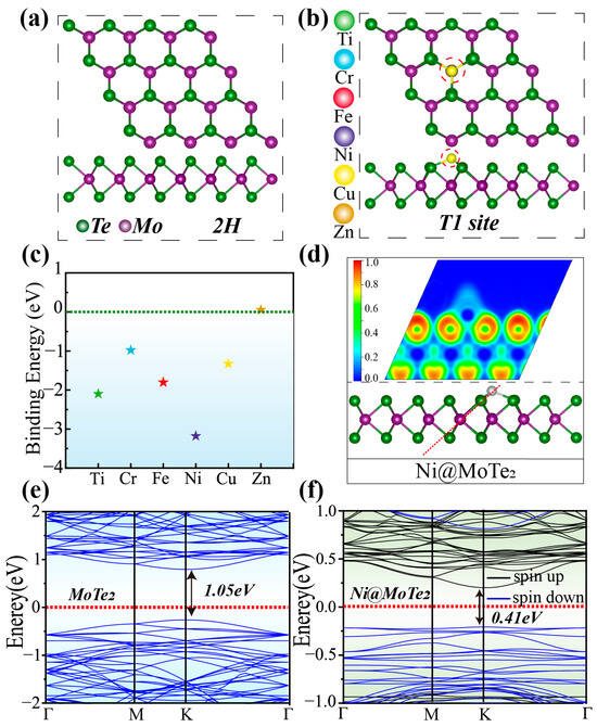
Figure 1.
(a) Top and side views of 2H-MoTe2. (b) Top and side views of TM atoms adsorbed at the T1 site. (c) Binding energy of Ti, Cr, Fe, Ni, Cu, and Zn atoms on MoTe2. (d) ELF of Ni@MoTe2 at the T1 site. The red dashed line indicates the selected plane. (e) Band structure of MoTe2. (f) Band structure of Ni@MoTe2.
Additionally, we calculated the electronic localization function (ELF) to analyze the bonding characteristics between the transition metal atoms and the substrate. The results for Ni@MoTe2 are shown in Figure 1d. Similar results for other TM@MoTe2 can be found in Figure S3 (see Supporting Material). We found that the ELF value around the Ni atom is relatively low, while it is higher around the adjacent Te atoms. The bonding region between Ni and Mo exhibits moderate ELF values, indicating partial electron sharing, consistent with the characteristics of an ionic-covalent bond. The other TM@MoTe2 structures (TM = Ti, Cr, Fe, and Cu) also exhibit similar phenomena. Combining the Bader charges and atomic radii of TM atoms in TM@MoTe2 (Table S1 in Supporting Material), we employed the conventional charge density method (ρ = Qbader/r3) to qualitatively characterize the magnitude of ELF values. The analysis reveals that the degree of electron localization around TM atoms follows the order Ti > Cr > Fe > Cu > Ni, which is consistent with the ELF mapping results. Furthermore, we computed the band structure of pristine MoTe2, as illustrated in Figure 1e, which shows a band gap width of 1.05 eV, consistent with previous reports [34]. After anchoring Ni on MoTe2, the band gap of Ni@MoTe2 decreases to be about 0.41 eV, as shown in Figure 1f, enhancing the metallic character of the substrate material, which is expected to facilitate electron transfer during the electrochemical reduction process. The band structures of other TM@MoTe2 structures are shown in Figure S4 (see Supporting Material). They also exhibit varying degrees of band gap reduction upon anchoring TM atoms. Therefore, TM@MoTe2 (TM = Ti, Cr, Fe, Ni, and Cu) demonstrates the potential to serve as an excellent catalyst [35,36,37,38,39].
According to the subsequent calculations, Ni@MoTe2 and Cu@MoTe2 are promising candidates for excellent catalysts. Therefore, AIMD simulations were performed on the selected materials with an expanded 2 × 2 × 1 supercell at 300 K for 9 ps to assess the thermal stability of the two structures. As shown in Figure S5 (see Supporting Material), both the temperature (red curve) and energy (purple curve) of the designed catalysts fluctuate around equilibrium. The images inserted in the figure represent the corresponding structures of the studied catalysts after the 9 ps AIMD simulation. Following the AIMD simulations, no significant deformation or fracture of the designed structures was observed. The temperature/energy fluctuations and geometric structures demonstrate good thermodynamic stability. This ensures the feasibility of Ni@MoTe2 and Cu@MoTe2 as the electro-catalysts of CO2RR in experimental studies.
2.2. Free Energy of CO2 Reduction to HCOOH and CO
For the five TM@MoTe2 (TM = Ti, Cr, Fe, Ni, and Cu) structures, the CO2 molecule can successfully adsorb on the metal atoms. The distinct adsorption configurations can be found in Figure S6 (see Supporting Material). For Cr@MoTe2 and Ti@MoTe2, the Cr and Ti atoms form bonds with both oxygen atoms within the CO2 molecule. The linear CO2 molecule undergoes an inverted V-shaped distortion due to the robust adsorption on the metal atoms. In comparison, Cu@MoTe2 exclusively establishes a bond with the carbon atom within the CO2 molecule, while Ni@MoTe2 and Fe@MoTe2 concurrently bond with one carbon and one oxygen atom within the CO2 molecule. The different bonding modes between the substrate and CO2 molecules in these systems may lead to varying CO2 electro-catalytic activities.
Building upon the premise of CO2 stable adsorption onto the substrate, our subsequent analysis delves into the progressive reduction of CO2 to CO and HCOOH via proton-electron coupling effects. Figure 2a illustrates the two pathways for CO2 conversion to CO and HCOOH investigated in this study. Figures S7–S16 (see Supporting Information) present the detailed reaction pathways and structural diagrams for the reduction of CO2 to CO and HCOOH using Ti, Cu, Cr, Fe, and Ni@MoTe2. Initially, CO2 adsorbed on TM@MoTe2 undergoes protonation through the addition of H, yielding two distinct intermediates: *COOH and *OCHO. In subsequent protonation steps, the intermediates diverge toward distinct reduction products. *COOH advances towards the reduction to CO [40]. After further protonation and loss of a water molecule, *COOH transforms into intermediate *CO. Subsequently, *CO desorbs to form a CO molecule. In contrast, *OCHO proceeds towards the reduction to HCOOH [40]. *OCHO undergoes further protonation to form *HCOOH, which then desorbs to yield an HCOOH molecule.
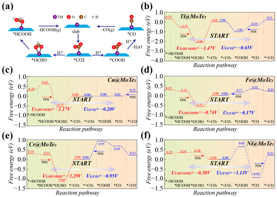
Figure 2.
(a) Pathway of the CO2 reduction to HCOOH and CO. (b–f) Free energy diagrams of the electro-catalytic CO2RR on Ti, Cu, Fe, Cr, and Ni@MoTe2 (* represents substrate material).
Figure 2b–f present the Gibbs free energy profiles of various adsorbed intermediates during the protonation of CO2RR to CO and HCOOH by the aforementioned systems. In Figure 2b, the potential-determining step (PDS) for the reduction of CO2 to HCOOH on Ti@MoTe2 is the protonation of *OCHO, with a free energy barrier of 1.47 eV. The PDS for the reduction of CO2 to CO is the protonation of *COOH to form CO, with a free energy barrier of 0.65 eV. The first protonation steps for the production of both HCOOH and CO exhibit a downward energy trend. However, the free energy barrier of the intermediate *OCHO is lower than that of *COOH, which favors the formation of HCOOH and reduces the efficiency of CO product formation. Similarly, for Cu@MoTe2, the initial protonation steps in both pathways are not energetically uphill, with *OCHO exhibiting lower energy, as shown in Figure 2c. The key difference lies in the PDS for CO2 reduction to CO, which is the desorption of *CO with a limiting potential of only −0.20 V, while the limiting potential for HCOOH formation is −1.17 V. For the Fe@MoTe2 in Figure 2d and Cr@MoTe2 in Figure 2e, the limiting potentials for the reduction of CO2 to HCOOH (CO) are −0.74 V (−0.17 V) and −1.29 V (−0.95 V), respectively. Similarly, the first protonation step for HCOOH formation exhibits a lower energy barrier, while the first protonation step for CO formation is energetically uphill, unlike Ti@MoTe2 and Cu@MoTe2. Figure 2f indicates that, for Ni@MoTe2, the PDS for the reduction of CO2 to HCOOH is the initial protonation of CO2, with a free energy difference of 0.38 eV. The PDS for CO2 reduction to CO involves the desorption of CO, with a free energy difference of 1.13 eV. The initial protonation is more likely to proceed through the lower free energy intermediate *OCHO. Therefore, we infer that Ni@MoTe2 is more favorable for promoting the reduction of CO2 to HCOOH.
We further investigated the relationship between the Gibbs free energy of key intermediates and the limiting potential of the corresponding products. Figure 3a illustrates the relationship between UL(CO) and G*COOH, revealing a volcano plot. Near the zero of G*COOH, Cu@MoTe2 and Fe@MoTe2 are positioned at the volcano top, exhibiting lower limiting potential and demonstrating good catalytic activity. In Figure 3b, UL(HCOOH) and G*OCHO exhibit a linear relationship. When the G*OCHO approaches zero, Ni@MoTe2 shows the optimal limiting potential. The above results indicate that G*COOH and G*OCHO can serve as the limiting potential descriptors.
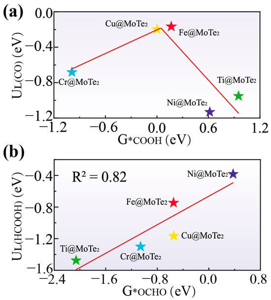
Figure 3.
(a) Volcanic relationship diagram between G*COOH and UL(CO). (b) Linear relationship diagram between G*OCHO and UL(HCOOH).
2.3. Selectivity Analysis
For an excellent catalyst, high activity alone is insufficient; the selectivity must also be considered. Selectivity primarily considers the competition with the hydrogen evolution reaction (HER). Since both CO2 reduction and HER involve the activity of hydrogen ions (protons) under reaction conditions, HER might compete with CO2 electro-catalysis and leads to the decrease of the activity of CO2RR [41].
Figure 4a presents the free energy diagrams for the HER on the five TM@MoTe2 (TM = Ti, Cr, Ni, Fe, and Cu) systems. It can be observed that Fe@MoTe2 and Cr@MoTe2 exhibit good activity for HER, with limiting potentials of only −0.03 eV and −0.12 eV, respectively, indicating their potential as effective catalysts for HER. On the other hand, Ni@MoTe2, Cu@MoTe2, and Ti@MoTe2 exhibit relatively high limiting potentials, indicating lower activity for HER. Figure 4b provides a visual comparison of the relative selectivity towards the competitive HER for the five systems during CO2 reduction. In the upper left corner of the diagram (orange region), the reaction favors CO2 reduction, while the lower right corner (blue region) signifies a preference for HER. Among the ten different CO2RR processes, only Ni@MoTe2(HCOOH) and Cu@MoTe2(CO) exhibit good selectivity towards CO2RR, while the results of the other materials are located in the blue region. For the CO2RR of Ni@MoTe2(HCOOH) and Cu@MoTe2(CO), the calculated Faradaic efficiency (FE) is about 87.7% and 99.6%, respectively (the calculation formula for the FE can be found in Supporting Material, Note S1).
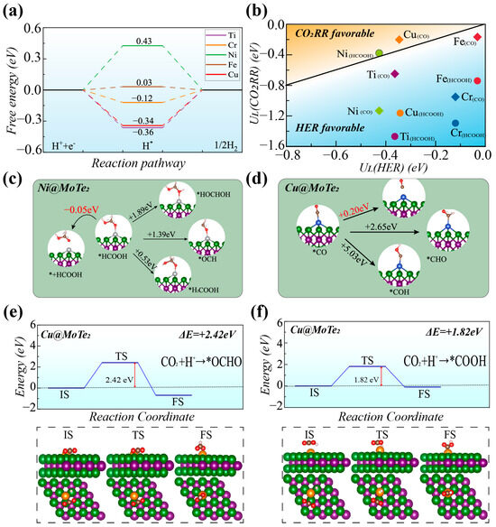
Figure 4.
(a) Free energy diagram for HER on TM@MoTe2 (TM = Ti, Cr, Ni, Fe, and Cu). (b) Limiting potentials of CO2RR and HER on TM@MoTe2. The orange region (upper-left side) is CO2RR dominant. (c,d) Possible intermediates and products for further protonation of *HCOOH on Ni@MoTe2 (c) and *CO on Cu@MoTe2 (d). (e,f) Transition state (TS) energy barriers and corresponding TS structures for the conversion of CO2 to *OCHO (e) and *COOH (f) on Cu@MoTe2 (* represents substrate material).
Due to the excellent selectivity of Ni@MoTe2 and Cu@MoTe2, we further analyzed the potential subsequent reactions of their products, *HCOOH and *CO. *HCOOH can undergo subsequent desorption or further protonation to form *HOCHOH, *OCH, or *H2COOH intermediates. As shown in Figure 4c, the desorption energy of *HCOOH on Ni@MoTe2 is approximately −0.05 eV. As a comparison, its subsequent protonation to form *HOCHOH, *OCH, and *H2COOH intermediates is about +1.89 eV, +1.39 eV, and +0.53 eV, respectively. Hence, the protonation of *HCOOH to form *HOCHOH, *OCH, or *H2COOH requires relatively high energy inputs, while the desorption of HCOOH is an exothermic process that requires no thermodynamic barrier. Consequently, Ni@MoTe2 tends to desorb HCOOH and suppress the formation of various other products. As shown in Figure 4d, the free energy barrier for *CO desorption on Cu@MoTe2 is +0.20 eV, while the energy barriers for further protonation to form the *CHO and *COH intermediates are +2.65 eV and +5.03 eV, respectively. Although the desorption of *CO results in an increase in free energy, it is evidently more favorable for *CO to desorb to form the CO product compared to the formation of the *CHO and *COH intermediates. Therefore, both Cu@MoTe2 and Ni@MoTe2 not only exhibit high activity and selectivity but also tend to generate target products without introducing unrelated intermediates.
The generation of CO on Cu@MoTe2 exhibits a low limiting potential (−0.20 V) and good selectivity. However, from the perspective of the free energy difference, Cu@MoTe2 has lower energy for the *OCHO intermediate in the first hydrogenation step, which may lead to reduced efficiency in the production of CO. We further calculated the energy barriers of transition states using the CI-NEB method to analyze product selectivity from the reaction rate perspective [33]. In Figure 4e,f, we calculated the transition states for the two reaction processes: *CO2 + H+ + e− → *OCHO and *CO2 + H+ + e− → *COOH on Cu@MoTe2. Although the transition state for the formation of *OCHO has a lower final state energy, it must overcome a higher energy barrier of 2.42 eV, which is greater than the 1.82 eV barrier that the formation of *COOH must surpass. The relatively low energy barrier makes CO generation on Cu@MoTe2 feasible. Therefore, Cu@MoTe2 may serve as a reference for the potential candidate catalysts.
2.4. Mechanism of CO2 Activation
To further understand the activation mechanism of CO2, we present the projected crystal orbital Hamiltonian population (PCOHP) of CO2 on Ni@MoTe2 and Cu@MoTe2 substrates [42], as shown in Figure 5a,b. In the figure, we use -PCOHP. The red curve on the right represents bonding states, with peaks located below the Fermi level (EF), indicating that they are fully occupied by electrons. The blue curve on the left represents antibonding states, some of which are partially filled with electrons. The integrated crystal orbital Hamilton population (ICOHP) value for the C-O bond awaiting hydrogenation is −14.46 eV on Ni@MoTe2 and −15.94 eV on Cu@MoTe2, respectively. The ICOHP values on the remaining three systems, Ti@MoTe2, Cr@MoTe2, and Fe@MoTe2, are −11.79 eV, −14.44 eV, and −15.64 eV, respectively (Figure S17 in Supporting Material). The ICOHP value of the C-O bond in the free CO2 gas molecule is about −18.45 eV, which indicates that CO2 adsorbed on these five substrates will be activated to a great extent compared with free CO2. The C-O bond lengths upon hydrogenation on TM@MoTe2 (TM = Fe, Cu, Ni, Cr, and Ti) are 1.21 Å, 1.21 Å, 1.24 Å, 1.26 Å, and 1.35 Å, respectively. The higher the ICOHP value, the longer the corresponding C-O bond length upon hydrogenation, indicating more pronounced activation.
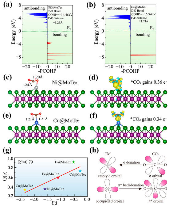
Figure 5.
(a,b) -PCOHP of adsorbed CO2 on Ni@MoTe2 (a) and Cu@MoTe2 (b). The ICOHP and the C-O bond length are also marked in figures. (c,d) Structure of CO2 adsorbed on Ni@MoTe2 (c) and its corresponding charge density plot (d). (e,f) Structure of CO2 adsorbed on Cu@MoTe2 (e) and its corresponding charge density plot (f). (g) Relationship between the d-band center and the charge obtained by CO2. (h) Simplified mechanism diagram of CO2 bonding and activation on TM atoms.
Figure 5c–f and Figure S18 show the structures of CO2 adsorbed on TM@MoTe2 and the corresponding charge density plots, where blue represents electron depletion and yellow represents electron accumulation. From these figures, we can observe that different amounts of electron exchange occur between CO2 and the substrates. The transferred charges to CO2 on TM@MoTe2 (TM = Cu, Ni, Fe, Cr, and Ti) are calculated to be 0.34 e, 0.36 e, 0.59 e, 0.69 e, and 0.94 e, respectively. Herein, both Ti and Cr exhibit significant electron transfer to CO2 and form bonds with both oxygen atoms of CO2. On the MoTe2 surface, Ti and Cr exist in relatively low oxidation states, enabling more electron donation to the O atoms of CO2. This partial occupation of CO2’s π* orbitals facilitates the bent (inverted V-shaped) activation of CO2. Figure 5g illustrates the relationship between the charge transfer on CO2 and the center of the d-band. According to the classical d-band center theory, the d-band center of the catalyst surface determines the strength of the interaction between the metal and the reactant [43]. The figure shows that there is a strong linear relationship between the amount of charge transferred on CO2 and the center of d-band, which is consistent with the d-band theory. By modulating the d-band center, the activation of CO2 can be effectively controlled. The transferred charge on Fe@MoTe2 is moderate, and the corresponding generations of HCOOH and CO on Fe@MoTe2 have relatively low limiting potentials. This is consistent with the Sabatier principle [44], which suggests that optimal catalytic activity is typically achieved when the interaction between the intermediate and the substrate is neither too weak nor too strong.
To better understand the activation mechanism, Figure 5h illustrates the interaction between CO2 and substrate. Upon CO2 adsorption, the lone pair electrons in the σ orbital of CO2 engage in σ donation to the vacant d orbitals of the TM atom, occupying the empty d orbitals of the TM atom [45]. Simultaneously, the occupied d orbitals of the TM atom participate in π* back-donation, populating the π* antibonding orbitals of the CO2 molecule. These insights shed light on the intricate interplay between CO2 and the substrate, revealing the mechanistic basis for the diverse adsorption strengths observed in CO2-derived critical intermediates.
3. Computational Methodology
All computations were carried out utilizing the spin-polarized density functional theory (DFT) methodology implemented in the Vienna Ab-initio Simulation Package (VASP 5.4.4) [46]. The electron–ion interactions were modeled using the projector-augmented wave (PAW) approach, while the electronic exchange and correlation effects were described using the Perdew–Burke–Ernzerhof (PBE) functional within the framework of the generalized gradient approximation (GGA) [47,48]. To account for van der Waals (vdW) interactions between reactants, intermediates, and catalysts, the empirical correction scheme based on the Grimme method (DFT + D3) was employed [49]. The transition states involved were systematically explored by employing the climbing-image nudged elastic band (CI-NEB) method [50]. A plane wave energy cutoff of 400 eV was employed for structural optimizations, while a value of 500 eV was chosen for electronic structure calculations. The k-point grids were set to 1 × 1 × 1 for geometry optimization and 5 × 5 × 1 for electronic structure calculations. Convergence criteria for electronic energy and forces were established at 10−5 eV and 0.05 eV/Å, respectively. Additionally, an 18 Å vacuum layer was introduced to mitigate interlayer interactions. Catalyst thermal stability was assessed through ab initio molecular dynamics (AIMD) simulations using VASP, with a Nose–Hoover thermostat employed. The selected materials were expanded to a 2 × 2 × 1 supercell. A time step of 3 fs and a total simulation duration of 9 ps were selected to verify the thermal stability of catalysts.
To ascertain the Gibbs free energy during proton transfer in CO2RR, computations were conducted utilizing a computational hydrogen electrode (CHE) model [51,52]. The Gibbs free energies (G) for all intermediate steps were determined using the following equation: ; here, E corresponds to the energy of surface and intermediate species obtained from DFT calculations, ΔZPE represents the variation in zero-point energy, and ΔS accounts for the entropy change of free molecules and adsorbates at 298.15 K. The pH-dependent GpH was calculated using the formula ; here, kB stands for the Boltzmann constant, and pH was set to zero. The limiting potential (UL) was determined as UL = −ΔGmax/|e|, where ΔGmax denotes the difference in free energy of the highest energy step on the reaction pathway, and e represents the unit of charge. Smaller |UL| corresponds to higher activity level.
4. Conclusions
This study primarily presents a theoretical and computational investigation. In this work, using MoTe2 as the substrate material, we considered six transition metals (TM = Ti, Cr, Fe, Ni, Cu, and Zn) anchored to the surface of MoTe2 as candidates for novel CO2RR catalysts. After the stability analysis of the substrate material, the Zn atom was excluded from further consideration due to the inability to anchor effectively on MoTe2. Through comprehensive study, Cu@MoTe2 and Fe@MoTe2 exhibit low limiting potentials for CO2 reduction to CO, with values of 0.20 eV and 0.17 eV, respectively. In addition, Ni@MoTe2 exhibits excellent activity for CO2 reduction to HCOOH, with a limiting potential of 0.38 eV. The key intermediates *COOH and *OCHO can serve as descriptors to predict the limiting potentials for the formation of CO and HCOOH. After selective screening, Ni@MoTe2 exhibits excellent selectivity for CO2 reduction to HCOOH, with a Faradaic efficiency (FE) of 88.7%. The CO2RR on Cu@MoTe2 may be influenced by the hydrogenation free energy in the first step, where the free energy of the *COOH intermediate is higher than that of *OCHO. The formation of CO on Cu@MoTe2 may be affected. However, transition state analysis reveals that the lower energy barrier for *COOH makes CO generation on Cu@MoTe2 possible. The FE for the CO2RR on Cu@MoTe2 is as high as 99.6%. Since the results of this study primarily rely on computational simulations, these findings are model-based. We hope that our calculations will contribute to the design and synthesis of high-performance catalysts based on MoTe2.
Supplementary Materials
The following supporting information can be downloaded at: https://www.mdpi.com/article/10.3390/catal15040377/s1, Note S1: Faradaic efficiency of CO2RR. Table S1: TM@MoTe2 (TM = Ti, Cr, Fe, Ni, Cu) systems: Bader charges, atomic radii, charge densities, and binding energies of TM atoms. A positive sign indicates electron loss (positive oxidation state). Figure S1: Optimized adsorption configurations of Cr, Cu, Ni, Ti, Fe, Zn as well as pure MoTe2 on the T1 site. Figure S2: Aggregation energies of 2, 3, and 4 Ni atoms on MoTe2 and their corresponding transition state structures. Figure S3: ELF of Cr, Cu, Fe, Ti, and pure MoTe2 on the T1 site. The red dashed line represents the selected plane. Figure S4: (a) Band structures of MoTe2. (b–f) Band structures of Ti (b), Cr (c), Fe (d), Ni (e), and Cu@MoTe2 (f). Figure S5: Energy and temperature versus time for Ni@MoTe2 and Cu@MoTe2 in AIMD simulation at 300 K. Figure S6: Optimized adsorption configurations of CO2 on the Cr, Cu, Fe, Ni, and Ti@MoTe2. Figure S7: The flow chart of electrocatalytic reduction of CO2 to CO on Cr@MoTe2. Figure S8: The flow chart of electrocatalytic reduction of CO2 to CO on Cu@MoTe2. Figure S9: The flow chart of electrocatalytic reduction of CO2 to CO on Fe@MoTe2. Figure S10: The flow chart of electrocatalytic reduction of CO2 to CO on Ni@MoTe2. Figure S11: The flow chart of electrocatalytic reduction of CO2 to CO on Ti@MoTe2. Figure S12: Flow chart of electrocatalytic reduction of CO2 to HCOOH on Cr@MoTe2. Figure S13: The flow chart of electrocatalytic reduction of CO2 to HCOOH on Cu@MoTe2. Figure S14: The flow chart of electrocatalytic reduction of CO2 to HCOOH on Fe@MoTe2. Figure S15: The flow chart of electrocatalytic reduction of CO2 to HCOOH on Ni@MoTe2. Figure S16: The flow chart of electrocatalytic reduction of CO2 to HCOOH on Ti@MoTe2. Figure S17: -PCOHP and bond length between C and O atoms of CO2 adsorbed on Ti, Cr, Fe@MoTe2. Figure S18: The structure of CO2 adsorbed on TM@MoTe2 (TM = Ti, Cr, Fe) and their corresponding charge density maps. Yellow and cyan colors denote the consumption and accumulation of electron, respectively. The isosurface value is set as 0.03 e/Å3.
Author Contributions
Conceptualization, B.Z., J.W., R.W. and Z.L.; Methodology, B.Z., J.W. and R.W.; Formal analysis, B.Z., J.W., R.W. and Z.L.; Investigation, Z.L.; Writing—original draft, B.Z.; Writing—review & editing, Z.L.; Supervision, Z.L. All authors have read and agreed to the published version of the manuscript.
Funding
This research received no external funding.
Data Availability Statement
The data supporting this article have been included as part of the Supplementary Information.
Acknowledgments
This work is supported by High Performance Computing Center, University of Shanghai for Science and Technology.
Conflicts of Interest
The authors declare no conflicts of interest.
References
- Chu, S.; Cui, Y.; Liu, N. The path towards sustainable energy. Nat. Mater. 2017, 16, 16–22. [Google Scholar] [CrossRef] [PubMed]
- Nørskov, J.K.; Weckhuysen, B.; Centi, G.; ChorkendorffI, S.R.; Marin, G.; Grimaud, A.; Rossmeisl, J.; Strasser, P.; Koper, M.; Roldan, B. Research Needs Towards Sustainable Production of Fuels and Chemicals; Energy Exploration Technologies: San Juan, Puerto Rico, 2019. [Google Scholar]
- Shen, J.; Kortlever, R.; Kas, R.; Birdja, Y.Y.; Diaz-Morales, O.; Kwon, Y.; Ledezma-Yanez, I.; Schouten, K.J.P.; Mul, G.; Koper, M.T.M. Electrocatalytic reduction of carbon dioxide to carbon monoxide and methane at an immobilized cobalt protoporphyrin. Nat. Commun. 2015, 6, 8117. [Google Scholar] [CrossRef]
- Kornienko, N.; Zhao, Y.; Kley, C.S.; Zhu, C.; Kim, D.; Lin, S.; Chang, C.J.; Yaghi, O.M.; Yang, P. Metal-organic frameworks for electrocatalytic reduction of carbon dioxide. J. Am. Chem. Soc. 2015, 137, 14129–14135. [Google Scholar] [CrossRef]
- Klinkova, A.; De Luna, P.; Dinh, C.-T.; Voznyy, O.; Larin, E.M.; Kumacheva, E.; Sargent, E.H. Rational Design of Efficient Palladium Catalysts for Electroreduction of Carbon Dioxide to Formate. ACS Catal. 2016, 6, 8115–8120. [Google Scholar] [CrossRef]
- Whipple, D.T.; Kenis, P.J.A. Prospects of CO2 Utilization via Direct Heterogeneous Electrochemical Reduction. J. Phys. Chem. Lett. 2010, 1, 3451–3458. [Google Scholar] [CrossRef]
- Zhang, Y.; Mo, Y.; Cao, Z. Rational Design of Main Group Metal-Embedded Nitrogen-Doped Carbon Materials as Frustrated Lewis Pair Catalysts for CO2 Hydrogenation to Formic Acid. ACS Appl. Mater. Interfaces 2022, 14, 1002–1014. [Google Scholar] [CrossRef]
- Zhu, D.D.; Liu, J.L.; Qiao, S.Z. Recent Advances in Inorganic Heterogeneous Electrocatalysts for Reduction of Carbon Dioxide. Adv. Mater. 2016, 28, 3423–3452. [Google Scholar] [CrossRef]
- Wang, L.; Chen, W.; Zhang, D.; Du, Y.; Amal, R.; Qiao, S.; Wu, J.; Yin, Z. Surface strategies for catalytic CO2 reduction: From two-dimensional materials to nanoclusters to single atoms. Chem. Soc. Rev. 2019, 48, 5310–5349. [Google Scholar] [CrossRef]
- Lü, F.; Bao, H.; Mi, Y.; Liu, Y.; Sun, J.; Peng, X.; Qiu, Y.; Zhuo, L.; Liu, X.; Luo, J. Electrochemical CO2 reduction: From nanoclusters to single atom catalysts. Sustain. Energy Fuels 2020, 4, 1012–1028. [Google Scholar] [CrossRef]
- Zhang, X.; Guo, S.-X.; Gandionco, K.A.; Bond, A.M.; Zhang, J. Electrocatalytic carbon dioxide reduction: From fundamental principles to catalyst design. Mater. Today Adv. 2020, 7, 100074. [Google Scholar] [CrossRef]
- Ao, C.; Feng, B.; Qian, S.; Wang, L.; Zhao, W.; Zhai, Y.; Zhang, L. Theoretical study of transition metals supported on g-C3N4 as electrochemical catalysts for CO2 reduction to CH3OH and CH4. J. CO2 Util. 2020, 36, 116–123. [Google Scholar] [CrossRef]
- He, T.; Zhang, L.; Kour, G.; Du, A. Electrochemical reduction of carbon dioxide on precise number of Fe atoms anchored graphdiyne. J. CO2 Util. 2020, 37, 272–277. [Google Scholar] [CrossRef]
- Zhang, Y.; Zhao, Y.; Wang, C.; Wei, Z.; Yang, J.; Ma, J. Zn-Doped Cu100 facet with efficient catalytic ability for the CO2 electroreduction to ethylene. Phys. Chem. Chem. Phys. 2019, 21, 21341–21348. [Google Scholar] [CrossRef] [PubMed]
- Karmodak, N.; Vijay, S.; Kastlunger, G.; Chan, K. Computational Screening of Single and Di-Atom Catalysts for Electrochemical CO2 Reduction. ACS Catal. 2022, 12, 4818–4824. [Google Scholar] [CrossRef]
- Kapse, S.; Narasimhan, S.; Thapa, R. Descriptors and graphical construction for in silico design of efficient and selective single atom catalysts for the eNRR. Chem. Sci. 2022, 13, 10003–10010. [Google Scholar] [CrossRef]
- Cao, S.; Liu, Y.; Hu, Y.; Li, J.; Yang, C.; Chen, Z.; Wang, Z.; Wei, S.; Liu, S.; Lu, X. Precise electronic structure modulation on MXene-based single atom catalysts for high-performance electrocatalytic CO2 reduction reaction: A first-principle study. J. Colloid Interface Sci. 2023, 642, 273–282. [Google Scholar] [CrossRef]
- Cheng, Y.; Xu, X.; Li, Y.; Zhang, Y.; Song, Y. CO2 reduction mechanism on the Nb2CO2 MXene surface: Effect of nonmetal and metal modification. Comput. Mater. Sci. 2022, 202, 110971. [Google Scholar] [CrossRef]
- Detz, H.; Butera, V. Insights into the mechanistic CO2 conversion to methanol on single Ru atom anchored on MoS2 monolayer. Mol. Catal. 2023, 535, 112878. [Google Scholar] [CrossRef]
- Doulassiramane, T.; Arumugam, N.; Almansour, A.I.; Mahalingam, S.M.; Padmanaban, R. An effective strategy for CO2 reduction to C1 products using Cu-embedded MoS2 electrocatalyst: DFT study. New J. Chem. 2023, 47, 6932–6942. [Google Scholar] [CrossRef]
- Jiang, J.; Zou, X.; Mei, Z.; Cai, S.; An, Q.; Fu, Y.; Wang, H.; Liu, T.; Guo, H. Understanding rich oxygen vacant hollow CeO2@MoSe2 heterojunction for accelerating photocatalytic CO2 reduction. J. Colloid Interface Sci. 2022, 611, 644–653. [Google Scholar] [CrossRef]
- Linghu, Y.; Tong, T.; Li, C.; Wu, C. The catalytic mechanism of CO2 electrochemical reduction over transition metal-modified 1T’-MoS2 monolayers. Appl. Surf. Sci. 2022, 590, 153001. [Google Scholar] [CrossRef]
- Liu, X.; Yang, H.; He, J.; Liu, H.; Song, L.; Li, L.; Luo, J. Highly Active, Durable Ultrathin MoTe2 Layers for the Electroreduction of CO2 to CH4. Small 2018, 14, e1704049. [Google Scholar] [CrossRef] [PubMed]
- Lu, Z.; Cheng, Y.; Li, S.; Yang, Z.; Wu, R. CO2 thermoreduction to methanol on the MoS2 supported single Co atom catalyst: A DFT study. Appl. Surf. Sci. 2020, 528, 147047. [Google Scholar] [CrossRef]
- Zhang, Y.; Yang, R.; Li, H.; Zeng, Z. Boosting Electrocatalytic Reduction of CO2 to HCOOH on Ni Single Atom Anchored WTe2 Monolayer. Small 2022, 18, e2203759. [Google Scholar] [CrossRef]
- Deng, Y.; Zhao, X.; Zhu, C.; Li, P.; Duan, R.; Liu, G.; Liu, Z. MoTe2: Semiconductor or Semimetal? ACS Nano 2021, 15, 12465–12474. [Google Scholar] [CrossRef]
- Kim, H.; Bhang, J.; Park, T.; Lee, J.-H.; Seo, H.; Yoo, Y. Elucidating atomistic mechanisms of the formation of phase-controlled ultrathin MoTe2 films and lateral hetero-phase MoTe2 interfaces. Surf. Interfaces 2023, 40, 103040. [Google Scholar] [CrossRef]
- Tan, Y.; Luo, F.; Zhu, M.; Xu, X.; Ye, Y.; Li, B.; Wang, G.; Luo, W.; Zheng, X.; Wu, N.; et al. Controllable 2H-to-1T’ phase transition in few-layer MoTe2. Nanoscale 2018, 10, 19964–19971. [Google Scholar] [CrossRef]
- Pedersen, P.D.; Melander, M.M.; Bligaard, T.; Vegge, T.; Honkala, K.; Hansen, H.A. Grand Canonical DFT Investigation of the CO2RR and HER Reaction Mechanisms on MoTe2 Edges. J. Phys. Chem. C 2023, 127, 18855–18864. [Google Scholar] [CrossRef]
- Bagger, A.; Ju, W.; Varela, A.S.; Strasser, P.; Rossmeisl, J. Electrochemical CO2 Reduction: A Classification Problem. Nat. Commun. 2017, 18, 3266–3273. [Google Scholar] [CrossRef]
- Fu, L.; Wang, R.; Zhao, C.; Huo, J.; He, C.; Kim, K.-H.; Zhang, W. Construction of Cr-embedded graphyne electrocatalyst for highly selective reduction of CO2 to CH4: A DFT study. Chem. Eng. J. 2021, 414, 128857. [Google Scholar] [CrossRef]
- Manzeli, S.; Ovchinnikov, D.; Pasquier, D.; Yazyev, O.V.; Kis, A. 2D transition metal dichalcogenides. Nat. Rev. Mater. 2017, 2, 17033. [Google Scholar] [CrossRef]
- Guo, Z.; Wang, L.; Han, M.; Zhao, E.; Zhu, L.; Guo, W.; Tan, J.; Liu, B.; Chen, X.-Q.; Lin, J. One-step growth of bilayer 2H–1T′ MoTe2 van der Waals heterostructures with interlayer-coupled resonant phonon vibration. ACS Nano 2022, 16, 11268–11277. [Google Scholar] [CrossRef] [PubMed]
- Jones, L.A.H.; Xing, Z.; Swallow, J.E.N.; Shiel, H.; Featherstone, T.J.; Smiles, M.J.; Fleck, N.; Thakur, P.K.; Lee, T.-L.; Hardwick, L.J.; et al. Band Alignments, Electronic Structure, and Core-Level Spectra of Bulk Molybdenum Dichalcogenides (MoS2, MoSe2, and MoTe2). J. Phys. Chem. C 2022, 126, 21022–21033. [Google Scholar] [CrossRef]
- Huang, H.H.; Fan, X.; Singh, D.J.; Chen, H.; Jiang, Q.; Zheng, W.T. Controlling phase transition for single-layer MTe2 (M = Mo and W): Modulation of the potential barrier under strain. Phys. Chem. Chem. Phys. 2016, 18, 4086–4094. [Google Scholar] [CrossRef]
- Rawat, A.; Jena, N.; Dimple, D.; De Sarkar, A. A comprehensive study on carrier mobility and artificial photosynthetic properties in group VI B transition metal dichalcogenide monolayers. J. Mater. Chem. A 2018, 6, 8693–8704. [Google Scholar] [CrossRef]
- Lin, Y.F.; Xu, Y.; Wang, S.T.; Li, S.L.; Yamamoto, M.; Aparecido-Ferreira, A.; Li, W.; Sun, H.; Nakaharai, S.; Jian, W.B.; et al. Ambipolar MoTe2 transistors and their applications in logic circuits. Adv. Mater. 2014, 26, 3263–3269. [Google Scholar] [CrossRef]
- Ruppert, C.; Aslan, B.; Heinz, T.F. Optical properties and band gap of single- and few-layer MoTe2 crystals. Nano Lett. 2014, 14, 6231–6236. [Google Scholar] [CrossRef]
- Pradhan, N.R.; Rhodes, D.; Feng, S.; Xin, Y.; Memaran, S.; Moon, B.H.; Terrones, H.; Terrones, M.; Balicas, L. Field-effect transistors based on few-layered alpha-MoTe2. ACS Nano 2014, 8, 5911–5920. [Google Scholar] [CrossRef]
- Zheng, W.; Wang, C.; Chen, J.; Chen, S.; Lin, Z.; Huang, M.; Huang, H.; Qu, Y.; Wang, P.; Hu, L. Highly selective electrocatalytic reduction of CO2 to HCOOH over an in situ derived Ag-loaded Bi2O2CO3 electrocatalyst. Dalton Trans. 2024, 53, 4617–4623. [Google Scholar] [CrossRef]
- Chan, K.; Tsai, C.; Hansen, H.A.; Nørskov, J.K. Molybdenum sulfides and selenides as possible electrocatalysts for CO2 reduction. ChemCatChem 2014, 6, 1899–1905. [Google Scholar] [CrossRef]
- Nelson, R.; Ertural, C.; George, J.; Deringer, V.L.; Hautier, G.; Dronskowski, R. LOBSTER: Local orbital projections, atomic charges, and chemical-bonding analysis from projector-augmented-wave-based density-functional theory. J. Comput. Chem. 2020, 41, 1931–1940. [Google Scholar] [CrossRef] [PubMed]
- Hammer, B.; Nørskov, J.K. Electronic factors determining the reactivity of metal surfaces. Surf. Sci. 1995, 343, 211–220. [Google Scholar] [CrossRef]
- Nørskov, J.K.; Bligaard, T.; Logadottir, A.; Kitchin, J.; Chen, J.G.; Pandelov, S.; Stimming, U. Trends in the exchange current for hydrogen evolution. J. Electrochem. Soc. 2005, 152, J23. [Google Scholar] [CrossRef]
- Zheng, W.; Yang, J.; Chen, H.; Hou, Y.; Wang, Q.; Gu, M.; He, F.; Xia, Y.; Xia, Z.; Li, Z. Atomically defined undercoordinated active sites for highly efficient CO2 electroreduction. Adv. Funct. Mater. 2020, 30, 1907658. [Google Scholar] [CrossRef]
- Kresse, G.; Furthmüller, J. Efficiency of ab-initio total energy calculations for metals and semiconductors using a plane-wave basis set. Comput. Mater. Sci. 1996, 6, 15–50. [Google Scholar] [CrossRef]
- Blochl, P.E. Projector augmented-wave method. Phys. Rev. B 1994, 50, 17953–17979. [Google Scholar] [CrossRef]
- Perdew, J.P.; Burke, K.; Ernzerhof, M. Generalized Gradient Approximation Made Simple. Phys. Rev. Lett. 1996, 77, 3865–3868. [Google Scholar] [CrossRef]
- Grimme, S. Semiempirical GGA-type density functional constructed with a long-range dispersion correction. J. Comput. Chem. 2006, 27, 1787–1799. [Google Scholar] [CrossRef]
- Henkelman, G.; Uberuaga, B.P.; Jónsson, H. A climbing image nudged elastic band method for finding saddle points and minimum energy paths. J. Chem. Phys. 2000, 113, 9901–9904. [Google Scholar] [CrossRef]
- Gao, J.; Cheng, L.; Li, K.; Wang, Y.; Wu, Z. Electrochemical CO2 Reduction on Two-Dimensional Metal 1, 3, 5-triamino-2, 4, 6-Benzenetriol Frameworks: A Density Functional Study. J. Electrochem. Soc. 2022, 169, 024513. [Google Scholar] [CrossRef]
- He, M.; An, W.; Wang, Y.; Men, Y.; Liu, S. Hybrid metal–boron diatomic site embedded in C2N monolayer promotes C–C coupling in CO2 electroreduction. Small 2021, 17, 2104445. [Google Scholar] [CrossRef]
Disclaimer/Publisher’s Note: The statements, opinions and data contained in all publications are solely those of the individual author(s) and contributor(s) and not of MDPI and/or the editor(s). MDPI and/or the editor(s) disclaim responsibility for any injury to people or property resulting from any ideas, methods, instructions or products referred to in the content. |
© 2025 by the authors. Licensee MDPI, Basel, Switzerland. This article is an open access article distributed under the terms and conditions of the Creative Commons Attribution (CC BY) license (https://creativecommons.org/licenses/by/4.0/).