Article

Carbon-Coated Magnetic Catalysts for Enhanced Degradation of Nitrophenols: Stability and Efficiency in Catalytic Wet Peroxide Oxidation

by
Arthur P. Baldo
1,
Ana Júlia B. Bezerra
1,
Adriano S. Silva
1,*,
Ana Paula Ferreira
1,2,
Fernanda F. Roman
1,
Ihsan Çaha
3,
Manuel Bañobre-López
3,
Francis Leonard Deepak
3 and
Helder T. Gomes
1,*
1
CIMO, LA SusTEC, Instituto Politécnico de Bragança, Campus de Santa Apolónia, 5300-253 Bragança, Portugal
2
Chemistry Center of Vila Real (CQVR), University of Trás-os-Montes and Alto Douro, Quinta de Prados, 5000-801 Vila Real, Portugal
3
International Iberian Nanotechnology Laboratory (INL), Avenida Mestre Jose Veiga, 4715-330 Braga, Portugal
*
Authors to whom correspondence should be addressed.
Catalysts 2025, 15(4), 376; https://doi.org/10.3390/catal15040376
Submission received: 11 March 2025 / Revised: 8 April 2025 / Accepted: 10 April 2025 / Published: 11 April 2025
(This article belongs to the Special Issue Carbon-Based Catalysts to Address Environmental Challenges)

Abstract

:
Nitrophenols are persistent organic pollutants that pose serious environmental and health risks due to their toxic and lipophilic nature. Their persistence arises from strong aromatic stability and resistance to biodegradation, while their lipophilicity facilitates bioaccumulation, exacerbating ecological and human health concerns. To address this challenge, this study focuses on the synthesis and characterization of two different types of hybrid multi-core magnetic catalysts: (i) cobalt ferrite (Co-Fe2O4), which exhibits ferrimagnetic properties, and (ii) magnetite (Fe3O4), which demonstrates close superparamagnetic behavior and is coated with a novel and less hazardous phloroglucinol–glyoxal-derived resin. This approach aims to enhance catalytic efficiency while reducing the environmental impact, offering a sustainable solution for the degradation of nitrophenols in aqueous matrices. Transmission electron microscopy (TEM) images revealed the formation of a multi-core shell structure, with carbon layer sizes of 6.6 ± 0.7 nm for cobalt ferrite and 4.2 ± 0.2 nm for magnetite. The catalysts were designed to enhance the stability and performance in catalytic wet peroxide oxidation (CWPO) processes using sol–gel and solution combustion synthesis methods, respectively. In experiments of single-component degradation, the carbon-coated cobalt ferrite (CoFe@C) catalyst achieved 90% removal of 2-nitrophenol (2-NP) and 96% of 4-nitrophenol (4-NP), while carbon-coated magnetite (Fe3O4@C) demonstrated similar efficiency, with 86% removal of 2-NP and 94% of 4-NP. In the multi-component system, CoFe@C exhibited the highest catalytic activity, reaching 96% removal of 2-NP, 99% of 4-NP, and 91% decomposition of H2O2. No leaching of iron was detected in the coated catalysts, whereas the uncoated materials exhibited similar and significant leaching (CoFe: 5.66 mg/L, Fe3O4: 12 mg/L) in the single- and multi-component system. This study underscores the potential of hybrid magnetic catalysts for sustainable environmental remediation, demonstrating a dual-function mechanism that enhances catalytic activity and structural stability.

1. Introduction

The growing global population and increasing industrialization have greatly impacted the availability of clean water [1]. As both human populations and economic activities continue to expand, this challenge is expected to persist and worsen [2]. Nitrophenols (NPs), including mono-, di-, and tri-nitrophenols, are recognized for their hydrophobic [1,3], highly toxic [4], and inhibitory nature [5]. These organic compounds are commonly used in various industries, such as plastic production [6], pigments [7], herbicides [8], and petroleum plants [9]. Among them, 2-nitrophenol (2-NP) and 4-nitrophenol (4-NP) are structural isomers with different hydrophobic characteristics due to the position of the nitro group relative to the hydroxyl group [10], which interferes with conventional biological wastewater treatment methods [11]. However, advanced oxidation techniques, such as catalytic wet peroxide oxidation (CWPO) [12], have shown promising potential in degrading persistent organic pollutants [2,13].
Thus, chemical oxidation processes offer a promising alternative to conventional treatment methods by breaking down nitrophenols (NPs) into less toxic compounds without the need for prior extraction or pre-treatment [5]. CWPO operates by generating hydroxyl radicals (HO) through the catalytic decomposition of hydrogen peroxide (H2O2), enabling the non-selective degradation of organic contaminants in wastewater [14]. Typical catalysts for CWPO purposes are based on transition metals (Fe, Ni, Co), usually assumed as the active phase (and the source of the material’s activity), supported on a stable material [15]. However, the effectiveness of metal-based catalysts depends on their stability, as harsh operating conditions may cause metal particles to leach into the liquid medium, leading to pollution and a reduction in catalytic efficiency [16].
Recent studies have highlighted the significant potential of carbon-coated magnetic metal nanoparticles for the degradation of catalytic pollutants [11,17,18,19]. The carbon layer enhances catalytic performance by facilitating oxidant interactions while protecting the metal core from leaching. Some studies have demonstrated that carbon coatings derived from glucose achieve high conversion rates in liquid-phase tests, with 100% conversion of paracetamol [20], 80% phenol [21], and 98% ciprofloxacin [22].
Even so, most research in this area has considered the application of a resorcinol/formaldehyde (RF) resin to coat the core [11,23]; however, this resin formulation poses safety concerns due to its hazardous nature. An alternative approach, using a resin composed of phloroglucinol/glyoxylic acid (PG), has been introduced by Silva et al. [12] to coat magnetic iron oxide nanoparticles. CWPO results demonstrated that nanoparticles synthesized using the PG method exhibited superior performance in degrading organic pollutants compared to those prepared via the RF method.
In this work, cobalt ferrite (CoFe2O4) and magnetite (Fe3O4) magnetic core materials were synthesized using the sol–gel method and solution combustion synthesis (SCS), respectively, and subsequently coated with a carbon layer via the PG methodology. Comprehensive characterization was performed to confirm successful synthesis and analyze physicochemical properties. The catalytic performance of these materials, both before and after carbon coating, was evaluated in single-component and multi-component CWPO experiments for the degradation of 2-NP and 4-NP, assessing the impact of carbon coating on single and bi-metallic catalysts for pollutant abatement.

2. Results and Discussion

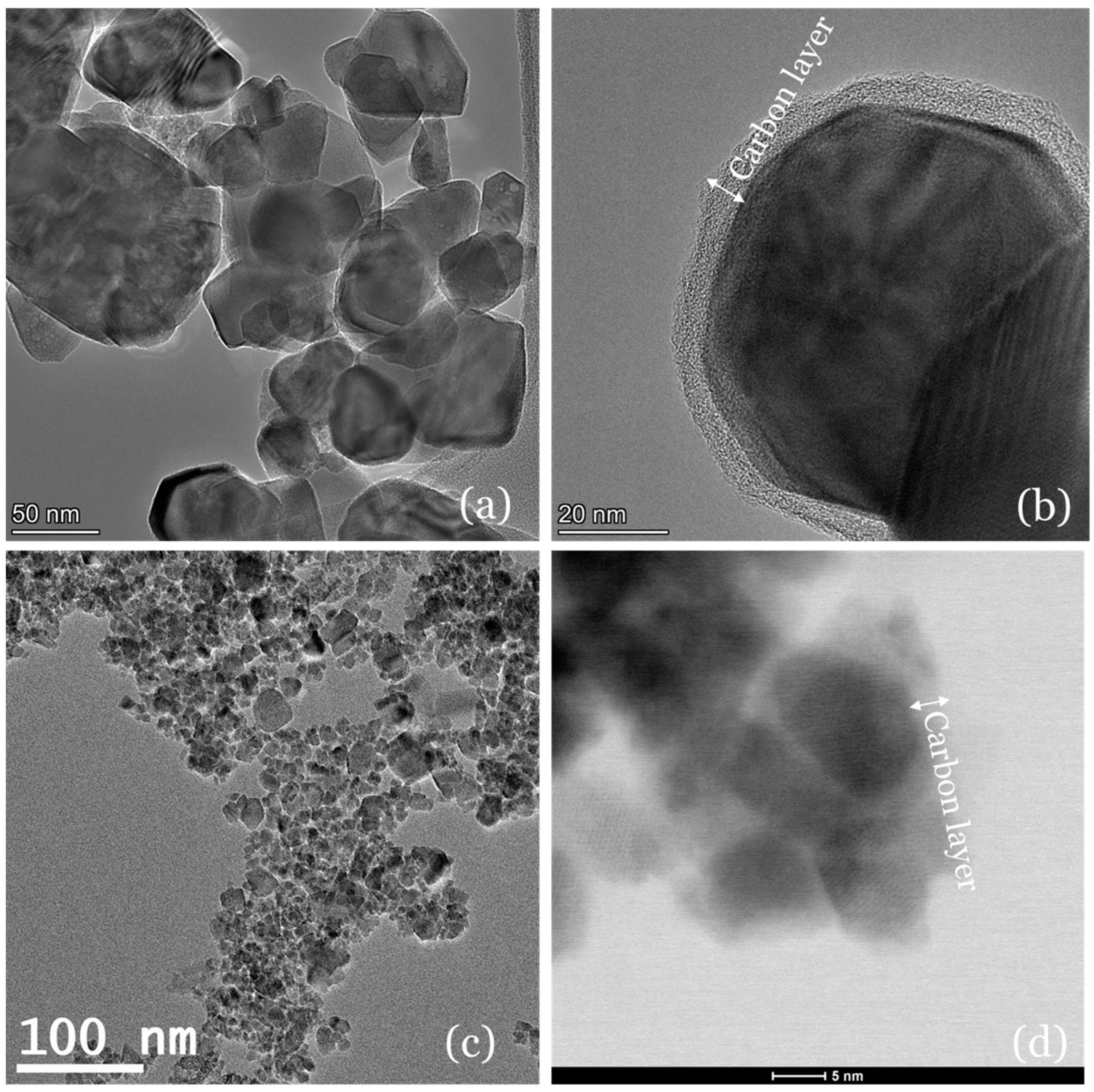
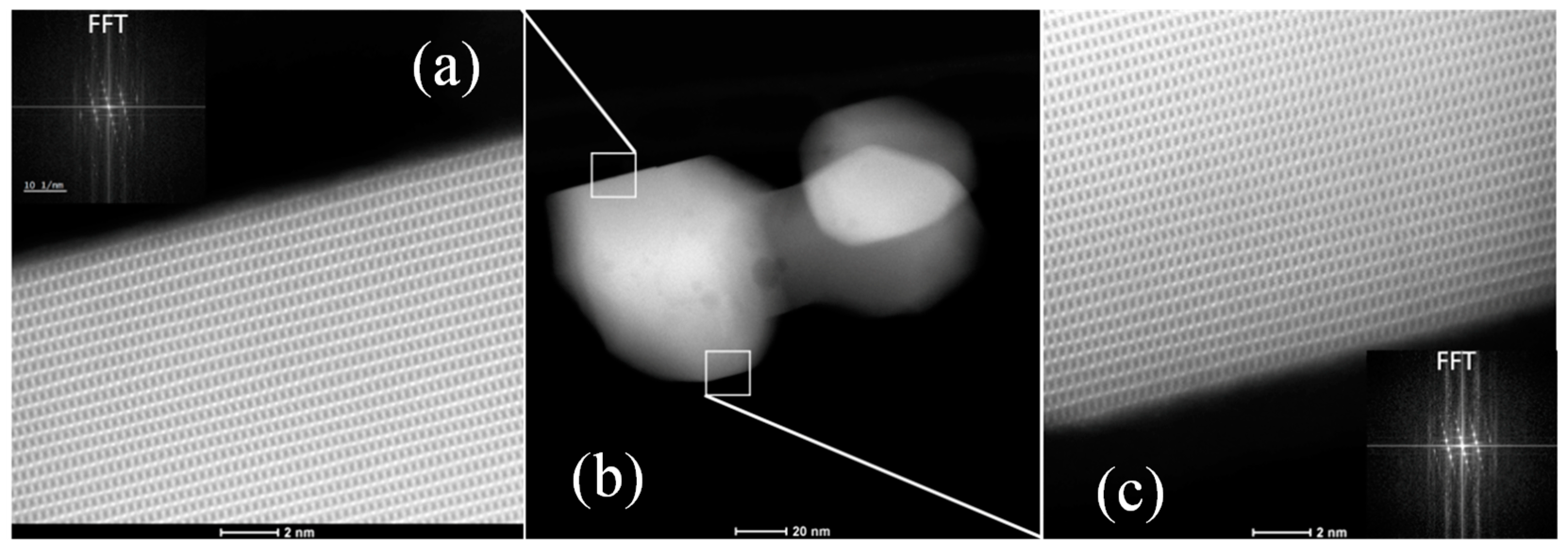
2.1. Morphology and Textural Properties

The transmission electron microscopy (TEM) images recorded for cores and carbon-coated materials are shown in Figure 1. The TEM images provide evidence of the successful synthesis of nanoparticles (NP), with average sizes of 45.5 ± 8.1 nm and 18.1 ± 3.4 nm, respectively, for cobalt ferrite, referred to as CoFe for simplification and Fe3O4. Reported values for CoFe typically range from 15 to 48 nm [24], synthesized by wet chemical methods, with other works reporting high average sizes from 100 to 200 nm [25] using sol–gel methods. The sizes of NPs can vary depending on the preparation method used, while Fe3O4 nanoparticles often range from 10 to 20 nm [26], aligning well with the values calculated from TEM observations, validated by the crystallite size model calculations obtained from X-ray diffraction (XRD) measurements (results presented and discussed later). CoFe tends to form larger particles due to higher crystallization temperatures and stronger magnetic interactions, which promote particle agglomeration and growth [27]. In the case of the CoFe sample synthesized in this study, the increased particle size can be attributed to the heat treatment used to remove impurities, which led to particle growth through sintering, also observed in the NPs of the work of Akter et al. [28].
Figure 1a,c show the size difference between the two cores, while Figure 1b,d confirm the formation of a thin layer of carbon resulting from the polymerization reaction of phloroglucinol–glyoxal acid. The carbon layer thickness obtained for CoFe was 6.6 ± 0.7 nm and for and 4.2 ± 0.2 nm for Fe3O4. Additionally, silica was not observed in the final nanoparticles, indicating that the etching process effectively removed the silica layer, as shown in energy-dispersive X-ray spectroscopy (EDS) images of CoFe@C in Figure S1.
Figure 2 presents high-angle annular dark-field scanning transmission electron microscopy (HAADF-STEM) images of CoFe nanoparticles, highlighting their crystalline nature. The central panel (Figure 2b) shows a lower magnification HAADF-STEM overview of a representative CoFe nanoparticle on a support film. The left (Figure 2a) and right panels (Figure 2c) are high-resolution HAADF-STEM images acquired from two different regions of the nanoparticle, as indicated by the white boxes. Both images reveal well-defined atomic lattice fringes across the entire imaged area, indicating high crystallinity.
Insets in the top-left and bottom-right corners (in Figure 2a and Figure 2c, respectively) show the corresponding Fast Fourier Transforms (FFTs) of each high-resolution image, displaying discrete and sharp diffraction spots. These FFT patterns further confirm the single-crystal nature of the nanoparticle, with no evidence of polycrystalline rings or multiple sets of spots indicative of twinning or grain boundaries.
The results of the N2 adsorption/desorption isotherms (shown in Figure S2) for the samples are summarized in Table 1. This table presents the specific surface area (SBET and SLangmuir), total pore volume (VT), and correlation coefficient (R2) for CoFe, CoFe@C, Fe3O4, and Fe3O4@C, highlighting the impact of carbon coating on their structural and porous properties.
Magnetite-based carbon materials exhibit significantly higher surface areas than cobalt ferrite-based materials, suggesting a more porous structure. This can be attributed to the smaller crystal size, as observed in TEM images and later confirmed by XRD results. The BET surface area of Fe3O4 increases from 83 to 120 m2 g−1 after carbon coating, a 44.6% increase, while CoFe shows a more pronounced 144.4% increase, from 9 to 22 m2 g−1. The Langmuir surface area follows the same trend, reinforcing the effect of carbon coating. In the study by Wojciechowska et al. [29], magnetite was synthesized with a surface area of 79 m2 g−1, which increased to 87 m2 g−1 after coating with glucose.
Regarding porosity, Fe3O4@C exhibits the highest total pore volume (0.34 cm3 g−1), which is over 15 times greater than Fe3O4 (0.022 cm3 g−1). CoFe@C also shows an increase in total pore volume (0.043 cm3 g−1) compared to CoFe (0.024 cm3 g−1), but the effect is less pronounced than in Fe3O4@C. The total pore volume can vary significantly depending on the synthesis method and conditions. One study [30] reported a total pore volume of 0.177 cm3 g−1 for carbon-coated cobalt ferrite nanoparticles. However, the lack of step-by-step characterization makes it difficult to determine the exact reasons for the higher pore volume observed. The high correlation coefficients (R2) confirm that the BET model reliably describes the materials’ surface properties, further validating the observed trends.
The BJH pore size distribution of the nanomaterials is shown in Figure S3. The results reveal limited mesoporosity, with average pore diameters ranging from 1 to 2.6 nm and only minor variations between coated and uncoated samples. However, the significant increase in surface area (SBET and Slangmuir) after carbon coating contrasts sharply with the nearly unchanged BJH pore sizes. This discrepancy suggests that the observed porosity primarily originates from intraparticle voids within nanoparticle aggregate, which is reasonable given these materials’ multi-core shell architecture, where micropores and interstitial space contribute more to surface area than resolvable mesopores.

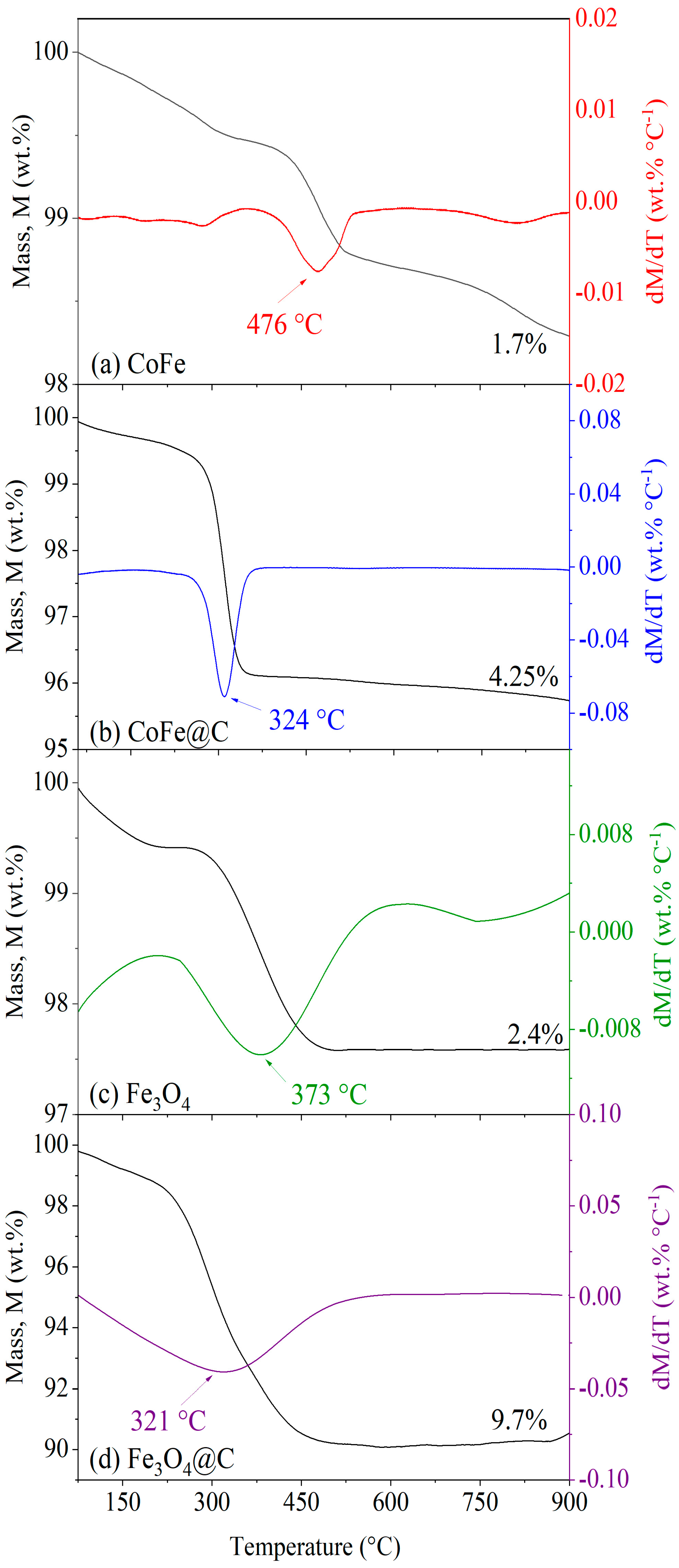
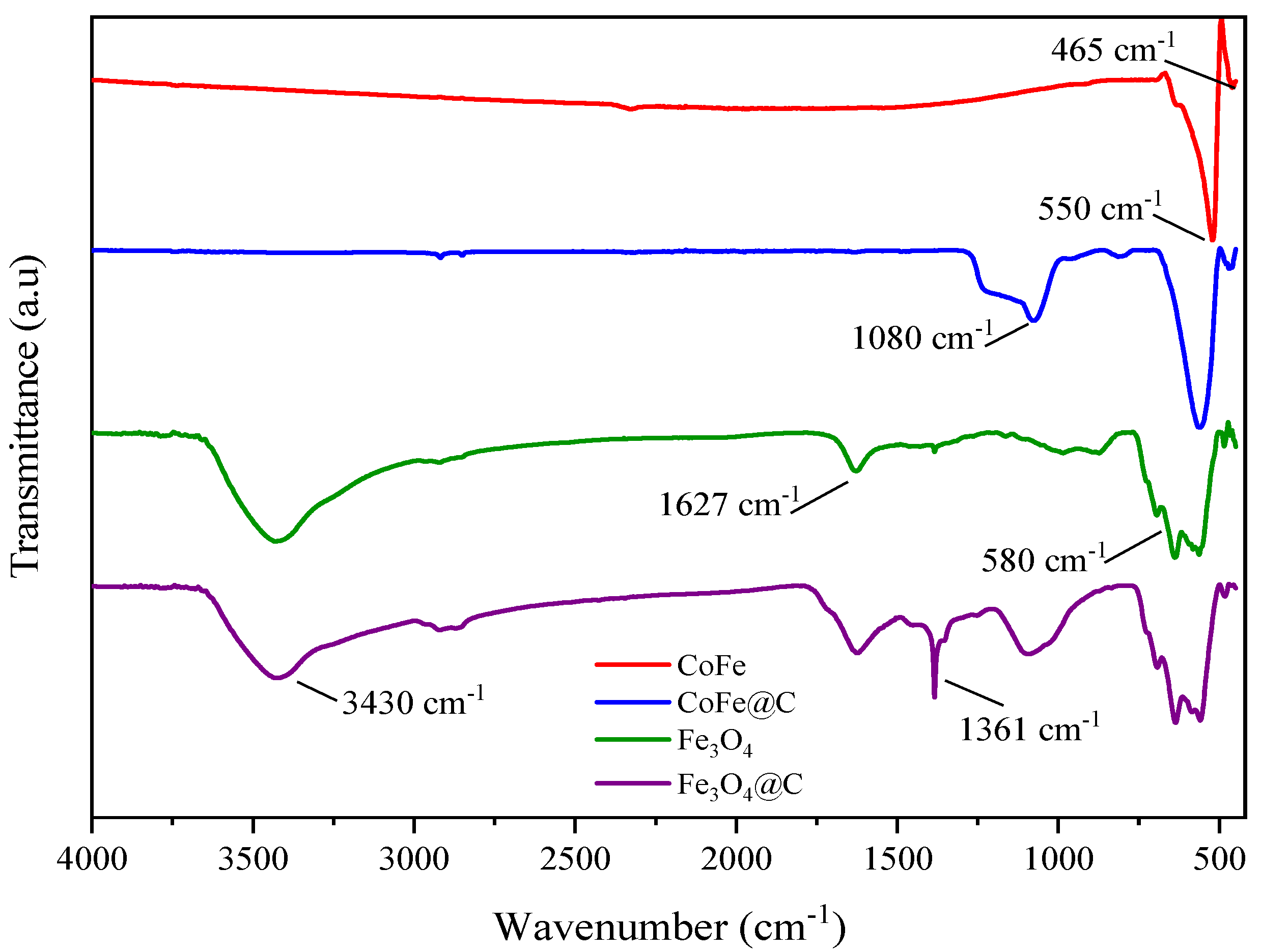
2.2. Thermal and Surface Properties

The results obtained for thermogravimetric analysis (TGA) of each nanomaterial and derivative thermogravimetry (DTG) under an air atmosphere are depicted in Figure 3. In Figure 3a,b, the low mass loss observed for the bare cores (CoFe and Fe3O4) indicates the high purity of the inorganic materials, with mass losses of approximately 1.7 and 2.4 wt.%, respectively. The high inorganic content of the samples aligns with the literature’s findings, in which CoFe was synthesized using a sol–gel method, which is known to produce well-crystallized metal oxides with minimal residual organics [31]. In the case of Fe3O4, the nanomaterial was obtained through SCS, a process that rapidly forms highly crystalline magnetite with minimal organic contamination due to its self-sustaining exothermic reaction [32]. These synthesis methods typically result in low mass loss in TGA, further supporting the high purity of the materials obtained in this study.
For the coated materials, as given in Figure 3b CoFe@C and Figure 3d Fe3O4@C, the formation of the carbon coating from phloroglucinol and glyoxal resin led to a mass loss of 4.25 and 9.7%, respectively, due to the combustion of organic groups. DTG analysis reveals temperature peaks around 320 °C for both materials, suggesting the decomposition of oxygen-containing functional groups in the carbon resin, such as hydroxyls (-OH), later identified in the Fourier-transform infrared spectroscopy (FT-IR) spectra. This thermal degradation is associated with the breakdown of the polymeric structure formed during the polymerization of phloroglucinol and glyoxal, leading to the release of volatile compounds and the progressive carbonization of the coating layer [12].
FT-IR spectra were used to identify chemical bonds, providing insight into the critical chemical modifications necessary to achieve the intended structure of the final nanoparticles. The results are displayed in Figure 4. The FT-IR spectra of CoFe and CoFe@C show bands between 465 and 550 cm−1, which are attributed to the stretching vibrations of the Co-O bond in octahedral sites [12]. A band around 550 cm−1 also corresponds to the Fe-O bond in tetrahedral sites [33]. These results confirm the presence of chemical bonds between cobalt oxides and iron oxides, indicating the formation of cobalt ferrite [12]. Furthermore, the peak near 1080 cm−1 corresponds to the stretching vibrations of C-OH. In the work of Gao et al. [33], the core cobalt ferrite was compared with carbon-coated NPs, obtained by a glucose method, and these findings suggest that the cobalt ferrite with carbon coating retains abundant amounts of functional groups formed.
The FTIR spectra of the magnetite core reveal characteristic peaks associated with the Fe-O stretching vibrations, with a prominent peak around 580 cm−1, corresponding to the Fe–O bond stretching in the octahedral sites of the magnetite structure [34]. Additionally, bands around 3430 and 1630 cm−1 suggest the presence of O-H stretching, likely from adsorbed water molecules or hydroxyl groups on the surface of the nanoparticles. In the FTIR spectra of Fe3O4@C, additional peaks appear, indicating the presence of functional groups within the carbon coating. A peak around 1361 cm−1 is attributed to C-H deformation vibrations in the plane [35], which reflects the incorporation of carbon-based functional groups into the coating. These changes highlight the modifications in surface chemistry due to the carbon coating.

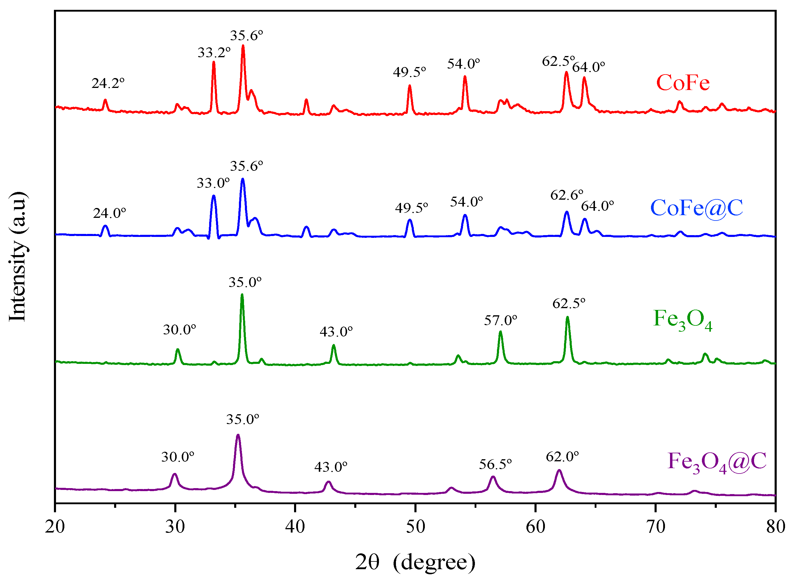
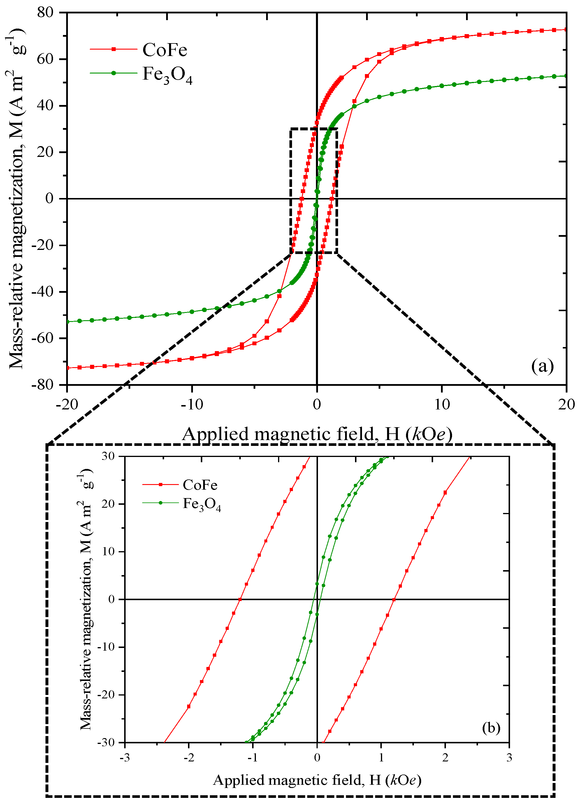
2.3. Crystalline Phase and Magnetic Properties

X-ray diffractograms of the core and coated samples are shown in Figure 5. The results obtained in this characterization were processed using HighScore Plus software (version 3.0.5) to confirm the materials’ composition. Data processed with the aid of HighScore Plus were also used to determine crystallite dimensions for the core.
The crystal structure of CoFe was confirmed to consist of 95% pure cobalt ferrite (CoFe2O4) and 5% hematite (Fe2O3), based on reference cards 96-153-3164 and 96-901-5965 from the Crystallography Open Database (COD), respectively. For pure magnetite (Fe3O4) nanomaterials, reference card 96-900-5842 from the COD was used. Similar diffractograms for core materials have been reported in another study [36].
Li et al. [37] found that while the coatings improved surface characteristics, they did not alter the fundamental crystalline composition of the coated materials. This suggests a consistent finding across various methodologies regarding the non-influence of carbon layers on crystal structures. Although the COD graphite reference card (90-115-77) was included in the analysis, the software failed to detect this carbon structure in the material, likely due to the low carbon content in the samples.
While XRD is a powerful technique to analyze nanoparticles, the semi-quantitative analysis of phase percentages and crystallite sizes in hybrid coated nanoparticles can be challenging. The complex nature of these multi-phase systems, potential peak overlaps, and the presence of amorphous components can affect the reliability of mathematical methods applied to XRD data [38]. Only the bare cores were analyzed. Two mathematical approaches (Halder–Wagner and Size–Strain Plot methods) were used to estimate crystal size. The crystallite sizes determined by these methods were 43 and 13.1 nm for CoFe and Fe3O4, respectively, using the Halder–Wagner method, and 56 and 10.6 nm using the Size–Strain Plot method, which is consistent with the values obtained from TEM analysis, yielding an average error of 5.8 and 18.7% for CoFe, and 27.6 and 58.5% for Fe3O4 in crystallite size determination using the Halder–Wagner and Size–Strain Plot methods, respectively.
Smaller crystals have a higher surface area-to-volume ratio, resulting in increased grain boundaries, as observed in their textural properties. In contrast, magnetite has a smaller crystal size, which indicates a larger surface area. This phenomenon enhances the surface area available for reactions or interactions, as noted on studies [38] on crystallization and material properties [39]. Additionally, these values are within the average range of those reported in recent literature [40,41], highlighting the effectiveness of the synthesis protocol in producing magnetite and cobalt ferrite nanoparticles with the desired crystallite size.
In this study, magnetic characterization was performed for the bare cobalt ferrite and magnetite samples to evaluate their magnetic properties, including saturation magnetization, coercivity, and remanence. In Figure 6, the results of the magnetic analysis of cobalt ferrite and magnetite cores recorded at 300 K are presented in terms of mass-relative magnetization (M) as a function of the applied magnetic field (H). Specifically, the cobalt ferrite and magnetite cores exhibit saturation magnetization of approximately ~72 and 52 A·m2·g−1, respectively; the presence of Co2+ ions in CoFe2O4 enhances exchange interactions but also introduces more localized magnetic moments, leading to a slightly higher saturation magnetization. This is consistent with various reports that indicate similar values for bulk and nanoparticle forms of cobalt ferrite [42] and magnetite [43].
Coercivity values were determined to be 1.1 kOe and 0.1 kOe for CoFe and Fe3O4, respectively. Research indicates that cobalt ferrite exhibits higher coercivity than magnetite, due to its strong magnetic anisotropy compared to magnetite [23]. Regarding remnant magnetization, cobalt ferrite shows a value of 30.5 A·m2·g−1, while magnetite exhibits A value of 3.5 A·m2·g−1. These values highlight the differences in magnetic behavior between the two materials, with cobalt ferrite exhibiting higher remanence after the external magnetic field is removed [44]. This can be attributed to the larger size of cobalt ferrite particles, which suggests a transition toward a more stable ferrimagnetic state. The measured values for the bare core and the hysteresis loop confirm the ferrimagnetic nature of the samples.
The use of magnetically recoverable catalysts, such as Fe3O4-based materials, allows for efficient catalyst recycling through simple magnetic separation, reducing operational costs and minimizing secondary pollution caused by metal leaching [45]. Moreover, magnetic materials enhance H2O2 activation by serving as redox mediators, accelerating the Fe2+/Fe3+ cycle and boosting the production of reactive oxygen species (ROS) such as hydroxyl radicals (HO), which play a crucial role in pollutant degradation [46]. Other studies [47] have also shown that magnetic materials are effective in activating peroxymonosulfate (PMS) for the degradation of various organic pollutants.

2.4. Single-Component CWPO Experiments

The concentration profiles of 2-NP, 4-NP, and H2O2 in the presence of each contaminant obtained in CWPO in single-component systems, using CoFe and Fe3O4 and the carbon-coated versions as catalysts, are shown in Figure 7.
All catalysts used demonstrated high catalytic activity in the decomposition of H2O2 (XH2O2 > 80%), as illustrated in Figure 7b,d, and in the removal of the pollutants 2-NP and 4-NP (Figure 7a,c), especially when compared to the non-catalytic (N.C) reaction, in which minimal decomposition of H2O2 was observed (XH2O2 in 2-NP = 12% and XH2O2 in 4-NP = 11%) after 8 h of reaction, which can be attributed to the thermal decomposition of H2O2 at the temperature of 80 °C at which the reaction was carried out [12], without sufficient generation of hydroxyl radicals (HO) for effective oxidation, resulting in insignificant conversion of the pollutants X2-NP = 8% and X4-NP = 15% during the experiments.
Among the catalysts, CoFe@C stood out as the most efficient in decomposing the pollutants, reaching around 50% conversion in the first 60 min for both pollutants and achieving the highest removal rate by eliminating approximately 90% of 2-NP and 96% of 4-NP in 8 h of reaction. Fe3O4@C showed similar performance, with removals of 86 and 94% for 2-NP and 4-NP, respectively, at the end of the experiment. These results are consistent with earlier research on iron-based nanocomposites. Notably, Hao et al. [48] demonstrated that Fe2O3@C nanoparticles achieved 80% Congo red removal within just 10 min, reaching 96.2% efficiency after 120 min of treatment.
On the other hand, the uncoated catalysts showed lower and slower degradation rates, especially for 2-NP, with conversions of 80% with CoFe and 70% with Fe3O4. For 4-NP, although degradation was slower than CoFe@C, at the end of the reaction, CoFe reached a conversion of 94%, while Fe3O4 converted 86% of the pollutant, close to the final conversion of Fe3O4@C.
Overall, it was observed that the degradation of 4-NP occurred faster than 2-NP. After 240 min of reaction, the conversion of 2-NP was between 47 and 68%, while the removal of 4-NP was significantly higher, ranging from 74 to 84%, depending on the catalyst. The higher adsorption rate of 4-NP by the catalysts, as shown in Figure 8, may justify this more efficient removal compared to 2-NP since the catalyst’s greater affinity for the pollutant favors its concentration near the active sites, where the generation of highly oxidizing species occurs [23]. Notably, the results presented in Figure 8 correspond to the adsorption of the catalysts without the addition of peroxide, further highlighting the role of adsorption in the removal process. In addition, the carbon-coated catalysts showed greater adsorption capacity for both pollutants compared to the uncoated materials (Fe3O4@C > CoFe@C > Fe3O4 > CoFe), reinforcing the importance of coating in optimizing the interaction between the pollutant and the catalyst’s active sites.
The superior performance of carbon-coated catalysts in adsorption is mainly due to the strengthening of adsorption interactions between the material and the pollutants caused by the carbonaceous phase, increasing the concentration of molecules near the active sites where the highly oxidizing hydroxyl radicals are generated [19,23]. However, adsorption is not the only determining factor for catalytic efficiency, as evidenced by the fact that Fe3O4@C adsorbs more pollutants than CoFe@C but has a lower removal rate in CWPO.
In addition to adsorption, CoFe materials show a strong synergy between cobalt and iron active sites, increasing the accessibility of Fe species and optimizing the binding of reaction intermediates. The presence of cobalt facilitates the reduction of Fe3+ to Fe2+, keeping the catalytic sites active, while metallic Co directly catalyzes the decomposition of H2O2 into hydroxyl radicals, increasing oxidation efficiency [49]. This interaction between the metals, combined with the presence of the carbonaceous coating, explains the superior performance of CoFe@C, which showed the highest removal rate among the catalysts, consolidating the following order of efficiency at the end of the reaction for both pollutants: CoFe@C > Fe3O4@C > CoFe > Fe3O4.
The carbonaceous coatings also improved the stability of the catalysts since iron leaching from the carbon-coated materials after 8 h of reaction was insignificant, as previously reported [19,49]. In contrast, CoFe showed leached iron concentrations of 5.3 and 5.5 mg/L in the single-component reactions to remove 2-NP and 4-NP, respectively, while Fe3O4 showed even higher values, reaching 12.8 and 13.1 mg/L for the same reactions, demonstrating that in addition to improving the catalytic activity of the materials, the coating also improved the durability of the materials.
Table S1 reports several works related to the application of carbon-coated metallic catalysts for the degradation of a range of contaminants [12,18,20,21,22,23,50,51]. The present work has the advantage of using a more benign carbon precursor compared to those reported using resorcinol–formaldehyde precursors [18,23,50]. Other works also reported safer carbon precursors (such as glucose), achieving comparable results (pollutant degradation in the range 80–98% in 80 min up to 48 h) as those reported in the present work. Only one other work reported a carbon-coated catalyst like ours for 4-NP degradation [23], achieving 80% conversion of 4-NP in 4 h of reaction (similar to our results). However, the carbon-coating was achieved using RF resin, and a much higher concentration of 4-NP was used.

2.5. Multi-Component CWPO Experiment

The concentration profiles of 2-NP, 4-NP, and H2O2 in the multi-component CWPO, where both pollutants were present simultaneously, are shown in Figure 9.
As observed in the single-component CWPO, the N.C reaction in the multi-component system also showed minimal decomposition of both H2O2 (XH2O2 = 10%) and the pollutants (X2-NP = 8% and X4-NP = 11%). Among the catalysts tested, CoFe@C stands out as the most efficient, decomposing 91% of H2O2 and achieving the highest contaminant degradation rates at the end of the reaction (96% of 2-NP and 99% of 4-NP), followed by Fe3O4@C (90% of 2-NP and 95% of 4-NP), CoFe (85% of 2-NP and 96% of 4-NP) and Fe3O4 (78% of 2-NP and 86% of 4-NP).
The total organic carbon (TOC) was also measured after each reaction. Table S2 shows a proportional decrease—lower in percentage than the degradation—but still confirms effective mineralization rather than just molecular transformation. In the work of Khan [51], the synthesized nanocomposite catalysts also showed excellent catalytic activity for nitrophenol reduction. Notably, Cu0@Alg-OrP-BDs achieved 98% efficiency in 4-NP reduction with a rate of 1.568 min−1.
Pollutant degradation and peroxide decomposition were slightly higher in the multi-component system compared to the single-component system, because in multi-component systems, the increased molecular population of pollutants and oxidants enhances the probability of collisions with catalyst surfaces. This leads to more frequent adsorption events, resulting in higher overall reaction rates compared to single-component systems, where the availability of reactive molecules is more limited [52]. Adsorption of the pollutants was very similar in both systems, as shown in Figure 8, suggesting that both interact with similar active sites, which may limit their retention on the surface. Even so, 4-NP was more adsorbed by the catalysts than 2-NP, which influenced the lower degradation of 2-NP throughout the process, as observed in other studies with other magnetic catalysts [51,53].
However, the high catalytic activity of the materials compensates for this reduction in adsorption, allowing for efficient degradation of the pollutants. The decomposition of H2O2 (as shown in Figure 9c) supports this behavior, since CoFe@C sustained the highest rate of H2O2 consumption, ensuring a continuous supply of hydroxyl radicals and maintaining its catalytic efficiency even in a more complex system. Although Fe3O4@C showed the highest adsorption values, the superior performance of CoFe@C reinforces that CWPO efficiency depends not only on surface affinity with pollutants but also on the catalyst’s ability to decompose H2O2 and generate highly oxidizing hydroxyl radicals.
Additionally, as in the single-component CWPO, no leaching of iron was detected in the coated catalysts, while the uncoated materials showed leached iron concentrations close to those found in the single-component system (CoFe: 5.66 mg/L and Fe3O4: 12.mg/L) at the end of the reaction. In a previous study carried out by the group [12], the CoFe@C catalyst showed no significant loss of efficiency for three cycles of utilization.
Moreover, in Figure S4, the best catalysts (CoFe@C) recovered at the end of the reaction maintained their magnetic response without significant loss of magnetism. This confirms the following: (1) the magnetic core did not undergo degradation or phase transformation (which would show loss of magnetic property), and (2) the carbon coating effectively protected the material against corrosion or destabilization. In single- and multi-component experiments, all catalysts were also recovered with a strong neodymium magnet. The recovery rate was ca. 90% for all materials, which was expected considering the magnetic nature of the catalysts and is aligned with previous reports [18].

3. Materials and Methods

3.1. Reagents and Materials

The reagents utilized in this study were used as received, without further purification, and ultrapure water was employed in all solutions. To prepare the magnetic cores, iron (III) nitrate hexahydrate (99 wt.%, Aldrich, St. Louis, MO, USA), cobalt (II) chloride hexahydrate (99 wt.%, Fischer, Ried im Innkreis, Austria), citric acid monohydrate (99%, WWR, Centennial, CO, USA), ethanol (99.8% v/v, Fischer, Ried im Innkreis, Austria), and ethanediol (99% v/v, Fischer, Ried im Innkreis, Austria) were used. The multi-core shell architecture was synthesized using phloroglucinol dihydrate (98 wt.%, Alfa Aesar, Haverhill, MA, USA), Pluronic® F-127 (Sigma Aldrich, St. Louis, MO, USA), tetraethyl orthosilicate (98% v/v, Fluka Chemika, Buchs, Switzerland), sodium hydroxide (98%, Labkem, Lucknow, India), ammonia solution (28–30% v/v, Merck, Darmstadt, Germany), and glyoxal solution (40 wt.%, Alfa Aesar, Haverhill, MA, USA). For CWPO experiments and analytical techniques, 2-NP (98 wt.%, Sigma-Aldrich), 4-NP (98 wt.%, Sigma-Aldrich, St. Louis, MO, USA), hydrogen peroxide (30% w/v, Fischer Chemical, Ried im Innkreis, Austria), titanium (IV) oxysulfate (99.99% w/v, Sigma Aldrich, St. Louis, MO, USA), sulfuric acid (98% v/v, Labkem), sodium sulfite (98 wt.%, Panreac, Castellar del Vallès, Spain), acetonitrile (99.9% v/v, Fisher Scientific, Hampton, NH, USA), and orthophosphoric acid (85% v/v, Fisher Chemical, Ried im Innkreis, Austria) were employed.

3.2. Synthesis of Magnetic Cores

The development of the targeted multi-core shell architecture was carried out through a systematic, four-phase approach: (a) fabrication of the magnetic core, (b) application of a resin coating, (c) thermal treatment, and (d) etching. Each phase was carefully designed to ensure structural integrity and functionality.
Two different methodologies were used for the first step in obtaining each magnetic core. The magnetic cobalt ferrite core was synthesized according to a sol–gel methodology as previously described [54]. In the sol–gel methodology, the metal precursor initially undergoes hydrolysis to produce a metal hydroxide solution (resulting in a sol). Condensation of the solution results in a gel structure. The excess moisture in the gel is removed, and the resultant solid is calcined to remove organic impurities. For a more detailed description of the methodology, please refer to the supplementary information (SI) provided by Silva et al. [12].
The synthesis of superparamagnetic magnetite was achieved by SCS, as described elsewhere [55]. Briefly, a 12 mM citric acid solution (10 mL) was slowly added (1 mL min−1) using a peristaltic pump to 10 mL of an iron(III) nitrate solution (21 mM). The solution was heated at 80 °C in a drying oven for 6.5 h. To maintain an oxygen-free environment, the reaction flask was placed in an oil bath on a magnetic stirrer under a continuous nitrogen flow (100 N cm3 min−1) at room temperature for one hour. After N2 circulation, the solution was heated at 180 °C for 3 h. The resulting product was purified by repeated washing with distilled water until neutral pH was achieved, followed by a five-minute centrifugation at 6000 rpm (MPW-260R centrifuge, MPW Med. Instruments, Warsaw, Poland). The material was dried overnight in an air oven at 60 °C.

3.3. Carbon Coating

The coating procedure considered in this work is a phloroglucinol and glyoxal resin, which allows for the development of a thin carbon coating that is significantly more sustainable when compared to the more traditional formaldehyde and resorcinol resin formulation.
In brief, a suspension containing 0.25 g of the core in 50 mL of distilled water is prepared with the aid of an ultrasonic bath. The suspension is transferred to a round bottom flask that contains 0.12 mL of ammonia reagent, 0.1 g of phloroglucinol, and Pluronic® F-127 (Sigma Aldrich, St. Louis, MO, USA), which acts as a soft template to direct the self-assembly of precursors and enhance the porosity of the thin carbon layer [56]. During the annealing step, Pluronic® F-127 is removed, leaving behind a well-defined porous structure [57]. This mixture is stirred (30 °C, 1 h) to ensure proper dispersion of reactants. Then, 0.21 mL of TEOS and 0.15 mL of glyoxal are added to start the condensation reaction of TEOS and the polymerization reaction of phloroglucinol–glyoxal acid [12].
After initiating the reaction, the temperature and stirring rate are maintained constant for 6 h. Upon increasing the temperature to 80 °C, the mixture is held at this level for an additional 8 h. Once the reaction is complete, the resulting solid product is separated from the mixture and repeatedly washed with distilled water until the washings reach a neutral pH. Magnetic nanoparticles are efficiently recovered during the washing process using a neodymium magnet, which attracts and isolates them from the liquid medium. The selection of reactants was guided by prior studies demonstrating the feasibility of carbonizing phloroglucinol/glyoxalic acid-based resin [12].
The recovered nanomaterials were dried, followed by annealing in an inert atmosphere in a tubular furnace (ROS 50/250/12, Thermoconcept, Mérignac, France) with a heating ramp of 120 °C h−1 for 450 min until it reached 600 °C.
In the final step, the carbon-coated nanoparticles were subjected to an etching treatment by agitating them in a 10 M sodium hydroxide (NaOH) solution for 16 h at room temperature to eliminate silica residues. The purified nanoparticles were then thoroughly rinsed with distilled water until a neutral pH was achieved in the wash solution. The resulting products were designated as CoFe@C and Fe3O4@C for further characterization.

3.4. Characterization Techniques

TEM examined the nanoparticle’s morphology (multi-core shell architecture and size). Bright-field TEM images were taken with a JEOL JEM 2100 (JEOL, Tokyo, Japan), operating at 200 kV. For the determination of textural properties of the bare core and of the coated samples, the samples were initially degasified (120 °C, 16 h). The N2 adsorption–desorption isotherms were obtained at 77 K in a NOVATOUCH LX4 adsorption analyzer (Quantachrome Instruments, Boynton Beach, FL, USA) provided by Quantachrome. Total pore volume (VT), BET, and Langmuir-specific surface areas (SBET and SLangmuir) were estimated using the Quantachrome TouchWinTM software (version 1.21). Pore size distributions were determined using the Barrett–Joyner–Halenda (BJH) method applied to the desorption branch of the N2 isotherms.
TGA (SDT650, TA Instruments, New Castle, DE, USA) was performed for all samples in an air atmosphere from 50 to 950 °C (heating rate of 10 °C min−1) to evaluate the mass loss of the samples during the synthesis procedure. DTG was calculated for all samples based on the derivative of the mass loss result concerning time. The DTG results allowed the analysis of the presence/absence of specific groups during the synthesis steps.
The functionalities present in the samples were studied throughout the synthesis procedure using FT-IR (FT-IR spectrophotometer UATR Two, Perkin Elmer, Waltham, MA, USA), with a resolution of 4 cm−1 and scan range 2500–400 cm−1. Pellets of the samples were prepared by mixing ca. 1 mg of the sample with ca. 100 mg of KBr, and then pressing the mixture into a mold under 8 tons of pressure for 3 min.
The XRD technique characterized the magnetic core and the final nanoparticles obtained in both methodologies to perform crystalline phase identification. A PANalytical X’Pert Pro diffractometer equipped with an X’Celerator detector and secondary monochromator (PANalytical B.V., Almelo, The Netherlands) in θ/2θ Bragg–Brentano geometry carried out the analyses at room temperature. The measurements were carried out using 40 kV and 30 mA, CuKα radiation (λα1 =1.54060 Å and λα2 = 1.54443 Å), 0.017°/step, 100 s/step, in a 10–80° 2θ angular range. Data processing was performed using the software X’Pert HighScore Plus (version 3.0.5) with reference cards from the Crystallography Open Database. The XRD pattern obtained for the bare core was further used to determine crystallite size by using the Halder–Wagner and Size–Strain Plot method. Coercivity, magnetic remanence, and magnetic saturation were determined upon analysis of M-H curves obtained by a SQUID-VSM (Quantum Design, San Diego, CA, USA) magnetometer for the bare cores.

3.5. Liquid-Phase Oxidation Runs and Analytical Techniques

CWPO runs were conducted in a two-necked round bottom flask of 250 mL using 100 mL of 2-NP and 4-NP solutions with a concentration of 50 mg/L (for single-component systems) and pH 3.5 adjusted by the addition of H2SO4 aqueous solution (0.5 M). In multi-component systems, the initial concentration of each pollutant was also 50 mg L−1 to understand the impact on the catalytic efficiency upon increased competition for active sites. Then, the resulting solution was submerged into an oil bath and coupled to a condenser and a magnetic stirring plate. The mixture was agitated with a magnetic stirrer for 5 min to ensure thermal stability at 80 °C, corresponding to the temperature used in the oxidation tests for removal of 2-NP and 4-NP. After thermal stability, the stoichiometric quantity of H2O2 for the complete oxidation of 2-NP and 4-NP was dosed ([H2O2]0 = 513 mg L−1). Then, 0.25 g of catalyst was loaded into the system ([catalyst] = 2.5 g L−1). The time of addition of the catalyst represents the initial moment of the reaction (t0 = 0 min). During the experiment, three 1 mL samples were collected from the reaction medium at 0, 5, 15, 30, 60, 120, 240, 360, and 480 min. Those samples were stored in Eppendorf vials in the presence of Na2SO3 for the complete decomposition of H2O2. After the CWPO reactions, the catalyst was recovered with a strong magnet, washed with distilled water, and dried in oven at 60 °C for 24 h. Additionally, under the same operating conditions, adsorption tests and blank CWPO runs were performed in the absence of H2O2 and catalyst.
During the catalytic experiments, 1 mL aliquots were collected at regular intervals from the reaction vessel for quantitative analysis of 2-nitrophenol (2-NP) and 4-nitrophenol (4-NP) concentrations. These determinations were performed using high-performance liquid chromatography (HPLC) following a modified version of the method reported in reference [11]. The HPLC system (Jasco, Oklahoma City, OK, USA) incorporated the following components: a UV/Vis detector (model UV-2075 Plus,), a quaternary gradient pump (PU-2089 Plus) maintaining a solvent flow rate of 1 mL min−1, and a BiPhenyl column (BPH 5 µm 150 × 2.1 mm; 5 μm particle size). The isocratic elution program employed a mobile phase composed of two solvents, (A) acetonitrile, and (B) ultrapure water with 0.1% H3PO4, mixed in a 40:60 ratio. The optimal detection wavelength for 2-NP (277 nm) was established through prior UV–Vis spectroscopic analysis (Jasco V530 spectrophotometer, Jasco, Oklahoma City, OK, USA).
For iron leaching assessment, the post-reaction solutions from the catalytic wet peroxide oxidation (CWPO) trials were first filtered through a 0.45 μm membrane. The dissolved iron content in the filtrate was then quantified by flame atomic absorption spectrometry using a Varian Spectra 220 spectrometer (Varian, Palo Alto, CA, USA). The total organic carbon (TOC) was also determined at the end of the CWPO runs using a Shimadzu TOC-5000A analyzer (Shimadzu, Tokyo, Japan).

4. Conclusions

The findings of this study demonstrate the successful synthesis of hybrid multi-core magnetic catalysts with cobalt ferrite and magnetite cores, prepared via sol–gel and SCS methods, respectively. Incorporating a novel, less hazardous phloroglucinol–glyoxal-derived resin as a coating effectively enhanced the stability and catalytic performance of the materials. Comprehensive characterization confirmed the formation of a well-defined core–shell structure, providing valuable insights into particle size, crystallinity, textural properties, and magnetic behavior.
The findings of this study confirm that carbon-coated catalysts outperformed their uncoated counterparts in CWPO. In the single-component system, CoFe@C achieved 90% degradation of 2-NP and 96% of 4-NP within 8 h, while Fe3O4@C exhibited similar efficiency, with removal rates of 86% for 2-NP and 94% for 4-NP. In the multi-component system, CoFe@C demonstrated the highest catalytic activity, decomposing 91% of H2O2 and achieving 96% removal of 2-NP and 99% of 4-NP, followed by Fe3O4@C with slightly lower degradation rates. Moreover, iron leaching was observed in the uncoated catalysts, whereas the carbon-coated materials exhibited high structural stability with negligible metal loss. Additionally, the coated catalysts demonstrated superior adsorption capacity, enhancing their overall pollutant removal efficiency.
The synthesized hybrid magnetic catalysts present a promising approach for pollutant degradation, offering both high catalytic efficiency and facile recovery due to their magnetic properties. Their dual-function mechanism—combining the catalytic activity of the hybrid core with an environmentally friendly and stabilizing coating—positions them as effective candidates for sustainable environmental remediation. Future research should focus on optimizing the porosity of the carbon shell and further evaluating the long-term performance and biological interactions of these materials in real-world applications.

Supplementary Materials

The following supporting information can be downloaded at: https://www.mdpi.com/article/10.3390/catal15040376/s1. The supplementary materials contains the following information: Figure S1. (a) HAADF-STEM image, (b) Energy-Dispersive X-Ray Spectroscopy (EDS) elemental mapping, and (c) elemental mapping per element of the CoFe@C sample. Image reproduced from supplementary material published in a previous work [12]; Figure S2. N2 adsorption-desorption isotherms obtained at 77k for (a) CoFe, (b) Fe3O4, (c) CoFe@C, and (d) Fe3O4@C; Table S1. Carbon-coated metallic particles applied for the degradation of several pollutants; Figure S3: BJH pore size distribution for (a) CoFe, (b) CoFe@C, (c) Fe3O4, and (d) Fe3O4@C; Figure S4: Catalysts recovered (CoFe@C) in the end of the reaction: (a) Without the presence of a magnetic field and (b) In the presence of a magnetic field; Table S2. Total organic carbon (TOC) reduction after single and multicomponent reactions

Author Contributions

A.P.B.: Writing—original draft, Conceptualization, Investigation, Formal analysis, Visualization. A.J.B.B.: Writing—original draft, Investigation, Formal analysis. A.S.S.: Writing—review and editing, Investigation, Formal analysis, Methodology, Visualization. A.P.F.: Writing—review and editing, Investigation. F.F.R.: Writing—original draft, Investigation. I.Ç.: Formal analysis, Writing—review and editing, Investigation. M.B.-L.: Writing—review and editing, Investigation. F.L.D.: Writing—review and editing, Investigation. H.T.G.: Writing—review and editing, Funding acquisition, Supervision Project administration. All authors have read and agreed to the published version of the manuscript.

Funding

This work was financially supported by national funds through FCT/MCTES (PIDDAC): CIMO, UIDB/00690/2020 (DOI: 10.54499/UIDB/00690/2020) and UIDP/00690/2020 (DOI: 10.54499/UIDP/00690/2020); SusTEC, LA/P/0007/2020 (DOI: 10.54499/LA/P/0007/2020). Also supported by national funds through FCT/MCTES (PIDDAC). Fernanda F. Roman acknowledges the national funding by FCT and the European Social Fund, FSE, through the individual research grant SFRH/BD/143224/2019. Adriano S. Silva was supported by the doctoral Grant SFRH/BD/151346/2021 and Ana Paula Ferreira by PRT/BD/153090/2021, financed by FCT with funds from NORTE2020, under the MIT Portugal Program. The authors are also grateful for the financial support provided by Fundação La Caixa for the project INOVÁGUA.

Data Availability Statement

The original contributions presented in this study are included in the article/Supplementary Material. Further inquiries can be directed to the corresponding authors.

Conflicts of Interest

The authors declare no conflicts of interest.

References

  1. He, C.; Liu, Z.; Wu, J.; Pan, X.; Fang, Z.; Li, J.; Bryan, B.A. Future Global Urban Water Scarcity and Potential Solutions. Nat. Commun. 2021, 12, 4667. [Google Scholar] [CrossRef] [PubMed]
  2. Silva, A.S.; Filho, P.Z.; Ferreira, A.P.; Roman, F.F.; Baldo, A.P.; Rauhauser, M.; Diaz de Tuesta, J.L.; Pereira, A.I.; Silva, A.M.T.; Pietrobelli, J.M.T.; et al. Occurrence of Micropollutants in Surface Water and Removal by Catalytic Wet Peroxide Oxidation Enhanced Filtration Using Polymeric Membranes Loaded with Carbon Nanotubes. Chem. Eng. J. Adv. 2025, 21, 100707. [Google Scholar] [CrossRef]
  3. Xiong, Z.; Zhang, H.; Zhang, W.; Lai, B.; Yao, G. Removal of Nitrophenols and Their Derivatives by Chemical Redox: A Review. Chem. Eng. J. 2019, 359, 13–31. [Google Scholar] [CrossRef]
  4. Ji, Y.; Shi, Y.; Yang, Y.; Yang, P.; Wang, L.; Lu, J.; Li, J.; Zhou, L.; Ferronato, C.; Chovelon, J.-M. Rethinking Sulfate Radical-Based Oxidation of Nitrophenols: Formation of Toxic Polynitrophenols, Nitrated Biphenyls and Diphenyl Ethers. J. Hazard. Mater. 2019, 361, 152–161. [Google Scholar] [CrossRef]
  5. Kavitha, V.; Palanivelu, K. Degradation of Nitrophenols by Fenton and Photo-Fenton Processes. J. Photochem. Photobiol. A Chem. 2005, 170, 83–95. [Google Scholar] [CrossRef]
  6. Priyanka, M.; Saravanakumar, M.P. New Insights on Aging Mechanism of Microplastics Using PARAFAC Analysis: Impact on 4-Nitrophenol Removal via Statistical Physics Interpretation. Sci. Total Environ. 2022, 807, 150819. [Google Scholar] [CrossRef]
  7. ToxFAQs TM for Nitrophenols. 1995. Available online: https://wwwn.cdc.gov/TSp/ToxFAQs/ToxFAQsDetails.aspx?faqid=879&toxid=172 (accessed on 9 April 2025).
  8. Chaara, D.; Pavlovic, I.; Bruna, F.; Ulibarri, M.A.; Draoui, K.; Barriga, C. Removal of Nitrophenol Pesticides from Aqueous Solutions by Layered Double Hydroxides and Their Calcined Products. Appl. Clay Sci. 2010, 50, 292–298. [Google Scholar] [CrossRef]
  9. Asif, M.; Deng, L.; Mao, Y.; Khan, H.U.; Tang, Q. Efficient Degradation of 2-Nitrophenol during the UV/Chlorine Treatment in the Presence of Fe(III): Kinetics, DFT Calculation and HNMs Formation. J. Environ. Chem. Eng. 2025, 13, 115712. [Google Scholar] [CrossRef]
  10. Diaz De Tuesta, J.L.; Pantuzza, G.F.; Silva, A.M.T.; Praça, P.; Faria, J.L.; Gomes, H.T. Catalysts Prepared with Matured Compost Derived from Mechanical-Biological Treatment Plants for the Wet Peroxide Oxidation of Pollutants with Different Lipophilicity. Catalysts 2020, 10, 1243. [Google Scholar] [CrossRef]
  11. Ribeiro, R.S.; Silva, A.M.T.; Figueiredo, J.L.; Faria, J.L.; Gomes, H.T. Removal of 2-Nitrophenol by Catalytic Wet Peroxide Oxidation Using Carbon Materials with Different Morphological and Chemical Properties. Appl. Catal. B 2013, 140–141, 356–362. [Google Scholar] [CrossRef]
  12. Silva, A.S.; Roman, F.F.; Dias, A.V.; Diaz de Tuesta, J.L.; Narcizo, A.; da Silva, A.P.F.; Çaha, I.; Deepak, F.L.; Bañobre-López, M.; Ferrari, A.M.C.; et al. Hybrid Multi-Core Shell Magnetic Nanoparticles for Wet Peroxide Oxidation of Paracetamol: Application in Synthetic and Real Matrices. J. Environ. Chem. Eng. 2023, 11, 110806. [Google Scholar] [CrossRef]
  13. Kalmakhanova, M.S.; Diaz de Tuesta, J.L.; Malakar, A.; Gomes, H.T.; Snow, D.D. Wastewater Treatment in Central Asia: Treatment Alternatives for Safe Water Reuse. Sustainability 2023, 15, 14949. [Google Scholar] [CrossRef]
  14. Roman, F.F.; Silva, A.S.; Diaz de Tuesta, J.L.; Baldo, A.P.; Lopes, J.P.M.; Gonçalves, G.; Pereira, A.I.; Praça, P.; Silva, A.M.T.; Faria, J.L.; et al. Plastic Waste-Derived Carbon Nanotubes: Influence of Growth Catalyst and Catalytic Activity in CWPO. J. Environ. Chem. Eng. 2025, 13, 115206. [Google Scholar] [CrossRef]
  15. Kim, T.Y.; Jo, S.; Lee, Y.; Kang, S.H.; Kim, J.W.; Lee, S.C.; Kim, J.C. Influence of Ni on Fe and Co-Fe Based Catalysts for High-Calorific Synthetic Natural Gas. Catalysts 2021, 11, 697. [Google Scholar] [CrossRef]
  16. Rocha, R.P.; Pereira, M.F.R.; Figueiredo, J.L. Metal-Free Carbon Materials as Catalysts for Wet Air Oxidation. Catal. Today 2020, 356, 189–196. [Google Scholar] [CrossRef]
  17. Anjaneyulu, B.; Rana, R.; Versha; Afshari, M.; Carabineiro, S.A.C. The Use of Magnetic Porous Carbon Nanocomposites for the Elimination of Organic Pollutants from Wastewater. Surfaces 2024, 7, 120–142. [Google Scholar] [CrossRef]
  18. Guari, N.M.C.; Silva, A.S.; Diaz de Tuesta, J.-L.; Pottker, W.E.; Cordeiro, P.Y.; Gomes, H.T. Magnetic CoFe2O4@carbon Yolk-Shell Nanoparticles as Catalysts for the Catalytic Wet Peroxide Oxidation of Paracetamol: Kinetic Insights. Glob. NEST J. 2023, 25, 57–66. [Google Scholar] [CrossRef]
  19. Ribeiro, R.S.; Silva, A.M.T.; Tavares, P.B.; Figueiredo, J.L.; Faria, J.L.; Gomes, H.T. Hybrid Magnetic Graphitic Nanocomposites for Catalytic Wet Peroxide Oxidation Applications. Catal. Today 2017, 280, 184–191. [Google Scholar] [CrossRef]
  20. Li, X.; Wang, J.; Zhang, X.; Hou, X.; Xu, H.; Yao, Z.; Jiang, Z. A High-Efficient Carbon-Coated Iron-Based Fenton-Like Catalyst with Enhanced Cycle Stability and Regenerative Performance. Catalysts 2020, 10, 1486. [Google Scholar] [CrossRef]
  21. Mo, Y.; Che, C.; Han, W.; Chen, F.; Guan, J.; Zhang, F.; Yang, B.; Ren, X.; Li, H.; Ahmed, S.; et al. Fabrication of Carbon-Coated Iron-Based Porous Heterogeneous Fenton Catalyst and Enhanced Degradation Performance towards Ciprofloxacin. Chem. Eng. J. 2024, 497, 154680. [Google Scholar] [CrossRef]
  22. Gao, Y.; Yang, B.; Yang, Y.; Ming, H.; Liu, G.; Zhang, J.; Hou, Y. Carbon-Coated ZnFe2O4 Nanoparticles as an Efficient, Robust and Recyclable Catalyst for Photocatalytic Ozonation of Organic Pollutants. J. Environ. Chem. Eng. 2022, 10, 107419. [Google Scholar] [CrossRef]
  23. Ribeiro, R.S.; Gallo, J.; Bañobre-López, M.; Silva, A.M.T.; Faria, J.L.; Gomes, H.T. Enhanced Performance of Cobalt Ferrite Encapsulated in Graphitic Shell by Means of AC Magnetically Activated Catalytic Wet Peroxide Oxidation of 4-Nitrophenol. Chem. Eng. J. 2018, 376, 120012. [Google Scholar] [CrossRef]
  24. Maaz, K.; Mumtaz, A.; Hasanain, S.K.; Ceylan, A. Synthesis and Magnetic Properties of Cobalt Ferrite (CoFe2O4) Nanoparticles Prepared by Wet Chemical Route. J. Magn. Magn. Mater. 2007, 308, 289–295. [Google Scholar] [CrossRef]
  25. Saragi, T.; Nurjannah, S.; Novia, R.; Syakir, N.; Simanjuntak, E.; Safriani, L.; Risdiana; Bahtiar, A. Synthesis of Cobalt Ferrite Particles by Utilized Sol-Gel Method. In Materials Science Forum; Trans Tech Publications Ltd.: Wollerau, Switzerland, 2015; Volume 827, pp. 219–222. [Google Scholar]
  26. Nguyen, M.D.; Tran, H.V.; Xu, S.; Lee, T.R. Fe3O4 Nanoparticles: Structures, Synthesis, Magnetic Properties, Surface Functionalization, and Emerging Applications. Appl. Sci. 2021, 11, 11301. [Google Scholar] [CrossRef]
  27. Abbas, M.; Parvatheeswara Rao, B.; Nazrul Islam, M.; Kim, K.W.; Naga, S.M.; Takahashi, M.; Kim, C. Size-Controlled High Magnetization CoFe2O4 Nanospheres and Nanocubes Using Rapid One-Pot Sonochemical Technique. Ceram. Int. 2014, 40, 3269–3276. [Google Scholar] [CrossRef]
  28. Akter, S.; Khan, M.N.I.; Ferdous, F.; Das, H.N.; Alam, M.K.; Rahman, M.A.; Hasan, T.; Syed, I.M. Unveiling the Role of Sintering Temperatures in the Physical Properties of Cu-Mg Ferrite Nanoparticles for Photocatalytic Application. Heliyon 2024, 10, e40771. [Google Scholar] [CrossRef]
  29. Wojciechowska, A.; Lendzion-Bielun, Z. Synthesis and Characterization of Magnetic Nanomaterials with Adsorptive Properties of Arsenic Ions. Molecules 2020, 25, 4117. [Google Scholar] [CrossRef]
  30. Denisova, K.; Ilyin, A.A.; Rumyantsev, R.; Sakharova, J.; Ilyin, A.P.; Gordina, N. Low-Temperature Synthesis and Catalytic Activity of Cobalt Ferrite in Nitrous Oxide (N2O) Decomposition Reaction. Catalysts 2021, 11, 889. [Google Scholar] [CrossRef]
  31. Raut, S.D.; Dahotre, S.G.; Singh, L.N.; Jadhav, S.N. Synthesis and Characterization of Magnetite and Cobalt Ferrite Nanoparticles by Sol-Gel Auto Combustion Technique. Int. J. 2021, 6, 17–22. [Google Scholar] [CrossRef]
  32. Kaidar, B.; Lesbayev, A.; Imash, A.; Baskanbayeva, D.; Akalim, D.; Keneshbekova, A.; Yensep, E.; Ilyanov, A.; Smagulova, G. Magnetite Nanoparticles Obtained by Solution Combustion Synthesis. Гoрение и Плазмoхимия 2023, 21, 147–157. [Google Scholar] [CrossRef]
  33. Gao, J.; Ma, Z.; Liu, F.; Chen, C. Synthesis of Carbon-Coated Cobalt Ferrite Core–Shell Structure Composite: A Method for Enhancing Electromagnetic Wave Absorption Properties by Adjusting Impedance Matching. Chin. J. Chem. Eng. 2022, 47, 206–217. [Google Scholar] [CrossRef]
  34. Nalbandian, L.; Patrikiadou, E.; Zaspalis, V.; Patrikidou, A.; Hatzidaki, E.; Papandreou, C.N. Magnetic Nanoparticles in Medical Diagnostic Applications: Synthesis, Characterization and Proteins Conjugation. Curr. Nanosci. 2015, 12, 455–468. [Google Scholar] [CrossRef]
  35. Qi, R.; Jones, D.L.; Liu, Q.; Liu, Q.; Li, Z.; Yan, C. Field Test on the Biodegradation of Poly(Butylene Adipate-Co-Terephthalate) Based Mulch Films in Soil. Polym. Test. 2021, 93, 107009. [Google Scholar] [CrossRef]
  36. Ansari, S.M.; Ghosh, K.C.; Devan, R.S.; Sen, D.; Sastry, P.U.; Kolekar, Y.D.; Ramana, C.V. Eco-Friendly Synthesis, Crystal Chemistry, and Magnetic Properties of Manganese-Substituted CoFe2O4 Nanoparticles. ACS Omega 2020, 5, 19315–19330. [Google Scholar] [CrossRef]
  37. Li, Z.; Ren, X.; Zheng, Y.; Tian, W.; An, L.; Sun, J.; Guo, J.; Wen, L.; Wang, L.; Liang, G. Double-Layer Carbon-Coating Method for Simultaneous Improvement of Conductivity and Tap Density of LiMn0.65Fe0.35PO4/C/KB Cathode Materials. ACS Appl. Energy Mater. 2020, 3, 8573–8582. [Google Scholar] [CrossRef]
  38. Robinson, I. Nanoparticle Structure by Coherent X-ray Diffraction. J. Phys. Soc. Jpn. 2013, 82, 021012. [Google Scholar] [CrossRef]
  39. Hobday, C.L.; Krause, S.; Rogge, S.M.J.; Evans, J.D.; Bunzen, H. Perspectives on the Influence of Crystal Size and Morphology on the Properties of Porous Framework Materials. Front. Chem. 2021, 9, 772059. [Google Scholar] [CrossRef]
  40. Sanpo, N.; Wang, J.; Berndt, C.C. Sol-Gel Synthesized Copper-Substituted Cobalt Ferrite Nanoparticles for Biomedical Applications. J. Nano Res. 2013, 22, 95–106. [Google Scholar] [CrossRef]
  41. Ma, J.; Chen, K. Discovery of Superparamagnetism in Sub-Millimeter-Sized Magnetite Porous Single Crystals. Phys. Lett. A 2016, 380, 3313–3318. [Google Scholar] [CrossRef]
  42. Baldini, A.; Petrecca, M.; Sangregorio, C.; Anselmi-Tamburini, U. Magnetic Properties of Bulk Nanocrystalline Cobalt Ferrite Obtained by High-Pressure Field Assisted Sintering. J. Phys. D Appl. Phys. 2021, 54, 194006. [Google Scholar] [CrossRef]
  43. Wirecka, R.; Maćkosz, K.; Żywczak, A.; Marzec, M.M.; Zapotoczny, S.; Bernasik, A. Magnetoresistive Properties of Nanocomposites Based on Ferrite Nanoparticles and Polythiophene. Nanomaterials 2023, 13, 879. [Google Scholar] [CrossRef]
  44. Milutinović, A.; Lazarević, Z.; Šuljagić, M.; Andjelković, L. Synthesis-Dependent Structural and Magnetic Properties of Monodomain Cobalt Ferrite Nanoparticles. Metals 2024, 14, 833. [Google Scholar] [CrossRef]
  45. Katheresan, V.; Kansedo, J.; Lau, S.Y. Efficiency of Various Recent Wastewater Dye Removal Methods: A Review. J. Environ. Chem. Eng. 2018, 6, 4676–4697. [Google Scholar] [CrossRef]
  46. Dai, M.; Niu, Q.; Wu, S.; Lin, Y.; Biswas, J.K.; Yang, C. Hydroxyl Radicals in Ozone-Based Advanced Oxidation of Organic Contaminants: A Review. Environ. Chem. Lett. 2024, 22, 3059–3106. [Google Scholar] [CrossRef]
  47. Guo, S.; Chen, M.; Wei, Y.; You, L.; Cai, C.; Wei, Q.; Zhou, K. Designing Hierarchically Porous Zero-Valent Iron via 3D Printing to Degrade Organic Pollutants by Activating Peroxymonosulfate Using High-Valent Iron-Oxo Species. Chem. Eng. J. 2023, 476, 146523. [Google Scholar] [CrossRef]
  48. Hao, T.; Rao, X.; Li, Z.; Niu, C.; Wang, J.; Su, X. Synthesis of Magnetic Separable Iron Oxide/Carbon Nanocomposites for Efficient Adsorptive Removal of Congo Red. J. Alloys Compd. 2014, 617, 76–80. [Google Scholar] [CrossRef]
  49. Qin, X.; Cao, P.; Quan, X.; Zhao, K.; Chen, S.; Yu, H.; Su, Y. Highly Efficient Hydroxyl Radicals Production Boosted by the Atomically Dispersed Fe and Co Sites for Heterogeneous Electro-Fenton Oxidation. Environ. Sci. Technol. 2023, 57, 2907–2917. [Google Scholar] [CrossRef]
  50. Xu, G.; Sun, L.; Tu, Y.; Teng, X.; Qi, Y.; Wang, Y.; Li, A.; Xie, X.; Gu, X. Highly Stable Carbon-Coated NZVI Composite Fe0@RF-C for Efficient Degradation of Emerging Contaminants. Environ. Sci. Ecotechnol. 2024, 22, 100457. [Google Scholar] [CrossRef]
  51. Khan, M.; Ahmad, S.; Alzahrani, K.A.; Khan, S.B. Development and Detailed Investigation of Metal Nanoparticles Decorated Carbon Black/Sodium Alginate Composite Beads for Catalytic Reduction of Environmental Toxicants and Hydrogen Production. Int. J. Biol. Macromol. 2024, 283, 137300. [Google Scholar] [CrossRef]
  52. Neto, B.A.D.; Rocha, R.O.; Rodrigues, M.O. Catalytic Approaches to Multicomponent Reactions: A Critical Review and Perspectives on the Roles of Catalysis. Molecules 2022, 27, 132. [Google Scholar] [CrossRef]
  53. Gupta, V.K.; Atar, N.; Yola, M.L.; Üstündaǧ, Z.; Uzun, L. A Novel Magnetic Fe@Au Core–Shell Nanoparticles Anchored Graphene Oxide Recyclable Nanocatalyst for the Reduction of Nitrophenol Compounds. Water Res. 2014, 48, 210–217. [Google Scholar] [CrossRef] [PubMed]
  54. Giannakopoulou, T.; Kompotiatis, L.; Kontogeorgakos, A.; Kordas, G. Microwave Behavior of Ferrites Prepared via Sol–Gel Method. J. Magn. Magn. Mater. 2002, 246, 360–365. [Google Scholar] [CrossRef]
  55. Silva, A.S.; Diaz de Tuesta, J.L.; Sayuri Berberich, T.; Delezuk Inglez, S.; Bertão, A.R.; Çaha, I.; Deepak, F.L.; Bañobre-López, M.; Gomes, H.T. Doxorubicin Delivery Performance of Superparamagnetic Carbon Multi-Core Shell Nanoparticles: PH Dependence, Stability and Kinetic Insight. Nanoscale 2022, 14, 7220–7232. [Google Scholar] [CrossRef]
  56. Dunphy, D.R.; Sheth, P.H.; Garcia, F.L.; Brinker, C.J. Enlarged Pore Size in Mesoporous Silica Films Templated by Pluronic F127: Use of Poloxamer Mixtures and Increased Template/SiO2 Ratios in Materials Synthesized by Evaporation-Induced Self-Assembly. Chem. Mater. 2014, 27, 75–84. [Google Scholar] [CrossRef]
  57. Braghiroli, F.L.; Fierro, V.; Parmentier, J.; Pasc, A.; Celzard, A. Easy and Eco-Friendly Synthesis of Ordered Mesoporous Carbons by Self-Assembly of Tannin with a Block Copolymer. Green Chem. 2016, 18, 3265–3271. [Google Scholar] [CrossRef]
Figure 1. TEM images of (a) CoFe, (b) CoFe@C, (c)Fe3O4 and (d) Fe3O4@C samples.
Catalysts 15 00376 g001
Figure 2. HAADF-STEM images of CoFe nanoparticles. (a) Top-left and (c) bottom-right FFT patterns from CoFe nanoparticle, and (b) shows the nanoparticle.
Catalysts 15 00376 g002
Figure 3. TGA and DTG results obtained under air atmosphere of (a) CoFe, (b) CoFe@C, (c) Fe3O4, and (d) Fe3O4@C. CoFe and CoFe@C results were adapted from a previous work [12].
Catalysts 15 00376 g003
Figure 4. FT-IR spectra for the nanomaterials. CoFe and CoFe@C results were adapted from a previous work [12].
Catalysts 15 00376 g004
Figure 5. XRD patterns of uncoated magnetic nanoparticle cores and their carbon-coated multi-core counterparts. CoFe and CoFe@C results were adapted from a previous work [12].
Catalysts 15 00376 g005
Figure 6. (a) Magnetization curves of CoFe and Fe3O4 bare cores; (b) zoomed region around the origin point.
Catalysts 15 00376 g006
Figure 7. Concentration profiles of (a) 2-NP removal, (b) H2O2 decomposition in the presence of 2-NP, (c) 4-NP removal, and (d) H2O2 decomposition in the presence of 4-NP. (Lines are only intended to guide the eye). Operating conditions: [2-NP]0 = [4-NP]0 = 50 mg L−1, [H2O2]0 = 513 mg L−1, [catalyst] = 2.5 g L−1, pH0 = 3.5, T = 80 °C.
Catalysts 15 00376 g007
Figure 8. Removal by adsorption of (a) 2-NP and (b) 4-NP according to catalyst and system (single- or multi-component).
Catalysts 15 00376 g008
Figure 9. Concentration profiles of (a) 2-NP removal, (b) 4-NP removal, and (c) H2O2 decomposition in multi-component CWPO. (Lines are only intended to guide the eye). Operating conditions: [2-NP]0 = [4-NP]0 = 50 mg L−1, [H2O2]0 = 513 mg L−1, [catalyst] = 2.5 g L−1, pH0 = 3.5, T = 80 °C.
Catalysts 15 00376 g009
Table 1. Textural properties of the samples.
MaterialSBET (m2 g−1)Slangmuir (m2 g−1)VT (cm3 g−1)BET (R2)DBJH (nm)
CoFe980.0240.99891
CoFe@C22180.0430.99711.1
Fe3O483970.0220.99962.3
Fe3O4@C1201360.3400.99982.6
Disclaimer/Publisher’s Note: The statements, opinions and data contained in all publications are solely those of the individual author(s) and contributor(s) and not of MDPI and/or the editor(s). MDPI and/or the editor(s) disclaim responsibility for any injury to people or property resulting from any ideas, methods, instructions or products referred to in the content.

