Article

Sulfur-Doped CoFe/NF Catalysts for High-Efficiency Electrochemical Urea Oxidation and Hydrogen Production: Structure Optimization and Performance Enhancement

1
School of Materials and Energy, Yunnan University, Kunming 650504, China
2
Yunnan Key Laboratory of Carbon Neutrality and Green Low-Carbon Technologies, Yunnan University, Kunming 650504, China
*
Authors to whom correspondence should be addressed.
Catalysts 2025, 15(3), 285; https://doi.org/10.3390/catal15030285
Submission received: 5 March 2025 / Revised: 16 March 2025 / Accepted: 17 March 2025 / Published: 18 March 2025
(This article belongs to the Special Issue Design and Synthesis of Nanostructured Catalysts, 2nd Edition)

Abstract

:
In this study, a sulfur-doped cobalt–iron catalyst (CoFeS/NF) was synthesized on a nickel foam (NF) substrate via a facile one-step electrodeposition method, and its performance in urea electrolysis for hydrogen production was systematically investigated. Sulfur doping induced significant morphology optimization, forming a highly dispersed nanosheet structure, which enhanced the specific surface area increase by 1.9 times compared with the undoped sample, exposing abundant active sites. Meanwhile, the introduction of sulfur facilitated electron redistribution at the surface modulated the valence states of nickel and cobalt, promoted the formation of high-valence Ni3+/Co3+, optimized the adsorption energy of the reaction intermediates, and reduced the charge transfer resistance. Electrochemical evaluations revealed that CoFeS/NF achieves a current density of 10 mA cm−2 at a remarkably low potential of 1.18 V for the urea oxidation reaction (UOR), outperforming both the undoped catalyst (1.24 V) and commercial RuO2 (1.35 V). In addition, the catalyst also exhibited excellent catalytic activity and long-term stability in the total urea decomposition process, which was attributed to the amorphous structure and the synergistic enhancement of corrosion resistance by sulfur doping. This study provides a new idea for the application of sulfur doping strategy in the design of multifunctional electrocatalysts, which promotes the coupled development of urea wastewater treatment and efficient hydrogen production technology.

Graphical Abstract

1. Introduction

The ever-increasing global energy demand and growing environmental awareness have propelled the development of clean and efficient energy conversion and storage technologies to the forefront of scientific research [1,2,3]. Hydrogen energy, characterized by zero emissions and high energy density, has emerged as a pivotal component in future sustainable energy systems due to its renewable nature and environmental benignity [4,5,6]. However, the widespread adoption of conventional water electrolysis for hydrogen production remains constrained by its high energy consumption and elevated operational costs [7,8,9]. Therefore, exploring alternative hydrogen production strategies for small molecule oxidation has attracted extensive attention from researchers, such as ethanol oxidation [10], urea oxidation [11], and hydrazine oxidation [12]. Among them, urea oxidation stands out due to its low theoretical potential (0.37 V), which has the dual advantages of energy-saving hydrogen production and treatment of urea-rich wastewater. It thus is of great scientific and practical significance [13,14,15,16].
Urea, as a by-product of nitrogen fertilizer production and a human metabolite, is widely found in industrial wastewater and agricultural effluent, and electrocatalytic urea decomposition can not only achieve the effective use of urea resources but also solve the environmental pollution problem at the same time [17,18]. The UOR, however, involves a complex six-electron transfer process, and its sluggish reaction kinetics pose a critical bottleneck for achieving high catalytic efficiency [19,20,21,22]. Consequently, developing high-performance electrocatalysts to accelerate UOR kinetics and enhance hydrogen evolution efficiency has become a central focus in advancing this technology [23,24].
In recent years, nanocomposites have demonstrated remarkable potential in electrocatalysis owing to their unique physicochemical properties [25,26]. Nickel-based composites, in particular, have been extensively investigated for electrocatalytic applications due to their tunable electronic structures and intrinsic catalytic activity [27,28,29,30]. Nickel foam, a three-dimensional porous substrate characterized by high specific surface area and excellent electrical conductivity, serves as an ideal platform to enhance catalyst dispersion and electrocatalytic performance. Immobilizing Ni-based composites on NF enables the formation of self-supporting architectures, which facilitate efficient charge transport and reactant diffusion, thereby further optimizing electrocatalytic efficiency [31,32]. For instance, Li et al. [33] fabricated amorphous NiFe-layered double hydroxide (NiFe LDH) supported on NF via a facile one-step etching method. The resulting catalyst exhibits exceptional catalytic performance and long-term stability attributed to its amorphous nature, 3D porous architecture, and high electrical conductivity. Notably, this catalyst only requires a low voltage of 1.40 V (vs. RHE) to deliver a current density of 50 mA cm−2 for UOR, outperforming commercial IrO2 benchmarks.
However, structurally simplistic catalysts still suffer from limited catalytic activity and insufficient durability [34]. To further enhance their performance, researchers have attempted to modulate the electronic structure of catalysts through heteroatom doping, which improves metallicity and electrical conductivity while optimizing the adsorption/desorption processes of reactants and intermediates. Additionally, elemental doping can introduce abundant surface-active sites, thereby enhancing both the selectivity and intrinsic activity of catalytic reactions [35,36,37]. For example, Jiao et al. [38] incorporated vanadium (V) as a heteroatom into Ni(OH)2 to synthesize Ovaz-V-Ni(OH)2 catalysts. Their results revealed that V doping reduces the crystallinity of Ni(OH)2 and induces surface curvature and wrinkle formation, leading to an enlarged specific surface area. Furthermore, substituting weakly oxyphilic V atoms into the Ni(OH)2 lattice weakens metal–oxygen bonds and promotes the generation of oxygen vacancies. These oxygen vacancies synergize with V sites to selectively modify the binding energetics of intermediates, thereby optimizing their adsorption/desorption equilibrium and reducing thermodynamic energy barriers. Consequently, the Ovaz-V-Ni(OH)2 catalyst achieves a current density of 100 mA cm−2 at a low applied potential of 1.47 V (vs. RHE), demonstrating significantly enhanced electrocatalytic activity for UOR.
Motivated by the aforementioned considerations, this study aims to enhance the electrocatalytic urea decomposition performance of Ni-based catalysts through elemental doping. Herein, CoFe/NF and S-doped CoFeS/NF catalysts were synthesized via a facile one-step electrodeposition method. It was demonstrated that sulfur incorporation induces the formation of highly dispersed nanosheet morphology, which significantly increases the specific surface area and exposes abundant catalytically active sites. Simultaneously, S doping modulates the electronic structure of the catalyst surface, as evidenced by XPS analysis, facilitating accelerated charge transfer kinetics and promoting the generation of high-valent metal centers (e.g., Ni3+ and Co3+). These synergistic effects collectively contribute to the remarkable enhancement in both oxygen evolution reaction (OER) and UOR performance. Specifically, the CoFeS/NF catalyst achieves low potentials of 1.37 V and 1.18 V (vs. RHE) at 10 mA cm−2 for OER and UOR, respectively, surpassing the performance of the undoped CoFe/NF counterpart. This work not only provides fundamental insights into the role of anion doping in optimizing multi-metallic electrocatalysts but also offers a scalable strategy for simultaneous urea-rich wastewater remediation and energy-efficient hydrogen production, demonstrating both theoretical and practical implications.

2. Results and Discussion

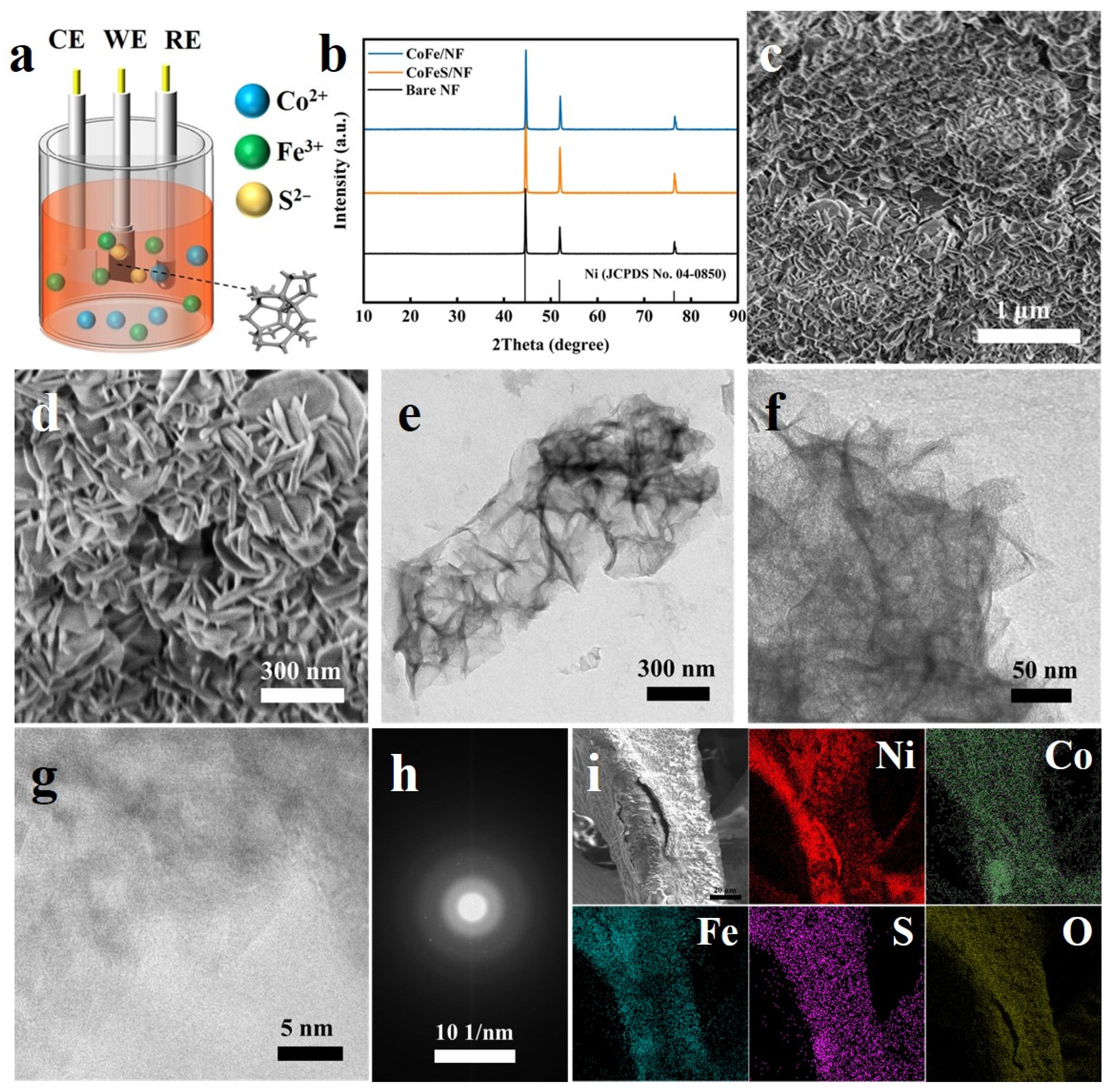
2.1. Characterization of Samples

Figure 1a schematically illustrates the fabrication process of CoFeS/NF via a one-step electrodeposition method. To elucidate the crystalline phase composition of the as-prepared samples, X-ray diffraction (XRD) analysis was performed, as shown in Figure 1b. Both CoFeS/NF and CoFe/NF exhibit XRD patterns nearly identical to those of the bare NF substrate, with three prominent diffraction peaks observed at 44.5°, 51.8°, and 76.7°, corresponding to the (111), (200), and (220) crystallographic planes of metallic Ni (JCPDS No. 04-0850) [39], respectively. Notably, no discernible diffraction peaks attributable to crystalline Co/Fe-based compounds or sulfides are detected, indicating the amorphous structural characteristics of both catalysts. Such amorphous features are advantageous for electrocatalytic applications, as they inherently expose abundant active sites and enhance structural flexibility, thereby promoting catalytic activity and long-term stability during UOR and OER processes [40,41,42].
Figure S1a presents the SEM image of CoFe/NF, revealing that the catalyst is homogeneously grown on the NF substrate, exhibiting a nanosheet-like morphology. The high-magnification SEM image (Figure S1b) further demonstrates that partial nanosheets aggregate into cluster-like particles through overlapping and stacking. TEM analysis (Figure S1c) corroborates the lamellar microstructure of CoFe/NF, with interlayer stacking observed in localized regions, consistent with the SEM findings. HRTEM (Figure S1d) shows no discernible lattice fringes, and the corresponding SAED pattern (inset) lacks distinct diffraction rings or spots, unambiguously confirming the amorphous nature of CoFe/NF. These observations align well with the XRD results, which also indicate the absence of long-range crystalline order in the catalyst.
As shown in Figure 1c,d, CoFeS/NF also exhibits a nanosheet-like architecture. Compared to CoFe/NF, the CoFeS/NF nanosheets display enhanced dispersion and structural homogeneity, with minimal stacking or aggregation into nanoparticles. This morphological optimization significantly increases the specific surface area of the catalyst, thereby exposing a greater density of accessible active sites. The TEM images (Figure 1e,f) further corroborate the well-defined nanosheet morphology of CoFeS/NF. Notably, abundant surface wrinkles are uniformly distributed across the nanosheets, contributing to additional surface area enlargement. HRTEM analysis (Figure 1g) reveals no discernible lattice fringes, while the corresponding SAED pattern (Figure 1h) exhibits a diffuse diffraction ring, both of which are characteristic of amorphous materials. These findings align with the XRD results, collectively confirming the non-crystalline nature of CoFeS/NF. Together, these results demonstrate the successful fabrication of amorphous CoFe/NF and CoFeS/NF catalysts via the one-step electrodeposition strategy.
The elemental mapping images of CoFe/NF (Figure S2a) reveal the homogeneous distribution of Ni, Co, Fe, and O elements across the NF substrate. Quantitative EDS analysis (Figure S2b) indicates a Co: Fe atomic ratio of approximately 3:1 on the catalyst surface, consistent with the stoichiometric ratios employed during synthesis. Similarly, the elemental mapping of CoFeS/NF (Figure 1i) demonstrates the uniform spatial distribution of Ni, Co, Fe, S, and O elements within the NF framework, while maintaining the Co: Fe atomic ratio near 3:1. Notably, sulfur incorporation accounts for 0.8 at.% of the total metallic content at the catalyst surface, as quantified by EDS (Figure S3).
To validate that sulfur doping enhances the specific surface area of amorphous cobalt–iron catalysts, Brunauer–Emmett–Teller (BET) surface area analysis was conducted on both CoFeS/NF and CoFe/NF. The nitrogen adsorption–desorption isotherms of the samples (Figure S4a,c) exhibit characteristic Type IV profiles, indicative of mesoporous materials. Quantitative analysis reveals BET-specific surface areas of 23.296 m2 g−1 for CoFe/NF and 44.634 m2 g−1 for CoFeS/NF, demonstrating that sulfur incorporation significantly increases the surface area due to the formation of more dispersed nanosheet architectures [43]. This structural optimization not only enlarges the electrochemically active area but also facilitates greater exposure of catalytic sites. Pore size distribution curves (Figure S4b,d) further confirm that both catalysts possess uniform mesoporous structures, with dominant pore diameters centered around 17 nm. The preserved mesoporosity ensures efficient mass transport of reactants and byproducts during electrocatalytic processes, synergistically enhancing overall performance [44].
The surface elemental composition and chemical states of the catalysts were further investigated by XPS. As shown in the survey scan (Figure 2a), the CoFeS/NF catalyst exhibits distinct peaks corresponding to Ni, Co, Fe, O, and S, confirming the successful incorporation of sulfur into the CoFe/NF matrix. Semi-quantitative analysis of the XPS data reveals the following atomic percentages: 24.77% Ni, 7.32% Co, 2.96% Fe, 0.29% S, and 64.66% O. Notably, sulfur accounts for 0.83% of the total metallic content, which aligns closely with the EDS-derived sulfur concentration (~0.8 at.%), validating the consistency of compositional characterization across multiple techniques.
The Ni 2p XPS spectrum of CoFeS/NF (Figure 2b) reveals a mixed valence state of nickel, predominantly comprising Ni2+ and Ni3+ species. Specifically, the peaks located at 875.19 eV and 856.71 eV correspond to the Ni3+ 2p1/2 and 2p3/2 orbitals, respectively, while those at 873.00 eV and 855.43 eV are attributed to Ni2+ 2p1/2 and 2p3/2 states [45]. Additionally, the presence of satellite peaks at 879.29 eV and 861.31 eV further corroborates the oxidized nature of nickel. Notably, compared to CoFe/NF, the Ni 2p peaks in CoFeS/NF exhibit a positive shift toward higher binding energies. This transition stems from sulfur-induced electron redistribution on the catalyst surface, which enhances the electronic effect and facilitates the formation of more highly valent metal active centers [46,47]. The Co 2p XPS spectrum of CoFeS/NF (Figure 2c) exhibits distinct spin–orbit doublets corresponding to Co 2p3/2 and Co 2p1/2 orbitals at binding energies of 781.17 eV and 796.46 eV, respectively, accompanied by satellite peaks at 785.74 eV and 802.85 eV. Peak deconvolution reveals two oxidation states of cobalt: the peaks at 780.98 eV (Co 2p3/2) and 796.26 eV (Co 2p1/2) are assigned to Co3+ species, while those at 782.53 eV (Co 2p3/2) and 797.78 eV (Co 2p1/2) correspond to Co2+. Notably, the Co 2p peaks in CoFeS/NF undergo a positive binding energy shift compared to CoFe/NF, attributed to sulfur-induced electron redistribution [48]. This electronic modulation stabilizes the higher oxidation state (Co3+), resulting in an increased Co3+/Co2+ ratio and enhanced catalytic activity. Figure 2d displays the Fe 2p XPS spectrum of CoFeS/NF, where the peaks at binding energies of 711.74 eV (Fe 2p3/2) and 723.35 eV (Fe 2p1/2) correspond to oxidized iron species [49]. Notably, these peaks exhibit a negative shift compared to CoFe/NF, suggesting sulfur-induced electron donation effects that modulate the local electronic environment of Fe.
The O 1s spectrum (Figure 2e) is deconvoluted into three components: OI at 530.58 eV (metal–xygen bonds, M–O), OII at 531.19 eV (oxygen vacancies, VO), and OIII at 532.31 eV (adsorbed hydroxyl/water species). Sulfur doping induces a positive shift in the OI peak, reflecting enhanced covalency of M–O bonds due to electron redistribution [50]. Figure 2f shows the S 2p spectra, and the sulfur in the sample mainly exists in the form of sulfate, indicating that the catalytic material undergoes oxidation in air to form the corresponding S–O bonds [51]. The above results demonstrate that the successful doping of S elements into the catalytic materials resulted in the redistribution of the surface charge of the samples and the generation of more metals in higher valence states (Ni3+ and Co3+) as active sites for the catalytic reactions [52].

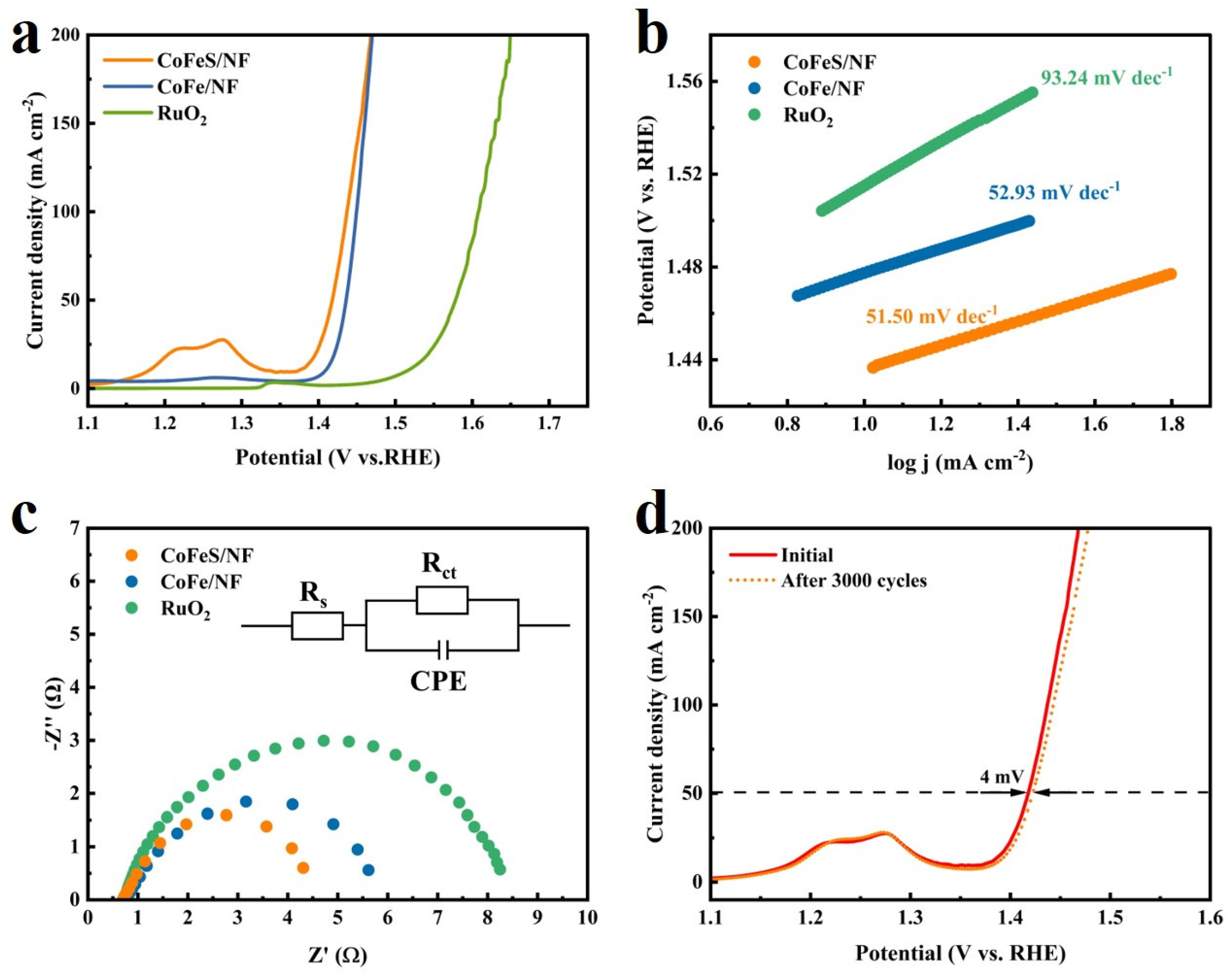
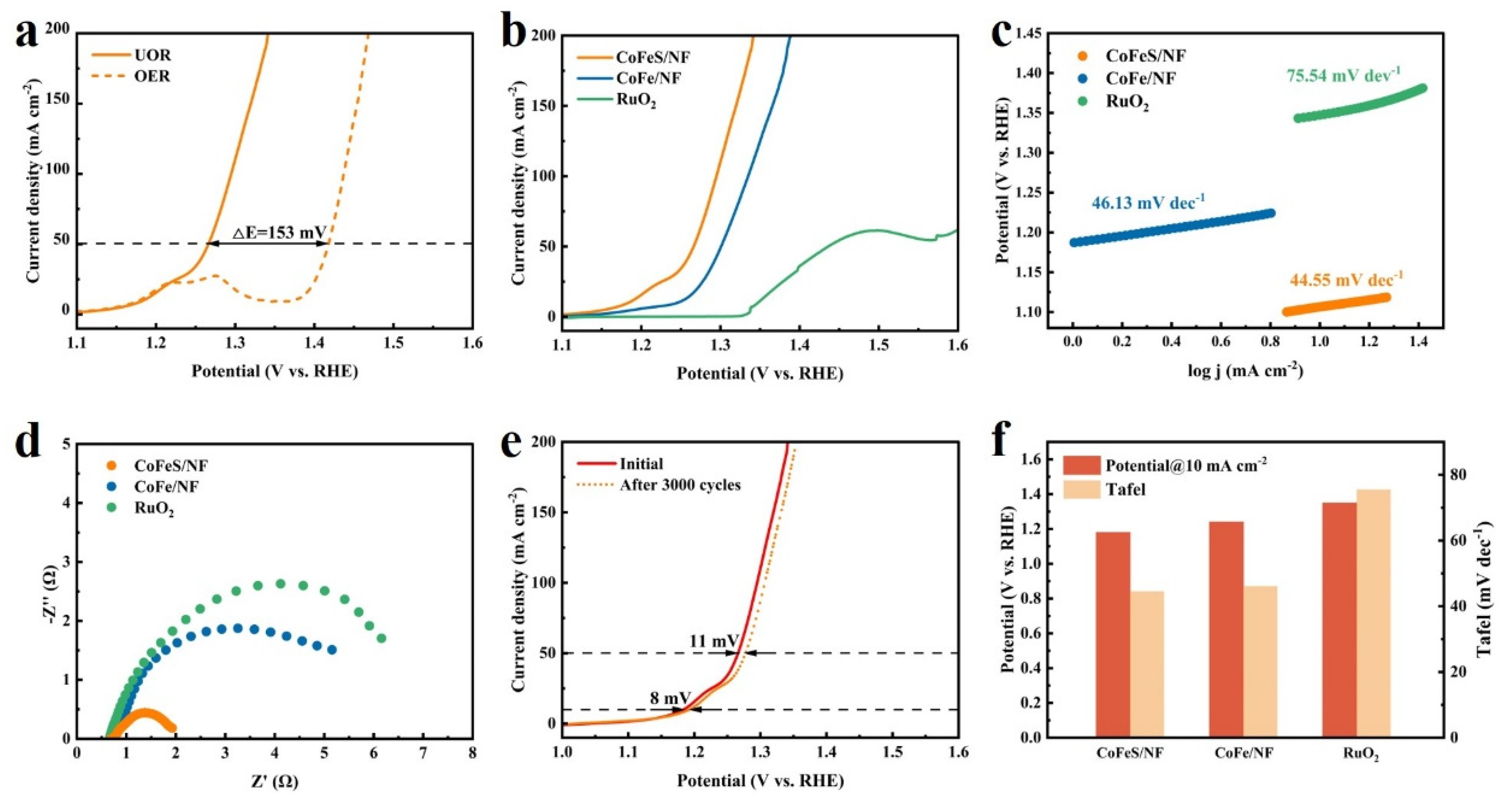
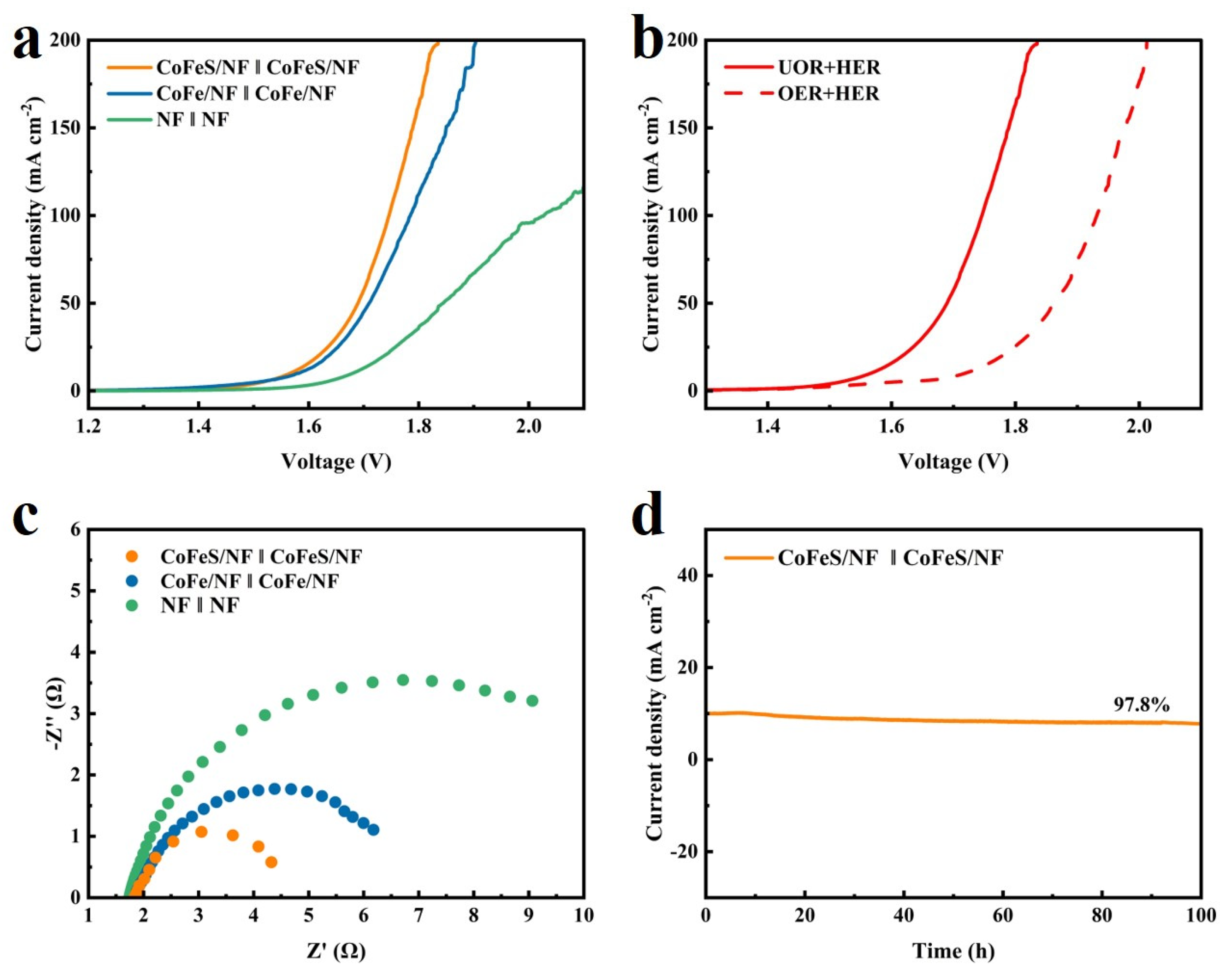
2.2. Electrochemical Testing of Samples

The HER performance of CoFeS/NF was evaluated in 1 M KOH electrolyte. As shown in Figure 3a, CoFeS/NF achieves an overpotential of 269.8 mV at 10 mA cm−2, which is comparable to that of CoFe/NF. This minimal difference suggests that sulfur doping, as a non-metallic element, contributes negligibly to enhancing cathodic HER kinetics. Although CoFeS/NF demonstrates moderate HER activity, its performance remains substantially inferior to the benchmark Pt/C catalyst (η10 = 45.8 mV), highlighting the need for further optimization. To investigate the influence of urea on HER behavior, Figure 3b compares the LSV polarization curves of CoFeS/NF in 1 M KOH and 1 M KOH + 0.5 M urea electrolytes. The addition of urea induces no significant shift in HER overpotentials, indicating that urea molecules do not interfere with the hydrogen adsorption/desorption processes under cathodic conditions. This observation aligns with prior studies reporting the inertness of urea in HER systems [53,54].
The Tafel slope serves as a critical indicator of reaction kinetics, where lower values correspond to faster catalytic processes. As depicted in Figure 3c, CoFeS/NF exhibits a charge transfer resistance of 5.16 Ω during HER, slightly smaller than that of CoFe/NF (6.63 Ω), indicating enhanced electron transfer kinetics at the electrolyte-catalyst interface. The Cdl was derived by fitting CV curves acquired in the non-faradaic region (Figure S5a,b). As shown in Figure S5c, the Cdl of CoFeS/NF (3.37 mF cm−2) is marginally lower than that of CoFe/NF (5.43 mF cm−2), suggesting comparable active site exposure despite sulfur-induced morphological refinements. To evaluate HER durability, CoFeS/NF was subjected to 3000 CV cycles in 1 M KOH. Figure 3d demonstrates exceptional stability, with the overpotential at 10 mA cm−2 increasing by merely 10 mV after cycling. This minimal degradation underscores the structural robustness of the amorphous CoFeS/NF catalyst under prolonged cathodic operation.
The OER performance of the catalysts was evaluated in 1 M KOH using a conventional three-electrode system. As shown in Figure 4a, CoFeS/NF achieves remarkably low overpotentials of 140 mV and 180 mV at current densities of 10 mA cm−2 and 50 mA cm−2, respectively. These values represent significant improvements compared to both CoFe/NF (Δη10 = −40 mV, Δη50 = −20 mV) and the benchmark RuO2 catalyst (Δη10 = −150 mV, Δη50 = −170 mV). The enhanced OER activity of CoFeS/NF is attributed to the synergistic effects of its amorphous architecture and sulfur-induced electronic modulation. The amorphous structure provides abundant undercoordinated active sites, while sulfur doping optimizes the adsorption energetics of oxygen-containing intermediates (e.g., NiOOH) by redistributing electron density across the Ni–Co–Fe matrix, thereby lowering the thermodynamic barrier for the rate-determining step. Figure 4b presents the Tafel slopes derived from OER data. The CoFeS/NF catalyst exhibits a Tafel slope of 51.50 mV dec−1, which is not only lower than that of CoFe/NF (52.93 mV dec−1) but also substantially smaller than the benchmark RuO2 (93.24 mV dec−1). These findings confirm that CoFeS/NF achieves enhanced OER kinetics, surpassing both its undoped counterpart and commercial RuO2. EIS analysis (Figure 4c) further corroborates the superior charge transfer efficiency of CoFeS/NF, with a charge transfer resistance of 4.03 Ω. This value is significantly smaller than those of CoFe/NF (5.37 Ω) and RuO2 (7.71 Ω), highlighting the accelerated electron transport kinetics enabled by sulfur doping.
CV scans in the non-faradaic region were performed for CoFeS/NF, CoFe/NF, and RuO2 (Figure S6a–c). The Cdl, derived by linear fitting of the capacitive current against scan rate (Figure S6d), reveals a Cdl value of 5.32 mF cm−2 for CoFeS/NF in OER, which is 1.3-fold higher than that of CoFe/NF (4.21 mF cm−2). This substantial increase confirms that the sulfur-induced highly dispersed nanosheet architecture of CoFeS/NF exposes a greater density of electrochemically active sites, directly contributing to its enhanced OER performance. To assess long-term operational stability, CoFeS/NF was subjected to 3000 CV cycles in 1 M KOH. As shown in Figure 4d, the catalyst exhibits exceptional durability, with a negligible overpotential increase in only 4 mV at 50 mA cm−2 post-cycling. This remarkable stability is attributed to the robust amorphous structure of CoFeS/NF, which resists corrosion and structural degradation under prolonged anodic polarization, outperforming crystalline counterparts that typically suffer from surface reconstruction and metal dissolution. Similarly, the long-term stability of Pt/C/NF and RuO2/NF was evaluated in a 1 M KOH electrolyte, as shown in Figure S7. Both catalysts showed poor stability, and the active phase gradually separated from the NF substrate within 20 h, resulting in a significant decrease in catalytic activity. These results further confirm that the drop-by-drop application method is unable to make a tight contact between the active component and the substrate, which is consistent with relevant studies [55].
The UOR performance of the catalysts was further evaluated in 1 M KOH + 0.5 M urea electrolyte. Figure 5a directly compares the electrocatalytic activity of CoFeS/NF for UOR and OER. Notably, UOR exhibits a significantly lower thermodynamic potential requirement, with a 153 mV reduction in applied potential at 50 mA cm−2 compared to OER. Furthermore, the onset potential of UOR coincides with the oxidation peak in OER corresponding to the Ni2+ → Ni3+ transition, strongly suggesting that Ni3+ species serve as the active centers for urea oxidation. This conclusion aligns with previous mechanistic studies [56,57,58], which identified high-valent Ni3+ as critical for breaking N–H bonds in urea molecules. Figure 5b compares the UOR polarization curves of CoFeS/NF, CoFe/NF, and RuO2. At 10 mA cm−2, CoFeS/NF achieves a remarkably low potential of 1.18 V (vs. RHE), outperforming CoFe/NF (1.24 V) and RuO2 (1.35 V). The superior UOR activity of CoFeS/NF arises from sulfur doping, which effectively promotes the electron transfer process and thus significantly enhances the UOR catalytic activity of the material. Figure 5c presents the Tafel slopes for UOR, providing direct evidence of the reaction kinetics. The CoFeS/NF catalyst exhibits a Tafel slope of 44.55 mV dec−1, which is not only lower than that of CoFe/NF (46.13 mV dec−1) but also significantly smaller than the RuO2 (75.54 mV dec−1). This result strongly demonstrates the accelerated reaction kinetics of CoFeS/NF, underpinning its superior catalytic performance. EIS analysis (Figure 5d) further reveals that CoFeS/NF achieves a remarkably low charge transfer resistance of 1.31 Ω, substantially lower than CoFe/NF (5.69 Ω) and RuO2 (6.69 Ω). A comparative analysis of key performance metrics at 10 mA cm−2 (Figure 5f) consolidates the exceptional UOR activity of CoFeS/NF. The catalyst requires a low applied potential of 1.18 V (vs. RHE) paired with its minimized Tafel slope (44.55 mV dec−1), outperforming both CoFe/NF and RuO2. These findings conclusively establish that sulfur incorporation optimizes electronic structure and reaction pathways, enabling CoFeS/NF to achieve state-of-the-art UOR performance.
To evaluate the density of active sites during UOR, CV was performed on CoFeS/NF, CoFe/NF, and RuO2 at scan rates ranging from 20 to 100 mV s−1 (Figure S8a–c). The Cdl derived from the linear fitting of capacitive currents (Figure S8d), reveals a Cdl value of 15.22 mF cm−2 for CoFeS/NF, which is 3.1-fold and 5.9-fold higher than those of CoFe/NF (4.99 mF cm−2) and RuO2 (2.60 mF cm−2), respectively. This substantial enhancement in Cdl directly correlates with the highly dispersed nanosheet morphology of CoFeS/NF, as evidenced by prior SEM and TEM analyses, which expose a greater abundance of electrochemically active sites. The synergistic interplay between sulfur doping and the amorphous nanostructure not only amplifies active site availability but also aligns with the increased specific surface area (44.6 m2 g−1) measured by BET analysis. These structural advantages collectively contribute to the superior UOR performance of CoFeS/NF, validating the hypothesis that sulfur-induced morphological refinement and electronic modulation synergistically optimize catalytic efficiency. Figure S9a,b present the LSV polarization curves of CoFeS/NF and CoFe/NF for the UOR at varying temperatures (25, 35, 45, and 55 °C). As shown in Figure S9c, CoFeS/NF exhibits a significantly lower Ea of 14.37 kJ mol−1 compared to CoFe/NF (15.56 kJ mol−1). This reduced activation energy indicates that CoFeS/NF requires a smaller energy barrier to stabilize reaction intermediates during UOR, thereby facilitating more favorable reaction kinetics. The enhanced catalytic efficiency of CoFeS/NF is attributed to sulfur-induced electronic modifications that weaken the binding strength of rate-limiting intermediates and promote charge transfer across the catalyst-electrolyte interface.
To assess the operational stability of CoFeS/NF, LSV curves were compared before and after 3000 CV cycles. As shown in Figure 5e, the overpotentials of CoFeS/NF at current densities of 10 mA cm−2 and 50 mA cm−2 increased by merely 8 mV and 11 mV, respectively, after prolonged cycling. This negligible degradation underscores the exceptional durability of CoFeS/NF under sustained UOR conditions, making it highly suitable for long-term catalytic applications. To further verify the structural stability of CoFeS/NF, a series of characterizations of the tested sample was performed. From the XRD patterns (Figure S10), the catalyst maintained its original structure after the UOR test, with only peaks belonging to the NF substrate. The SEM images (Figure S11) show that the UOR process caused surface roughening, but the overall nanosheet morphology remained intact without structural collapse or particle agglomeration. The retained structure ensures continuous exposure of active sites, enabling long-term catalytic efficiency. XPS analysis (Figure S12) further elucidated the evolution of the electronic valence states on the catalyst surface after UOR testing. The survey spectrum (Figure S12a) confirmed the presence of potassium on the catalyst surface, attributed to residual KOH from the electrolyte. The high-resolution spectra (Figure S12b–f) show a shift in the binding energies of all the elements, suggesting a dynamic redistribution of electrons during the catalytic process. Notably, the content of Ni3+ increased significantly after the UOR test, suggesting the in situ formation of NiOOH, which facilitates the catalytic reaction.
The overall urea electrolysis performance was evaluated using CoFeS/NF as both the cathode and anode in a two-electrode configuration. Figure 6a compares the LSV polarization curves of CoFeS/NF‖CoFeS/NF, CoFe/NF‖CoFe/NF, and NF‖NF systems. At a current density of 10 mA cm−2, the CoFeS/NF‖CoFeS/NF configuration achieves a remarkably low cell voltage of 1.56 V, outperforming CoFe/NF‖CoFe/NF (1.58 V) and NF‖NF (1.68 V). This enhanced performance underscores the synergistic advantages of sulfur doping in optimizing HER and UOR kinetics. Figure 6b directly contrasts the overall water splitting and urea electrolysis activities of CoFeS/NF‖CoFeS/NF. The urea-assisted system exhibits a significantly reduced voltage (Δη = 120 mV at 10 mA cm−2), demonstrating that UOR is a thermodynamically favorable alternative to the conventional OER. Figure 6c presents the EIS Nyquist plots for urea electrolysis. The CoFeS/NF‖CoFeS/NF system exhibits the smallest semicircle diameter, corresponding to a Rct of 2.76 Ω, significantly lower than those of CoFe/NF‖CoFe/NF (4.93 Ω) and NF‖NF (9.48 Ω). This minimal Rct confirms the accelerated charge transfer kinetics of the sulfur-doped catalyst, which facilitates efficient electron transport during urea electrolysis. To assess operational stability, the CoFeS/NF‖CoFeS/NF system was subjected to a 100 h chronopotentiometry test at a fixed current density of 10 mA cm−2. As shown in Figure 6d, the system retains 97.8% of its initial current density after prolonged operation, demonstrating exceptional durability. This stability is attributed to the corrosion-resistant amorphous structure and sulfur-stabilized active sites, which mitigate degradation under continuous electrochemical stress. The results collectively validate CoFeS/NF as a robust bifunctional catalyst for energy-efficient and sustainable urea electrolysis.

3. Materials and Methods

3.1. Chemicals and Materials

Nickel foam (NF; 16 cm × 8 cm) was purchased from Shanghai Hesheng Electric Co., Ltd. (Shanghai, China). Iron(III) nitrate nonahydrate (Fe(NO3)3·9H2O) was sourced from Tianjin Guangfu Fine Chemical Research Institute (Tianjin, China). Cobalt(II) nitrate hexahydrate (Co(NO3)2·6H2O), thiourea (CH4N2S), potassium hydroxide (KOH), isopropanol (C3H8O), ruthenium(IV) oxide (RuO2; CAS No. 12036-10-1), Nafion solution (5 wt%, CAS No. 31175-20-9), and acetylene black were procured from Shanghai Aladdin Biochemical Technology Co., Ltd. (Shanghai, China). Hydrochloric acid (HCl), anhydrous ethanol (C2H5OH; CAS No. 64-17-5), and urea (CO(NH2)2) were obtained from Sinopharm Chemical Reagent Co., Ltd. (Shanghai, China). All chemicals were of analytical reagent (AR) grade and used without further purification. Deionized water (18.2 MΩ·cm resistivity) was purified using a ZYPFT-2-20 T system (Sichuan Zhuoyue Water Treatment Equipment Co., Ltd., Chengdu, China).

3.2. Preparation of CoFe/NF and CoFeS/NF

The CoFe/NF catalyst was synthesized via a one-step electrodeposition method. First, a nickel foam substrate was cut into rectangular pieces (1 × 2 cm) and ultrasonically cleaned sequentially in 3 M HCl, anhydrous ethanol, and deionized water for 15 min each to remove surface oxides. Subsequently, an aqueous electrolyte solution was prepared by dissolving 6 mmol Co(NO3)2·6H2O and 2 mmol Fe(NO3)3·9H2O in 200 mL of deionized water under vigorous stirring. Electrodeposition was performed using a three-electrode configuration at room temperature: the cleaned NF as the working electrode, a platinum foil counter electrode, and a Hg/HgO reference electrode. The deposition process was carried out in chronoamperometry (CA) mode at a constant potential of −1.0 V (vs. Hg/HgO) for 150 s. Finally, the as-deposited sample was thoroughly rinsed with deionized water and dried overnight at room temperature, yielding an amorphous cobalt–iron catalyst denoted as CoFe/NF.
The CoFeS/NF catalyst was similarly synthesized via the one-step electrodeposition method described above, with the addition of 0.4 mmol CH4N2S into the electrolyte under vigorous stirring prior to deposition. This sulfur precursor introduction enabled the incorporation of sulfur species into the CoFe matrix during electrodeposition. Following identical electrochemical parameters and post-treatment procedures as CoFe/NF, the resultant catalyst exhibited an amorphous cobalt–iron–sulfur structure, designated as CoFeS/NF.

3.3. Preparation of Pt/C/NF and RuO2/NF

A measured amount of 7 mg Pt/C (or RuO2) and 3 mg acetylene black were dispersed in a mixed solvent containing 490 μL deionized water and 490 μL isopropanol. The mixture was homogenized via 30 min of ultrasonication, followed by the addition of 20 μL Nafion solution (5 wt%), and further ultrasonicated for another 30 min to form a homogeneous catalyst ink. Subsequently, a 200 μL aliquot of the ink was drop-casted onto a pretreated NF substrate and dried at room temperature for 12 h to obtain the Pt/C/NF or RuO2/NF electrodes.

3.4. Characterization of Materials

The crystalline phases of the catalysts were characterized by X-ray diffraction (XRD; DX-2700BH, Rigaku Corporation, Akishima, Japan) using Cu Kα radiation (λ = 1.5406 Å) at a scanning rate of 5° min−1 over a 2θ range of 10° to 90°, with an operating voltage of 40 kV and current of 30 mA. Surface morphology and microstructure were analyzed using field-emission scanning electron microscopy (FE-SEM; Nova NanoSEM 450, FEI Company, Hillsboro, OR, USA) coupled with energy-dispersive X-ray spectroscopy (EDS). Transmission electron microscopy (TEM; JEM-2100, JEOL Ltd., Tokyo, Japan), including high-resolution TEM (HRTEM) and selected-area electron diffraction (SAED), was employed to examine lattice fringes and crystallographic features. Chemical states and surface elemental composition were investigated by X-ray photoelectron spectroscopy (XPS; ESCALAB 250Xi, Thermo Fisher Scientific, Waltham, MA, USA) under ultrahigh vacuum (8 × 10⁻¹⁰ Pa) with monochromatic Al Kα excitation (hν = 1486.6 eV). All XPS spectra were charge-corrected by referencing the adventitious carbon C 1s peak at 284.8 eV. Specific surface areas and pore size distributions were determined via nitrogen adsorption–desorption isotherms measured at 77 K using a surface area analyzer (NOVA 4400e, Quantachrome Instruments, Boynton Beach, FL, USA). Prior to measurements, samples were degassed at 100 °C for 6 h under high-purity nitrogen flow to remove physisorbed contaminants.

3.5. Electrochemical Characterization

All electrochemical measurements were performed at room temperature (22 °C) using a CHI760E electrochemical workstation with a conventional three-electrode configuration. The as-prepared catalyst served as the working electrode, while a platinum foil and a Hg/HgO electrode (immersed in 1 M KOH) were employed as the counter and reference electrodes, respectively. Tests were conducted in 1 M KOH electrolyte with and without 0.5 M urea additive. Prior to measurements, the electrolyte was purged with high-purity N2 gas for 30 min to remove dissolved oxygen. All measured potentials were converted to the reversible hydrogen electrode (RHE) scale using the Nernst equation:
E(RHE) = E(Hg⁄HgO) + 0.059 × pH + 0.098,
where E(Hg⁄HgO) represents the experimentally recorded potential versus the Hg/HgO reference electrode, and the pH value of 1 M KOH was calculated as 14 [59].
(1) Linear Sweep Voltammetry (LSV)
The catalytic performance of different materials was evaluated by comparing the overpotentials (η) required to achieve specific current densities (10, 50, and 100 mA cm−2) derived from LSV curves. Lower η values (closer to 0 V) indicate superior catalytic activity. All LSV measurements were performed at a scan rate of 5 mV s−1 with 90% automatic iR compensation. For the OER and UOR, the potential window was set between 0.2 and 0.8 V versus the Hg/HgO reference electrode. Conversely, the hydrogen evolution reaction (HER) was analyzed within a potential range of −0.8 to −1.6 V (vs. Hg/HgO).
(2) Tafel Analysis
The Tafel slope serves as a critical indicator of the kinetic efficiency of the electrochemical process. Derived by fitting the polarization data to the Tafel equation:
η = a + b log|j|,
where η denotes the overpotential (V), j represents the current density (mA cm−2), b is the Tafel slope (mV dec−1), and a is a reaction-specific constant. Lower Tafel slope values correspond to faster reaction kinetics, reflecting enhanced catalytic activity [60].
(3) Cyclic Voltammetry (CV) Analysis
The double-layer capacitance (Cdl), a quantitative indicator of electrochemically active sites, is directly proportional to the density of accessible catalytic centers. Cdl values were determined by analyzing CV curves acquired within the non-faradaic potential region at varying scan rates (20, 40, 60, 80, and 100 mV s−1). At each scan rate (v), the capacitive current was calculated as half the difference between the anodic (ja) and cathodic (jc) current densities at the midpoint potential [61]. The Cdl value corresponds to the slope of the linear regression obtained by plotting j a j c 2 against v, as described by
C d l = j a j c / 2 v .
(4) Electrochemical Impedance Spectroscopy (EIS)
EIS provides critical insights into the charge transfer kinetics of electrocatalytic processes, where a lower charge transfer resistance (Rct) indicates faster reaction kinetics. The EIS measurements were conducted at a constant current density of 10 mA cm−2, with an AC amplitude of 10 mV over a frequency range of 10−2 to 105 Hz. The resulting Nyquist plots were analyzed using an equivalent circuit model to quantify Rct, which reflects the intrinsic kinetic barrier for electron transfer at the catalyst-electrolyte interface.
(5) Chronoamperometric (I-T) Stability Testing
Long-term stability is a critical parameter for assessing the practical viability of electrocatalysts. In this work, the durability of the catalysts was evaluated via chronoamperometry (CA) under a constant current density of 10 mA cm−2 for 100 h. The retained current density and potential drift over time were quantified to determine the degradation kinetics and operational robustness of the catalysts under sustained electrochemical stress.
(6) Activation Energy (Ea) Analysis
The activation energy (Ea) represents the minimum energy barrier required to initiate a chemical reaction, reflecting the thermodynamic difficulty of forming reaction intermediates during electrocatalytic processes. A higher Ea indicates greater energy demands and slower reaction kinetics. In this study, Ea was determined using the Arrhenius-derived relationship under constant overpotential (η):
log i k 1 / T η = E a 2.3 R
where ik denotes the kinetic current density (mA cm−2) at a given potential, T is the absolute temperature of the electrolyte (K), and R is the universal gas constant (R = 8.314 J mol−1 K−1). By measuring ik at varying temperatures, the slope of the linear plot of log ik versus 1/T yields Ea, providing insights into the rate-limiting steps of the catalytic mechanism [62].

4. Conclusions

This study presents a novel sulfur-doped cobalt–iron catalyst (CoFeS/NF) with significant potential for electrocatalytic urea decomposition toward hydrogen production. The incorporation of sulfur induces profound electronic restructuring and morphological refinement, transforming the catalyst into a highly dispersed nanosheet architecture, thereby exposing abundant active sites and enabling efficient UOR and OER catalytic activities in alkaline media. The experimental results demonstrate that CoFeS/NF achieves a remarkably low applied potential of 1.18 V at 10 mA cm−2 for UOR, outperforming both undoped CoFe/NF (1.24 V) and the benchmark RuO2 catalyst (1.35 V). Notably, the catalyst exhibits exceptional operational durability alongside rapid charge transfer kinetics. These attributes stem from sulfur-induced electronic redistribution, which stabilizes high-valent metal species (Ni3+/Co3+) while mitigating corrosion through structural flexibility. By integrating energy-efficient hydrogen generation with urea-rich wastewater remediation, this work establishes a dual-functional strategy for sustainable energy and environmental applications. The findings provide critical insights into anion doping engineering for optimizing multi-metallic electrocatalysts, offering a scalable pathway toward replacing conventional energy-intensive water electrolysis.

Supplementary Materials

The following supporting information can be downloaded at https://www.mdpi.com/article/10.3390/catal15030285/s1.

Author Contributions

S.L. and L.Y. contributed equally to this work. S.L., Z.X. and X.X. designed this work; S.L., L.Y. and Z.W. carried out the synthesis, characterization, and electrochemical experiments; S.L., Z.X. and X.X. wrote the manuscript. The analysis of the experimental data, discussions of the results, and preparation of the manuscript were all carried out collaboratively by all authors. All authors have read and agreed to the published version of the manuscript.

Funding

This work was supported by the Postgraduate Research and Innovation Foundation of Yunnan University (ZC-23234488).

Data Availability Statement

No data were used for the research described in the article.

Conflicts of Interest

The authors declare no conflict of interest.

References

  1. Akadiri, A.C.; Saint Akadiri, S.; Gungor, H. The role of natural gas consumption in Saudi Arabia’s output and its implication for trade and environmental quality. Energy Policy 2019, 129, 230–238. [Google Scholar] [CrossRef]
  2. Child, M.; Koskinen, O.; Linnanen, L.; Breyer, C. Sustainability guardrails for energy scenarios of the global energy transition. Renew. Sustain. Energy Rev. 2018, 91, 321–334. [Google Scholar] [CrossRef]
  3. Lewis, N.S.; Nocera, D.G. Powering the planet: Chemical challenges in solar energy utilization. Proc. Natl. Acad. Sci. USA 2006, 103, 15729–15735. [Google Scholar] [CrossRef] [PubMed]
  4. Turner, J.A. Sustainable Hydrogen Production. Science 2004, 305, 972–974. [Google Scholar] [CrossRef] [PubMed]
  5. Dresselhaus, M.S.; Thomas, I.L. Alternative energy technologies. Nature 2001, 414, 332–337. [Google Scholar] [CrossRef]
  6. Chu, S.; Cui, Y.; Liu, N. The path towards sustainable energy. Nat. Mater. 2017, 16, 16–22. [Google Scholar] [CrossRef]
  7. Carmo, M.; Fritz, D.L.; Merge, J.; Stolten, D. A comprehensive review on PEM water electrolysis. Int. J. Hydrogen Energy 2013, 38, 4901–4934. [Google Scholar] [CrossRef]
  8. Xiao, X.; Yang, L.J.; Sun, W.P.; Chen, Y.; Yu, H.; Li, K.K.; Jia, B.H.; Zhang, L.; Ma, T.Y. Electrocatalytic Water Splitting: From Harsh and Mild Conditions to Natural Seawater. Small 2022, 18, 2105830. [Google Scholar] [CrossRef]
  9. Shi, L.N.; Cui, L.T.; Ji, Y.R.; Xie, Y.; Zhu, Y.R.; Yi, T.F. Towards high-performance electrocatalysts: Activity optimization strategy of 2D MXenes-based nanomaterials for water-splitting. Coord. Chem. Rev. 2022, 469, 214668. [Google Scholar] [CrossRef]
  10. Sun, H.; Li, L.; Chen, Y.; Kim, H.; Xu, X.; Guan, D.; Hu, Z.; Zhang, L.; Shao, Z.; Jung, W. Boosting ethanol oxidation by NiOOH-CuO nano-heterostructure for energy-saving hydrogen production and biomass upgrading. Appl. Catal. B Environ. Energy 2023, 325, 122388. [Google Scholar] [CrossRef]
  11. Cao, Z.; Zhou, T.; Ma, X.; Shen, Y.; Deng, Q.; Zhang, W.; Zhao, Y. Hydrogen Production from Urea Sewage on NiFe-Based Porous Electrocatalysts. ACS Sustain. Chem. Eng. 2020, 8, 11007–11015. [Google Scholar] [CrossRef]
  12. Zhu, L.; Huang, J.; Meng, G.; Wu, T.; Chen, C.; Tian, H.; Chen, Y.; Kong, F.; Chang, Z.; Cui, X.; et al. Active site recovery and N-N bond breakage during hydrazine oxidation boosting the electrochemical hydrogen production. Nat. Commun. 2023, 14, 1997. [Google Scholar] [CrossRef]
  13. Qiao, L.L.; Zhu, A.Q.; Liu, D.; Feng, J.X.; Chen, Y.Y.; Chen, M.P.; Zhou, P.F.; Yin, L.H.; Wu, R.C.; Ng, K.W.; et al. Crystalline phosphides/amorphous oxides composite for energy-saving hydrogen production assisted by efficient urea oxidation reaction. Chem. Eng. J. 2022, 454, 140380. [Google Scholar] [CrossRef]
  14. Qiu, Y.F.; Dai, X.F.; Wang, Y.P.; Ji, X.Y.; Ma, Z.; Liu, S.Q. The polyoxometalates mediated preparation of phosphate-modified NiMoO4-x with abundant O-vacancies for H2 production via urea electrolysis. J. Colloid Interface Sci. 2022, 629, 297–309. [Google Scholar] [CrossRef] [PubMed]
  15. Patil, S.A.; Shrestha, N.K.; Inamdar, A.I.; Bathula, C.; Jung, J.; Hussain, S.; Nazir, G.; Kaseem, M.; Im, H.; Kim, H. Bimetallic Cu/Fe MOF-Based Nanosheet Film via Binder-Free Drop-Casting Route: A Highly Efficient Urea-Electrolysis Catalyst. Nanomaterials 2022, 12, 1916. [Google Scholar] [CrossRef]
  16. Zhang, Q.; Sun, M.S.; Zhu, J.; Yang, S.D.; Chen, L.; Yang, X.L.; Wang, P.; Li, K.; Xue, F.N.; Lu, Y.; et al. New strategy to synthesize oxygen vacancy-rich CoFe nanoneedles for overall water splitting and urea electrolysis. Chem. Eng. J. 2021, 432, 134275. [Google Scholar] [CrossRef]
  17. Zheng, Z.C.; Wu, D.; Chen, L.; Chen, S.; Wan, H.; Chen, G.; Zhang, N.; Liu, X.H.; Ma, R.Z. Collaborative optimization of thermodynamic and kinetic for Ni-based hydroxides in electrocatalytic urea oxidation reaction. Appl. Catal. B Environ. 2023, 340, 123214. [Google Scholar] [CrossRef]
  18. Jiang, H.; Sun, M.Z.; Wu, S.L.; Huang, B.L.; Lee, C.S.; Zhang, W.J. Oxygen-Incorporated NiMoP Nanotube Arrays as Efficient Bifunctional Electrocatalysts For Urea-Assisted Energy-Saving Hydrogen Production in Alkaline Electrolyte. Adv. Funct. Mater. 2021, 31, 2104951. [Google Scholar] [CrossRef]
  19. Huang, C.J.; Xu, H.M.; Shuai, T.Y.; Zhan, Q.N.; Zhang, Z.J.; Li, G.R. Modulation Strategies for the Preparation of High-Performance Catalysts for Urea Oxidation Reaction and Their Applications. Small 2023, 19, 2301130. [Google Scholar] [CrossRef]
  20. Diao, Y.X.; Liu, Y.S.; Hu, G.X.; Zhao, Y.Y.; Qian, Y.H.; Wang, H.D.; Shi, Y.; Li, Z. NiFe nanosheets as urea oxidation reaction electrocatalysts for urea removal and energy-saving hydrogen production. Biosens. Bioelectron. 2022, 211, 114380. [Google Scholar] [CrossRef]
  21. Ge, J.H.; Kuang, J.E.; Xiao, Y.H.; Guan, M.H.; Yang, C.Z. Recent development of nickel-based catalysts and in situ characterization techniques for mechanism understanding of the urea oxidation reaction. Surf. Interfaces 2023, 41, 103230. [Google Scholar] [CrossRef]
  22. Huang, C.J.; Zhan, Q.N.; Xu, H.M.; Zhu, H.R.; Shuai, T.Y.; Li, G.R. Fe-Doped Ni2P/NiSe2 Composite Catalysts for Urea Oxidation Reaction (UOR) for Energy-Saving Hydrogen Production by UOR-Assisted Water Splitting. Inorg. Chem. 2024, 63, 8925–8937. [Google Scholar] [CrossRef]
  23. Zhang, J.Y.; Wang, H.M.; Tian, Y.F.; Yan, Y.; Xue, Q.; He, T.; Liu, H.F.; Wang, C.D.; Chen, Y.; Xia, B.Y. Anodic hydrazine oxidation assists energy-efficient hydrogen evolution over a bifunctional cobalt perselenide nanosheet electrode. Angew. Chem. Int. Ed. 2018, 57, 7649–7653. [Google Scholar] [CrossRef]
  24. Wang, S.L.; Zhao, L.Y.; Li, J.X.; Tian, X.L.; Wu, X.; Feng, L.G. High valence state of Ni and Mo synergism in NiS2-MoS2 hetero-nanorods catalyst with layered surface structure for urea electrocatalysis. J. Energy Chem. 2021, 66, 483–492. [Google Scholar] [CrossRef]
  25. Liang, Y.H.; Liu, Q.; Asiri, A.M.; Sun, X.P. Enhanced electrooxidation of urea using NiMoO4·xH2O nanosheet arrays on Ni foam as anode. Electrochim. Acta 2014, 153, 456–460. [Google Scholar] [CrossRef]
  26. Yu, Z.Y.; Lang, C.C.; Gao, M.R.; Chen, Y.; Fu, Q.Q.; Duan, Y.; Yu, S.H. Ni–Mo–O nanorod-derived composite catalysts for efficient alkaline water-to-hydrogen conversion via urea electrolysis. Energy Environ. Sci. 2018, 11, 1890–1897. [Google Scholar] [CrossRef]
  27. Zhuo, X.Y.; Jiang, W.J.; Yu, T.Q.; Qian, G.F.; Chen, J.L.; Yang, H.F.; Yin, S.B. Crystalline-Amorphous Ni3S2-NiMoO4 Heterostructure for Durable Urea Electrolysis-Assisted Hydrogen Production at High Current Density. ACS Appl. Mater. Interfaces 2022, 14, 46481–46490. [Google Scholar] [CrossRef]
  28. Chen, J.L.; Wang, Y.M.; Qian, G.F.; Yu, T.Q.; Wang, Z.L.; Luo, L.; Shen, F.; Yin, S.B. In Situ Growth of Volcano-like FeIr Alloy on Nickel Foam as Efficient Bifunctional Catalyst for Overall Water Splitting at High Current Density. Chem. Eng. J. 2021, 421, 129892. [Google Scholar] [CrossRef]
  29. Wang, Z.J.; Guo, P.; Liu, M.; Guo, C.; Liu, H.J.; Wei, S.X.; Zhang, J.; Lu, X.Q. Rational Design of Metallic NiTex (x = 1 or 2) as Bifunctional Electrocatalysts for Efficient Urea Conversion. ACS Appl. Energy Mater. 2019, 2, 3363–3372. [Google Scholar] [CrossRef]
  30. Zhu, X.J.; Dou, X.Y.; Dai, J.; An, X.D.; Guo, Y.Q.; Zhang, L.D.; Tao, S.; Zhao, J.Y.; Chu, W.S.; Zeng, X.C.; et al. Metallic Nickel Hydroxide Nanosheets Give Superior Electrocatalytic Oxidation of Urea for Fuel Cells. Angew. Chem. Int. Ed. 2016, 55, 12465–12469. [Google Scholar] [CrossRef]
  31. Ren, H.N.; Yu, L.X.; Yang, L.P.; Huang, Z.H.; Kang, F.Y.; Lv, R.T. Efficient electrocatalytic overall water splitting and structural evolution of cobalt iron selenide by one-step electrodeposition. J. Energy Chem. 2021, 60, 194–201. [Google Scholar] [CrossRef]
  32. Shit, S.; Bolar, S.; Murmu, N.C.; Kuila, T. Tailoring the bifunctional electrocatalytic activity of electrodeposited molybdenum sulfide/iron oxide heterostructure to achieve excellent overall water splitting. Chem. Eng. J. 2021, 417, 129333. [Google Scholar] [CrossRef]
  33. Liu, S.S.; Ma, L.J.; Li, J.S. Facile preparation of amorphous NiFe hydroxide by corrosion engineering for electrocatalytic water and urea oxidation. J. Alloys Compd. 2022, 936, 168271. [Google Scholar] [CrossRef]
  34. Song, Y.L.; Huang, J.L.; Tang, C.L.; Wang, T.; Liu, Y.S.; He, X.S.; Xie, C.P.; Chen, G.; Deng, C.F.; He, Z.B. Improved Urea Oxidation Performance via Interface Electron Redistributions of the NiFe(OH)x/MnO2/NF p-p Heterojunction. Small 2024, 20, 2403612. [Google Scholar] [CrossRef] [PubMed]
  35. Zhang, Y.; Cheng, C.Q.; Kuai, C.G.; Sokaras, D.; Zheng, X.L.; Sainio, S.; Lin, F.; Dong, C.K.; Nordlund, D.; Du, X.W. Unveiling the critical role of the Mn dopant in a NiFe(OH)2 catalyst for water oxidation. J. Mater. Chem. A 2020, 8, 17471–17476. [Google Scholar] [CrossRef]
  36. Li, Y.L.; Jia, B.M.; Chen, B.Y.; Liu, Q.L.; Cai, M.K.; Xue, Z.Q.; Fan, Y.N.; Wang, H.P.; Su, C.Y.; Li, G.Q. MOF-derived Mn doped porous CoP nanosheets as efficient and stable bifunctional electrocatalysts for water splitting. Dalton Trans. 2018, 47, 14679–14685. [Google Scholar] [CrossRef]
  37. Luo, M.; Liu, S.Q.; Zhu, W.W.; Ye, G.Y.; Wang, J.; He, Z. An electrodeposited MoS2-MoO3-x/Ni3S2 heterostructure electrocatalyst for efficient alkaline hydrogen evolution. Chem. Eng. J. 2021, 428, 131055. [Google Scholar] [CrossRef]
  38. Qin, H.Y.; Ye, Y.K.; Li, J.H.; Jia, W.Q.; Zheng, S.Y.; Cao, X.J.; Lin, G.L.; Jiao, L.F. Synergistic engineering of doping and vacancy in Ni(OH)2 to boost urea electrooxidation. Adv. Funct. Mater. 2022, 33, 2209698. [Google Scholar] [CrossRef]
  39. Yi, X.; He, X.; Yin, F.; Chen, B.; Li, G.; Yin, H. Amorphous Ni-Fe-Se hollow nanospheres electrodeposited on nickel foam as a highly active and bifunctional catalyst for alkaline water splitting. Dalton Trans. 2020, 49, 6764–6775. [Google Scholar] [CrossRef]
  40. Li, S.R.; Zhang, Y.P.; Yu, X.; Wang, Z.L.; Zhang, G.F.; Zhao, Z.Y.; Yan, Z.Y.; Xiao, X.C. One-step electrodeposition synthesis of amorphous NiCoFe(OH)x/NF as an efficient catalyst for urea-assisted overall water splitting. Electrochim. Acta 2023, 463, 142803. [Google Scholar] [CrossRef]
  41. Yao, L.C.; Zhang, H.M.; Humayun, M.; Fu, Y.J.; Xu, X.F.; Feng, C.D.; Wang, C.D. Constructing Nanoporous Crystalline/Amorphous NiFe2O4/NiO Electrocatalyst for High Efficiency OER/UOR. J. Alloys Compd. 2022, 936, 168206. [Google Scholar] [CrossRef]
  42. Wang, Z.L.; Li, S.R.; Zhang, G.F.; Yu, X.; Shi, Y.; Zhang, Y.P.; Xiao, X.C. Facile synthesis of FeCoW oxides: Effects of amorphous structure, electronic configuration and catalytic sites on water oxidation. J. Alloys Compd. 2022, 933, 167787. [Google Scholar] [CrossRef]
  43. Mosallaei, H.; Hadadzadeh, H.; Ensafi, A.A.; Mousaabadi, K.Z.; Weil, M.; Foelske, A.; Sauer, M. Evaluation of HER and OER electrocatalytic activity over RuO2–Fe2O3 nanocomposite deposited on HrGO nanosheets. Int. J. Hydrogen Energy 2022, 48, 1813–1830. [Google Scholar] [CrossRef]
  44. Raja, A.; Son, N.; Swaminathan, M.; Kang, M. Electrochemical behavior of heteroatom doped on reduced graphene oxide with RuO2 for HER, OER, and supercapacitor applications. J. Taiwan Inst. Chem. Eng. 2022, 138, 104471. [Google Scholar] [CrossRef]
  45. He, W.; Zhang, R.; Liu, H.; Hao, Q.; Li, Y.; Zheng, X.; Liu, C.; Zhang, J.; Xin, H. Atomically Dispersed Silver Atoms Embedded in NiCo Layer Double Hydroxide Boost Oxygen Evolution Reaction. Small 2023, 19, 2301610. [Google Scholar] [CrossRef]
  46. Ren, L.P.; Yang, D.; Li, J.Q.; Li, H.S.; Yang, J.H. Nitrogen doped carbon fiber supported nickel phosphide for efficient electrocatalytic overall urea splitting. Appl. Surf. Sci. 2023, 624, 157173. [Google Scholar] [CrossRef]
  47. Xie, H.; Feng, Y.F.; He, X.Y.; Zhu, Y.; Li, Z.Y.; Liu, H.H.; Zeng, S.Y.; Qian, Q.Z.; Zhang, G.Q. Construction of Nitrogen-Doped Biphasic Transition-Metal Sulfide Nanosheet Electrode for Energy-Efficient Hydrogen Production via Urea Electrolysis. Small 2022, 19, 2207425. [Google Scholar] [CrossRef]
  48. Shamloofard, M.; Shahrokhian, S. Morphology Modulation and Phase Transformation of Manganese-Cobalt Carbonate Hydroxide Caused by Fluoride Doping and Its Effect on Boosting the Overall Water Electrolysis. Inorg. Chem. 2023, 62, 1178–1191. [Google Scholar] [CrossRef]
  49. Shang, X.; Yan, K.; Lu, S.; Dong, B.; Gao, W.; Chi, J.; Liu, Z.; Chai, Y.; Liu, C. Controlling electrodeposited ultrathin amorphous Fe hydroxides film on V-doped nickel sulfide nanowires as efficient electrocatalyst for water oxidation. J. Power Sources 2017, 363, 44–53. [Google Scholar] [CrossRef]
  50. Zou, D.; Yi, Y.; Song, Y.; Guan, D.; Xu, M.; Ran, R.; Wang, W.; Zhou, W.; Shao, Z. The BaCe0.16Y0.04Fe0.8O3-δ nanocomposite: A new high-performance cobalt-free triple-conducting cathode for protonic ceramic fuel cells operating at reduced temperatures. J. Mater. Chem. A 2022, 10, 5381–5390. [Google Scholar] [CrossRef]
  51. Li, Q.; Chen, B.; Huang, L.; Zhu, S.; Qian, Y.; Wu, D.; Luo, S.; Xie, A. S-doped Ni(Fe)OOH bifunctional electrocatalysts for overall water splitting. Int. J. Hydrogen Energy 2023, 51, 1392–1406. [Google Scholar] [CrossRef]
  52. Zhang, L.S.; Wang, L.P.; Lin, H.P.; Liu, Y.X.; Ye, J.Y.; Wen, Y.Z.; Chen, A.; Wang, L.; Ni, F.L.; Zhou, Z.Y.; et al. A Lattice-Oxygen-Involved Reaction Pathway to Boost Urea Oxidation. Angew. Chem. Int. Ed. 2019, 58, 16820–16825. [Google Scholar] [CrossRef] [PubMed]
  53. Yu, T.Q.; Xu, Q.L.; Chen, J.L.; Qian, G.F.; Zhuo, X.Y.; Yang, H.F.; Yin, S.B. Boosting urea-assisted water splitting by constructing sphere-flower-like NiSe2-NiMoO4 heterostructure. Chem. Eng. J. 2022, 449, 137791. [Google Scholar] [CrossRef]
  54. Xu, H.; Liao, Y.; Gao, Z.F.; Qing, Y.; Wu, Y.Q.; Xia, L.Y. A branch-like Mo-doped Ni3S2 nanoforest as a high-efficiency and durable catalyst for overall urea electrolysis. J. Mater. Chem. A 2021, 9, 3418–3426. [Google Scholar] [CrossRef]
  55. Lebedeva, O.; Kultin, D.; Zakharov, V.; Kuznetsova, I.; Aslanov, L.; Kustov, L. Triazine derivatives as metal-free electrocatalysts: Do three nitrogen atoms mimic a metal? Sustain. Energy Fuels 2024, 9, 1464–1479. [Google Scholar] [CrossRef]
  56. Li, J.N.; Li, J.L.; Liu, T.; Chen, L.; Li, Y.F.; Wang, H.L.; Chen, X.R.; Gong, M.; Liu, Z.P.; Yang, X.J. Deciphering and suppressing over-oxidized nitrogen in nickel-catalyzed urea electrolysis. Angew. Chem. Int. Ed. 2021, 60, 26656–26662. [Google Scholar] [CrossRef]
  57. Zhu, D.D.; Zhang, H.Y.; Miao, J.H.; Hu, F.X.; Wang, L.; Tang, Y.J.; Qiao, M.; Guo, C.X. Strategies for designing more efficient electrocatalysts towards the urea oxidation reaction. J. Mater. Chem. A 2022, 10, 3296–3313. [Google Scholar] [CrossRef]
  58. Jiao, Y.; Zheng, Y.; Jaroniec, M.; Qiao, S.Z. Design of Electrocatalysts for Oxygen- and Hydrogen-Involving Energy Conversion Reactions. Chem. Soc. Rev. 2015, 44, 2060–2086. [Google Scholar] [CrossRef]
  59. Kordek, K.; Yin, H.J.; Rutkowski, P.; Zhao, H.J. Cobalt-based composite films on electrochemically activated carbon cloth as high performance overall water splitting electrodes. Int. J. Hydrogen Energy 2018, 44, 23–33. [Google Scholar] [CrossRef]
  60. Lai, Y.Q.; Li, Y.; Jiang, L.X.; Xu, W.; Lv, X.J.; Li, J.; Liu, Y.X. Electrochemical behaviors of co-deposited Pb/Pb-MnO2 composite anode in sulfuric acid solution—Tafel and EIS investigations. J. Electroanal. Chem. 2012, 671, 16–23. [Google Scholar] [CrossRef]
  61. Wu, J.; Yu, Z.J.; Zhang, Y.Y.; Niu, S.Q.; Zhao, J.Y.; Li, S.W.; Xu, P. Understanding the effect of second metal on CoM (M = Ni, Cu, Zn) metal-organic frameworks for electrocatalytic oxygen evolution reaction. Small 2021, 17, 2105150. [Google Scholar] [CrossRef] [PubMed]
  62. Wang, L.L.; He, W.; Yin, D.D.; Xie, Y.R.; Zhang, H.L.; Ma, Q.L.; Yu, W.S.; Yang, Y.; Dong, X.T. Achieving Efficient Urea Electrolysis by Spatial Confinement Effect and Heterostructure. Chem. Eng. J. 2023, 462, 142254. [Google Scholar] [CrossRef]
Figure 1. (a) Schematic synthesis of NiCoFeS/NF, (b) XRD patterns of NiCoFeS/NF, NiCoFe/NF and Bare NF, (c,d) SEM, (e,f) TEM images, (g) HRTEM image, (h) SAED pattern, and (i) elemental mapping of NiCoFeS/NF.
Catalysts 15 00285 g001
Figure 2. XPS spectra of NiCoFe/NF and NiCoFeS/NF. (a) Full spectrum, (b) Ni 2p, (c) Co 2p, (d) Fe 2p, (e) O 1s, and (f) S 2p.
Catalysts 15 00285 g002
Figure 3. HER performance tests. (a) LSV curves of NiCoFeS/NF, NiCoFe/NF and Pt/C in 1 M KOH, (b) LSV curves of NiCoFeS/NF in 1 M KOH and 1 M KOH + 0.5 M urea, (c) Nyquist diagram, and (d) LSV curves of NiCoFeS/NF before and after 3000 CV cycles.
Catalysts 15 00285 g003
Figure 4. OER performance tests of NiCoFeS/NF, NiCoFe/NF and RuO2 in 1 M KOH. (a) LSV curve, (b) Tafel slope, (c) Nyquist chart, and (d) NiCoFeS/NF LSV curve before and after 3000 CV cycles.
Catalysts 15 00285 g004
Figure 5. UOR performance test of NiCoFeS/NF, NiCoFe/NF and RuO2 1 M KOH + 0.5 M urea. (a) LSV curve of UOR and OER, (b) LSV curve, (c) Tafel slope, (d) Nyquist diagram, (e) NiCoFeS/NF LSV curve before and after 3000 CV cycles, (f) comparison of Tafel slope and potential at 10 mA cm−2.
Catalysts 15 00285 g005
Figure 6. NiCoFeS/NF‖NiCoFeS/NF, NiCoFe/NF‖NiCoFe/NF and NF‖NF electrolytic properties of all urea. (a) LSV curve, (b) NiCoFeS/NF‖NiCoFeS/NF LSV curve for fully electrolyzed water and urea, (c) Nyquist diagram, (d) 100 h stability curve for NiCoFeS/NF‖NiCoFeS/NF at 10 mA cm−2.
Catalysts 15 00285 g006
Disclaimer/Publisher’s Note: The statements, opinions and data contained in all publications are solely those of the individual author(s) and contributor(s) and not of MDPI and/or the editor(s). MDPI and/or the editor(s) disclaim responsibility for any injury to people or property resulting from any ideas, methods, instructions or products referred to in the content.

