
Selective Synthesis of a Gasoline Fraction from CO and H2 on a Co-SiO2/ZSM-5/Al2O3 Catalyst

 ,
,  and
and
Abstract
:
1. Introduction
2. Results and Discussion
3. Materials and Methods
3.1. Catalyst Preparation
3.2. Catalyst Characterization
3.3. Catalyst Characterization
4. Conclusions
Author Contributions
Funding
Data Availability Statement
Conflicts of Interest
References
- Li, N.; Jiao, F.; Pan, X.; Chen, Y.; Feng, J.; Li, G.; Bao, X. High-quality gasoline directly from syngas by dual metal oxide–zeolite (OX-ZEO) catalysis. Angew. Chem. Int. Ed. 2019, 58, 7400–7404. [Google Scholar] [CrossRef] [PubMed]
- Pan, X.; Jiao, F.; Miao, D.; Bao, X. Oxide–zeolite-based composite catalyst concept that enables syngas chemistry beyond Fischer–Tropsch synthesis. Chem. Rev. 2021, 121, 6588–6609. [Google Scholar] [CrossRef] [PubMed]
- Lischiner, I.; Malova, O.; Tarasov, A.; Krotov, M.; Korobtsev, S.; Potapkin, B. Obtaining of Environmental Motor Fuel with Low Durene Content of Dimethyl Ether. Ecol. Ind. Russ. 2017, 21, 20–23. [Google Scholar] [CrossRef]
- Khadzhiev, S.N.; Vytnova, L.A. The first commercial Fischer-Tropsch processes in Germany. Pet. Chem. 2008, 48, 133–149. [Google Scholar] [CrossRef]
- Li, J.; He, Y.; Tan, L.; Zhang, P.; Peng, X.; Oruganti, A.; Yang, G.; Abe, H.; Wang, Y.; Tsubaki, N. Integrated tuneable synthesis of liquid fuels via Fischer–Tropsch technology. Nat. Catal. 2018, 1, 787–793. [Google Scholar] [CrossRef]
- Keil, F.J. Methanol-to-hydrocarbons: Process technology. Microporous Mesoporous Mater. 1999, 29, 49–66. [Google Scholar] [CrossRef]
- Topp-Jørgensen, J. Topsøe integrated gasoline synthesis–The TIGAS process. In Studies in Surface Science and Catalysis; Elsevier: Amsterdam, The Netherlands, 1988; Volume 36, pp. 293–305. [Google Scholar] [CrossRef]
- Mysov, V.M.; Reshetnikov, S.I.; Stepanov, V.G.; Ione, K.G. Synthesis gas conversion into hydrocarbons (gasoline range) over bifunctional zeolite-containing catalyst: Experimental study and mathematical modelling. Chem. Eng. J. 2005, 107, 63–71. [Google Scholar] [CrossRef]
- Fu, T.; Chang, J.; Shao, J.; Li, Z. Fabrication of a nano-sized ZSM-5 zeolite with intercrystalline mesopores for conversion of methanol to gasoline. J. Energy Chem. 2017, 26, 139–146. [Google Scholar] [CrossRef]
- Matieva, Z.M.; Kolesnichenko, N.V.; Snatenkova, Y.M.; Maksimov, A.L. Conversion of syngas to triptane-rich liquid hydrocarbons via oxygenates. Fuel 2021, 304, 121407. [Google Scholar] [CrossRef]
- Xing, C.; Li, M.; Zhang, G.; Noreen, A.; Fu, Y.; Yao, M.; Lu, C.; Gao, X.; Yang, R.; Amoo, C.C. Syngas to isoparaffins: Rationalizing selectivity over zeolites assisted by a predictive isomerization model. Fuel 2021, 285, 119233. [Google Scholar] [CrossRef]
- Zhu, C.; Bollas, G.M. Gasoline selective Fischer-Tropsch synthesis in structured bifunctional catalysts. Appl. Catal. B Environ. 2018, 235, 92–102. [Google Scholar] [CrossRef]
- Wang, C.; Fang, W.; Wang, L.; Xiao, F.S. Fischer-Tropsch reaction within zeolite crystals for selective formation of gasoline-ranged hydrocarbons. J. Energy Chem. 2021, 54, 429–433. [Google Scholar] [CrossRef]
- Cheng, S.; Mazonde, B.; Zhang, G.; Javed, M.; Dai, P.; Cao, Y.; Tu, S.; Wu, J.; Lu, C.; Xing, C.; et al. Co-based MOR/ZSM-5 composite zeolites over a solvent-free synthesis strategy for improving gasoline selectivity. Fuel 2018, 223, 354–359. [Google Scholar] [CrossRef]
- Javed, M.; Cheng, S.; Zhang, G.; Dai, P.; Cao, Y.; Lu, C.; Yang, R.; Xing, C.; Shan, S. Complete encapsulation of zeolite supported Co based core with silicalite-1 shell to achieve high gasoline selectivity in Fischer-Tropsch synthesis. Fuel 2018, 215, 226–231. [Google Scholar] [CrossRef]
- Zhu, C.; Gamliel, D.P.; Valla, J.A.; Bollas, G.M. Fischer-Tropsch synthesis in monolith catalysts coated with hierarchical ZSM-5. Appl. Catal. B Environ. 2021, 284, 119719. [Google Scholar] [CrossRef]
- Sineva, L.V.; Gorokhova, E.O.; Gryaznov, K.O.; Ermolaev, I.S.; Mordkovich, V.Z. Zeolites as a tool for intensification of mass transfer on the surface of a cobalt Fischer–Tropsch synthesis catalyst. Catal. Today 2021, 378, 140–148. [Google Scholar] [CrossRef]
- Sineva, L.; Mordkovich, V.; Asalieva, E.; Smirnova, V. Zeolite-Containing Co Catalysts for Fischer–Tropsch Synthesis with Tailor-Made Molecular-Weight Distribution of Hydrocarbons. Reactions 2023, 4, 359–380. [Google Scholar] [CrossRef]
- Kibby, C.; Jothimurugesan, K.; Das, T.; Lacheen, H.S.; Rea, T.; Saxton, R.J. Chevron’s gas conversion catalysis-hybrid catalysts for wax-free Fischer–Tropsch synthesis. Catal. Today 2013, 215, 131–141. [Google Scholar] [CrossRef]
- Yakovenko, R.E.; Savost’yanov, A.P.; Narochnyi, G.B.; Soromotin, V.N.; Zubkov, I.N.; Papeta, O.P.; Svetogorov, R.D.; Mitchenko, S.A. Preliminary evaluation of a commercially viable Co-based hybrid catalyst system in Fischer-Tropsch synthesis combined with hydroprocessing. Catal. Sci. Technol. 2020, 10, 7613–7629. [Google Scholar] [CrossRef]
- Yakovenko, R.E.; Zubkov, I.N.; Bakun, V.G.; Agliullin, M.R.; Saliev, A.N.; Savost’yanov, A.P. Bifunctional Cobalt Catalyst for the Synthesis of Waxy Diesel Fuel by the Fischer–Tropsch Method: From Development to Commercialization. Part 1: Selection of the Industrial Sample of the Zeolite Component HZSM-5. Catal. Ind. 2021, 13, 230–238. [Google Scholar] [CrossRef]
- Narochnyi, G.B.; Yakovenko, R.E.; Savost’yanov, A.P.; Bakun, V.G. Experience in introducing a cobalt catalyst technology for the synthesis of hydrocarbons from CO and H2. Catal. Ind. 2016, 8, 139–144. [Google Scholar] [CrossRef]
- Savost’yanov, A.P.; Narochnyi, G.B.; Yakovenko, R.E.; Saliev, A.N.; Sulima, S.I.; Zubkov, I.N.; Nekroenko, S.V.; Mitchenko, S.A. Synthesis of low-pour-point diesel fuel in the presence of a composite cobalt-containing catalyst. Petrol. Chem. 2017, 57, 1186–1189. [Google Scholar] [CrossRef]
- Adeleke, A.A.; Liu, X.; Lu, X.; Moyo, M.; Hildebrandt, D. Cobalt hybrid catalysts in Fischer-Tropsch synthesis. Rev. Chem. Eng. 2020, 36, 437–457. [Google Scholar] [CrossRef]
- Gholami, Z.; Tišler, Z.; Rubáš, V. Recent advances in Fischer-Tropsch synthesis using cobalt-based catalysts: A review on supports, promoters, and reactors. Catal. Rev. 2021, 63, 512–595. [Google Scholar] [CrossRef]
- Sineva, L.V.; Asalieva, E.Y.; Mordkovich, V.Z. The role of zeolite in the Fischer–Tropsch synthesis over cobalt–zeolite catalysts. Russ. Chem. Rev. 2015, 84, 1176. [Google Scholar] [CrossRef]
- Sineva, L.V.; Nalivaiko, E.O.; Gryaznov, K.O.; Mordkovich, V.Z. Role of Zeolites in Heat and Mass Transfer in Pelletized Multifunctional Cobalt-Based Fischer–Tropsch Catalysts. Kinet. Catal. 2022, 63, 321–329. [Google Scholar] [CrossRef]
- Yakovenko, R.E.; Zubkov, I.N.; Bakun, V.G.; Savost’yanov, A.P. Combined Synthesis and Hydroprocessing of Hydrocarbons over Co/SiO2+ZSM-5+Al2O3 Catalysts Promoted by Nickel. Pet. Chem. 2021, 61, 516–526. [Google Scholar] [CrossRef]
- Abdellatief, T.M.; Ershov, M.A.; Kapustin, V.M.; Abdelkareem, M.A.; Kamil, M.; Olabi, A.G. Recent trends for introducing promising fuel components to enhance the anti-knock quality of gasoline: A systematic review. Fuel 2021, 291, 120112. [Google Scholar] [CrossRef]
- Blinova, I.O.; Glukhova, V.A. Features of ignition and combustion of fuels in gasoline engines. Theory Pract. Mod. Sci. 2020, 9–11. [Google Scholar]
- Ershov, M.; Potanin, D.; Gueseva, A.; Abdellatief, T.M.; Kapustin, V.M. Novel strategy to develop the technology of high-octane alternative fuel based on low-octane gasoline Fischer-Tropsch process. Fuel 2020, 261, 116330. [Google Scholar] [CrossRef]
- Yakovenko, R.E.; Zubkov, I.N.; Bakun, V.G.; Papeta, O.P.; Savostyanov, A.P. Effects of SiO2/Al2O3 Ratio in ZSM-5 Zeolite on the Activity and Selectivity of a Bifunctional Cobalt Catalyst for Synthesis of Low-Pour-Point Diesel Fuels from CO and H2. Pet. Chem. 2022, 62, 101–111. [Google Scholar] [CrossRef]
- PDF-2. The Powder Diffraction File TM. International Center for Diffraction Data (ICDD). PDF-2 Release 2012. 2014. Available online: www.icdd.com (accessed on 10 August 2023).
- Young, R.A. The Rietveld Method; Oxford University Press: Oxford, UK, 1995; 298p. [Google Scholar]
- Schanke, D.; Vada, S.; Blekkan, E.A.; Hilmen, A.M.; Hoff, A.; Holmen, A. Study of Pt-promoted cobalt CO hydrogenation catalysts. J. Catal. 1995, 156, 85–95. [Google Scholar] [CrossRef]
- Prieto, G.; Martínez, A.; Concepción, P.; Moreno-Tost, R. Cobalt particle size effects in Fischer–Tropsch synthesis: Structural and in situ spectroscopic characterisation on reverse micelle-synthesised Co/ITQ-2 model catalysts. J. Catal. 2009, 266, 129–144. [Google Scholar] [CrossRef]
- Qie, Y.; Liu, Y.; Kong, F.; Yang, Z.; Yang, H. High coercivity cobalt carbide nanoparticles as electrocatalysts for hydrogen evolution reaction. Nano Res. 2022, 15, 3901–3906. [Google Scholar] [CrossRef]
- Alex, P.; Majumdar, S.; Kishor, J.; Sharma, I.G. Synthesis of cobalt nanocrystals in aqueous media and its characterization. Mater. Sci. Appl. 2011, 2, 1307–1312. [Google Scholar] [CrossRef]


| Characteristics of the Porous Structure | Co0 Particle Size, nm | ||||
|---|---|---|---|---|---|
| SBET, m2/g | SEXT, m2/g | Vmicro, cm3/g | VƩ, cm3/g | XRD | TEM |
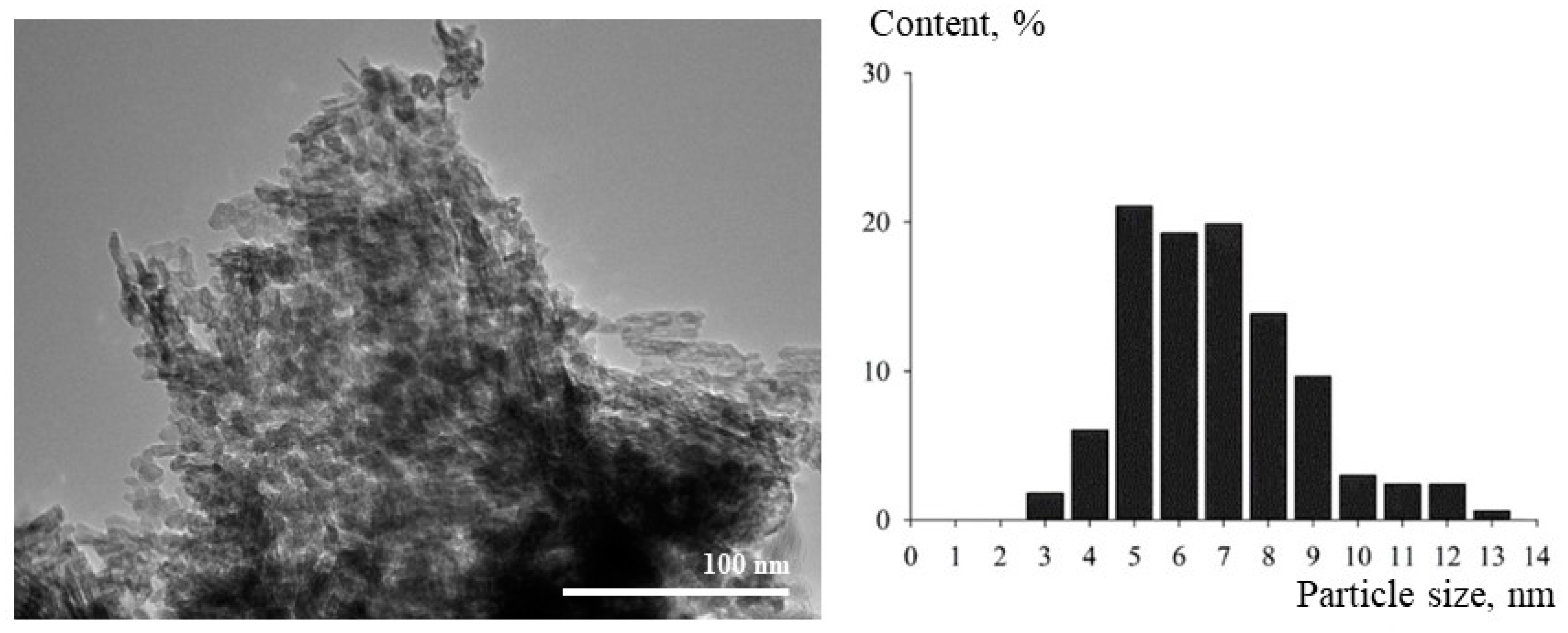
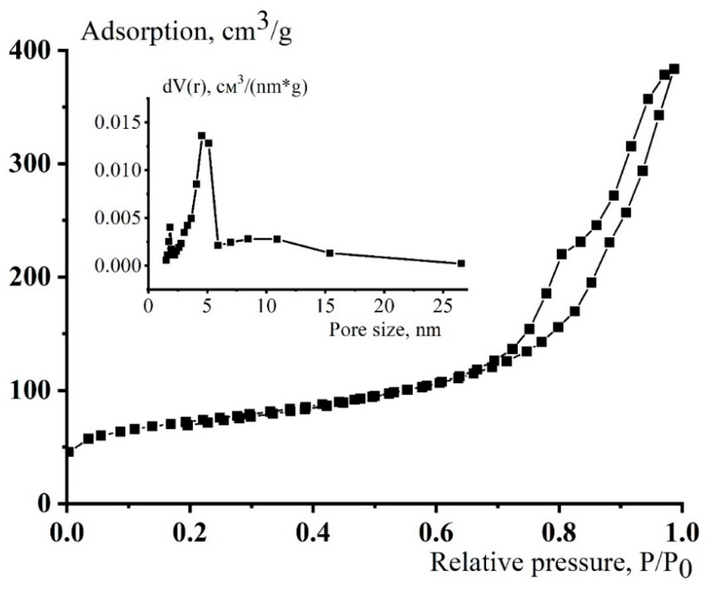
| 245 | 187 | 0.03 | 0.59 | 8.0 | 8 ± 2 |
| Pressure, MPa | CO Conversion, % | Selectivity for Hydrocarbons, % | iso/n Ratio | The Ratio of o/p in the Fraction C5–C10 | Productivity for Hydrocarbons, kg/(m3cat h) | |||
|---|---|---|---|---|---|---|---|---|
| C5+ | C5–C10 | C5+ | C5–C10 | C5+ | C5–C10 | |||
| Temperature 240 °C | ||||||||
| 0.5 | 55.1 | 63.7 | 69.6 | 4.35 | 4.75 | 3.19 | 80.7 | 56.2 |
| 1.0 | 62.7 | 70.8 | 67.0 | 2.08 | 3.19 | 2.72 | 97.0 | 65.0 |
| 2.0 | 75.6 | 67.1 | 54.3 | 0.76 | 0.76 | 1.46 | 106.0 | 57.5 |
| Temperature 250 °C | ||||||||
| 1.0 | 74.1 | 70.1 | 73.3 | 2.70 | 3.64 | 2.15 | 113.5 | 83.2 |
| 2.0 | 85.9 | 72.8 | 62.2 | 1.06 | 1.09 | 1.98 | 130.3 | 81.0 |
| Sample No. | Working Time, h | Average CO Conversion, % During Operation | Selectivity, % | Average Productivity According to C5+, kg/(m3cat h) | |||
|---|---|---|---|---|---|---|---|
| CH4 | C2–C4 | C5+ | CO2 | ||||
| 1 | 0–95 | 78.3 | 19.9 | 12.9 | 65.6 | 1.6 | 113.8 |
| 2 | 96–161 | 71.2 | 28.9 | 16.3 | 52.7 | 2.1 | 76.9 |
| 3 | 162–241 | 76.1 | 27.1 | 15.5 | 55.3 | 2.1 | 87.5 |
| 4 | 242–340 | 73.6 | 27.8 | 17.1 | 53.1 | 2.0 | 81.2 |
| 5 | 341–396 | 71.6 | 33.1 | 16.1 | 46.4 | 4.4 | 69.6 |
| 1–5 | 0–396 | 75.2 | 26.7 | 15.6 | 55.5 | 2.2 | 86.0 |
| Products | Group Composition of Hydrocarbons, % wt. | iso/n | o/p | ||
|---|---|---|---|---|---|
| C5–C10 | C11–C18 | C19+ | |||
| n-alkanes | 12.3 | 7.2 | 1.1 | 2.3 | 1.14 |
| Iso-alkanes | 14.2 | 10.6 | 1.3 | ||
| Alkenes | 9.0 | 0.5 | 0.1 | ||
| Branched alkenes | 29.7 | 13.7 | 0.3 | ||
| Total | 65.2 | 32.0 | 2.8 | ||
| Indicator | Actual Value | Requirement GOST P 51105-2020 | Method of Determination |
|---|---|---|---|
| Octane number (research method) not less than | 78.5 | 92 | GOST P 52947-2019 |
| Volume fraction of benzene, %, max | absent | 5.0 (1.0) | Chromatographically |
| Volume fraction of aromatic hydrocarbons, %, not more than | absent | 42.0 (35.0) | Chromatographically |
| Density at 15 °C, kg/m3 | 710.2 | 725–780 | GOST P 51069-97 |
| Net calorific value, kJ/kg | 43,780 | - | GOST 21261-2021 |
| Iodine number, g of iodine per 100 g of fuel | 11.8 | - | GOST 2070-82 |
| Volume fraction of hydrocarbon olefins, %, not more than | 53 | 18 | Chromatographically |
| Saturated vapor pressure, kPa | 41.2 | min. 45.0 | GOST 33157-2014 |
| Fractional composition, % vol. at temperature | GOST 2177-99 | ||
| 70 °C | 10.2 | 15–50 (48) | |
| 100 °C | 39.4 | 40–70 | |
| 150 °C | 84.7 | not less than 75 | |
| End of boiling, °C. | 185.5 | not higher than 215 | |
| Volume fraction of the residue in the flask, % vol. | 1.0 | not more than 2.0 |
| Catalyst | P, MPa | τ, h | t, °C | XCO, % | Selectivity, % | Octane Number | |||||||
|---|---|---|---|---|---|---|---|---|---|---|---|---|---|
| CO2 | CH4 | C2–C4 | C5–C11 | C12+ | Cn | Co | Ciso | ||||||
| Co-Al2O3/SiO2/HZSM-5/Al2O3 | 1.0 | 396 | 250 | 75.2 | 2.2 | 26.7 | 15.6 | 41.5 | 14.0 | 20.5 | 9.5 | 69.9 | 78.5 |
| Co/SiO2 + ZSM-5 [1] | 1.0 | 6 | 260 | 67.9 | 2.3 | 13.5 | 20.5 | 63.5 | 2.5 | 43.4 | 19.5 | 37.1 | 87 |
| Chevron [2] | 2.0 | n.d. | 220 | 50 | 0.9 | 12.2 | 11. | 75.6 | n.d. | n.d. | n.d. | n.d. | |
Disclaimer/Publisher’s Note: The statements, opinions and data contained in all publications are solely those of the individual author(s) and contributor(s) and not of MDPI and/or the editor(s). MDPI and/or the editor(s) disclaim responsibility for any injury to people or property resulting from any ideas, methods, instructions or products referred to in the content. |
© 2023 by the authors. Licensee MDPI, Basel, Switzerland. This article is an open access article distributed under the terms and conditions of the Creative Commons Attribution (CC BY) license (https://creativecommons.org/licenses/by/4.0/).
Share and Cite
Yakovenko, R.E.; Narochnyi, G.B.; Zubkov, I.N.; Bozhenko, E.A.; Kataria, Y.V.; Svetogorov, R.D.; Savost’yanov, A.P. Selective Synthesis of a Gasoline Fraction from CO and H2 on a Co-SiO2/ZSM-5/Al2O3 Catalyst. Catalysts 2023, 13, 1314. https://doi.org/10.3390/catal13091314
Yakovenko RE, Narochnyi GB, Zubkov IN, Bozhenko EA, Kataria YV, Svetogorov RD, Savost’yanov AP. Selective Synthesis of a Gasoline Fraction from CO and H2 on a Co-SiO2/ZSM-5/Al2O3 Catalyst. Catalysts. 2023; 13(9):1314. https://doi.org/10.3390/catal13091314
Chicago/Turabian StyleYakovenko, Roman E., Grigory B. Narochnyi, Ivan N. Zubkov, Ekaterina A. Bozhenko, Yash V. Kataria, Roman D. Svetogorov, and Alexander P. Savost’yanov. 2023. "Selective Synthesis of a Gasoline Fraction from CO and H2 on a Co-SiO2/ZSM-5/Al2O3 Catalyst" Catalysts 13, no. 9: 1314. https://doi.org/10.3390/catal13091314
APA StyleYakovenko, R. E., Narochnyi, G. B., Zubkov, I. N., Bozhenko, E. A., Kataria, Y. V., Svetogorov, R. D., & Savost’yanov, A. P. (2023). Selective Synthesis of a Gasoline Fraction from CO and H2 on a Co-SiO2/ZSM-5/Al2O3 Catalyst. Catalysts, 13(9), 1314. https://doi.org/10.3390/catal13091314