Article

S–Modified MXene as a Catalyst for Accelerated Tetracycline Hydrochloride Electrocatalytic Degradation via ·OH and Active Chlorine Triggering Promotion

1
College of Chemical Engineering, Huaqiao University, Xiamen 361021, China
2
Xiamen Engineering Research Center of Industrial Wastewater Biochemical Treatment, Xiamen 361021, China
3
Fujian Provincial Research Center of Industrial Wastewater Biochemical Treatment, Huaqiao University, Xiamen 361021, China
4
Xiamen Research Academy of Environmental Science, Xiamen 361021, China
5
Department of Environmental Engineering, National I-Lan University, Yilan 260007, Taiwan
*
Authors to whom correspondence should be addressed.
Catalysts 2023, 13(9), 1237; https://doi.org/10.3390/catal13091237
Submission received: 21 July 2023 / Revised: 18 August 2023 / Accepted: 24 August 2023 / Published: 25 August 2023

Abstract

:
S–modified MXene (Ti3C2Tx@S–5) was prepared to improve the catalytic activity of MXene in the electrocatalytic degradation of tetracycline hydrochloride (TC). Here, S groups in the form of Ti–S and S–O species were anchored onto MXene, resulting in superior conductivity and surface activity. Ti3C2Tx@S–5 exhibited an excellent performance of 100% TC degradation under the conditions of 25 °C, a pH of 6, a TC concentration of 10 mg L−1, and an applied current of 20 mA. Radical quenching and EPR analyses revealed that ·O2 and 1O2 played dominant roles in Ti3C2Tx@S–5 and Ti3C2Tx systems. Furthermore, S modification promoted the triggering of ·OH and active chlorine, which contributed to the acceleration of TC degradation. The involvement of these active substances in degradation pathways was further proven. This research advances the S modification of MXene and improves TC degradation by promoting the triggering of ·OH and active chlorine, broadening the applicability of MXene material.

Graphical Abstract

1. Introduction

Anode–dependent electrocatalytic technology, an effective approach to pollution control, is widely used in the advanced treatment of toxic and refractory organic wastewater. In general, the crucial process of the generation of highly oxidative active substrates [1], including hydroxyl radicals, singlet oxygen, and superoxide, determines the performance of electrocatalytic technology and relies on the polarity, surface active sites, and electron transfer capacity of anode materials.
MXenes with conductivities up to 10,000 s cm−1 [2] and high surface areas are distinct from MAX (Mn+1AXn, where M represents a transition metal; A stands for IIIA or IVA elements; and X indicates C or N) and are regarded as effective anode materials [3]. The terminal edge groups of –F, –O, and –OH, which could adjust the distortion of the MXene structure and consequently influence catalytic performance, are introduced via the chemical etching of IIIA or IVA elements (typically Si, Al, Ge, or Sn). The literature states that Ti3C2TX with an electrophilic terminal –F or –OH group exhibits high surface area, considerable chemical stability, high conductivity, hydrophilicity, and environmental compatibility [4,5,6]. Tang, Q. et al. [7] reported that Ti3C2F2 and Ti3C2(OH)2 monolayers possess various conductive properties that are largely dependent on the spatial arrangement of surface –F and –OH groups. Thus, in consideration of the urgent concerns regarding performance improvement, the modification of terminal edge groups is desired to adjust the properties of MXenes at the molecular level.
Currently, MXenes introduced with –N and –S terminal edge groups exhibit tunable electronic functions and promising capacity for the promotion of properties. The introduction of –N and –S terminal edge groups can not only increase the interlayer spacing of Ti3C2TX but can also effectively improve electrochemical performance. N–doped MXene and S@Ti3C2Tx films [8] have all been recently proven to present high conductivity and capacity (489 mA h g−1), excellent cycling performance (415 mA h g−1 after 280 cycles), and desirable Coulombic efficiency (>99%) [9].
Inspired by the attractive contribution of terminal edge group modification, S–modified MXene was constructed as a novel anode catalyst for electrocatalytic degradation. X-ray diffraction (XRD), Raman, cyclic voltammetry (CV), electrochemical impedance spectroscopy (EIS), and X-ray photoelectron spectroscopy (XPS) characterizations were performed with unmodified MXene for comparison to evaluate the changes in the properties of MXene modified via S introduction. The improvement in conductivity and surface activity accounted for the superior degradation performance of Ti3C2Tx@S–5. Then, radical quenching experiments and EPR analysis were further conducted to deepen the mechanistic discussion. ·O2, 1O2, ·OH, and active chlorine were identified as participating substances, and the pathway of TC degradation behavior was further proposed.

2. Results and Discussion

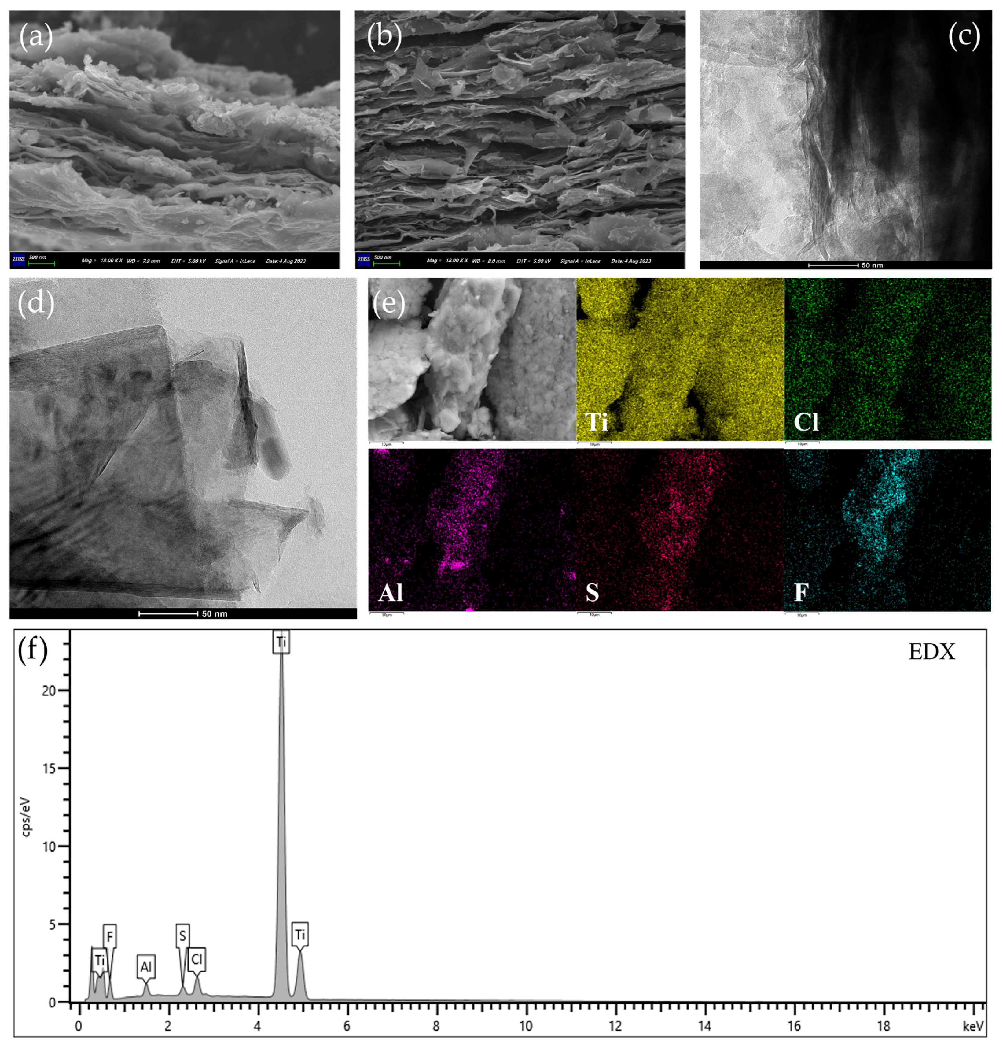
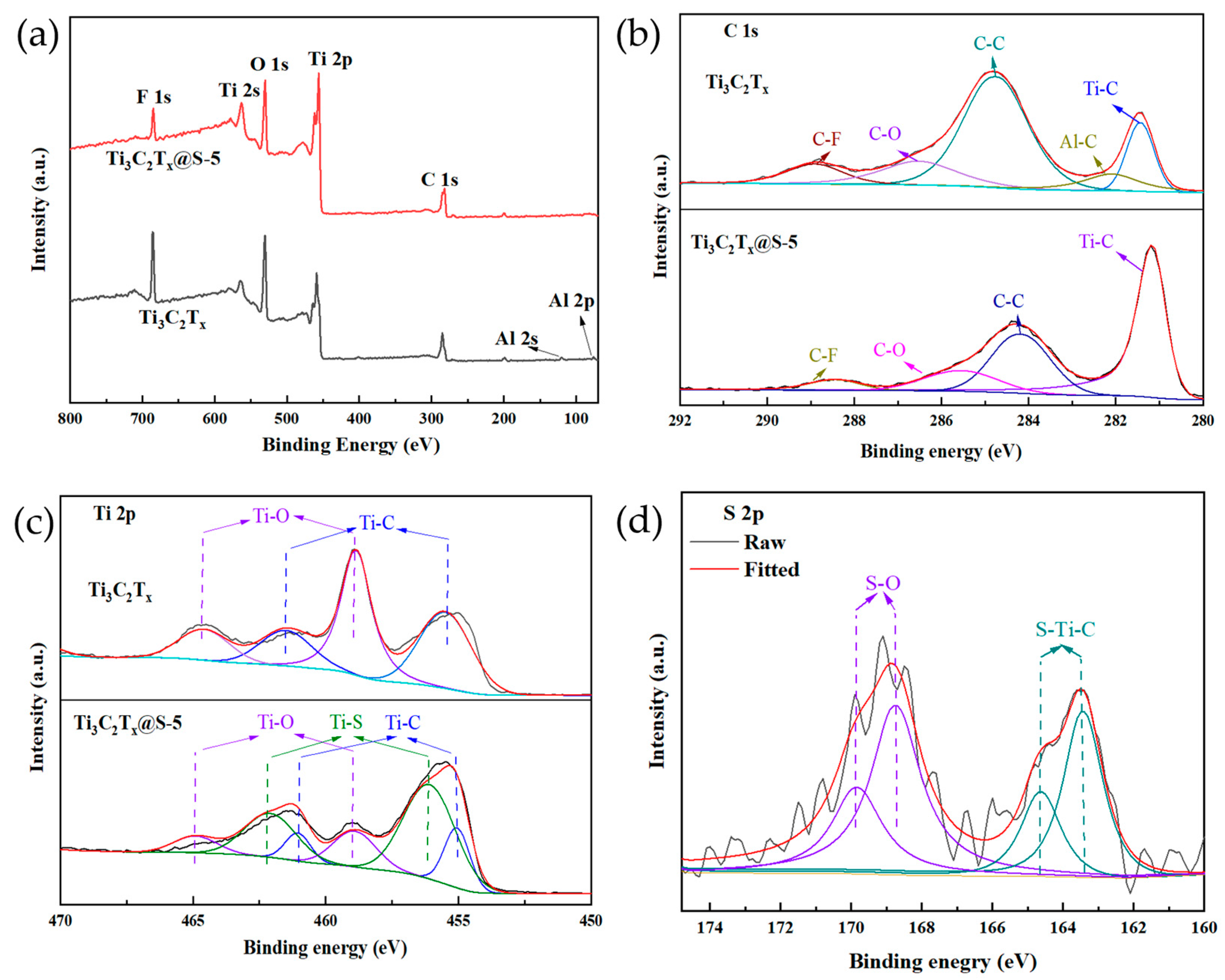
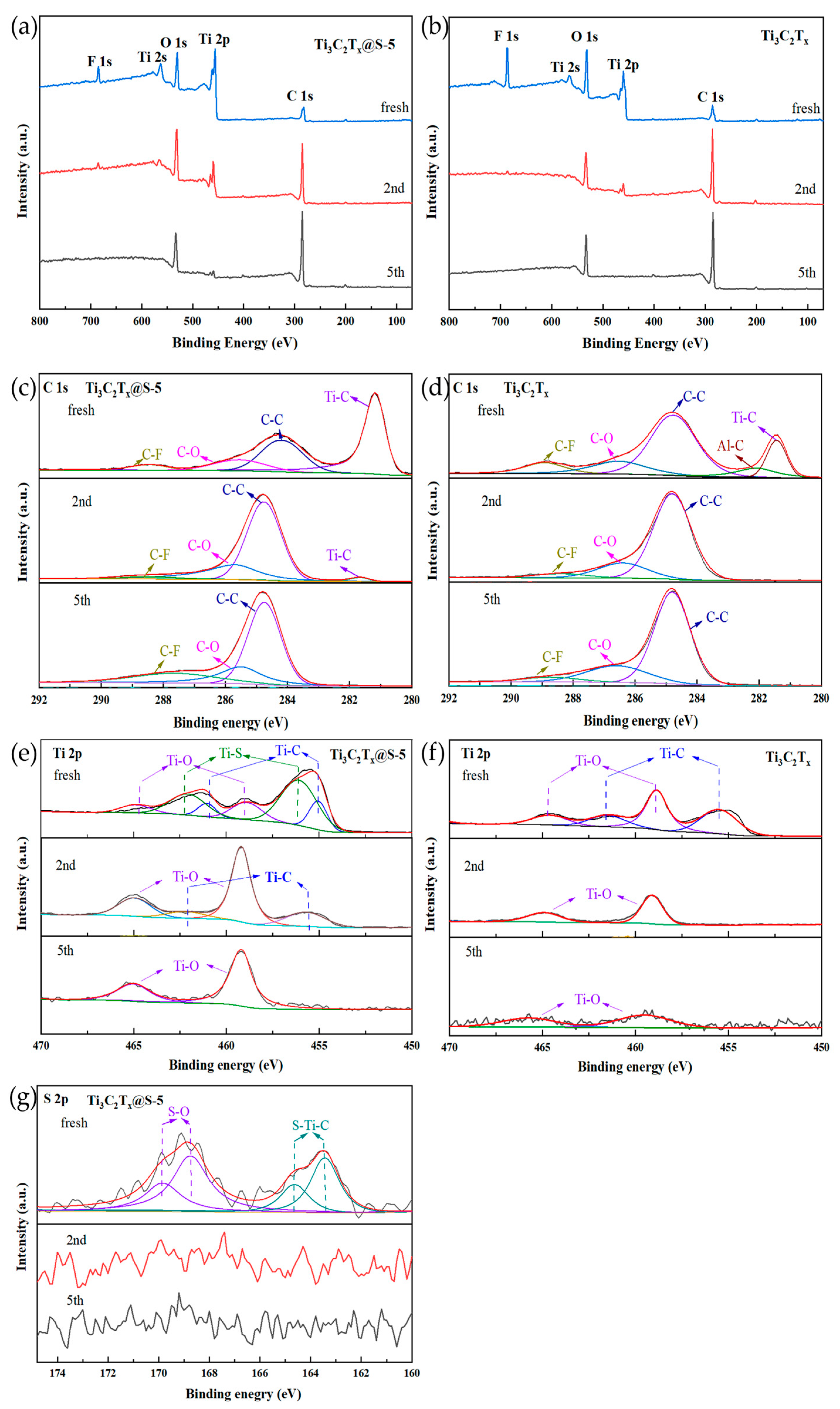
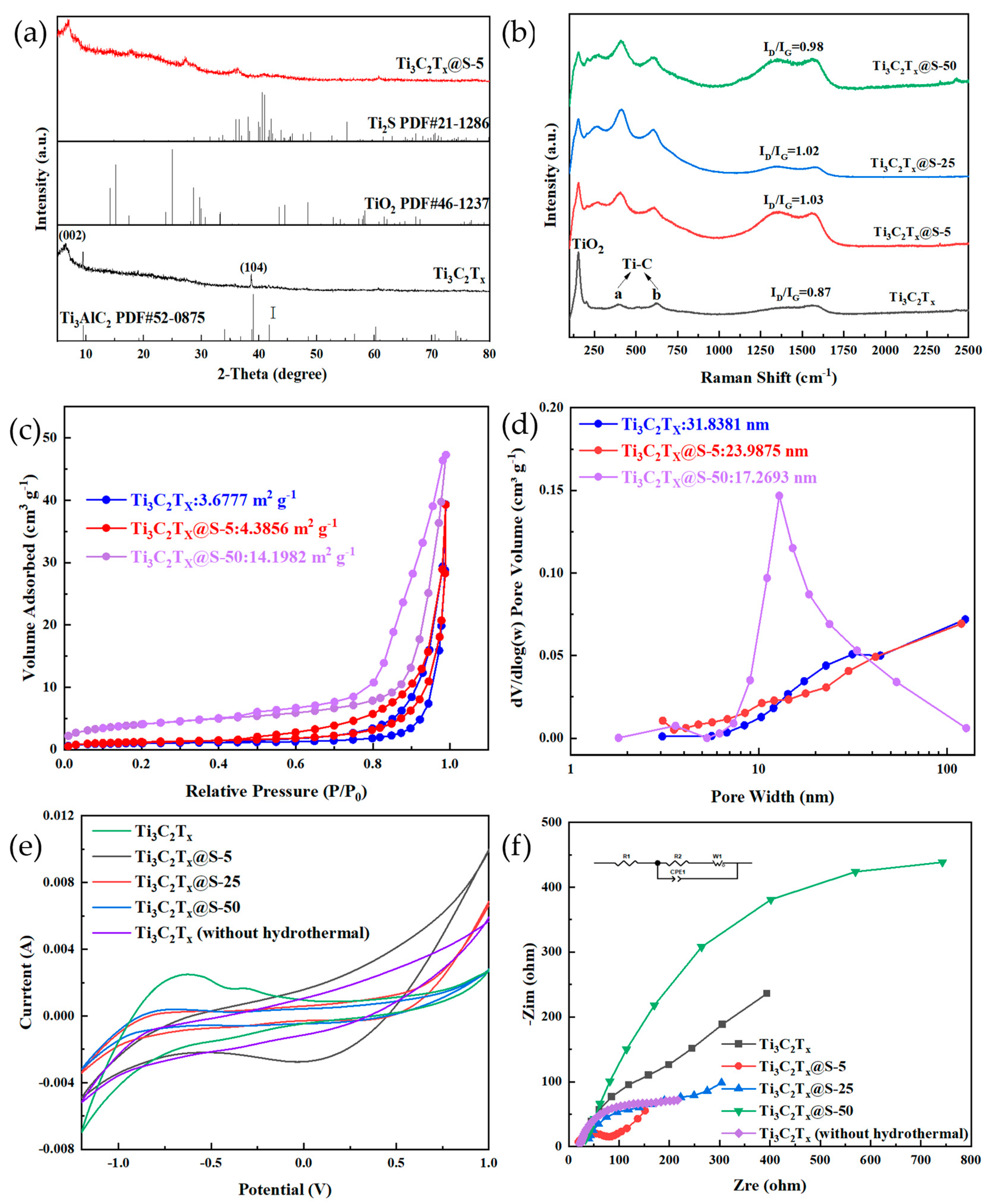
2.1. Characterization Results

The literature states that the typical peaks of Ti3AlC2 include the (002), (004), (101), (104), (105), (109), and (110) planes at 9.5°, 19.1°, 33.9°, 38.8°, 41.6°, 56.0°, and 60.6°, respectively [10]. Figure 1a shows that after the corrosion of Al layers, Ti3C2Tx presented a dramatic leftward shift to 6.5° and the broadening of the (002) plane, implying that the Ti3C2Tx structure became distorted with Al etching. The Bragg equation [11] showed that the layer spacing of Ti3C2Tx was 1.36 nm, which was greater than Ti3AlC2 (0.93 nm). This result further proved that the etching of Al layers induced the expansion of layer spacing. However, the persistence of the characteristic peak (104) of the Al plane indicated that residual Al was present. The Al layers were further etched after modification with S, as proven by the reduction in the (104) Al plane. The slight rightward shift of the (002) peak from 6.5° to 6.9° indicated the differentiation of lattice structure between Ti3C2Tx and Ti3C2Tx@S–5. Compared with Ti3C2Tx, Ti3C2Tx@S–5 presented more obvious peaks at 17.8° and 27.3°. These peaks were related to the transformation of Ti3C2Tx into TiO2 [12]. The smaller layer spacing (1.28 nm) of Ti3C2Tx@S–5 than Ti3C2Tx suggested that S elements had been introduced between layers. As indices of Ti2S, the small peaks at 36.4° and 41.0° further proved the successful S modification of Ti3C2Tx [13].
The defects in the materials caused by S doping were analyzed by using Raman spectra with a wavelength of 523 nm and a power of 75 mW. The results are presented in Figure 1b. Notably, Ti3C2Tx retained obvious characteristic a and b peaks after etching, indicating that C–Ti bonds [14] were retained, whereas the Al element was etched away. After S modification, the characteristic a and b peaks intensified and became increasingly obvious. The changes in the strengths of the a and b peaks indirectly proved the etching of Al layers and the decrease in terminal functional groups (–F and –OH). Meanwhile, the peak intensity, at approximately 153 cm−1, belonged to Ti3C2Tx MXene oxidation and the formation of the TiO2 [15]. The two broad peaks at 1350 and 1580 cm−1 were assigned to the D and G bands of graphitic carbon, respectively. The intensity ratio between the D–peak and G–peak (ID/IG) can reflect the degree of the defects and graphitization of carbon materials [16]. The ID/IG values of Ti3C2Tx, Ti3C2Tx@S–5, Ti3C2Tx@S–25, and Ti3C2Tx@S–50 were 0.87, 1.03, 1.02, and 0.98, respectively. The ID/IG ratio of Ti3C2Tx@S–5 was larger than pure Ti3C2Tx. The doping of S atoms created additional defects in Ti3C2Tx, resulting in the creation of additional active sites and conductive carbide for rapid charge transfer [17]. However, as the doping amount of S further increased, the ID/IG ratios of the materials reduced, likely due to the stacking of S on the surface of Ti3C2Tx [18]. To further determine this, the nitrogen adsorption–desorption isotherms (Figure 1c) of Ti3C2Tx, Ti3C2Tx@S–5, and Ti3C2Tx@S–50 were tested, and the pore size distribution (Figure 1d) was calculated from N2 desorption isothermals. It was found that the BET surface area increases while the pore size decreases with an increase in S doping, suggesting that Ti3C2Tx@S–5 can exhibit a larger contact area, presenting a better performance than Ti3C2Tx. However, the excessive S (Ti3C2Tx@S–50) led to the collapse of the Ti3C2Tx, which exhibits a much larger BET surface area and reduced pore size, resulting in fewer channels capable and active sites of performing the reaction, which causes a deterioration of the performance. Therefore, it is believed that the high performance of Ti3C2Tx@S–5 is due to the optimal doping of S.
CV and EIS were conducted to investigate the conductivity of the materials further. The results are shown in Figure 1c,d. Ti3C2Tx@S–5 presented the largest CV area and the highest peak current among all materials, indicating that the redox and electron transfer capability of Ti3C2Tx@S–5 was superior to Ti3C2Tx [19]. EIS was further performed to analyze the electron conductivity of the composite materials, as shown in Figure 1d. The Nyquist plots consisted of half arcs in the high–frequency region, which represent the diffusion and migration of ions inside the electrode. A small radius in the high–frequency region is indicative of low charge transfer resistance. The fitting results of the low–frequency region were in a straight line, which reflected internal resistance from the electrolyte and electrode [20]. Ti3C2Tx@S–5 had the smallest arc radius among the test materials, further demonstrating its excellent internal resistance [21]. However, extensive S introduction could result in the coverage of conductive carbide for rapid charge transfer, causing a decrease in the arc radii of Ti3C2Tx@S–25 and Ti3C2Tx@S–50. All of the above CV and EIS results suggested that the redox electron transfer capability of Ti3C2Tx@S–5 was superior to the other materials.
The morphologies of Ti3C2Tx and Ti3C2Tx@S–5 were compared to observe the introduction of S in further detail. Figure 2a,b depict the typical SEM images of the Ti3C2Tx and Ti3C2Tx@S–5 composites, which all exhibited multilayered structures. In Figure 2a, Ti3C2Tx presented stacked layers and a fragmented structure. However, with S modification, the separated layer structure of Ti3C2Tx@S–5 became highly obvious, and the agglomeration of Ti3C2Tx was significantly inhibited. Thinner and more obvious layers [22] of Ti3C2Tx@S–5 were obtained. The TEM image of Ti3C2Tx (Figure 2c) presented a clear layered structure with fuzzy edges. By contrast, Ti3C2Tx@S–5 appeared as an ultrathin sheet without wrinkles (Figure 2d) and exhibited a larger interlayer spacing of 1.02 nm [23] after S doping than typical Ti3C2Tx (0.98 nm). The thin and distinctly layered structure of Ti3C2Tx@S–5 confirmed that Al was further etched via S modification, and the expansion of interlayer spacing proved that S had been successfully introduced into Ti3C2Tx. The EDS mapping in Figure 2e shows that the Ti, Cl, Al, F, and S elements had been uniformly distributed throughout the Ti3C2Tx@S–5 composite, as reflected by the specific data provided (Figure 2f), in which a distribution chart of the total spectrum atomic percentage of Ti3C2Tx and Ti3C2Tx@S–5 is shown in Table 1. The content of F and Al elements decreased from 49.44% and 4.68% to 30.90% and 1.94%, respectively, while S increased from 0% to 0.99% with the introduction of S, indicating the successful synthesis of Ti3C2Tx@S–5 with an S content of 0.99%.
The materials were subjected to XPS to characterize the changes in elements and chemical bonds in Ti3C2Tx with or without S modification. The peaks at 280, 565, 456, 530, and 684 eV in the survey of the XPS spectra of Ti3C2Tx and Ti3C2Tx@S–5 (Figure 3a) corresponded to C 1s, Ti 2s, Ti 2p, O 1s, and F 1s, respectively. The weaker response of the Al element in Ti3C2Tx@S–5 than Ti3C2Tx confirmed that Al had been replaced with S and was consistent with the XRD results. The response of F and O was attributed to the terminal edge groups of –F and –OH. However, the response of S in Ti3C2Tx@S–5 was unobservable because of the low loading amount of S. The Ti 2p, C 1s, and S 2p spectra were discussed to obtain additional details on S modification. C–C (284.8 eV), C–Ti (281.4 eV), C–O (286.5 eV), C–Al (282.1 eV), and C–F (288.9 eV) were clearly observed [24] in the high–resolution C 1s spectra (Figure 3b) of Ti3C2Tx, whereas the C–Al bond diminished in Ti3C2Tx@S–5. This result was also proven by XRD. Furthermore, the obvious shifts of the C–C, C–Ti, C–O, and C–F bonds to 284.2, 281.2, 285.6, and 288.4 eV, respectively, indicated that the lattice structure had been modified via S introduction. In addition, the downshifting of the C 1s spectra demonstrated that the proper modification of S was beneficial to attracting free electrons in C [25].
Figure 3c shows the high–resolution Ti 2p spectra of Ti3C2Tx. The Ti–O and Ti–C bonds were located at the binding energies of 464.8/458.9 and 461.5/455.5 eV, respectively. The Ti–O and Ti–C bonds had slightly shifted to 464.9/459.0 and 461.0/455.0 eV after S modification, respectively. Furthermore, the appearance of a new Ti–S bond at 462.2 and 456.2 eV confirmed the introduction of S. In the S 2p XPS spectra of Ti3C2Tx@S–5 (Figure 3d), S–O and S–Ti–C bonds [26] were observed at 169.8/168.7 and 164.6/163.5 eV, respectively, further validating the XRD results and Ti 2p spectra. Based on the XPS results, S was predicted to react with the exposed Ti sites of Ti3C2Tx and form Ti–S bonds, inducing the replacement of some functional groups (–OH and –F) on the surface of Ti3C2Tx by –S [27]. The Ti–S bond played a supporting role in maintaining the original structure of Ti3C2Tx and prevented the superposition of layers between materials.

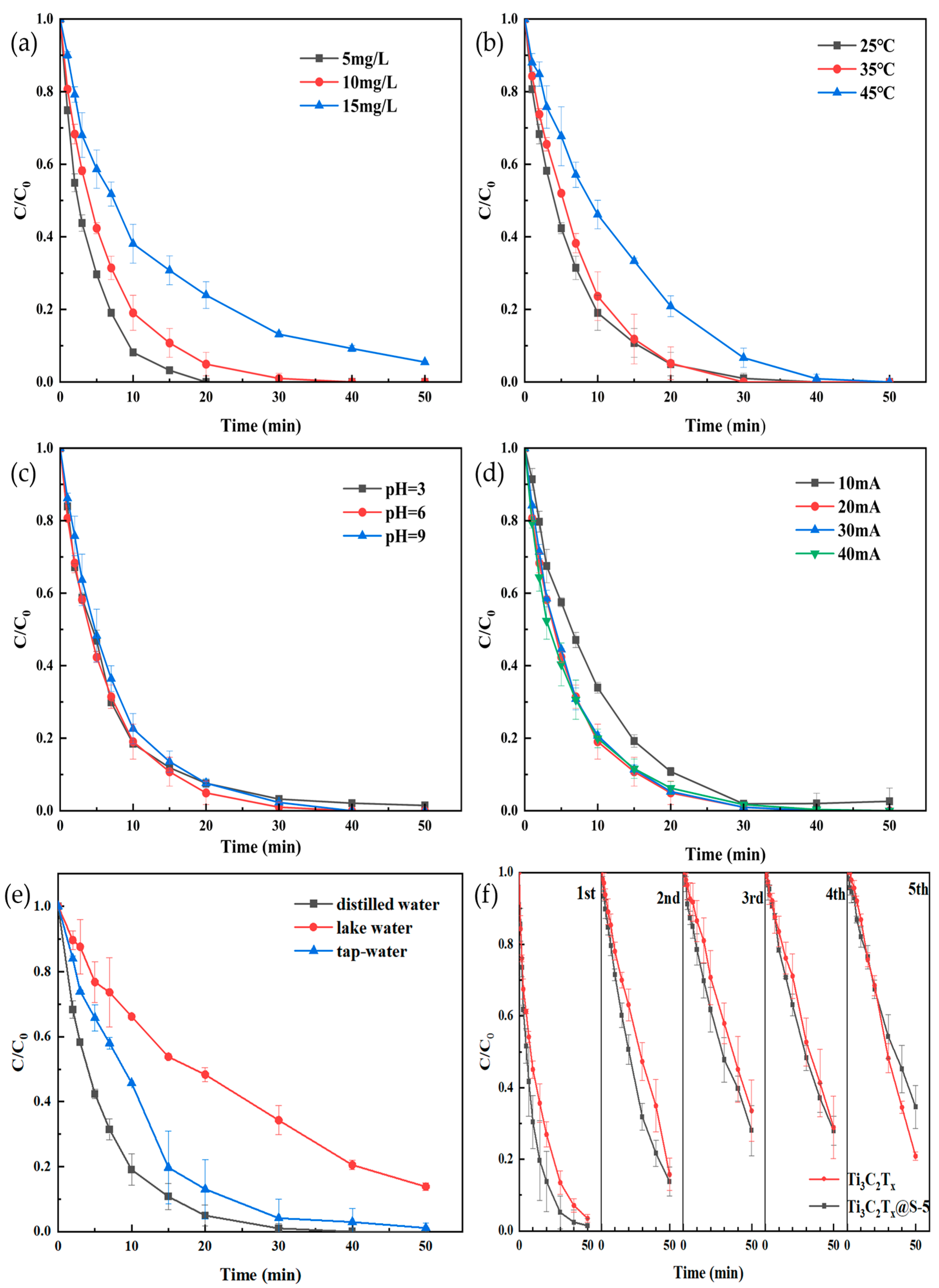
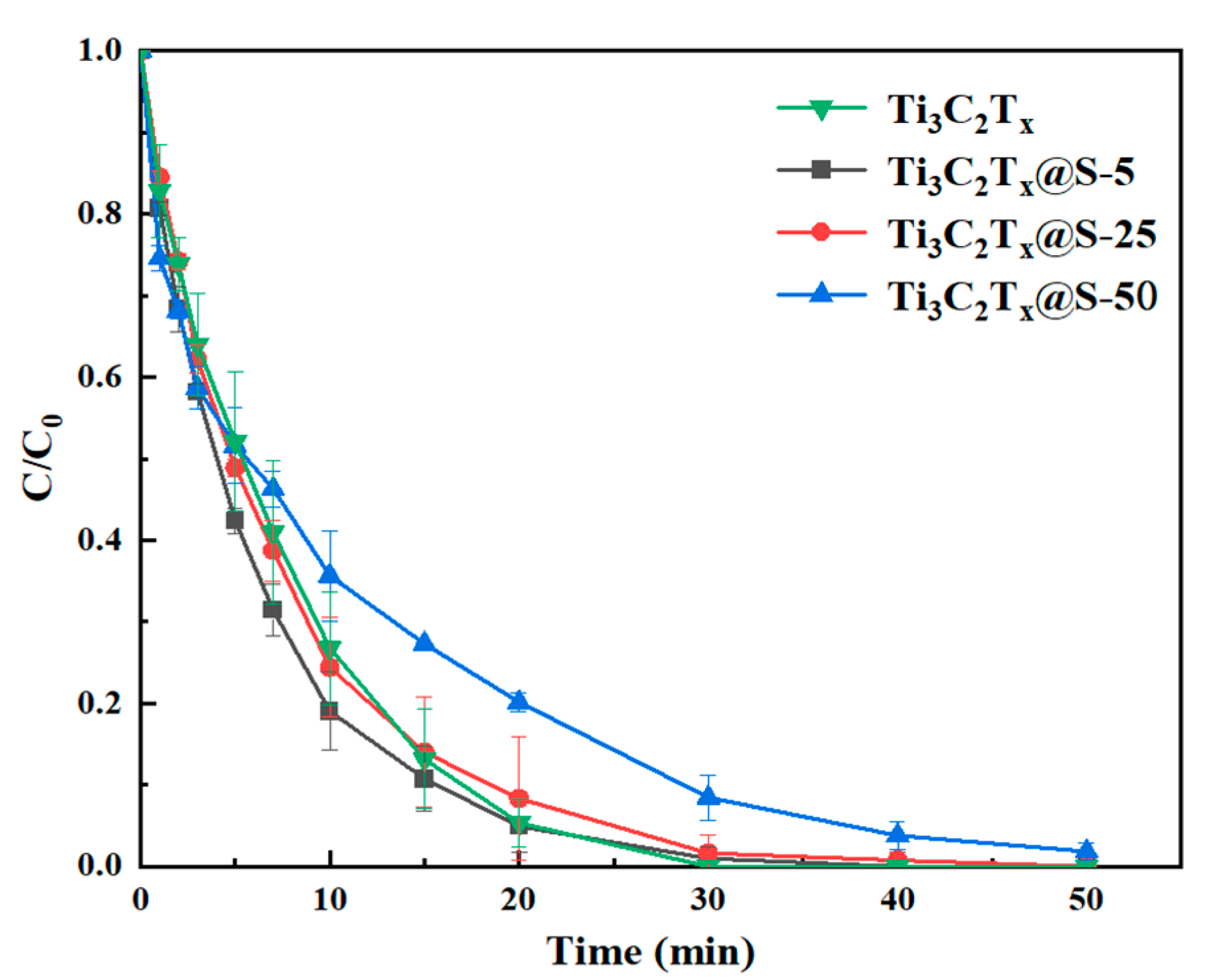
2.2. Catalytic Capacity

TC electrocatalytic degradation experiments were conducted with Ti3C2Tx, Ti3C2Tx@S–5, Ti3C2Tx@S–25, and Ti3C2Tx@S–50 to demonstrate the function of S groups. Figure 4 shows that after S modification, TC degradation by Ti3C2Tx@S–5 had significantly improved compared with Ti3C2Tx. This result confirmed the positive contribution of the Ti–S bond to the degradation of TC. After appropriate S modification, Ti3C2Tx@S–5 accelerated electron transfer. This effect was conducive to the improvement in catalytic capacity [28]. However, with extensive S loading, the remaining S covered the surface of Ti3C2Tx, resulting in a significant decrease in Ti3C2Tx@S–50. In other words, excessive S and its uneven distribution hindered TC degradation. This phenomenon was consistent with the CV and EIS results (Figure 1c,d). Therefore, for subsequent experiments on degradation efficiency, Ti3C2Tx@S–5 was selected, and the most suitable environmental impact parameters were identified to evaluate the stability and performance of Ti3C2Tx@S–5 in TC degradation under various conditions.
The effects of initial concentration, pH, temperature, applied current, and different water bodies were discussed to expand the practical application of the tested materials in the electrocatalytic degradation of TC. TC, with an initial concentration of 5 mg L−1, was completely removed within 20 min (Figure 5a). TC removal efficiency reached 100% and 94.5% at the initial TC concentrations of 10 and 15 mg L−1, respectively. TC degradation efficiency decreased with an increase in temperature due to active chlorine production (Figure 5b). During degradation, Cl was directly oxidized to generate soluble Cl2 (aq) (Equation (1)), which can be quickly hydrolyzed into hypochlorous acid (HClO) (Equation (2)). In addition, hypochlorite was unstable and decomposed into hypochlorite ions (ClO) (Equation (3)). The electrode potentials of the three types of chlorine were ranked in descending order as Cl2 (aq) (1.36 V) > HClO (1.49 V) > ClO (0.89 V) [29]. TC degradation was significantly promoted by the strongly oxidizing Cl2 (aq) and HClO but was weakly promoted by ClO. Degradation efficiency decreased when the electrolysis temperature exceeded 25 °C due to the significant decrease in the solubility of Cl2 (aq) with the increase in temperature. Most Cl2 escaped in the form of gas [30].
2 C l   C l 2 a q + 2 e
C l 2 a q + H 2 O   H C l O + C l + H +
H C l O   C l O + H +
Figure 5c shows the influence of initial pH on TC degradation. The final TC removal efficiency of Ti3C2Tx@S–5 changed slightly with the change in pH. Approximately 100% degradation was obtained at pH 3–9, indicating the applicability of Ti3C2Tx@S–5 under acidic and alkaline conditions [31]. When the current was adjusted from 10 mA to 20 mA (Figure 5d), the degradation efficiency of TC increased from 97.4% to 100%. The increase in applied current initially promoted degradation efficiency. Figure 5d illustrates that as the applied current increased, the electron transfer rate increased [32]. The degradation efficiency remained stable (100%) when the applied current was further increased to 30 and 40 mA because the equilibrium between the anode side reaction [33] and reactive species generation under high current maintained the stability of degradation. The efficiencies of TC degradation in various water bodies are reflected in Figure 5e. The efficiencies of TC degradation in distilled water, tap water, and lake water reached 100%, 98.9%, and 86.2%, respectively, within 50 min. The acceptable efficiency exceeded 85%, indicating that Ti3C2Tx@S–5 has broad application prospects for TC degradation in actual water bodies. Long–term stability was further estimated, as illustrated in Figure 5f. Cycle tests on the TC system showed that its efficiency was reduced by 20% after the second experiment. Slight differences were observed in the next three cycles. The reduction in catalytic performance after repeated use may be due to the loss of S from the Ti–S bond in Ti3C2Tx@S–5.
Ti3C2Tx@S–5 and Ti3C2Tx before and after the reaction were analyzed via XPS to clarify their mechanism during cycling. As the number of cycles increased, the peaks of F 1s, Ti 2s, and Ti 2p significantly decreased, whereas C 1s drastically increased (Figure 6a,b). Ti 2p, C 1s, and S 2p spectra were further discussed to clarify these changes. The C 1s spectra results show that Ti3C2Tx@S–5 still had a Ti–C bond (Figure 6c) compared to Ti3C2Tx (Figure 6d) in the second cycle, indicating that the layered supporting effect of the Ti–C bond may enhance the degradation of TC, while Ti3C2Tx had already lost the Ti–C bond by the second cycle, which further explained that the degradation efficiency of Ti3C2Tx@S–5 remained higher than Ti3C2Tx after the second cycle. However, the Ti–C bond disappeared from the C 1s spectrum at the fifth cycle, illustrating the disconnection of the Ti–C bond in the layered structure during degradation. This phenomenon was also confirmed based on the Ti 2p spectra of Ti3C2Tx@S–5 (Figure 6e) and Ti3C2Tx (Figure 6f). Furthermore, after the second reaction, S species decreased, as reflected in the Ti 2p (Figure 6e) and S 2p spectra (Figure 6g). This finding was consistent with the reduction in degradation efficiency observed after the second cycle and also implied the positive and crucial function of S groups in Ti3C2Tx@S–5.
To further demonstrate the high efficiency of Ti3C2Tx@S–5 in degrading TC, Ti3C2Tx@S–5 and other types of catalysts were compared and shown in Table 2. It can be seen that the Ti3C2Tx@S–5 material can achieve 100% degradation efficiency in a shorter time without adjusting the pH in advance, indicating that Ti3C2Tx@S–5 has broad application prospects for TC degradation.

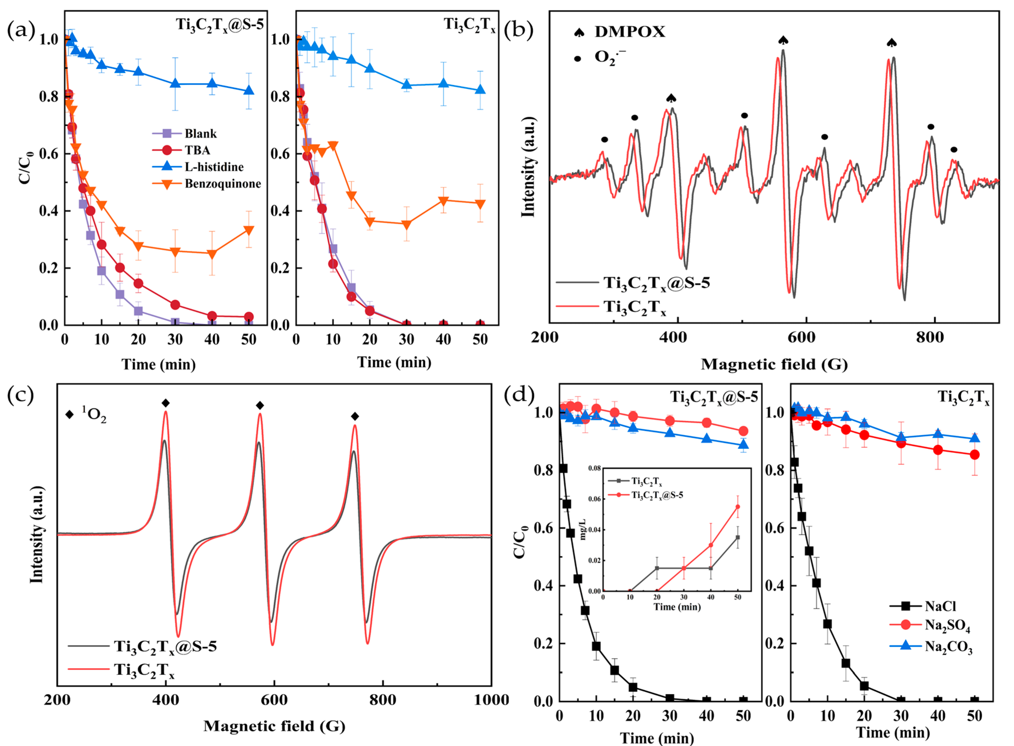
2.3. Active Substance Determination

Quenching experiments were conducted, as shown in Figure 7a, to identify the radicals participating in TC degradation triggered by Ti3C2Tx and Ti3C2Tx@S–5. TBA, benzoquinone, and L–histidine were used as free radical scavengers of ·OH, ·O2, and 1O2, respectively [41,42,43]. The results in Figure 7a illustrate that negligible removal efficiencies were observed in the Ti3C2Tx and Ti3C2Tx@S–5 systems under interference by benzoquinone and L–histidine. This finding revealed that ·O2 and 1O2 had dominant contributions as main active substances. By contrast, the Ti3C2Tx@S–5 system retained approximately 97.0% TC removal efficiency in the presence of TBA, whereas TBA had a negligible inhibitory effect in the Ti3C2Tx system. This result indirectly proved the positive contribution of S groups to ·OH generation. The generation of additional ·OH with the introduction of S increased TC removal by approximately 3.0%. Furthermore, the quenching results were confirmed by EPR measurements with DMPO as a spin–trapping reagent of ·OH and ·O2 and TEMPO as a spin–trapping reagent of 1O2 [44,45]. Figure 7b shows that typical sextet peaks [46] of ·O2 with similar intensities were presented by the Ti3C2Tx and Ti3C2Tx@S–5 systems, demonstrating the close contribution of ·O2 in the Ti3C2Tx and Ti3C2Tx@S–5 systems. However, the weak response of ·OH was covered by ·O2 and DMPOX signals [47]. In addition, the presence of the typical triple peaks [48] of 1O2 with similar intensities confirmed that 1O2 was generated from Ti3C2Tx and Ti3C2Tx@S–5 (Figure 7c). All above quenching and EPR observations demonstrated that ·O2 and 1O2 were produced and were the dominant radicals of TC degradation. These findings, combined with the characterization results of Ti3C2Tx and Ti3C2Tx@S–5, indicated that the existence of ·O2 and 1O2 was induced by the Ti3C2Tx substrate. S groups contributed small amounts of ·OH.
The active species produced from the electrolyte were also taken into account to provide full information on the active species involved in the reaction. The TC removal efficiency in the presence of 1 g L−1 Na2CO3, Na2SO4, and NaCl electrolytes was examined. Figure 7d shows that within 40 min, the TC removal efficiency reached 100% in the presence of the NaCl electrolyte and reached only approximately 10% within 50 min in the presence of Na2CO3 and Na2SO4 electrolytes. The superior influence of NaCl on TC removal suggested the generation of secondary active chlorine (such as ClO) from Cl (Equations (1)–(3)) [49]. The quantitative analysis of active chlorine is presented in Figure 7d. Compared with Ti3C2Tx, Ti3C2Tx@S–5 consumed active chlorine within 30 min at a faster rate. In addition, the accumulation of active chlorine in the Ti3C2Tx@S–5 system was higher than the Ti3C2Tx system. These results show that active chlorine is an active species involved in the electrocatalytic degradation of TC [50], and Ti3C2Tx@S–5 produces more active chlorine than Ti3C2Tx.

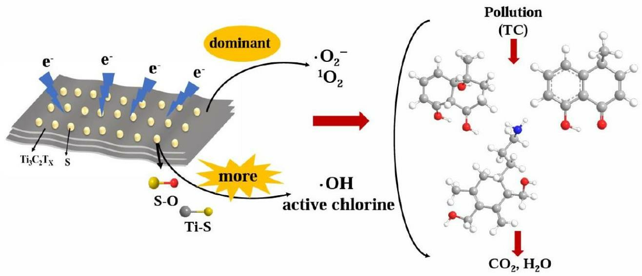
2.4. Identification of the Degradation Pathway

The main degradation intermediates were analyzed by LC–MS to identify the specific pathway of the electrocatalytic degradation of TC by Ti3C2Tx@S–5. Their detailed data are included in the Supplementary Materials, and the possible pathways of TC degradation are shown in Figure 8.
TC was easily attacked by ·OH, ·O2, 1O2, and active chlorine due to its three high–electron–density functional groups, namely double bonds, phenolic groups, and amino groups [51]. After the TC molecule was attacked by free radicals, the amide end group was removed, and demethylation and dehydration occurred simultaneously, generating intermediates P1 and P5 (m/z = 370 and 382). P2 (m/z = 303) was produced by P1 through dehydration. The central carbon chain of P2 was continuously broken to yield intermediates P3 and P4 (m/z = 193 and 173). Finally, P2 was degraded into inorganic compound compounds, such as CO2 and H2O [52,53,54]. In the other path, ·OH can attack the ortho or para position of the phenol ring [55] in P5 (m/z = 382), and demethylation occurred to yield the intermediate P6 (m/z = 278). Subsequently, P7 (m/z = 224) was obtained through simple reactions (ring opening and hydroxyl removal) and ultimately degraded into CO2 and H2O.

3. Experimental

3.1. Reagents and Materials

Carbon titanium aluminum (Ti3AlC2), tetracycline hydrochloride (TC, 96%), lithium fluoride (LiF), and dibasic potassium phosphate (K2HPO4, purity > 99%) for high–performance liquid chromatography (HPLC) were brought from Shanghai Macklin Biochemical Technology Co., Ltd. (Shanghai, China) Hydrochloric acid (HCl), sodium hydroxide (NaOH), benzenehexathiol (C6S6H6), sodium chloride (NaCl), sodium sulfate (Na2SO4), sodium thiosulfate (Na2S2O3), ethanol (C2H5OH), methanol (CH3OH), acetonitrile (C2H3N), tert–butyl alcohol (TBA), L–histidine (C6H9N3O2), and benzoquinone (BQ) were purchased from Shantou Xilong Scientific Co., Ltd. (Shantou, China).

3.2. Material Synthesis

3.2.1. Synthesis of Ti3C2Tx MXene without Hydrothermal Nanosheets

Ti3C2Tx was fabricated by acid–etching Al with Ti3AlC2 as the raw material. LiF (1.0 g) was added to HCl (9 mol L−1, 40 mL), and the resulting mixture was stirred for 30 min. The mixture was stirred, added to Ti3AlC2 MAX powder gradually, and magnetically agitated at 45 °C for 24 h. The obtained mixture was washed with distilled water and centrifuged until the resulting supernatant had a pH of 6.0. Ti3C2Tx MXene powder without hydrothermal was obtained by filtering and drying the product.

3.2.2. Synthesis of Ti3C2Tx@S Nanosheets

The Ti3C2Tx@S complex was synthesized by the hydrothermal method. Ti3C2Tx MXene powder was added to distilled water and subjected to ultrasonic treatment for 1 h under nitrogen. A total of 0, 5, 25, or 50 mg of C6S6H6 was dissolved in C2H5OH and mixed with the Ti3C2Tx MXene suspension under ultrasonication for 3 h under nitrogen. The mixture was placed in an autoclave and reacted at 180 °C for 2 h. Subsequently, the mixture was centrifuged at 1000 rpm for 3 min. The supernatant was then collected and further centrifuged at 3500 rpm for 15 min. The product was filtered and dried to obtain Ti3C2Tx, Ti3C2Tx@S–5, Ti3C2Tx@S–25, and Ti3C2Tx@S–50 nanosheets.

3.3. Characterization

Field–emission scanning electron microscopy (SEM, Regulus 8100) and transmission electron microscopy (TEM, Tecnai–G2–F30) combined with energy–dispersive X-ray spectroscopy (EDS) were used to examine the surface morphologies of Ti3C2Tx and Ti3C2Tx@S. The etching of the catalyst structure was recorded with XRD (D8 Advance) by using Cu Kα radiation. Raman spectra (Renishaw in Via) were applied to characterize the degree of defects in the catalysts. Electrical conductivity was measured by cyclic voltammetry (CV) and electrochemical impedance spectroscopy (EIS) on electrochemical stations (CHI660E, Chen Hua) with a standard three–electrode cell (with a Pt plate, Ag/AgCl electrode, and carbon rod). Chemical bonds in the catalyst were detected by X-ray photoelectron spectroscopy (XPS, Thermo ESCALAB 250X, Waltham, MA, USA).

3.4. Catalytic Experiment and Analyses

The electrocatalytic experiment used three electrodes: the catalyst as the anode, copper as the cathode, and Ag/AgCl as the reference electrode. The distance between the cathode and anode was 1 cm. A 2 cm × 2 cm carbon cloth with the catalyst was placed in a 60 °C oven for 30 min, and a conductive adhesive was used as the adhesive. The electrolyte was 10 mg L−1 TC and contained 1 g L−1 NaCl. Direct current power was supplied by a PS–12 constant–current rectifier (Eurasian ZTE Technology, Beijing, China). Parallel experiments were conducted to ensure the accuracy of the data of the electrocatalytic experiments.
When the three electrodes were electrified, 2 mL from the 200 mL reaction solution was collected at a certain time point (0, 1, 2, 3, 5, 7, 10, 15, 20, 30, 40, and 50 min), mixed with a quenching agent (50 μL of Na2S2O3), and then loaded into a liquid–phase bottle through a 0.22 μL filter. TC concentration was measured via HPLC (Waters ACQUITY Arc–2695) by using a 2998PDA detector. The reaction conditions were as follows: a mobile phase of 25% C2H3N and 75% K2HPO4; a C18 column (Waters COR–TECS); a column temperature of 25 °C; a flow rate of 1 mL min−1; and a peak time of within 4 min. C/C0 was used to represent the degree of TC degradation, whereas C and C0 represent the concentration at a certain time and the initial concentration, respectively.
Electron paramagnetic resonance (EPR, Bruker EMX–10/12) was used to detect and analyze free radicals with 10 mmol L−1 5,5–dimethyl–1–pyrrolidine–N–oxide (DMPO) as the ·OH and ·O2 trapping agent and 2,2,6,6–tetramethyl–4–piperidol (TEMPO) as the 1O2 trapping agent. Meanwhile, the quenching experiment was performed to identify active free radicals by adding benzoquinone, L–histidine, and TBA. The concentration of active chlorine at different time points was determined by N, N–diethyl–1,4–phenylenediamine spectrophotometry.
Liquid chromatography–mass spectrometry (LC–MS, Shimadzu) was used to analyze the intermediate degradation products. The pretreatment process of the experiment was the same as the electrocatalytic experiments and had the following specific conditions: a mobile phase of 65% CH3OH and 35% deionized water; a negative ion scanning mode; an XDB–C18 column (2.1 mm × 150 mm, 5 μm); a column temperature of 30 °C; and a flow rate controlled to 1 mL min−1.

4. Conclusions

In this research, S–doped MXene for the electrocatalytic oxidation degradation of TC was successfully prepared with the hydrothermal method. The electron transfer efficiency and surface activity of Ti3C2Tx@S–5 improved with the formation of S–O and Ti–S bonds. The Ti3C2Tx@S–5 catalyst achieved 100% degradation efficiency within 50 min under the conditions of 25 °C, pH 6, 10 mg L−1 TC, and 20 mA, and maintained approximately 80% of its degradation efficiency after five cycles. ·OH, ·O2, 1O2, and active chlorine were identified as the main species involved in electrocatalysis. The introduction of S resulted in the positive promotion of ·OH and active chlorine generation. The degradation pathways identified by HPLC–MS analysis further demonstrated the contribution of ·OH, ·O2, 1O2, and active chlorine to TC treatment.

Supplementary Materials

The following supporting information can be downloaded at: https://www.mdpi.com/article/10.3390/catal13091237/s1, Figure S1. (a–g) Detailed data graph of TC degradation by-products; Table S1. The proposed transformation products of TC.

Author Contributions

Conceptualization, F.Z., Q.Z. and C.-T.C.; methodology, F.Z.; software, F.Z. and Y.-Y.L.; validation, Q.Z. and C.-T.C.; formal analysis, F.Z.; investigation, F.Z., Z.H. and Y.-Y.L.; resources, Q.Z.; data curation, Z.H.; writing—original draft preparation, F.Z.; writing—review and editing, F.Z. and Q.Z.; visualization, Q.Z.; supervision, Q.Z.; project administration, Q.Z. and C.-T.C.; funding acquisition, Q.Z. All authors have read and agreed to the published version of the manuscript.

Funding

This work was financially supported by the Natural Science Foundation of China under grant 51978291, the Fujian Province Science and Technology Project Foundation (2021J01311, 2022I0030), and the Xiamen Science and Technology Project Foundation (3502Z20226012).

Data Availability Statement

Not available.

Acknowledgments

The authors would like to acknowledge the Testing Center of Huaqiao University for the TEM and LC–MS.

Conflicts of Interest

The authors declare no conflict of interest.

References

  1. Cheng, M.; Zeng, G.M.; Huang, D.L.; Lai, C.; Xu, P.; Zhang, C.; Liu, Y. Hydroxyl radicals based advanced oxidation processes (AOPs) for remediation of soils contaminated with organic compounds: A review. Chem. Eng. J. 2016, 284, 582–598. [Google Scholar] [CrossRef]
  2. Wei, C.L.; Tao, Y.; An, Y.L.; Tian, Y.; Zhang, Y.C.; Feng, J.K.; Qian, Y.T. Recent Advances of Emerging 2D MXene for Stable and Dendrite-Free Metal Anodes. Adv. Funct. Mater. 2020, 30, 2004613. [Google Scholar] [CrossRef]
  3. Liu, H.J.; Dong, B. Recent advances and prospects of MXene-based materials for electrocatalysis and energy storage. Mater. Today Phys. 2021, 20, 100469. [Google Scholar] [CrossRef]
  4. Naguib, M.; Mochalin, V.N.; Barsoum, M.W.; Gogotsi, Y. 25th Anniversary Article: MXenes: A New Family of Two-Dimensional Materials. Adv. Mater. 2014, 26, 992–1005. [Google Scholar] [CrossRef]
  5. Morales-Garcia, A.; Calle-Vallejo, F.; Illas, F. MXenes: New Horizons in Catalysis. ACS Catal. 2020, 10, 13487–13503. [Google Scholar] [CrossRef]
  6. Cao, F.C.; Zhang, Y.; Wang, H.Q.; Khan, K.; Tareen, A.K.; Qian, W.J.; Zhang, H.; Agren, H. Recent Advances in Oxidation Stable Chemistry of 2D MXenes. Adv. Mater. 2022, 34, 29. [Google Scholar] [CrossRef]
  7. Tang, Q.; Zhou, Z.; Shen, P.W. Are MXenes Promising Anode Materials for Li Ion Batteries? Computational Studies on Electronic Properties and Li Storage Capability of Ti3C2 and Ti3C2X2 (X = F, OH) Monolayer. J. Am. Chem. Soc. 2012, 134, 16909–16916. [Google Scholar] [CrossRef]
  8. Zheng, X.; Wang, Z.L.; Li, J.J.; Wei, L.M. Binder-free S@Ti3C2Tx sandwich structure film as a high-capacity cathode for a stable aluminum-sulfur battery. Sci. China-Mater. 2022, 65, 1463–1475. [Google Scholar] [CrossRef]
  9. Zhao, X.Q.; Liu, M.; Chen, Y.; Hou, B.; Zhang, N.; Chen, B.B.; Yang, N.; Chen, K.; Li, J.L.; An, L.A. Fabrication of layered Ti3C2 with an accordion-like structure as a potential cathode material for high performance lithium-sulfur batteries. J. Mater. Chem. A 2015, 3, 7870–7876. [Google Scholar] [CrossRef]
  10. Zhang, F.; Zhou, Y.; Zhang, Y.; Li, D.C.; Huang, Z.C. Facile synthesis of sulfur@titanium carbide Mxene as high performance cathode for lithium-sulfur batteries. Nanophotonics 2020, 9, 2025–2032. [Google Scholar] [CrossRef]
  11. Borchert, H. X-ray Diffraction. In Solar Cells Based on Colloidal Nanocrystals; Springer International Publishing: Cham, Switzerland, 2014; pp. 79–94. [Google Scholar]
  12. Du, C.; Wu, J.; Yang, P.; Li, S.Y.; Xu, J.M.; Song, K.X. Embedding S@TiO2 nanospheres into MXene layers as high rate cyclability cathodes for lithium-sulfur batteries. Electrochim. Acta 2019, 295, 1067–1074. [Google Scholar] [CrossRef]
  13. Liang, C.H.; Meng, G.W.; Wang, G.Z.; Zhang, L.D.; Zhang, S.Y. Catalytic synthesis of Ti2S nanofibers. Chem. Mat. 2001, 13, 2150–2153. [Google Scholar] [CrossRef]
  14. Bao, W.Z.; Xie, X.Q.; Xu, J.; Guo, X.; Song, J.J.; Wu, W.J.; Su, D.W.; Wang, G.X. Confined Sulfur in 3D MXene/Reduced Graphene Oxide Hybrid Nanosheets for Lithium-Sulfur Battery. Chem. Eur. J. 2017, 23, 12613–12619. [Google Scholar] [CrossRef] [PubMed]
  15. Adomavičiūtė-Grabusovė, S.; Ramanavičius, S.; Popov, A.; Šablinskas, V.; Gogotsi, O.; Ramanavičius, A. Selective Enhancement of SERS Spectral Bands of Salicylic Acid Adsorbate on 2D Ti3C2Tx-Based MXene Film. Chemosensors 2021, 9, 223. [Google Scholar] [CrossRef]
  16. Balaji, S.S.; Karnan, M.; Anandhaganesh, P.; Tauquir, S.M.; Sathish, M. Performance evaluation of B-doped graphene prepared via two different methods in symmetric supercapacitor using various electrolytes. Appl. Surf. Sci. 2019, 491, 560–569. [Google Scholar] [CrossRef]
  17. Fang, Y.Z.; Hu, R.; Liu, B.Y.; Zhang, Y.Y.; Zhu, K.; Yan, J.; Ye, K.; Cheng, K.; Wang, G.L.; Cao, D.X. MXene-derived TiO2/reduced graphene oxide composite with an enhanced capacitive capacity for Li-ion and K-ion batteries. J. Mater. Chem. A 2019, 7, 5363–5372. [Google Scholar] [CrossRef]
  18. Yang, Y.L.; Huang, Z.; Liu, Y.Y.; Guo, D.; Zhang, Q.; Hong, J.M. Mechanism exploration of highly conductive Ni-metal organic frameworks/reduced graphene oxide heterostructure for electrocatalytic degradation of paracetamol: Functions of metal sites, organic ligands, and rGO basement. J. Colloid Interface Sci. 2023, 629, 667–682. [Google Scholar] [CrossRef] [PubMed]
  19. Luo, J.M.; Zheng, J.H.; Nai, J.W.; Jin, C.B.; Yuan, H.D.; Sheng, O.W.; Liu, Y.J.; Fang, R.Y.; Zhang, W.K.; Huang, H.; et al. Atomic Sulfur Covalently Engineered Interlayers of Ti3C2 MXene for Ultra-Fast Sodium-Ion Storage by Enhanced Pseudocapacitance. Adv. Funct. Mater. 2019, 29, 10. [Google Scholar] [CrossRef]
  20. Riyanto; Sahroni, I.; Bindumadhavan, K.; Chang, P.Y.; Doong, R.A. Boron Doped Graphene Quantum Structure and MoS2 Nanohybrid as Anode Materials for Highly Reversible Lithium Storage. Front. Chem. 2019, 7, 12. [Google Scholar] [CrossRef]
  21. Ni, J.F.; Fu, S.D.; Wu, C.; Maier, J.; Yu, Y.; Li, L. Self-Supported Nanotube Arrays of Sulfur-Doped TiO2 Enabling Ultrastable and Robust Sodium Storage. Adv. Mater. 2016, 28, 2259–2265. [Google Scholar] [CrossRef]
  22. Wu, S.S.; Feng, Y.F.; Wu, K.D.; Jiang, W.Q.; Xue, Z.F.; Xiong, D.P.; Chen, L.; Feng, Z.Y.; Wen, K.H.; Li, Z.Y.; et al. Mxene Ti3C2 generated TiO2 nanoparticles in situ and uniformly embedded in rGO sheets as high stable anodes for potassium ion batteries. J. Alloy. Compd. 2023, 930, 12. [Google Scholar] [CrossRef]
  23. Li, L.; Jiang, G.X.; An, C.H.; Xie, Z.J.; Wang, Y.J.; Jiao, L.F.; Yuan, H.T. Hierarchical Ti3C2@TiO2 MXene hybrids with tunable interlayer distance for highly durable lithium-ion batteries. Nanoscale 2020, 12, 10369–10379. [Google Scholar] [CrossRef] [PubMed]
  24. Huo, X.G.; Liu, Y.Y.; Li, R.R.; Li, J.L. Two-dimensional Ti3C2Tx@S as cathode for room temperature sodium-sulfur batteries. Ionics 2019, 25, 5373–5382. [Google Scholar] [CrossRef]
  25. Tang, X.H.; Li, D.Y. Sulfur-doped highly ordered TiO2 nanotubular arrays with visible light response. J. Phys. Chem. C 2008, 112, 5405–5409. [Google Scholar] [CrossRef]
  26. Huo, X.G.; Wang, X.X.; Li, Z.Y.; Liu, J.; Li, J.L. Two-dimensional composite of D-Ti3C2Tx@S@TiO2 (MXene) as the cathode material for aluminum-ion batteries. Nanoscale 2020, 12, 3387–3399. [Google Scholar] [CrossRef]
  27. Li, J.B.; Yan, D.; Hou, S.J.; Li, Y.Q.; Lu, T.; Yao, Y.F.; Pan, L.K. Improved sodium-ion storage performance of Ti3C2Tx MXenes by sulfur doping. J. Mater. Chem. A 2018, 6, 1234–1243. [Google Scholar] [CrossRef]
  28. Wang, A.N.; Chen, Y.X.; Liu, L.; Liu, X.; Wang, Z.L.; Zhang, Y. Sulfur nanoparticles/Ti3C2Tx MXene with an optimum sulfur content as a cathode for highly stable lithium-sulfur batteries. Dalton Trans. 2021, 50, 5574–5581. [Google Scholar] [CrossRef]
  29. Sires, I.; Brillas, E. Remediation of water pollution caused by pharmaceutical residues based on electrochemical separation and degradation technologies: A review. Environ. Int. 2012, 40, 212–229. [Google Scholar] [CrossRef]
  30. Zhang, Q.; Zhou, Y.L.; Yu, Y.B.; Chen, B.Y.; Hong, J.M. Exploring catalytic performance of boron-doped graphene electrode for electrochemical degradation of acetaminophen. Appl. Surf. Sci. 2020, 508, 13. [Google Scholar] [CrossRef]
  31. Wang, L.Q.; Li, R.Y.; Zhang, Y.M.; Gao, Y.X.; Xiao, X.; Zhang, Z.W.; Chen, T.; Zhao, Y. Tetracycline degradation mechanism of peroxymonosulfate activated by oxygen-doped carbon nitride. RSC Adv. 2023, 13, 6368–6377. [Google Scholar] [CrossRef]
  32. Zhi, D.; Qin, J.L.; Zhou, H.; Wang, J.B.; Yang, S.X. Removal of tetracycline by electrochemical oxidation using a Ti/SnO2-Sb anode: Characterization, kinetics, and degradation pathway. J. Appl. Electrochem. 2017, 47, 1313–1322. [Google Scholar] [CrossRef]
  33. Eftekhari, A. Electrocatalysts for hydrogen evolution reaction. Int. J. Hydrog. Energy 2017, 42, 11053–11077. [Google Scholar] [CrossRef]
  34. Kadeer, K.; Reheman, A.; Maimaitizi, H.; Talifu, D.; Tursun, Y.; Abulizi, A. Preparation of rGO/AgCl QDs and its enhanced photoelectrocatalytic performance for the degradation of Tetracycline. J. Am. Ceram. Soc. 2019, 102, 5342–5352. [Google Scholar] [CrossRef]
  35. Tang, S.F.; Zhao, M.Z.; Yuan, D.L.; Li, X.; Zhang, X.Y.; Wang, Z.B.; Jiao, T.F.; Wang, K. MnFe2O4 nanoparticles promoted electrochemical oxidation coupling with persulfate activation for tetracycline degradation. Sep. Purif. Technol. 2021, 255, 8. [Google Scholar] [CrossRef]
  36. Liu, C.Y.; Fu, D.F.; Li, H.H. Behaviour of multi-component mixtures of tetracyclines when degraded by photoelectrocatalytic and electrocatalytic technologies. Environ. Technol. 2012, 33, 791–799. [Google Scholar] [CrossRef]
  37. Shao, C.; Zhang, J.; Liu, Y.; Jiang, Y.; Jia, Y.; Li, G.; Sun, Z. Effective degradation of tetracycline by Pd/AG/ITO electrode: Electrode preparation, characterization, kinetics, degradation mechanism and toxicity assessment. J. Environ. Chem. Eng. 2023, 11, 110344. [Google Scholar] [CrossRef]
  38. Wang, L.; Liu, Y.; Pang, D.; Song, H.; Zhang, S. Simultaneous electrochemical degradation of tetracycline and metronidazole through a high-efficiency and low-energy-consumption advanced oxidation process. Chemosphere 2022, 292, 133469. [Google Scholar] [CrossRef]
  39. Ma, C.; Zhang, Y. Spinel CuxCo1−xMn2O4 electrode for effectively cleaning organic wastewater via electrocatalytic oxidation. Sep. Purif. Technol. 2021, 258, 118024. [Google Scholar] [CrossRef]
  40. Sun, W.; Sun, Y.; Shah, K.J.; Chiang, P.-C.; Zheng, H. Electrocatalytic oxidation of tetracycline by Bi-Sn-Sb/γ-Al2O3 three-dimensional particle electrode. J. Hazard. Mater. 2019, 370, 24–32. [Google Scholar] [CrossRef]
  41. Neta, P.; Huie, R.E.; Ross, A.B. Rate Constants for Reactions of Inorganic Radicals in Aqueous Solution. J. Phys. Chem. Ref. Data 1988, 17, 1027–1284. [Google Scholar] [CrossRef]
  42. Wang, N.; Ma, W.J.; Ren, Z.Q.; Du, Y.C.; Xu, P.; Han, X.J. Prussian blue analogues derived porous nitrogen-doped carbon microspheres as high-performance metal-free peroxymonosulfate activators for non-radical-dominated degradation of organic pollutants. J. Mater. Chem. A 2018, 6, 884–895. [Google Scholar] [CrossRef]
  43. Zhang, S.W.; Gao, H.H.; Xu, X.T.; Cao, R.Y.; Yang, H.C.; Xu, X.J.; Li, J.X. MOF-derived CoN/N-C@SiO2 yolk-shell nanoreactor with dual active sites for highly efficient catalytic advanced oxidation processes. Chem. Eng. J. 2020, 381, 12. [Google Scholar] [CrossRef]
  44. Sun, P.; Liu, H.; Feng, M.B.; Guo, L.; Zhai, Z.C.; Fang, Y.S.; Zhang, X.S.; Sharma, V.K. Nitrogen-sulfur co-doped industrial graphene as an efficient peroxymonosulfate activator: Singlet oxygen-dominated catalytic degradation of organic contaminants. Appl. Catal. B-Environ. 2019, 251, 335–345. [Google Scholar] [CrossRef]
  45. Zhou, Y.; Li, Q.H.; Zhang, J.; Xiang, M.H.; Zhou, Y.H.; Chen, Z.Y.; Chen, Y.B.; Yao, T.T. Broad spectrum driven Y doped BiO2−x for enhanced degradation of tetracycline: Synergy between singlet oxygen and free radicals. Appl. Surf. Sci. 2023, 607, 14. [Google Scholar] [CrossRef]
  46. Chen, S.; Hu, T.F.; Zhang, Q.; Hong, J.M. UV-annealing synthesis of sulfur-doped graphene for bisphenol A electrocatalytic degradation. Appl. Surf. Sci. 2021, 569, 11. [Google Scholar] [CrossRef]
  47. Stan, S.D.; Daeschel, M.A. 5,5-Dimethyl-2-pyrrolidone-N-oxyl formation in electron spin resonance studies of electrolyzed NaCl solution using 5,5-dimethyl-1-pyrroline-N-oxide as a spin trapping agent. J. Agric. Food Chem. 2005, 53, 4906–4910. [Google Scholar] [CrossRef]
  48. Xiao, C.M.; Zhang, M.; Wang, C.H.; Yan, X.; Zhang, H.; Chen, S.S.; Yao, Y.Y.; Qi, J.W.; Zhang, S.T.; Li, J.S. 2D metal-organic framework derived hollow Co/NC carbon sheets for peroxymonosulfate activation. Chem. Eng. J. 2022, 444, 11. [Google Scholar] [CrossRef]
  49. Chen, X.Q.; Huang, Z.; Liu, Y.Y.; Zhang, Q.; Hong, J.M. Cu-HAB/GO composite with superior active surface area/sites and conductivity properties for the electrocatalytic degradation of tetracycline hydrochloride. J. Phys. Chem. Solids 2023, 172, 15. [Google Scholar] [CrossRef]
  50. Martinez-Huitle, C.A.; Brillas, E. Decontamination of wastewaters containing synthetic organic dyes by electrochemical methods: A general review. Appl. Catal. B-Environ. 2009, 87, 105–145. [Google Scholar] [CrossRef]
  51. Chen, Z.B.; Fu, M.; Yuan, C.X.; Hu, X.L.; Bai, J.W.; Pan, R.; Lu, P.; Tang, M. Study on the degradation of tetracycline in wastewater by micro-nano bubbles activated hydrogen peroxide. Environ. Technol. 2022, 43, 3580–3590. [Google Scholar] [CrossRef]
  52. Li, X.B.; Fan, S.S.; Jin, C.J.; Gao, M.C.; Zhao, Y.G.; Guo, L.; Ji, J.Y.; She, Z.L. Electrochemical degradation of tetracycline hydrochloride in sulfate solutions on boron-doped diamond electrode: The accumulation and transformation of persulfate. Chemosphere 2022, 305, 10. [Google Scholar] [CrossRef] [PubMed]
  53. Mao, S.; Liu, C.; Wu, Y.; Xia, M.Z.; Wang, F.Y. Porous P, Fe-doped g-C3N4 nanostructure with enhanced photo-Fenton activity for removal of tetracycline hydrochloride: Mechanism insight, DFT calculation and degradation pathways. Chemosphere 2022, 291, 11. [Google Scholar] [CrossRef] [PubMed]
  54. Lan, X.Y.; Huang, Z.; Liu, Y.Y.; Hong, J.M.; Zhang, Q. New electron transfer bridge construction between Ni3(HTTP)2 and graphene oxide layers for enhanced electrocatalytic oxidation of tetracycline hydrochloride. Chem. Eng. J. 2023, 451, 13. [Google Scholar] [CrossRef]
  55. Wang, H.L.; Chen, T.H.; Chen, D.; Zou, X.H.; Li, M.X.; Huang, F.J.; Sun, F.W.; Wang, C.; Shu, D.B.; Liu, H.B. Sulfurized oolitic hematite as a heterogeneous Fenton-like catalyst for tetracycline antibiotic degradation. Appl. Catal. B-Environ. 2020, 260, 13. [Google Scholar] [CrossRef]
Figure 1. (a) XRD patterns of Ti3C2Tx and Ti3C2Tx@S–5. (b) Raman spectra of Ti3C2Tx, Ti3C2Tx@S–5, Ti3C2Tx@S–25, and Ti3C2Tx@S–50, (c) nitrogen adsorption–desorption isotherms, (d) pore size distributions calculated from N2 desorption isothermals for Ti3C2Tx, Ti3C2Tx@S–5, and Ti3C2Tx@S–50. (e,f) CV (the third cycle) and EIS curves of Ti3C2Tx without hydrothermal, Ti3C2Tx, Ti3C2Tx@S–5, Ti3C2Tx@S–25, and Ti3C2Tx@S–50.
Catalysts 13 01237 g001
Figure 2. (a,b) SEM images of Ti3C2Tx and Ti3C2Tx@S–5. (c,d) TEM images of Ti3C2Tx and Ti3C2Tx@S–5. (e,f) EDS and EDX mapping of Ti3C2Tx@S–5.
Catalysts 13 01237 g002
Figure 3. (a) XPS of Ti3C2Tx and Ti3C2Tx@S–5. (b) C 1s and (c) Ti 2p spectra of Ti3C2Tx and Ti3C2Tx@S–5. (d) S 2p spectra of Ti3C2Tx@S–5.
Catalysts 13 01237 g003
Figure 4. Degradation of TC by different materials. ((TC): 10 mg L−1; (NaCl): 17 mmol L−1, pH = 6; I: 20 mA, temperature: 25 °C).
Catalysts 13 01237 g004
Figure 5. Effect of (a) pollutant concentration, (b) temperature, (c) pH, (d) applied current, and (e) different water bodies on TC degradation with Ti3C2Tx@S–5; (f) cycle experiments on TC degradation. ((TC): 10 mg L−1; (NaCl): 17 mmol L−1, pH = 6; I: 20 mA, temperature: 25 °C).
Catalysts 13 01237 g005
Figure 6. (a,c,e,g) XPS spectra of the survey, C 1s, Ti 2p and S 2p of Ti3C2Tx@S–5, and (b,d,f) XPS spectra of the survey, C 1s and Ti 2p of Ti3C2Tx before and after the reaction, respectively.
Catalysts 13 01237 g006
Figure 7. (a) Quenching experiments on TC degradation, (b,c) EPR spectra of electrocatalysis with DMPO and TEMPO, (d) effect of Na2CO3, Na2SO4, and NaCl electrolytes, and active chlorine production on TC degradation (inset).
Catalysts 13 01237 g007
Figure 8. Degradation pathway of TC.
Catalysts 13 01237 g008
Table 1. Distribution chart total spectrum of Ti3C2Tx and Ti3C2Tx@S–5.
ElementTi3C2Tx (At%)Ti3C2Tx@S–5 (At%)
F49.4430.90
Al4.681.94
S0.000.99
Cl1.822.06
Ti44.0664.11
Total100.00100.00
Table 2. Published works of electrocatalytic degradation of TC.
MaterialsReaction ConditionsInitial Concentration of TCEfficiencyRef.
rGO/AgCl QDs0.1 mol/L Na2SO420 mg L−120.73%@120 min[34]
EO/PS–MnFe2O4J = 20 mA cm−2, pH = 4.5, 2 mmol L−1 PS25 mg L−186.23%@60 min[35]
TiO2
Manotubes
V = 1.0 V, air aeration15 mg L−150%@180 min[36]
Pd/AG/ITOI = 8 mA,
0.2 mol L−1 NaCl
12 mg L−185.21%@120 min[37]
TiO2−x–10J = 10 mA cm−2,
0.075 mol L−1 Na2SO4
50 mg L−192.6%@60 min[38]
Spinel
CuxCo1−xMn2O4
J = 20 mA cm−2, pH = 3, 0.05 mol·L−1 Na2SO420 mg L−191.3%@120 min[39]
Bi–Sn–Sb/γ–Al2O3J = 0.1 A·cm−2, pH = 5.9100 mg L−185.9%@180 min[40]
Ti3C2Tx@S–5J = 20 mA cm−2, pH = 6, 17 mmol L−1 NaCl10 mg L−1100%@30 minThis work
Disclaimer/Publisher’s Note: The statements, opinions and data contained in all publications are solely those of the individual author(s) and contributor(s) and not of MDPI and/or the editor(s). MDPI and/or the editor(s) disclaim responsibility for any injury to people or property resulting from any ideas, methods, instructions or products referred to in the content.

