Article

Experimental Study of Catalytically Enhanced Cyclic Steam-Air Stimulation for In Situ Hydrogen Generation and Heavy Oil Upgrading

Skolkovo Institute of Science and Technology, Moscow 121205, Russia
*
Author to whom correspondence should be addressed.
Catalysts 2023, 13(8), 1172; https://doi.org/10.3390/catal13081172
Submission received: 7 June 2023 / Revised: 18 July 2023 / Accepted: 27 July 2023 / Published: 30 July 2023
(This article belongs to the Special Issue Catalysis in Aquathermolysis of Heavy Oil)

Abstract

:
The current study was performed for the experimental modeling of cyclic steam-air injection in a heavy oil reservoir model of dual porosity in the presence of a nickel-based catalyst for in situ oil upgrading enhanced by simultaneous hydrogen generation. The research was realized in the combustion tube setup with a sandpack core model under reservoir conditions due to the consistent injection of air followed by oil in situ combustion (ISC) and steam (water) injection. As a result, the original oil was upgraded regarding fractional composition and oil properties. In addition, simulated reservoir heterogeneity and cyclic stimulation intensified the hydrogen synthesis, which, in turn, could also contribute to oil upgrading.

1. Introduction

Since heavy oil and bitumen fields contain even more technically recoverable reserves than conventional oil fields [1], their development is an essential strategic task that has been topical for the scientific and engineering society for several last decades [2]. However, the extraction of heavy and extra-heavy oils is difficult due to the high viscosity and density of such oils. An even more difficult task is the recovery of natural bitumen, which is immobile at reservoir temperatures.
It is known that the most common methods of intensifying oil production from heavy oil and bitumen fields are thermal methods. Hot water injection [3], steam flooding [4,5], cyclic steam stimulation (CSS) [6,7,8], steam-assisted gravity drainage (SAGD) [9,10,11,12], in situ combustion (ISC) [13,14,15,16,17,18,19,20,21], and others are used to develop such fields. For instance, when heavy, highly viscous oils are subjected to steam-thermal treatment at 300 °C, their viscosity decreases significantly. This improvement allows for the use of standard equipment and techniques for oil production. The reduction in viscosity and density can result from thermal expansion and in situ transformations, which lead to an increase in the share of low-boiling fractions in the hydrocarbon feedstock and a decrease in the share of high-boiling fractions [22].
On the other hand, thermal stimulation processes can expedite the gas release and may also generate free radical chains, which can crosslink and cause a significant rise in oil viscosity when the temperature drops. Additionally, oil mobility decreases just as it moves away from the reaction zone due to a decrease in temperature. As a result, the oil’s viscosity can increase hundreds of times, rendering it unsuitable for transportation. Since to ensure the oil can be easily transported, its viscosity must be maintained in the range of 200–300 centipoise [23].
The usage of catalysts is a promising technique to enhance oil mobility and is often accompanied by conventional thermal enhanced oil recovery methods (EOR) [24,25,26,27,28]. This approach involves injecting water- or oil-soluble catalysts containing transition metals into the formation, resulting in in situ oil upgrading. This upgrading process reduces the viscosity and density of the oil, thereby increasing its mobility. Moreover, the beneficial effects persist even after the oil is extracted to the surface. The primary mechanisms responsible for this upgrading are cracking processes and aquathermolysis, which the following chemical equations can represent:
  • Oil cracking
CnHm = H2 + Olefins
CnHm = (m/2)H2 + nC
  • Oil aquathermolysis
Heavy components + H2O = Light components + CO + H2 + CO2 + CH4 + H2S
CnHm + nH2O = nCO + (m/2 + n)H2
Catalysts containing copper [29,30,31], nickel [30,32,33,34], molybdenum [33,35], and other transition metals and their compositions [30,31,36,37,38] have shown to be highly effective in promoting in situ oil upgrading. The addition of hydrogen donors together with the catalysts during reservoir treatment further intensifies the upgrading processes [25,39,40,41,42,43].
Furthermore, hydrogen can be generated in situ within oil-saturated reservoirs by elevating the temperature of the reservoir. At high temperatures, processes of hydrocarbon conversion into hydrogen are intensified. For example, during the ISC [44,45,46,47,48,49], the temperature in the combustion zone significantly increases, creating a combustion front that moves from the injection to the production well. This process generates heat directly in the reservoir, reducing heat losses and operating costs. Several processes contribute significantly to subsurface hydrogen generation, including oil aquathermolysis [50,51,52,53], methane cracking [54,55,56,57], and steam reforming (with consideration of the water–gas shift reaction) [44,45,47,58,59,60]. The synthesized hydrogen can be utilized in the reservoir as a hydrogen donor to enhance oil upgrading processes such as aquathermolysis and hydrocracking [61]. It can also be a target product for subsequent production in pure form or a mixture with natural gas. The comparison of the method presented in this study with conventional methods for intensifying oil recovery from heavy oil and bitumen fields is depicted in Table 1.
In situ hydrogen generation within oil reservoirs presents a promising technology for cost-effective, energy-efficient, and low CO2 emission hydrogen production. Various processes such as oil thermolysis and aquathermolysis, coke gasification, methane cracking, steam methane reforming, and water–gas shift reaction can generate hydrogen. Through the optimization of a regime of steam and air injections, the oil gasification process can be intensified, leading to significant hydrogen release, according to the chemical reactions (1)–(7).
CH4 ↔ C + 2H2 − 75 kJ/mol
CH4 + H2O ↔ CO + 3H2 − 206 kJ/mol
CO + H2O ↔ CO2 + H2 + 41 kJ/mol
The combustion front created during the ISC can reach temperatures above 800 °C [13,62], indicating the possibility of underground oil gasification and the synthesis of significant amounts of hydrogen. For instance, hydrogen can be generated during the oil pyrolysis stage (20%) and dehydrogenation of the formed coke (80%), even without contact with steam or carbon dioxide [63]. Petroleum coke can be formed from oil during the low-temperature oxidation stage of the ISC or when hydrocarbons are heated to high temperatures in the absence of oxygen. Heavy oil can be entirely gasified with sufficient temperature and exposure time, forming hydrogen, methane, and coke [64,65]. The main contribution to hydrogen generation is believed to be the dehydrogenation of created coke [63,66]. Coke gasification can occur in reservoirs under the conditions of the ISC, leading to hydrogen concentrations in the synthesis gas exceeding 30% vol. [67,68,69,70,71].
In detail, the typical combustion process can be divided into two stages: low-temperature and high-temperature oxidation. During low-temperature oxidation, maltenes present in the oil can undergo cyclization, polymerization, and crosslinking, forming asphaltenes. Asphaltenes can then be further converted into coke and a mixture of gas products such as hydrogen, methane, and carbon mono- and dioxide. Furthermore, methane and carbon monoxide can also be converted to hydrogen through catalytic processes such as methane steam reforming, water–gas shift reaction, and methane cracking (reactions (5)–(7)).
The coke produced during low-temperature oxidation usually serves as a fuel for the high-temperature oxidation stage but can also undergo gasification, forming hydrogen and carbon oxides [63,72]. The gasification may occur according to the following chemical equations:
C + H2O ↔ H2 + CO − 131.3 kJ/mol
C + 2H2O ↔ CO2 + 2H2 − 90.1 kJ/mol
C + CO2 ↔ 2CO − 172.5 kJ/mol
Coke1 ↔ Coke2 + H2,
where Coke2 is a dehydrogenated Coke1.
Subsurface hydrogen generation is a complex process that presents various challenges, including the need to reach high temperatures in the reservoir to activate hydrogen synthesis reactions. The impact of the natural reservoir rock on the process, the advanced requirement for catalysts [73,74], and how to stimulate catalyst migration in the pore space are even more unclear.
Moreover, permeability has been found to affect the flame front propagation speed directly, decreasing values in the low permeability region [75]. Injected air can also break through high permeability channels, resulting in an insufficiency of oxygen to maintain stable combustion and extinction of the combustion front [76]. It can also be concluded that steam and combustion gases are more susceptible to breakthrough through high permeability zones than the combustion front. The presence of high-permeable zones helps bypass the injected air around the combustion front and reduces the sweep efficiency [77]. It confirms that reservoir heterogeneity is crucial for modeling the ISC and hydrogen generation during this process.
This study aims to experimentally simulate the cyclic steam-air injection into an oil-saturated reservoir followed by the ISC to improve oil recovery through in situ oil upgrading. In addition to the thermal effects, this study proposes in situ hydrogen generation and catalytic treatment of the reservoir, leading to the intensification of oil aquathermolysis and hydroconversion (hydrocracking, hydrodesulfurization, hydrodenitrogenation, hydrodeoxygenation, and hydrodemetallization). Likewise, reservoir heterogeneity was created by combining sand with different fractions (leading to the different porosity and permeability of zones of a sandpack model) and consolidated core samples to achieve the most accurate approximation to the natural reservoir conditions. Once the ISC front has passed, these heterogeneities are expected to create areas with high petroleum coke saturation that can then be gasified to produce hydrogen-containing synthetic gas.
Moreover, there are currently few available data on subsurface hydrogen generation. It is essential to conduct further research to better understand the hydrogen generation processes in reservoir conditions and to identify the optimal conditions for influencing in situ heavy oil upgrading.
This study aims to assess the viability of in situ oil upgrading in the presence of in situ generated hydrogen, and to investigate the effects of a nickel-based catalyst on oil upgrading during the ISC process while optimizing the process parameters. The final goal is to reduce costs of oil recovery, transportation, and processing by upgrading the oil in situ, decreasing viscosity and density by reducing tar-asphaltene content and increasing the content of low-boiling hydrocarbon fractions.
Thus, this process, which involves treating an oil-saturated reservoir with a metal-containing catalyst, followed by wet in situ combustion (alternate injection of air and steam), holds significant prospects for developing heavy oil fields. It allows for the simultaneous enhancement of oil production, in situ oil upgrading, and the generation of hydrogen-containing gas, which also renders a synergetic effect on oil upgrading process. By implementing this technology, the oil and gas industry can take a significant step towards energy transition, reducing their carbon footprint and contributing to global efforts to mitigate climate change.

2. Results

2.1. Experimental Workflow
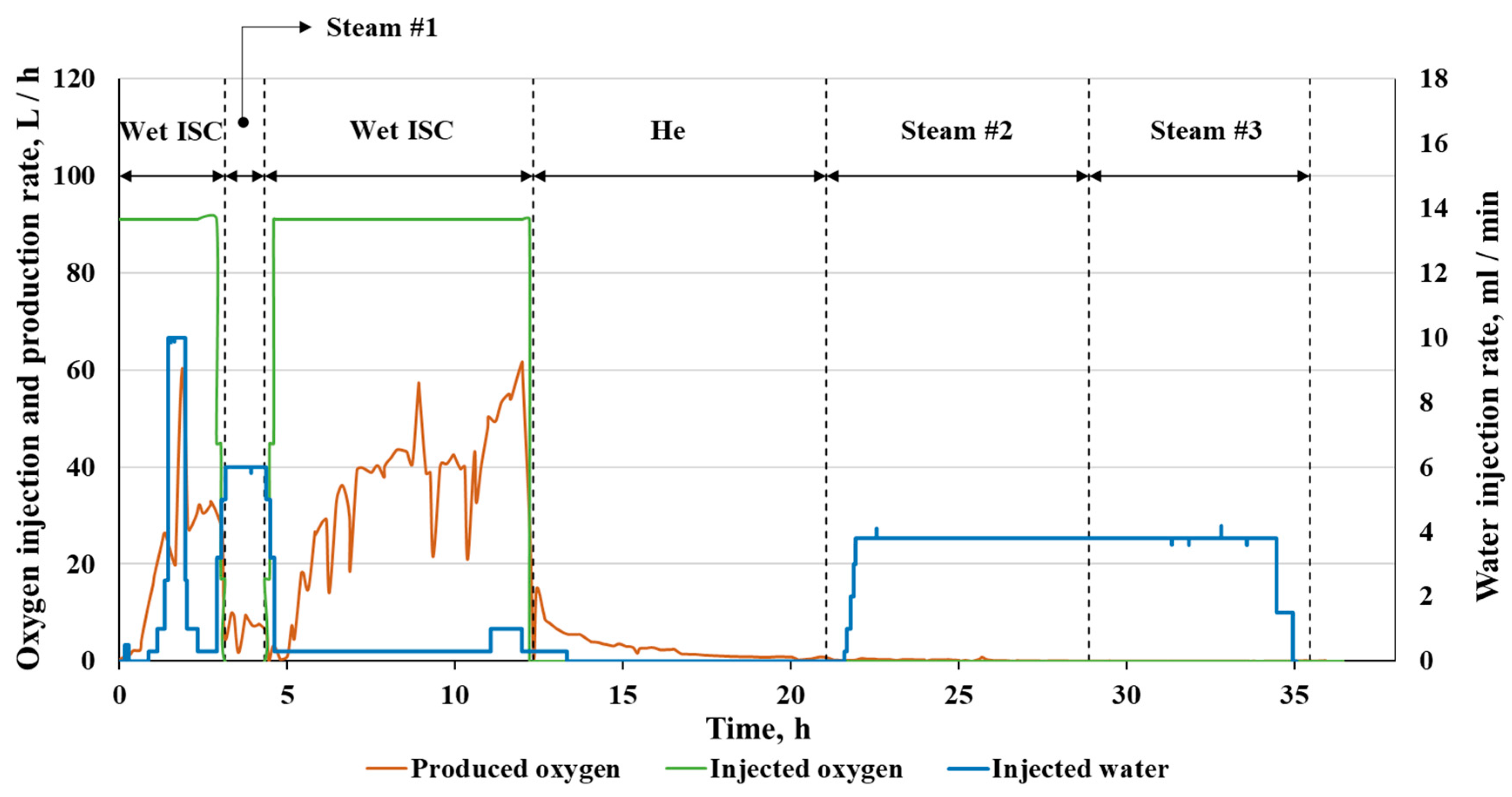
An experimental simulation was performed on an oil-saturated crushed core model in the presence of a nickel-based catalyst to study how catalytically enhanced ISC and steam injection influence heavy oil composition and properties. The experiment with alternating air and water injections (which turned into steam in the first heated zones of the reactor) was implemented in a combustion tube (CT) with simulated reservoir heterogeneities. The CT core holder was packed with double bulk porosity and incorporated pieces of consolidated core.
The experiment simulated target oil reservoir conditions under thermal stimulation. Pore pressure was equal to 8 MPa, the initial core model temperature—to 45 °C, and the ignition was made by raising the temperature of the first zone to 350 °C. A description of the stages of the experiment is given in Table 2.
At the time of 0 h 0 min, air injection into the CT with a flux of 40 m3/h/m2 (rate of 314 L(ST)/h) began. After 10 min, the temperature increase was recorded in zone 1 of the CT, which indicated the successful initiation of the ISC process. Soon, the temperature of the first zone reached 600 °C (Figure 1).
When the combustion front reached zone 2, water injection with a 10 mL/min flow rate was started to simulate wet ISC. Figure 2 below illustrates the volumetric rate of water injection versus time, oxygen injection, and production.
It can also be seen that at the time of 3.15 h, the water flow was set to 6 mL/min. At this moment, air injection was stopped, and the second stage of the experiment was started. In addition, to compensate for the pressure drop in the backpressure system, helium was injected into the gas sampling unit at a flow rate of 58.6 L/h.
After 4.33 h from the beginning of the first stage of air injection, steam injection was stopped, and air injection was initiated again. Therefore, the exothermic process at the time 7–8 h corresponds to the wet ISC, which is confirmed by temperature increase in CT zones 5–9 (Figure 1).
After 12.3 h from the start of the experiment, the temperature in zone 9 began to grow. So it was decided to end the experiment because the combustion front passed 75% of the CT length. According to the standard procedure, air injection was terminated, and helium was injected. However, for some reason, the temperature in zones 6–11 stayed at a level of 550–600 °C for a long time. Moreover, a slow and permanent temperature increase was detected in zones 7–10. This effect can be explained by the appearance of highly permeable channels in the core model, through which the main amount of gases, including injected helium, passed. While the previously injected air, which remained in the pore space at the periphery of the core model and the low-permeable zones, slowly reacted with the residual oil. As a result, partial oil oxidation occurred with the release of energy sufficient for further heating of zones 7–10.
After 19.4 h from the beginning of the experiment, thermal stimulation was continued in the steam injection mode while maintaining pressure in the gas sampling system with helium. For this aim, zones 1–5 were externally heated to 400 °C to create superheated steam.
At the moment of 25 h, the temperature in zone 7 began to decrease, followed by a temperature decrease in zones 8–12. It could mean that the whole amount of air saturating the oil and low-permeable parts of the core model reacted, and the exothermic oxidation ended. The energy released during the residual oxidation reactions was no longer enough to maintain the temperature of the core model under conditions of constant heat and mass transfer. Thus, the differential heating mode was consistently turned off, and the experiment ended after 29 h from the beginning.

2.2. Outlet Fluids

As a result of the experiment, about 9500 L of gases, 5.10 kg of oil, and 2.94 kg of water were produced from the outlet end of the CT in total. Figure 3 presents the dependencies of amounts of outlet fluids on experimental time. The most oil was displaced during the two stages of wet ISC and the first stage of steam injection, which were also crucial for oil production and upgrading. The most amount of water was produced naturally during the steam injection stages and the second stage of wet ISC (with an increased water injection rate). Moreover, the amounts of gases released from the output end of the CT were decreased during the steam injection stages, which is logically correct since no gases were injected into the reactor during those periods.
The material balance was calculated for hydrocarbon and non-hydrocarbon components. For this aim, masses of injected and produced oil were measured. Oil was also extracted from the core samples after the experiment, and the amount of residual petroleum coke was also revealed. It is worth noting that the amount of burnout oil was obtained from gas chromatography analysis.
The obtained data indicate the oil recovery factor for the whole experiment is 0.95, and about 4.4% of initially loaded oil burned during the ISC stages (Table 3). The error for the material balance is equal to −2.06%.
During the experiment, the gas analysis was conducted in an automatic regime. A comparison between the amounts of oxygen injected into and produced out of the reactor (CT) is shown in Figure 2. During the first stage of the wet ISC, in the time range from 0.15 to 3.15 h (Table 1), oxygen was injected into the CT at a rate of about 91 L/h. Moreover, more than half of injected oxygen was consumed by the oxidation reactions due to the combustion process. The average flow rate of unconsumed oxygen out of the reactor was 30 L/h. At the second stage of the wet ISC, in the time range from 4.33 to 12.35 h, the average rate of unconsumed oxygen out of the reactor was already 40 L/h. The peak volumetric rate reached 62 L/h. The curve has a non-linear form and enough intense fluctuations with an amplitude of about 40 L/h. After the second stage of the wet ISC, air injection was not performed.
The fractional composition of the outlet gas mixture, excluding oxygen component, is shown in Figure 4 (helium- and nitrogen-free basis). The need to present outlet gases in terms of volumetric rate (not in mol.%) is related to the error that can occur due to the different injection flows of air and helium at different stages of the experiment and is also associated with a strong dilution of the synthetic gas mixture with diluent gases.
According to the gas chromatography analysis, the average volumetric rate of carbon dioxide and monoxide in outlet flow was 23 L/h, and 5 L/h, respectively, during the first wet ISC. The curves have linear downtrends, with a maximum rate value at the moment of 1.89 h. At the steam injection stage, carbon dioxide and monoxide release rates are reduced to 5 L/h and 1 L/h, respectively. At the next stage of the wet ISC, the carbon mono- and dioxide flow rates returned to the values of the first wet ISC stage. Then at stages of He injection, Steam #2 and Steam #3, these gases were released with rates less than 1 L/h.
Except for the components mentioned above, mainly hydrocarbon gases such as methane, ethane, ethylene, propane, propylene, as well as hydrogen sulfide and hydrogen, were produced from the CT during the stages of wet ISC #1, Steam #1, and wet ISC #2. At the same time, during the helium purge, the yield of hydrocarbon gases doubled and then decreased to 0 L/h. At the stages of Steam #2–3, the rate of outlet flow of hydrocarbon gases increased to the values recorded at the wet ISC #1 stage but then decreased to almost 0 L/h.
At all stages of the experiment, hydrogen was released from the CT. The maximum rate of hydrogen outlet flow was 0.34 L/h. Nevertheless, the total accumulated volume of hydrogen was 2.10 L. The highest volumetric outlet rates were obtained at the stages of wet ISC and Steam #2–3, and the lowest—at the stage of helium injection.

3. Discussion

The achieved results are discussed with knee attention in Section 3.1, Section 3.2, Section 3.3 and Section 3.4 below, and the main general conclusions are highlighted.

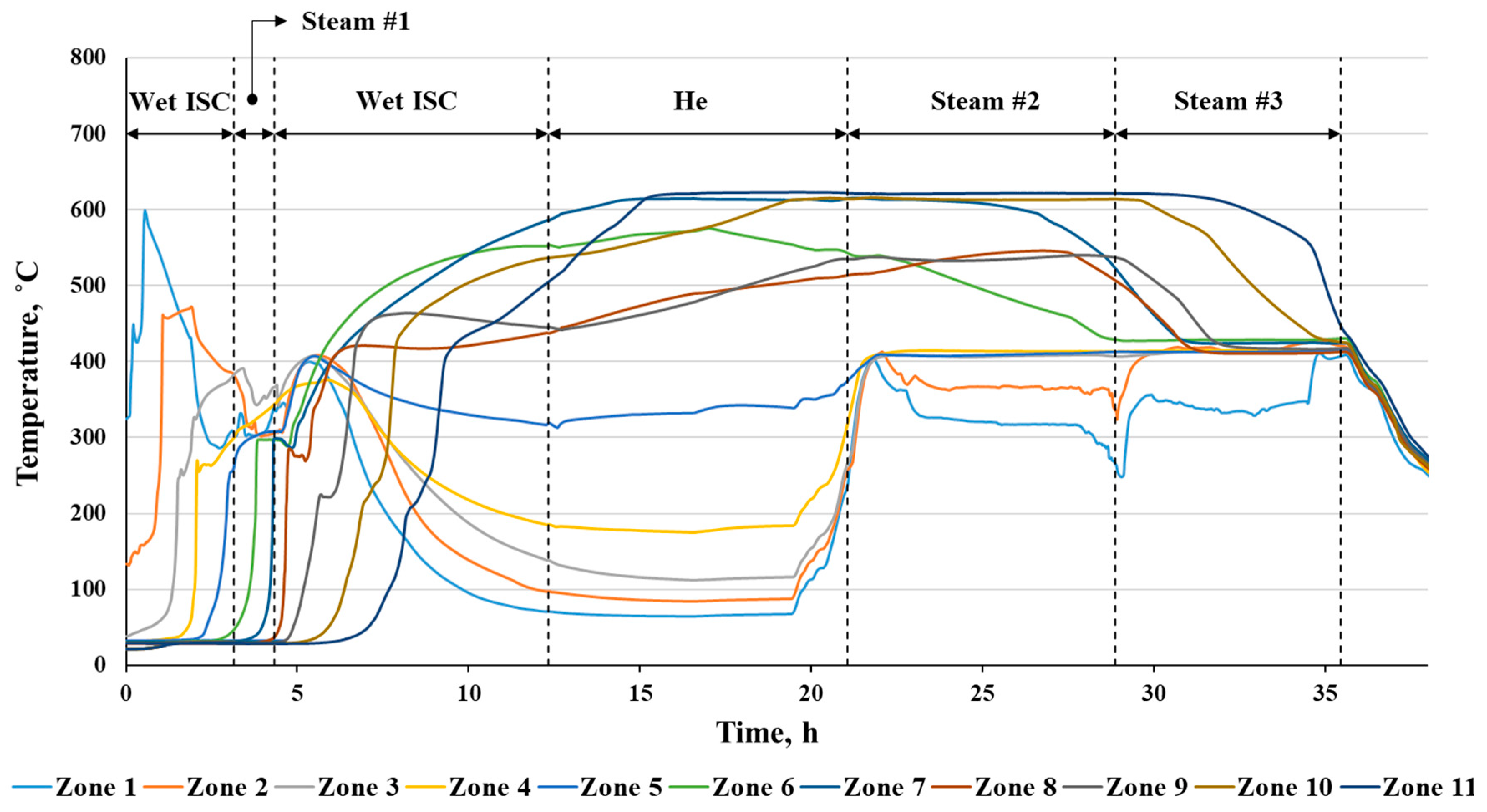
3.1. Temperature Profile Analysis

The temperature profiles of the CT zones (Figure 5), the graph of air injection and production (Figure 2), and the composition of the outgoing gas mixture (Figure 4) indeed confirm that the ISC was successfully initiated at two stages of the experiment, and the combustion front advanced in the forward direction. At each of these stages, sequentially, in zones 1–4 and then 5–11, temperatures significantly higher than 380 °C were reached (the boundary value for the low-temperature oxidation process [13]) with peak temperatures around 600 °C. At the same time, in both periods, from 0.15 to 3.15 h and from 4.33 to 12.35 h, a significant consumption of air oxygen can also be noted. More than half of all oxygen injected into the core model during these periods was consumed in oxidative processes. In addition, the active formation of carbon monoxide and dioxide was noted in the same periods. This fact also confirms the occurrence of the ISC process, including the high-temperature oxidation mode. At the same time, the temperature profiles of zones 4–7 have a flatter shape with the achievement of lower peak temperatures. Such temperature profiles are more typical for wet ISC. Moreover, the shape of the curves makes it possible to classify the combustion stage as an Incomplete (Partially Quenched) Wet Combustion process [13]. The temperature curves in Figure 1 related to these zones are located at different distances from each other, corresponding to the non-uniform combustion. From the zone 8 to 11, the combustion became more stable, and this period can be analyzed to calculate combustion parameters.
In the late stages of the experiment, after the step of helium injection for 5.1 h, the temperature of zones 6–11 continued to be at the level of 550–600 °C and did not decrease. This phenomenon can be explained by the oxidation of residual oil in low-permeable zones of the core model due to the interaction with air injected in the previous stages. In this case, oxidative reactions occurred, most likely, without the apparent formation of a combustion front. Thus, this stage has no separate peaks on zone temperature profiles. However, the concentrations of carbon dioxide and monoxide in the outlet gas stream increased, confirming hydrocarbons’ oxidation.

3.2. Outlet Gas Analysis

Leaving the CT, the gases went through the separation system, after which they were sent for analysis by a gas chromatograph. According to the analysis results, the simultaneous presence of significant amounts of carbon dioxide and carbon monoxide in the outlet gas stream was recorded at the stages of wet ISC. The fluxes of each component from the reactor were at the level of 10–30 L/h and 3–6 L/h for carbon dioxide and monoxide, respectively (Figure 5). This fact confirms the occurrence of high-temperature oxidation in the periods of the ISC [46,48,78]. It also results in comparatively high volumetric methane, ethylene and hydrogen rates, and almost the absence of hydrogen sulfide (Figure 6). So, there is a typical composition for hydrocarbon steam conversion and aquathermolysis but not thermal cracking. In turn, at the stage of steam injection, which separates the stages of the ISC, in the zones swept by the combustion front 4–5, a sharp drop in the release rate of combustion gases (to about 5 L/h of carbon dioxide and 2 L/h of carbon monoxide) and temperatures of the order 300–340 °C can be noticed. These facts testify to the quenching of the combustion front due to the insufficient oxygen supply caused by the stopped air injection. Hydrogen released during this period could be a product of petroleum coke gasification. An almost zero yield of carbon oxides was detected at other stages of the experiment, most likely, due to the absence of high-temperature oil oxidation processes.
Despite the above-described quenching of the combustion front with water, in the time range of 5.25–12.35 h, the relatively stable wet ISC occurred in zones 8–11. The combustion parameters calculated by formulas given in [13] for this period are presented in Table 4.
Simultaneous formation of carbon oxides, together with methane, ethane, ethylene, propylene, and other hydrocarbon gases, together with hydrogen sulfide at the stages of steam reinjections, most likely, indicates the occurrence of aquathermolysis and thermolysis of oil [46,48]. So, for example, thermal cracking (thermolysis) of the bitumen is a minor source of gases but can be clearly recognized due to the simultaneous release of ethane and hydrogen sulfide. It also can contribute to hydrogen production. In turn, the hydrogen formed in the experiment can also be spent on the hydroconversion of hydrocarbon feedstock. The intensification of aquathermolysis processes is also observed at the stage of Steam injection #3, which is confirmed by increased hydrogen sulfide release from the reactor. In this case, hydrogen sulfide was likely formed due to the thermal destruction of C-S bonds in hydrocarbons.
During the first cycle of the ISC, highly permeable channels were also probably formed, which then influenced the other stages of the experiment. The air injected at the next stage could break through such channels out of the CT, reducing the interaction time with hydrocarbons and the volume of oxygen interacted.
At the stage of helium injection, an increase in the rate of the outlet stream of light hydrocarbons (methane, ethylene, and propane) was observed. This effect is most likely caused by the blowdown of the reactor and the removal of hydrocarbon components from stagnant core model zones.
Hydrogen was also one of the components of the synthetic gas mixture. It was most actively released at wet ISC and Steam injections #2–3 stages. Hydrogen could be generated for the entire experimental time but in different zones of the core model, where the highest temperature and steam saturation were reached at that time. For example, at the beginning of the experiment, during the stages of ISC and the first steam injection cycle, hydrogen could be formed in zones 1–4 of the CT. Then it could be synthesized in zones 6–12 during helium injection. In addition, at the final stage of steam injection hydrogen can be formed both in zones 2–6 (with temperatures up to 400 °C) and in zones 7–12 (with temperatures above 400 °C).
In this case, the origin of the generated hydrogen can also be different. So, for example, petroleum coke could be the primary feedstock for hydrogen synthesis at the stage of the first cycle of steam injection and the second cycle of ISC (in the time range of 4.33–12.35 h, Figure 6). At the first cycle of ISC and during the steam reinjections, the main process contributing to the hydrogen generation could be the thermal cracking of oil. This process occurs in a wide temperature range, in a lack of oxygen, and with the release of accompanying gas components such as methane, carbon oxides, fatty gas components, and hydrogen sulfide (according to the chromatography analysis). At the same time, the almost complete absence of carbon monoxide in the synthetic gas mixture in the time range from 15 h to the end of the experiment (Figure 4), also confirms the possible occurrence of the water–gas shift reaction, leading to hydrogen production [45].
Thus, in the performed experiment, coke gasification is an important but not the primary process for hydrogen generation. However, some generated hydrogen could be consumed in subsequent reactions with hydrocarbons, where it acted as a proton donor and was not detected. Nevertheless, more likely, the majority of hydrogen produced could be formed due to oil thermal cracking. Thermolysis of hydrocarbons occurs at high temperatures in the absence of sufficient amounts of an oxidizing agent. This process is accompanied by the formation of methane, ethane-ethylene, propane-propylene, butane-butylene gas fractions, and hydrogen sulfide with simultaneous hydrogen generation. At the same time, the water–gas shift reaction also contributes to the generation of hydrogen, consuming the simultaneously formed carbon monoxide.
Similar findings were presented in studies of authors investigating thermal EOR methods for oil reservoirs [79,80]. So, hydrogen can be generated due to primary processes such as aquathermolysis, pyrolysis, and reforming of oil, and secondary processes such as generated coke gasification and water–gas shift reaction. Investigation of the oil gasification process showed that 80% of hydrogen was generated during the coke dehydrogenation stage and only 20%—during coke pyrolysis [63].

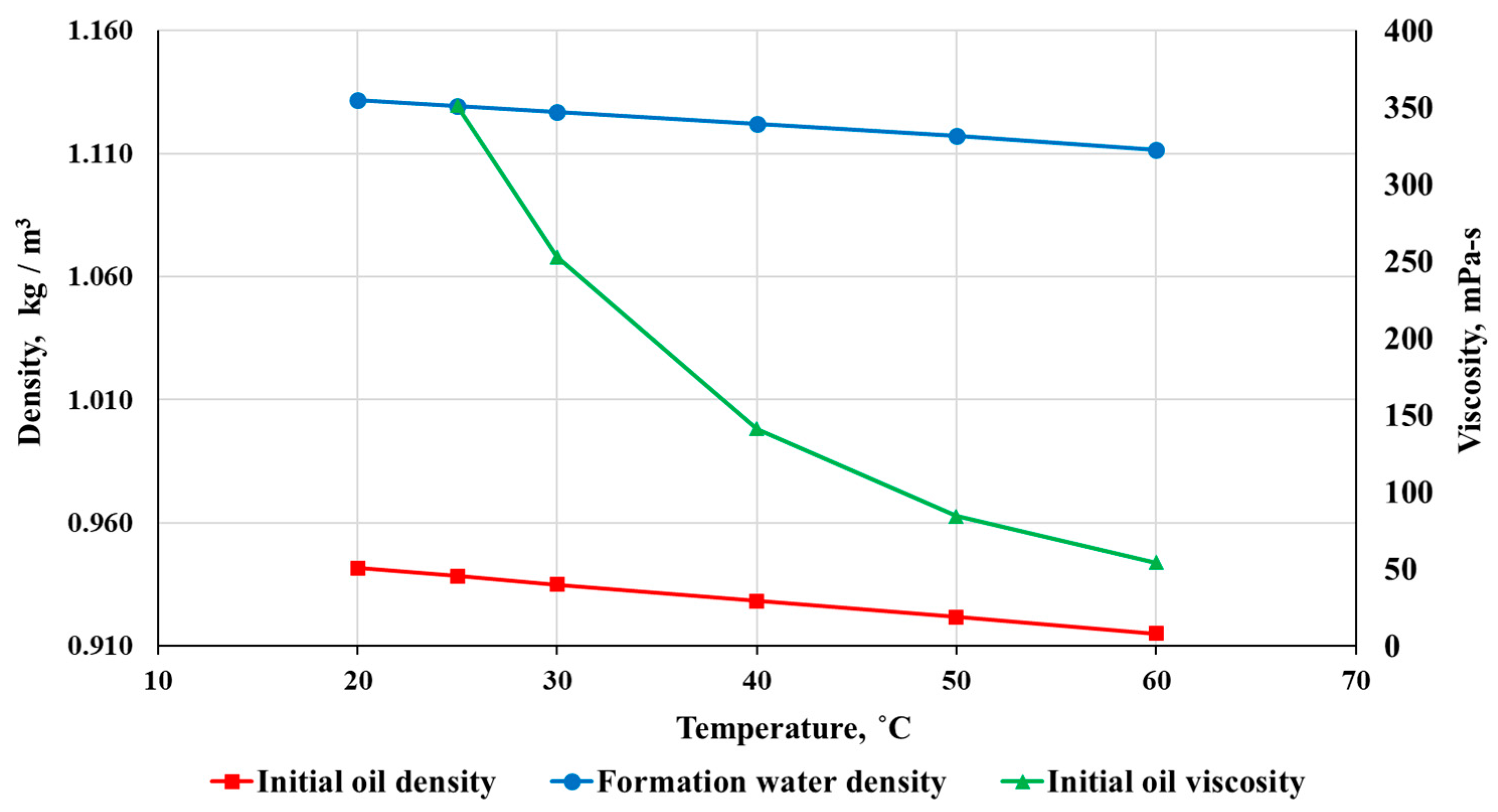
3.3. Effect on Oil Composition and Properties

During the experiment, about 5.1 kg of oil was displaced from the core model at the stages of ISC and Steam injection #1 (the oil recovery factor is 0.95). At the same time, there is a general trend towards a decrease in the density from 0.942 g/mL (°API = 18.2) up to 0.933 g/mL (°API = 19.7) and viscosity from 351 mPa-s up to 238 mPa-s of displaced oil relative to the original one. This effect is caused by the oil upgrading due to thermolysis, aquathermolysis, hydroconversion, and slight changes from sample to sample. Dissolution of CO2 can also lead to a decrease in oil density. The density and viscosity of oil displaced during the experiment at specific points in time are shown in Figure 7.
The fractional composition of the samples of displaced oil was investigated by the method of simulated distillation on an Agilent 6789B gas chromatograph. The obtained data are presented in Figure 8. Analysis of the given curves allows us to conclude that the oil sampled at the stages of combustion and Steam injection #1 (except for one sample of oil #6) turns out to be enriched in volatile C9–C18 fractions with minor changes in the content of high-boiling fractions (C36+), compared with the original oil. Such oil upgrading could occur both due to a thermal impact on oil and as a result of catalytic transformations of oil components intensified in the presence of in situ generated hydrogen.
In this study supported nickel-based catalyst was used to effectively accelerate hydrogen generation processes, such as steam reforming of natural gas [59,81,82], dry reforming [83,84], partial oxidation, autothermal reforming, coke gasification, and water–gas shift reaction. At the same time, nickel-based catalysts stimulate oil upgrading due to oil cracking and hydroprocessing processes.
It is well known that the presence of asphaltene species significantly affects the viscosity of crude oil. Therefore, the observed reduction in viscosity following the upgradation process can be attributed to the partial transformation of the original heavy crude oil’s asphaltene components and an increase in the amounts of saturated species. At high temperature, catalysts exhibit the ability to break C−S bonds in heteroatoms and break down larger molecules into smaller ones. Additionally, they facilitate other synergistic reactions like hydrogenation and ring opening, resulting in an oil with improved properties.
It is also known that hydroprocessing or hydrotreatment of oil contains a series of reactions, including hydrocracking, hydrodesulfurization, hydrodenitrogenation, hydrodeoxygenation, and hydrodemetallization. These reactions specifically involve breaking various bonds (C−S, C−N, C−C, C−O) present in the molecules that constitute heavy crude oil fractions. Supported nickel-based catalyst has the ability to significantly decrease the potential energy of some bonds and break these bonds (due to the strong acid sites), intensifying oil upgrading [32,85,86]. In addition, previously generated hydrogen promotes hydrogenation reaction. Activation of hydrogen on the catalyst’s surface, therefore, forms Ni−H bonds that help decrease the activity of condensation and aromatization reactions caused by hydrogenated free radicals.
The change in the elemental composition of oil samples produced during the experiment by specific time points is shown in Figure 9.
Elemental sulfur in produced oil samples could have increased, compared with the original oil, due to the prior release of light sulfur-depleted fractions and enrichment with heavier fractions. This phenomenon also influences the relative content of elemental carbon.

3.4. Residual Coke Content

After the experiment, the core model was extracted from the core holder, and the amounts of unreacted coke were determined using annealing. According to the coke distribution along the CT, an area of the first third of the CT can be distinguished with comparatively low coke content. This area presents zones with incomplete coke conversion related to the non-uniform propagation of the combustion front. In the second part of the CT, closer to the end, there is an increase in coke content. The increase can be caused by the displacement of hydrocarbons towards the output end of the rector and as a result of long-term maintenance of high temperatures in this area (CT zones 7–11). These changes can be distinguished visually (Figure 10).
Figure 11 shows the results of annealing core model samples taken after the experiment. The black dotted curve on this graph shows the change in the maximum temperatures reached in each zone of the CT along the reactor length.
Although the amount of unreacted coke only slightly changes over the zones of the core model, some conclusions can be made. For example, the hydrogen generated in the experimental time of 3.15–4.33 h (Figure 6) can be attributed precisely to the coke gasification process since no additional gases are formed during this process. So, hydrocarbon gases and hydrogen sulfide are formed during the oil thermal cracking and aquathermolysis. In addition, coke gasification, most likely, continued during the second cycle of the ISC.

4. Materials and Methods

4.1. Design of the Experiment

The purpose of the experiment was a laboratory simulation of hydrocarbon conversion processes at reservoir conditions and in the presence of core model heterogeneity during the in situ combustion process and steam injection. The experiment was conducted in a medium-pressure CT. The CT is a specialized laboratory setup used to simulate hydrocarbon transformations during high-temperature processes under reservoir conditions. A detailed description of the equipment used in the test was represented in papers [49,87]. During the Steam cycles, water was injected into the core holder and then evaporated in the first hot CT zones.
The central hypothesis of the test was an assumption on coke deposition during the ISC with further gasification at steam injection. A similar process was reported in [44] for the ISC pilot on a bituminous reservoir of Wolf Lake with the cyclic ISC and steam injection stages.
Thus, petroleum coke can be formed at the first stages of ISC, which is both a fuel for the combustion process at the high-temperature oxidation stage and a feedstock for hydrogen generation. It was assumed that coke would be obtained in the core model at the stage of ISC (some coke will be unreacted even after combustion front propagation). Then this coke would be gasified due to the subsequent injection of steam and air, leading to the synthesis of significant amounts of hydrogen.
It was proposed to simulate the quenching of a combustion front with water to increase the amount of unreacted coke remaining in the pore space of the core model after the passage of the combustion front. Despite that, the wet ISC process was chosen as a target. Wet ISC has a longer combustion front and is characterized by lower peak temperatures than normal ISC. Additionally, reservoir heterogeneity was simulated by creating a two-layer longitudinal core model and incorporating consolidated core samples. A two-layer core model with various porosity and permeability should contribute to the non-uniform propagation of the combustion front and the creation of zones with a high petroleum coke content. At the same time, if the combustion is quenched by steam (and by the interrupting of air injection), low-permeable zones stay not fully involved in the ISC. It preserves previously generated coke from oxidation for further gasification leading to hydrogen generation during steam injection (Figure 12).
To increase the probability of hydrogen generation and efficiency of oil upgrading due to oil thermolysis, aquathermolysis, and hydroconversion, the design of the experiment included two cycles of air and several cycles of steam injections. The general scheme of the test is presented in Figure 13.
Initial conditions simulate the average pressure, fluid saturations, and oil properties for the heavy oil field in the last stage of development in the Volga-Ural oil region in Russia. The main parameters of the experiment are presented in Table 5.

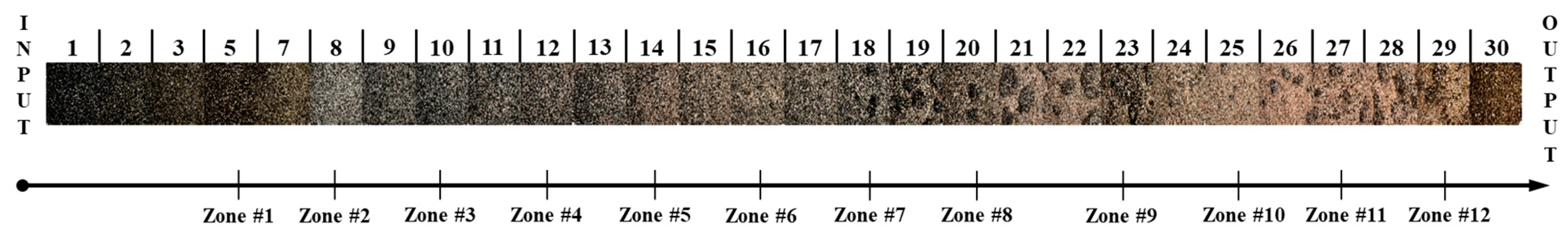
4.2. Preparation of the Core Model

The feature of the experiment is the usage of the core model, which has dual porosity and permeability. For this case, the CT was filled with two fractions of sand in the same volume proportions along the core holder with a boundary in the middle (Figure 14).
The bulk core model was prepared from quartz sand with fractions of 0.5–0.8 mm and 0.8–1.2 mm. The properties of the prepared core model are presented in Table 6.
Degassed oil and a model of formation water were used to create initial oil and water saturations. The properties of the used high-viscosity oil and the model of formation water are shown in Figure 15 and Table 7.
The core model’s initial water and oil saturations were created in two steps. In the first step, a mixture of sand, formation water, oil, and catalyst was loaded into the reactor. In the second stage, the core model was fully saturated with oil, followed by water injection to create fine hydrodynamic conductivity between CT ends and initial water saturation. Oil and water injections were performed at a pressure of 0.34 MPa to remove residual air.

4.3. Catalyst Preparation and Characterization

Nickel supported on alumina (α-Al2O3) carrier was chosen as a catalyst for the experiment, which is active in oil upgrading and hydrocarbon conversion to hydrogen. Raw catalyst is presented with nickel oxide particles supported on alumina. This industrial NIAP-03-01 catalyst was manufactured by NIAP-KATALYZATOR LLC (Russia) in the form of biconvex cylinders with seven holes. The catalyst pellets were crushed to the desired fraction (0.5–1.0 mm), then processed in a hydrogen flow for the activation and treated with ethanol and nitrogen for the passivation. So, the crushed catalyst is subjected to heat treatment at 400 °C in a hydrogen/nitrogen flow for 4 h. The mixture contains 20 vol.% of hydrogen and 80 vol.% of nitrogen. Then the catalyst was cooled down after the previous stage and soaked in ethanol for 1 h, avoiding contact with air. After this, the catalyst was dried in a nitrogen flow at room temperature until the alcohol was removed entirely. As a result, the catalyst could be used in an oxidative (air) atmosphere.
Such ex situ prepared catalyst can be delivered into the reservoir through the suspension together with steam or overheated water. Unsupported nickel-based catalysts can also be delivered into the reservoir in the form of a water solution of precursor, such as nickel nitrate, oxalate, acetate, and oleate, as well as ammonium salts and metal-containing acids, since they are easily decomposable at temperatures achievable in the reservoir due to the thermal stimulation, with the formation of Ni or NiO particles. However, in our case, the solid catalyst was prepared with manufacturer recommendations and loaded into the reactor (CT) before the experiment as a part of the core model.
SEM analysis was carried out using scanning electron microscope Quattro S (Thermo Fisher Scientific, Breda, The Netherlands) equipped with an Energy-Dispersive X-ray spectrometer (EDX mapping) XFlash 630 (Bruker, Billerica, MA, USA) to study the morphology and elemental composition of the catalyst particles. Backscattered electron mode was used to show the heterogeneity of the material composition. The main operating parameters used during catalyst investigation were an accelerating voltage of 10 kV and magnification of ×20,000–25,000.
Catalyst’s grain size distribution has a prevailing fraction of 3–10 microns (about 80%), whereas other grains have a range of 10–25 microns (less than 20%). At the same time, the majority of nickel particles have a size of the order of 60–80 nm. According to the obtained SEM data, nickel has a homogeneous distribution on the surface of aluminum oxide support (Figure 16). The elemental composition of the catalyst, derived from Energy Dispersive X-ray mapping, is presented in Figure 17 and summarized in Table 8. XRD and nitrogen adsorption were further used to analyze the catalyst.
XRD measurements for applied Ni-Al2O3 catalyst were carried out on the Huber G670 diffractometer using Co Kα radiation (λ = 1.78892 Å). The obtained XRD data are presented in Figure 18 (green curve). The figure also shows the characteristic spectrum lines of Ni at 2θ degrees of 52.3, 61.4, 92.5, and corundum at degrees of 29.8, 41.0, 44.1, 50.8, 61.8, 67.9, 70.6, 72.5, 72.6, 79.1, 81.2, 84.2, 89.1, 92.4, 92.9, and 97.4. It was revealed from the analysis that the catalyst contains 8.7 wt.% of nickel and 91.3 wt.% of corundum.
Determination of the catalyst’s specific surface area and pore volume was conducted with ASAP 2020K-C-MP analyzer from Micromeritics. The value of Brunauer–Emmett–Teller (BET) specific surface area was determined by the thermal desorption of nitrogen according to the standard [88] with a 2.5% measurement accuracy and equals 13.02 m2/g. Nitrogen adsorption isotherms were obtained at a temperature of −195.9 °C. The Barrett–Joyner–Halenda (BJH) adsorption and desorption pore size distributions are represented in Figure 19.

5. Conclusions

This study aimed to simulate a catalytically enhanced in situ combustion process alternated by steam (water) injections in a high-viscosity heavy oil reservoir. An important objective was to validate the assumption that simulated conditions intensify oil upgrading, including the influence of in situ generated hydrogen. The study also investigated the impact of heterogeneities on the process. These heterogeneities were artificially generated using consolidated core pieces and sand of different fractions.
During the experiment, two cycles of the ISC were successfully initiated, with the combustion front advancing in the forward direction. The temperatures reached in combustion zones were equal to 550–600 °C and are typical for the wet ISC. The oil recovery factor achieved was 0.95.
The thermal stimulation of the oil-saturated core model led to an upgrading of the original oil. Thus, oil displaced during the ISC processes and Steam injection #1 stage turned out to be enriched in volatile fractions of C9–C18, with a slight decrease in the content of high-boiling fractions. The density of the displaced oil also irreversibly decreased from 0.942 g/mL to up to 0.933 g/mL (about 0.937 g/mL on average). The processes of oil upgrading were inevitably affected by the introduced nickel-based catalyst and simultaneously synthesized hydrogen.
The conducted experiment qualitatively confirmed the possibility of in situ hydrogen generation during the cyclic ISC and steam injection. The total volume of hydrogen generated was 2.10 L. More than 51% of synthesized hydrogen was formed at the stages of wet ISC, and the rest was obtained during steam injection, most likely due to cracking and aquathermolysis of heavy oil components.
The residual amount of unreacted coke in the CT (about 1%) does not exceed the typical amount after the ISC process. Thus, petroleum coke was not the main source of hydrogen generation. Most likely, the predominant amounts of synthesized hydrogen were formed as a result of the thermal cracking of oil.
It should also be noted that the developed and tested experimental technique and design can be used in the following experiments. Further studies are planned to be carried out using natural core samples, including those with different combustion times and sweep of the core model, which will bring the experimental conditions closer to the real reservoirs.
The developing technology of subsurface hydrogen generation and oil upgrading implies a simultaneous increase in oil production, in situ oil upgrading, and hydrogen generation. This combination creates a synergistic effect on the process of deep oil upgrading. It can lead further to an additional decrease in oil recovery and processing costs. By adopting this technology, the oil and gas sector can also take a substantial stride towards energy transition, since decreased gas emissions during oil recovery and processing and possible use of synthesized hydrogen for energy generation (producing hydrogen as one of the target products).

Author Contributions

Conceptualization, P.A., E.P. and A.C.; methodology, P.A., E.P., A.C. and A.S.; validation, P.A., A.S. and A.C.; formal analysis, A.S. and E.P.; investigation, P.A., A.S., A.U. and A.C.; resources, E.P. and A.C.; data curation, P.A., A.S. and E.P.; writing—original draft preparation, P.A., A.S. and A.U.; writing—review and editing, E.P. and A.C.; visualization, P.A., A.S. and A.U.; supervision, E.P. and A.C.; project administration, A.C.; funding acquisition, A.C. All authors have read and agreed to the published version of the manuscript.

Funding

This work was supported by the Ministry of Science and Higher Education of the Russian Federation under agreement No. 075-10-2022-011 within the framework of the development program for a World-class Research Center.

Data Availability Statement

The data presented in this study are available on request from the corresponding author. The data are not publicly available due to the comprehensive but complex dataset.

Acknowledgments

The authors would like to thank the Center for Petroleum Science and Engineering of Skolkovo Institute of Science and Technology for supporting and assisting this research. Moreover, the authors would like to show their gratefulness to Nikolay Taraskin and Kirill Maerle for helping in performing experiments and analyzing experimental data.

Conflicts of Interest

The authors declare no conflict of interest. The funders had no role in the design of the study; in the collection, analyses, or interpretation of data; in the writing of the manuscript; or in the decision to publish the results.

References

  1. Allison, E.; Mandler, B. Heavy Oil; American Geosciences Institute: Alexandria, VA, USA, 2018. [Google Scholar]
  2. Omoregbe, O.; Hart, A. Global Trends in Heavy Oil and Bitumen Recovery and In-Situ Upgrading: A Bibliometric Analysis during 1900–2020 and Future Outlook. J. Energy Resour. Technol. Trans. ASME 2022, 144, 123007. [Google Scholar] [CrossRef]
  3. Zhao, Q.; Guo, L.; Wang, Y.; Jin, H.; Chen, L.; Huang, Z. Enhanced Oil Recovery and in Situ Upgrading of Heavy Oil by Supercritical Water Injection. Energy Fuels 2020, 34, 360–367. [Google Scholar] [CrossRef]
  4. Sheng, J.J. Steam Flooding, 1st ed.; Elsevier Inc.: Amsterdam, The Netherlands, 2013; ISBN 9780123865458. [Google Scholar]
  5. Wang, C.; Liu, H.; Pang, Z.; Wang, J.; Chen, C.; Wang, C.; Wu, Z. Enhance Oil Recovery for Steam Flooding: Low-Temperature Oxidative Decomposition of Heavy Oil with Air Injection. Energy Fuels 2015, 29, 6242–6249. [Google Scholar] [CrossRef]
  6. Sheng, J. Cyclic Steam Stimulation. In Enhanced Oil Recovery Field Case Studies; Gulf Professional Publishing: Houston, TX, USA, 2013; pp. 389–412. [Google Scholar] [CrossRef]
  7. Xu, A.; Mu, L.; Fan, Z.; Wu, X.; Zhao, L.; Bo, B.; Xu, T. Mechanism of heavy oil recovery by cyclic superheated steam stimulation. J. Pet. Sci. Eng. 2013, 111, 197–207. [Google Scholar] [CrossRef]
  8. Bao, Y.; Wang, J.; Gates, I.D. On the physics of cyclic steam stimulation. Energy 2016, 115, 969–985. [Google Scholar] [CrossRef]
  9. Butler, R.M.; McNab, G.S.; Lo, H.Y. Theoretical Studies on the Gravity Drainage of Heavy Oil during In-Situ Steam Heating. Esso Resour. Can. Ltd. 1981, 5, 455–460. [Google Scholar] [CrossRef]
  10. Bagci, S. The effect of fractures on the steam-assisted gravity drainage process. Energy Fuels 2004, 18, 1656–1664. [Google Scholar] [CrossRef]
  11. Ji, D.; Zhong, H.; Dong, M.; Chen, Z.; Jia, X. A Model to Estimate Heat Efficiency in Steam-Assisted Gravity Drainage by Condensate and Initial Water Flow in Oil Sands. Ind. Eng. Chem. Res. 2016, 55, 13147–13156. [Google Scholar] [CrossRef]
  12. Giacchetta, G.; Leporini, M.; Marchetti, B. Economic and environmental analysis of a Steam Assisted Gravity Drainage (SAGD) facility for oil recovery from Canadian oil sands. Appl. Energy 2015, 142, 1–9. [Google Scholar] [CrossRef]
  13. Sarathi, P.S. In-Situ Combustion Handbook—Principles and Practices; National Petroleum Technology Office, Department of Energy: Tulsa, OK, USA, 1999; Volume 9.
  14. Yang, M.; Harding, T.G.; Chen, Z. An Improved Kinetics Model for in Situ Combustion of Pre-Steamed Oil Sands. Energy Fuels 2017, 31, 3546–3556. [Google Scholar] [CrossRef]
  15. Abuhesa, M.B.; Hughes, R. Comparison of conventional and catalytic in situ combustion processes for ol recovery. Energy Fuels 2009, 23, 186–192. [Google Scholar] [CrossRef]
  16. Mallory, D.G.; Moore, R.G.; Mehta, S.A. Ramped Temperature Oxidation Testing and In Situ Combustion Projects. Energy Fuels 2018, 32, 8040–8056. [Google Scholar] [CrossRef]
  17. Chen, B. Investigation of In-Situ Combustion Kinetics Using the Isoconversional Principle; Stanford University: Stanford, CA, USA, 2012. [Google Scholar]
  18. Gutiérrez, D.; Moore, R.G.; Ursenbach, M.G.; Mehta, S.A. The ABCs of in-situ-combustion simulations: From laboratory experiments to field scale. J. Can. Pet. Technol. 2012, 51, 256–267. [Google Scholar] [CrossRef]
  19. Barzin, Y.; Moore, R.G.; Mehta, S.A.; Ursenbach, M.G.; Tabasinejad, F. A Comprehensive Kinetics Model for Light Oil Oxidation/Combustion Reactions under High Pressure Air Injection Process (HPAI). In Proceedings of the SPE Annual Technical Conference and Exhibition? New Orleans, LA, USA, 30 September–2 October 2013. [Google Scholar]
  20. Bousaid, I.S.; Ramey, H.J. Oxidation of Crude Oil in Porous Media. Soc. Pet. Eng. J. 1968, 8, 137–148. [Google Scholar] [CrossRef]
  21. Yang, X.; Gates, I.D. Combustion kinetics of Athabasca bitumen from 1D combustion tube experiments. Nat. Resour. Res. 2009, 18, 193–211. [Google Scholar] [CrossRef]
  22. Zhao, R.B.; Xia, X.T.; Luo, W.W.; Shi, Y.L.; Diao, C.J. Alteration of Heavy Oil Properties under In-Situ Combustion: A Field Study. Energy Fuels 2015, 29, 6839–6848. [Google Scholar] [CrossRef]
  23. Speight, J.G. The Chemistry and Technology of Petroleum; Taylor & Francis: Abingdon, UK, 2014. [Google Scholar]
  24. Mehrabi-Kalajahi, S.; Hadavimoghaddam, F.; Varfolomeev, M.A.; Salari, R.; Zinnatullin, A.L.; Vagizov, F.G. Effect of Different Water Content and Catalyst on the Performance of Heavy Oil Oxidation in Porous Media for in Situ Upgrading. Ind. Eng. Chem. Res. 2022, 61, 9234–9248. [Google Scholar] [CrossRef]
  25. Ovalles, C.; Filgueiras, E.; Morales, A.; Scott, C.E.; Gonzalez-Gimenez, F.; Embaid, B.P. Use of a dispersed iron catalyst for upgrading extra-heavy crude oil using methane as source of hydrogen. ACS Div. Fuel Chem. Prepr. 1998, 43, 521–523. [Google Scholar] [CrossRef]
  26. Weissman, J.G.; Kessler, R.V.; Sawicki, R.A.; Belgrave, J.D.M.; Laureshen, C.J.; Mehta, S.A.; Moore, R.G.; Ursenbach, M.G. Down-hole catalytic upgrading of heavy crude oil. Energy Fuels 1996, 10, 883–889. [Google Scholar] [CrossRef]
  27. Hovsepian, C.N.; Carbognani Ortega, L.; Pereira-Almao, P. Laboratory Two-Dimensional Experimental Simulation of Catalytic in Situ Upgrading. Energy Fuels 2016, 30, 3652–3659. [Google Scholar] [CrossRef]
  28. Li, Y.; Wang, Z.; Hu, Z.; Xu, B.; Li, Y.; Pu, W.; Zhao, J. A review of in situ upgrading technology for heavy crude oil. Petroleum 2021, 7, 117–122. [Google Scholar] [CrossRef]
  29. Golafshani, M.B.; Mehrabi-kalajahi, S.; Varfolomeev, M.A.; Sadikov, K.G.; Emelianov, D.A.; Rodionov, N.O.; Zinnatullin, A.L.; Vagizov, F.G. Improving the Performance of Heavy Oil Oxidation Using Oil- Soluble Copper-Based Catalysts in In Situ Combustion for the In Situ Upgrading Process. Energy Fuels 2023, 37, 6705–6714. [Google Scholar] [CrossRef]
  30. Schacht-Hernández, P.; Quintana-Solórzano, R.; Morelos-Santos, O.; Soto-Escalante, I.; Ancheyta, J. In Situ Upgrading of Heavy Crude Oil: Comparative Study of the Performance of Cu-, Fe-, Ni-, or Zr-Containing Water-Based Catalysts. Energy Fuels 2022, 36, 12580–12590. [Google Scholar] [CrossRef]
  31. Kayukova, G.P.; Mikhailova, A.N.; Kosachev, I.P.; Nasyrova, Z.R.; Gareev, B.I.; Vakhin, A.V. Catalytic Hydrothermal Conversion of Heavy Oil in the Porous Media. Energy Fuels 2021, 35, 1297–1307. [Google Scholar] [CrossRef]
  32. Guo, K.; Zhang, Y.; Shi, Q.; Yu, Z. The Effect of Carbon-Supported Nickel Nanoparticles in the Reduction of Carboxylic Acids for in Situ Upgrading of Heavy Crude Oil. Energy Fuels 2017, 31, 6045–6055. [Google Scholar] [CrossRef]
  33. Al-Marshed, A.; Hart, A.; Leeke, G.; Greaves, M.; Wood, J. Effectiveness of Different Transition Metal Dispersed Catalysts for In Situ Heavy Oil Upgrading. Ind. Eng. Chem. Res. 2015, 54, 10645–10655. [Google Scholar] [CrossRef] [Green Version]
  34. Alkhaldi, S.; Husein, M.M. Hydrocracking of heavy oil by means of in situ prepared ultradispersed nickel nanocatalyst. Energy Fuels 2014, 28, 643–649. [Google Scholar] [CrossRef]
  35. Hart, A.; Leeke, G.; Greaves, M.; Wood, J. Downhole heavy crude oil upgrading using CAPRI: Effect of steam upon upgrading and coke formation. Energy Fuels 2014, 28, 1811–1819. [Google Scholar] [CrossRef]
  36. Hashemi, R.; Nassar, N.N.; Pereira Almao, P. In situ upgrading of athabasca bitumen using multimetallic ultradispersed nanocatalysts in an oil sands packed-bed column: Part 2. Solid analysis and gaseous product distribution. Energy Fuels 2014, 28, 1351–1361. [Google Scholar] [CrossRef]
  37. Al-Marshed, A.; Hart, A.; Leeke, G.; Greaves, M.; Wood, J. Optimization of Heavy Oil Upgrading Using Dispersed Nanoparticulate Iron Oxide as a Catalyst. Energy Fuels 2015, 29, 6306–6316. [Google Scholar] [CrossRef]
  38. Masudi, A.; Muraza, O. Zirconia-Based Nanocatalysts in Heavy Oil Upgrading: A Mini Review. Energy Fuels 2018, 32, 2840–2854. [Google Scholar] [CrossRef]
  39. Alemán-Vázquez, L.O.; Torres-Mancera, P.; Ancheyta, J.; Ramírez-Salgado, J. Use of Hydrogen Donors for Partial Upgrading of Heavy Petroleum. Energy Fuels 2016, 30, 9050–9060. [Google Scholar] [CrossRef]
  40. Aleman-Vazquez, L.O.; Torres-Mancera, P.; Munoz, J.A.D.; Ancheyta, J. Batch reactor study for partial upgrading of a heavy oil with a novel solid hydrogen transfer agent. Energy Fuels 2020, 34, 15714–15726. [Google Scholar] [CrossRef]
  41. Liu, Y.; Fan, H. The effect of hydrogen donor additive on the viscosity of heavy oil during steam stimulation. Energy Fuels 2002, 16, 842–846. [Google Scholar] [CrossRef]
  42. Amrollahi Biyouki, A.; Hosseinpour, N.; Bahramian, A.; Vatani, A. In-situ upgrading of reservoir oils by in-situ preparation of NiO nanoparticles in thermal enhanced oil recovery processes. Colloids Surf. A Physicochem. Eng. Asp. 2017, 520, 289–300. [Google Scholar] [CrossRef] [Green Version]
  43. Hart, A.; Wood, J.; Greaves, M. In situ catalytic upgrading of heavy oil using a pelletized Ni-Mo/Al2O3 catalyst in the THAI process. J. Pet. Sci. Eng. 2017, 156, 958–965. [Google Scholar] [CrossRef]
  44. Hallam, R.J.; Hajdo, L.E.; Donnelly, J.K.; Resources, B.P.; Paul, R.; Co, B.P.E. Thermal Recovery of Bitumen at Wolf Lake. SPE Reserv. Eng. 1989, 4, 178–186. [Google Scholar] [CrossRef]
  45. Hajdo, L.E.; Hallam, R.J.; Vorndran, L.D.L. Hydrogen Generation during In-Situ Combustion. In Proceedings of the SPE 13661, California Regional Meeting, Bakersfield, CA, USA, 27–29 March 1985; pp. 675–689. [Google Scholar]
  46. Kapadia, P.R.; Kallos, M.S.; Gates, I.D. A Comprehensive Kinetic Theory to Model Thermolysis, Aquathermolysis, Gasification, Combustion, and Oxidation of Athabasca Bitumen. In Proceedings of the SPE 129660, SPE Improved Oil Recovery Symposium, Tulsa, OK, USA, 24–28 April 2010; pp. 1–31. [Google Scholar]
  47. Kapadia, P.R.; Kallos, M.S.; Leskiw, C.; Gates, I.D.; Kapadia, P.R.; Kallos, M.S.; Leskiw, C.; Gates, I.D. Potential for Hydrogen Generation during In Situ Combustion of Bitumen. In Proceedings of the SPE 122028, SPE EUROPEC/EAGE Annual Conference and Exhibition, Amsterdam, The Netherlands, 8–11 June 2009; pp. 1–14. [Google Scholar]
  48. Kapadia, P.R.; Wang, J.; Kallos, M.S.; Gates, I.D. Practical process design for in situ gasification of bitumen. Appl. Energy 2013, 107, 281–296. [Google Scholar] [CrossRef]
  49. Askarova, A.; Afanasev, P.; Popov, E.; Mikitin, E.; Darishchev, V. Application of oil in situ combustion for the catalytic methane conversion in the porous medium of the gas reservoir. J. Pet. Sci. Eng. 2023, 220, 111256. [Google Scholar] [CrossRef]
  50. Muraza, O.; Galadima, A. Aquathermolysis of heavy oil: A review and perspective on catalyst development. Fuel 2015, 157, 219–231. [Google Scholar] [CrossRef]
  51. Wu, C.; Lei, G.-L.; Yao, C.-J.; Sun, K.-J.; Gan, P.-Y.; Cao, Y.-B. Mechanism for reducing the viscosity of extra-heavy oil by aquathermolysis with an amphiphilic catalyst. J. Fuel Chem. Technol. 2010, 38, 684–690. [Google Scholar] [CrossRef]
  52. Qu, X.; Li, Y.; Li, S.; Wang, J.; Xu, H.; Li, Z. Thermal cracking, aquathermolysis, and their upgrading effects of Mackay River oil sand. J. Pet. Sci. Eng. 2021, 201, 108473. [Google Scholar] [CrossRef]
  53. Vakhin, A.V.; Sitnov, S.A.; Mukhamatdinov, I.I.; Aliev, F.A.; Kudryashov, S.I.; Afanasiev, I.S.; Petrashov, O.V.; Varfolomeev, M.A.; Nurgaliev, D.K. Aquathermolysis of heavy oil in reservoir conditions with the use of oil-soluble catalysts: Part III–changes in composition resins and asphaltenes. Pet. Sci. Technol. 2018, 36, 1857–1863. [Google Scholar] [CrossRef]
  54. Fau, G.; Gascoin, N.; Steelant, J. Hydrocarbon pyrolysis with a methane focus: A review on the catalytic effect and the coke production. J. Anal. Appl. Pyrolysis 2014, 108, 1–11. [Google Scholar] [CrossRef]
  55. Karimi, S.; Bibak, F.; Meshkani, F.; Rastegarpanah, A.; Deng, J.; Liu, Y.; Dai, H. Promotional roles of second metals in catalyzing methane decomposition over the Ni-based catalysts for hydrogen production: A critical review. Int. J. Hydrogen Energy 2021, 46, 20435–20480. [Google Scholar] [CrossRef]
  56. Al Alwan, B.A.; Shah, M.; Danish, M.; Al Mesfer, M.K.; Khan, M.I.; Natarajan, V. Enhanced methane decomposition over transition metal-based tri-metallic catalysts for the production of COx free hydrogen. J. Indian Chem. Soc. 2022, 99, 100393. [Google Scholar] [CrossRef]
  57. Li, Y.; Li, D.; Wang, G. Methane decomposition to CO x -free hydrogen and nano-carbon material on group 8–10 base metal catalysts: A review. Catal. Today 2011, 162, 1–48. [Google Scholar] [CrossRef]
  58. Xu, J.; Froment, G.F. Methane Steam Reforming, Methanation and Water-Gas Shift: 1. Intrinsic Kinetics. AIChE J. 1989, 35, 88–96. [Google Scholar] [CrossRef]
  59. Matsumura, Y.; Nakamori, T. Steam reforming of methane over nickel catalysts at low reaction temperature. Appl. Catal. A Gen. 2004, 258, 107–114. [Google Scholar] [CrossRef]
  60. Rostrup-Nielsen, J.R. Catalytic Steam Reforming. Catal. Sci. Technol. 1984, 5, 1–117. [Google Scholar] [CrossRef]
  61. Lopeman, T.; Anbari, H.; Leeke, G.; Wood, J. Numerical Modeling of Toe-to-Heel Air Injection and Its Catalytic Variant (CAPRI) under Varying Steam Conditions. Energy Fuels 2023, 37, 237–250. [Google Scholar] [CrossRef] [PubMed]
  62. Li, Y.; Manrique, E.J.; Kovscek, A.R. Progress toward Pilot-Scale Simulation of In-Situ Combustion Incorporating Geomechanics. SPE Reserv. Eval. Eng. 2023, 26, 152–166. [Google Scholar] [CrossRef]
  63. Yang, S.; Huang, S.; Jiang, Q.; Yu, C.; Zhou, X. Experimental study of hydrogen generation from in-situ heavy oil gasification. Fuel 2022, 313, 122640. [Google Scholar] [CrossRef]
  64. Zhang, Y.; Yao, M.; Gao, S.; Sun, G.; Xu, G. Reactivity and kinetics for steam gasification of petroleum coke blended with black liquor in a micro fluidized bed. Appl. Energy 2015, 160, 820–828. [Google Scholar] [CrossRef]
  65. Zhang, Y.; Wang, J.; Zhang, X.; Sun, G. Experimental Study of Petroleum Coke Steam Gasification Catalyzed by Black Liquor in a Fluidized Bed. Energy Procedia 2014, 61, 472–475. [Google Scholar] [CrossRef] [Green Version]
  66. Chen, Y.F.; Yin, H.; He, D.L.; Gong, H.F.; Liu, Z.Z.; Liu, Y.Q.; Zhang, X.M.; Pu, W.F. Low temperature oxidized coke of the ultra-heavy oil during in-situ combustion process: Structural characterization and evolution elucidation. Fuel 2022, 313, 122676. [Google Scholar] [CrossRef]
  67. Ba, Z.; Zhao, J.; Li, C.; Huang, J.; Fang, Y.; Zhang, L.; Kong, L.; Wang, Q. Developing efficient gasification technology for high-sulfur petroleum coke to hydrogen-rich syngas production. Fuel 2020, 267, 117170. [Google Scholar] [CrossRef]
  68. Wu, Y.; Wang, J.; Wu, S.; Huang, S.; Gao, J. Potassium-catalyzed steam gasification of petroleum coke for H2 production: Reactivity, selectivity and gas release. Fuel Process. Technol. 2011, 92, 523–530. [Google Scholar] [CrossRef]
  69. Karimi, A.; Semagina, N.; Gray, M.R. Kinetics of catalytic steam gasification of bitumen coke. Fuel 2011, 90, 1285–1291. [Google Scholar] [CrossRef]
  70. Lan, C.C.; Zhang, S.H.; Liu, X.J.; Liu, R.; Lyu, Q. Kinetic behaviors of coke gasification with CO2 and H2O. ISIJ Int. 2021, 61, 167–173. [Google Scholar] [CrossRef]
  71. Wang, Z.; Ouyang, P.; Cui, L.; Zong, B.; Wu, G.; Zhang, Y. Valorizing petroleum coke into hydrogen-rich syngas through K-promoted catalytic steam gasification. J. Energy Inst. 2020, 93, 2544–2549. [Google Scholar] [CrossRef]
  72. Mahamulkar, S.; Yin, K.; Agrawal, P.K.; Davis, R.J.; Jones, C.W.; Malek, A.; Shibata, H. Formation and Oxidation/Gasification of Carbonaceous Deposits: A Review. Ind. Eng. Chem. Res. 2016, 55, 9760–9818. [Google Scholar] [CrossRef]
  73. Zamani, A.; Maini, B.; Pereira-Almao, P. Experimental study on transport of ultra-dispersed catalyst particles in porous media. Energy Fuels 2010, 24, 4980–4988. [Google Scholar] [CrossRef]
  74. Afanasev, P.; Popov, E.; Cheremisin, A.; Berenblyum, R.; Mikitin, E.; Sorokin, E.; Borisenko, A.; Darishchev, V.; Shchekoldin, K.; Slavkina, O. An experimental study of the possibility of in situ hydrogen generation within gas reservoirs. Energies 2021, 14, 5121. [Google Scholar] [CrossRef]
  75. Aounallah, K. Efficient Simulation and Analysis of the Effects of Permeability on the In-Situ Combustion of Heavy Oils. In Proceedings of the SPE Annual Technical Conference and Exhibition? Calgary, AB, Canada, 30 September–2 October 2019. [Google Scholar]
  76. Awoleke, O.G.; Castanier, L.M.; Kovscek, A.R. An Experimental Investigation of In-Situ Combustion in Heterogeneous Media. In Proceedings of the Canadian Unconventional Resources and International Petroleum Conference, Calgary, AB, Canada, 19–21 October 2010. [Google Scholar]
  77. Greaves, M.; Al-Honi, M. Three-Dimensional Studies of In-Situ Combustion-Horizontal Wells Process with Reservoir Heterogeneities. J. Can. Pet. Technol. 2000, 39. [Google Scholar] [CrossRef]
  78. Kapadia, P.R.; Kallos, M.S.; Gates, I.D. Potential for hydrogen generation from in situ combustion of Athabasca bitumen. Fuel 2011, 90, 2254–2265. [Google Scholar] [CrossRef]
  79. Okere, C.J.; Sheng, J.J. Review on clean hydrogen generation from petroleum reservoirs: Fundamentals, mechanisms, and field applications. Int. J. Hydrogen Energy 2023, in press. [Google Scholar] [CrossRef]
  80. Wei, W.; Wang, J.; Afshordi, S.; Gates, I.D. Detailed analysis of Toe-to-Heel Air Injection for heavy oil production. J. Pet. Sci. Eng. 2020, 186, 106704. [Google Scholar] [CrossRef]
  81. Pirez, C.; Fang, W.; Capron, M.; Paul, S.; Jobic, H.; Dumeignil, F.; Jalowiecki-Duhamel, L. Steam reforming, partial oxidation and oxidative steam reforming for hydrogen production from ethanol over cerium nickel based oxyhydride catalyst. Appl. Catal. A Gen. 2016, 518, 78–86. [Google Scholar] [CrossRef]
  82. Kho, E.T.; Scott, J.; Amal, R. Ni/TiO2 for low temperature steam reforming of methane. Chem. Eng. Sci. 2016, 140, 161–170. [Google Scholar] [CrossRef]
  83. Naeem, M.A.; Al-Fatesh, A.S.; Fakeeha, A.H.; Abasaeed, A.E. Hydrogen production from methane dry reforming over nickel-based nanocatalysts using surfactant-assisted or polyol method. Int. J. Hydrogen Energy 2014, 39, 17009–17023. [Google Scholar] [CrossRef]
  84. Li, D.; Nakagawa, Y.; Tomishige, K. Methane reforming to synthesis gas over Ni catalysts modified with noble metals. Appl. Catal. A Gen. 2011, 408, 1–24. [Google Scholar] [CrossRef]
  85. Rahimi, P.M.; Gentzis, T. The Chemistry of Bitumen and Heavy Oil Processing. In Practical Advances in Petroleum Processing; Springer: New York, NY, USA, 2006; ISBN 9780387257891. [Google Scholar]
  86. Rabee, A.I.M.; Mekhemer, G.A.H.; Osatiashtiani, A.; Isaacs, M.A.; Lee, A.F.; Wilson, K.; Zaki, M.I. Acidity-reactivity relationships in catalytic esterification over ammonium sulfate-derived sulfated zirconia. Catalysts 2017, 7, 204. [Google Scholar] [CrossRef] [Green Version]
  87. Khakimova, L.; Askarova, A.; Popov, E.; Moore, R.G.; Solovyev, A.; Simakov, Y.; Afanasiev, I.; Belgrave, J.; Cheremisin, A. High-pressure air injection laboratory-scale numerical models of oxidation experiments for Kirsanovskoye oil field. J. Pet. Sci. Eng. 2020, 188, 106796. [Google Scholar] [CrossRef]
  88. BSISO9277:2010; Determination of the Specific Surface Area of Solids by Gas Adsorption—BET Method. BSI: London, UK, 2010.
Figure 1. Temperature distribution in CT zones during the experiment.
Catalysts 13 01172 g001
Figure 2. Volumetric rate of water injection and oxygen injection and production during the experiment.
Catalysts 13 01172 g002
Figure 3. Amounts of fluids produced during the experiment.
Catalysts 13 01172 g003
Figure 4. Production volumetric rates of main components of outlet gas mixture.
Catalysts 13 01172 g004
Figure 5. Temperature profiles by CT zones on experimental time.
Catalysts 13 01172 g005
Figure 6. The cumulative volume of hydrogen produced in each of the experimental stages.
Catalysts 13 01172 g006
Figure 7. The density and viscosity of displaced oil at 25 °C by samples.
Catalysts 13 01172 g007
Figure 8. Fractional composition of displaced oil by samples.
Catalysts 13 01172 g008
Figure 9. The content of elemental sulfur, nitrogen, hydrogen, and carbon in oil samples.
Catalysts 13 01172 g009
Figure 10. The appearance of core samples taken from the core holder after the experiment by zones.
Catalysts 13 01172 g010
Figure 11. Distribution of unreacted coke along the length of CT, obtained by annealing (yellow curve) and maximum achieved temperatures in the core holder (black dotted curve).
Catalysts 13 01172 g011
Figure 12. Schematic illustration of the experimental steps with alternation of the ISC and steam injections.
Catalysts 13 01172 g012
Figure 13. Workflow of the experiment.
Catalysts 13 01172 g013
Figure 14. Photo of loading the core model into the core holder, keeping high-permeable (#1) and low-permeable (#2) zones.
Catalysts 13 01172 g014
Figure 15. Viscosity and density of oil and formation water model.
Catalysts 13 01172 g015
Figure 16. Morphological structure of Ni-Al2O3 catalysts in the mode of secondary electrons (a), backscattered electrons (b)—SEM microphotographs.
Catalysts 13 01172 g016
Figure 17. The distribution of elements on the catalyst surface.
Catalysts 13 01172 g017
Figure 18. XRD pattern of the applied catalyst.
Catalysts 13 01172 g018
Figure 19. BJH adsorption and desorption pore size distribution of applied catalyst.
Catalysts 13 01172 g019
Table 1. Comparison of the current and conventional thermal EOR methods for heavy oil and bitumen recovery.
#MethodReservoir
Depth
Temperature,
°C
ApplicabilityMain EffectsEcological AspectsDifficulties
1Steam flood/CSSShallow to medium (up to 1500 m)200–350Heavy oil and bitumen recovery,
aerial,
vertical and horizontal wells
Bitumen and oil viscosity reduction,
upgrade of produced oil (with catalyst)
Significant water consumptionWide and simple implementation
2SAGDShallow 200–350Heavy oil and bitumen recovery
horizontal well
Bitumen and oil viscosity reduction,
upgrade of produced oil (with catalyst)
Significant water consumptionOne or two horizontal wells needed
3ISCDeep reservoirs (up to 3000 m)400–700Heavy oil, bitumen, conventional oil recoveryBitumen and oil viscosity reduction
in situ oil upgrade, improvement of oil with catalyst
Small water injection, release of carbon oxides Required high-quality engineering support, difficult to manage
4Electrical heatingShallow 200–300Heavy oil and bitumen recovery,
horizontal well
Bitumen and oil viscosity reduction,
in situ oil upgrade
No water injection,
low carbon oxides release,
low environmental impact
Loses of energy during transfer to depth,
horizontal well required for intensive recovery
5In situ catalytic upgradingUp to 3000 m200–300Heavy oil, conventional oil recoveryOil viscosity reduction,
in situ oil upgrade
Reduction in carbon oxides emissions (during oil processing)Mainly in well bottom space,
high permeability required
6Combined CSS with catalyst and ISC * Shallow to medium (up to 1500 m)300–700Heavy oil and bitumen recovery,
NOVEL: hydrogen production
Bitumen and oil viscosity reduction,
in situ oil upgrade, further improvement of oil with catalyst
Moderate water consumption,
reduction in carbon oxides emissions
Required high-quality engineering support
* Method developing in the current study.
Table 2. Main stages of the experiment.
#Name of the StageTime, HourNote
1Start of the air injection0The beginning of the active stage of the experiment
2Wet in situ combustion #10.15–3.15Ignition and running of the wet combustion
3Steam #13.15–4.33Quenching of the combustion front by steam, stopping air injection
4Wet in situ combustion #24.33–12.35The second stage of air injection
5He12.35–19.44Try on the experiment completion, end of air injection, combustion front passed 75% of the length of the CT
6Steam #219.44–29.07A restart of steam injection since the continuous exothermic reactions in several CT zones
7Steam #329.07–35.46Continuation of steam injection with heating of the first CT zones
8End of the experiment35.46–38.00End of steam injection, depressurizing, and cooling of the CT
Table 3. The material balance and recovery factor of oil.
Initial oil, g3181.28
Residual oil, g42.41
Recovered oil, g3036.54
-Recovered at wet ISC stages, g1135.17
-Recovered at Steam stages, g1797.09
-Recovered at Helium purge, g104.28
Burnout oil, g141.40
Residual coke, g26.56
Gathered oil, g3246.91
Error, %−2.06
Recovery factor0.95
Table 4. Summary of stabilized combustion parameters.
ParameterValue
Aver. combustion front temperature, °C400
Combustion front velocity, m/h0.124
O2/Fuel ratio, m3(ST) × kg−17.43
Air/Fuel ratio, m3(ST) × kg−135.38
Injected oxygen to carbon oxides, %13.56
Reacted oxygen to carbon oxides, %31.36
(CO2 + CO)/CO ratio2.80
(CO2 + CO)/N2 ratio0.04
Apparent atomic H/C ratio7.19
Table 5. The operating parameters of the test.
ParameterValue
Pore pressure, MPa/psi8/1160
Initial temperature, °C27–30
Combustion initiation temperature, °C350
Air injection rate TMFC, st. L/h314
Water injection rate, mL/min0.3–1.0
Steam injection rate, mL/min0.3–6.2
Initial oil saturation50–60%
Phase transition temperature, °C295
Table 6. Core model properties.
ParameterValue
Porosity of the high-permeable zone (#1), %37.3
Porosity of the low-permeable zone (#2), %35.7
Permeability of high-permeable zone (#1), D4.95
Permeability of low-permeable zone (#2), D4.70
Average initial oil saturation, %0.62
Table 7. Composition of the formation water model.
Component of the Water SolutionConcentration,
g/L
NaCl175.47
CaCl2 × 2H2O37.05
MgCl2 × 6H2O22.42
Na2SO4 × 10H2O3.05
Table 8. The mass and atomic content of elements.
ElementsRelative Content (wt.%)Relative Content (Atom.%)
Al50.0541.83
O38.0253.59
Ni11.934.58
Sum100100
Disclaimer/Publisher’s Note: The statements, opinions and data contained in all publications are solely those of the individual author(s) and contributor(s) and not of MDPI and/or the editor(s). MDPI and/or the editor(s) disclaim responsibility for any injury to people or property resulting from any ideas, methods, instructions or products referred to in the content.

