
Preparation of CuS/PbS/ZnO Heterojunction Photocatalyst for Application in Hydrogen Production

1
Department of Chemical and Materials Engineering, National Kaohsiung University of Science and Technology, Kaohsiung 807, Taiwan
2
Department of Engineering Science, National Cheng Kung University, Tainan 701, Taiwan
*
Author to whom correspondence should be addressed.
Catalysts 2022, 12(12), 1677; https://doi.org/10.3390/catal12121677
Submission received: 29 October 2022
/
Revised: 11 December 2022
/
Accepted: 12 December 2022
/
Published: 19 December 2022
(This article belongs to the Special Issue Structured Semiconductors in Photocatalysis)
Abstract
:A hexagonal wurtzite ZnO photocatalyst was prepared via a precipitation method. CuS nanoparticles (NPs) and PbS quantum dots (QDs) were loaded onto ZnO via a hydrothermal method to obtain a CuS/PbS/ZnO heterojunction photocatalyst. The CuS/PbS/ZnO photocatalyst obtained via the abovementioned method has significant absorption capabilities in the ultraviolet to near-infrared spectral regions, and effectively reduced the recombination of electron–hole pairs during a photocatalytic reaction. Electron microscope images showed that in the CuS/PbS/ZnO photocatalyst prepared at 130 °C, the particle size of the PbS QDs was approximately 5.5–5.7 nm, and the bandgap determined from the Tauc plot was 0.84 eV; this catalyst demonstrated the best water splitting effect. Furthermore, after adding a 0.25 M mixed solution of Na2S and Na2SO3 as the sacrificial reagent in photocatalysis for 5 h, the hydrogen production efficiency from water splitting reached 6654 μmol g−1 h−1.
1. Introduction
With industrial development and rapid population growth, humanity has accelerated the consumption of the Earth’s resources, especially fossil fuels and forest resources. Some scholars have pointed out that, among the energy sources on Earth, petroleum can be used for about 40 years, natural gas for 60 years, and coal for 200 years. The concentration of carbon dioxide in the atmosphere due to the heavy usage of fossil fuels has reached a record high, exacerbating the greenhouse effect and causing rapid melting of the Arctic ice cap and global climate change. These phenomena are extremely detrimental to the sustainable development of human civilization. Therefore, all countries worldwide are actively undertaking research and development to secure new energy resources, with the aim of discovering an energy system to replace petroleum.
The calorific value of hydrogen is very high. Hydrogen can generate 142 million joules of heat energy per kilogram, which is three times that of gasoline and three and a half times that of natural gas. Hydrogen combustion can generate higher energy density, along with water, and will not produce greenhouse gases such as carbon dioxide, rendering it a form of clean energy. If hydrogen can be produced sustainably, combined with safe and efficient storage, transportation, and utilization, a platform for the sustainable use of hydrogen energy can be established to transform the current “petroleum economy” society into a clean and zero-carbon “hydrogen economy” society.
Solar energy can be regarded as an inexhaustible resource. The average light energy reaching the Earth is approximately 1.7 × 10¹⁷ W, and 1% of this energy is equivalent to providing the world’s 7.4 billion people with 200 days of energy consumption. If this solar energy can be effectively harnessed, the efficiency of energy usage can be improved, and huge progress can be made towards realizing the vision of establishing low-carbon nations and sustainable development. In recent years, the utilization of semiconductor photocatalysts for converting solar energy has become an important research direction. Semiconductor photocatalysts are used for water splitting to produce hydrogen [1,2], as well as in photocatalysis [3], the degradation of organic pollutants [4], and biomass energy conversion [5], all of which can be used to find reliable and stable solutions for environmental issues.
The current shortage of traditional energy requires the emergence of alternative energy sources. Among them, hydrogen energy is one of the high-profile energy sources, and there are more and more reports on the production of H2. The advantage of this work is that the materials used are not expensive, which reduces the cost of synthesis. The photocatalyst synthesis method is a hydrothermal method, and the process is simple.
Photocatalytic water splitting using solar energy to produce hydrogen was first proposed by Japanese scholars Fujishima and Honda in 1972. The titanium dioxide electrode of the anode absorbs light, and its valence band electrons excite the conduction band. Electrons come to the platinum electrode along the circuit to generate hydrogen. The holes on the titanium dioxide of the anode react with water to generate oxygen. Concurrently, hydrogen gas is generated on the platinum cathode; this phenomenon is the well-known Honda–Fujishima effect [6].
The method of electrochemically producing H2 from H2O is to put the cathode, anode and membrane in water and apply voltage to anode to produce H+, which then reacts with the electrons on the cathode to produce H2. Moreover, the strategy of photochemical production of H2 is to place a material that can absorb light energy in water, and through the irradiation of sunlight, the electrons of the material jump from the valence band to the conduction band, generating electron–hole pairs, and H+ reacts to produce H2. These two methods of producing H2 are the methods that are currently being discussed and researched, and it is expected that they can replace the traditional methods of producing H2 in the future. These two methods can be linked together. In fact, photocatalyst degradation, photocatalyst hydrogen production, solar cells, etc., are all combined and used together [7].
In photocatalytic systems, the main function of the photocatalyst is to absorb the solar energy of different wavelengths to conduct reactions. Photocatalytic materials, such as TiO2 [8], ZnO [9], CdS [10], and BiVO4 [11], have been developed for hydrogen production via water splitting. As ultraviolet radiation only accounts for 4% of sunlight, the wavelength of visible light accounts for a much larger percentage. In order to further extend the absorption range of the photocatalyst to the visible region of sunlight and adjust the redox potential to increase the efficacy of hydrogen production, different metal ions such as Pt, Au, Cu, and other transition metals can be added to [12,13,14] or combined with other semiconductor molecular structures to form heterojunction composite photocatalytic compounds [15,16,17], such as CdS@ZnO, CuS/ZnO, ZnO/ZnS, etc., which have heterojunction photocatalytic potential. In this manner, the original bandgap of the semiconductor can be altered to achieve effective electron–hole separation and enhance the efficiency of hydrogen production. For the CuS material, the reduction potential is −0.48 eV and the oxidation potential is +1.18 eV, while the reduction potential of water is 0 eV and the oxidation potential is +1.23 eV. It is revealed that the reduction potential of CuS is lower than that of water. When CuS receives energy, it is suitable for the reduction reaction of water to generate hydrogen; the energy gap of CuS is 1.66 eV, which belongs to the visible light absorption range. However, due to the poor optical stability of semiconductors with narrow bandgaps, the high rate of electron–hole recombination in the photocatalytic hydrogen production process leads to poor hydrogen production efficiency. In order to improve the hydrogen production efficiency, in their research, Wang et al. added Na2S and Na2SO3 as sacrificial reagents to effectively reduce electron–hole recombination [18]. In 1996, Alivisatos reported on the use of quantum dots (QDs) to control and adjust the size of semiconductor materials [19] in order to improve the solar absorption and bonding problems encountered with narrow bandgap semiconductors, and increase the photocatalytic hydrogen production efficiency.
The PbS QDs and CuS loaded onto ZnO in this study can absorb light in the near-infrared range during the photocatalytic reaction, and thus the photocatalyst is not limited by the range of UV and visible wavelength. The size of the PbS QDs can also be adjusted by changing the light wave absorption position of the photocatalyst.
When the conduction band potential of the photocatalyst is lower than the reduction potential of water (0 V vs. NHE, pH = 0), and the valence potential is higher than the oxidation potential of water (1.23 V vs. NHE, pH = 0), the photocatalyst absorbs light energy greater than the bandgap value, resulting in electron–hole pair separation. The electron transitions to the conduction band to reduce the hydrogen ions in the water to hydrogen, and the holes left in the valence band oxidize the oxygen ions in the water to generate oxygen; this process is termed photolysis by the semiconductor photocatalyst. Due to its bandgap of 3.2 eV, TiO2 can only absorb in the UV region of the solar spectrum: its photoelectric conversion efficiency is limited, and it is subject to electron–hole recombination, which affects the overall photocatalytic performance.
Nandi et al. loaded ZnO NPs and CdS NPs onto a CuS photocatalyst and adjusted the energy band relationship of the photocatalyst through the heterostructure, which effectively improved the efficiency of photocatalytic degradation [20]. Chang et al. prepared dendritic PbS@CuS photocatalysts by a hydrothermal method and used NaCl, Na2S, and Na2SO3 as sacrificial reagents for photocatalytic hydrogen production, achieving a hydrogen production efficiency of 1736 μmol h−1 g−1 [3]. Shi et al. first synthesized PbS with QDs and then prepared a PbS@ZnO/graphene oxide photocatalyst. Through the multiple exciton generation of PbS QDs, a good cooperative effect with graphene oxide was produced, which effectively facilitated electron generation and electron–hole separation and improved the efficiency of photocatalytic hydrogen production [21]. Liu et al. prepared a (ZnS-PbS)/Au/TiO2 photocatalyst via a hydrothermal method, where the loaded PbS QDs enhanced the absorption range of the photocatalyst from the near-infrared zone to the visible light region. Moreover, 20 wt% methanol was used as a sacrificial reagent for hydrogen production, which afforded an efficiency of 5011 μmol h−1 g−1 [22]. Wang et al. electrochemically modified a ZnO rod/reduced graphene (rGO)/CdS composite with CuS at room temperature to obtain a good heterostructure material. These studies show that CuS nanoparticles play a key role in enhancing the visible light response, and exhibit excellent catalytic performance. A visible-light photocatalytic H2 production rate of 1073 μmol h−1 g−1 was obtained with a CuS-ZnO/rGO/CdS heterostructure containing 0.23% CuS and 1.62% CdS [23].
Thus far, many ZnO-based substrates have been prepared by doping with transition metals or rare earth metal nanoparticles to reduce the electron–hole recombination rate and extend the light response into the visible region [24,25]. The generation of composites with other semiconductors has also been used to form heterostructures that combine bandgaps and different properties to enhance photocatalytic activity. However, if energy can be absorbed in the near-infrared region, the efficiency of photocatalytic hydrogen production could be further improved [26].
The aforementioned research results demonstrate that the photocatalytic efficiency of photocatalysts can be improved by loading a narrow bandgap semiconductor on the photocatalyst substrate to form a heterojunction. Therefore, in this study, CuS NPs and PbS QDs were loaded onto the surface of a ZnO photocatalyst to improve the bandgap relationship of the photocatalyst by utilizing sulfide with a narrow bandgap and increasing the absorption range of the photocatalyst in the visible light region and the near-infrared region, so as to improve the photocatalytic hydrogen production efficiency.
2. Results and Discussion
2.1. Analysis of Material Properties
The prepared heterojunction photocatalyst was analyzed using transmission electron microscopy (TEM), as is shown in Figure 1. Figure 1a shows that ZnO prepared via the precipitation method has a rectangular shape and a particle size of approximately 323.8 nm. The sulfide CuS NPs prepared via the hydrothermal method at 130 °C had a size of approximately 35.7 nm, and presented a sheet-like morphology similar to the shape reported by Saranya et al. [27]. The particle size of the PbS QDs was approximately 5.5–5.7 nm, and the particle shape was approximately spherical, which is similar to that of the PbS QDs prepared by Liu and colleagues [22].
The high magnification TEM image of the photocatalyst (Figure 1b) shows a lattice spacing of 0.247 nm for ZnO, corresponding to the (101) crystal face of hexagonal wurtzite; the lattice spacing of the CuS (101) crystal plane was 0.326 nm. From Figure 1c, the lattice spacing of the (200) plane of PbS QDs was 0.296 nm, which is consistent with the results of Sun and Chang et al. [3,7] and is consistent with the XRD results presented hereinafter. The TEM image of the prepared CuS/PbS/ZnO photocatalyst was analyzed by energy-dispersive X-ray spectroscopy (EDX) (as shown in Figure 1d), whereby Cu, Pb, S, Zn, and O were clearly observed, in addition to C originating from the carbon-coated copper mesh itself. Thus, it was confirmed that the CuS NPs and PbS QDs were successfully loaded onto the ZnO photocatalyst.
The XRD data for the prepared CuS/PbS/ZnO photocatalyst are shown in Figure 2. The characteristic peaks of hexagonal wurtzite ZnO were observed at 2 θ values of 31.8°, 34.5°, 36.3°, 47.6°, 56.6°, 62.9°, 66.4°, 68.0°, and 69.1°, corresponding to the (100), (002), (101), (102), and (110) crystal faces; the data are consistent with JCPDS card no. 36-1451 [28]. The characteristic peaks of the loaded CuS NPs were observed at 27.3°, 27.8°, 29.4°, 31.9°, 48.1°, 52.7°, and 59.1°, corresponding to the (100), (102), (103), (110), (108), and (116) crystal faces, consistent with JCPDS card no. 06-0464 [29]. The characteristic peaks of PbS were apparent at 26.0°, 30.1°, 43.1°, 51.0°, 53.5°, 62.6°, 68.9°, 70.9°, and 78.9°, corresponding to the (111), (200), (220), (311), (222), (400), (331), (420), and (422) crystal faces, consistent with JCPDS card no. 05-0592 [3]. Thus, CuS NPs and PbS QDs were successfully loaded onto the ZnO photocatalysts at 100 °C, 130 °C, 150 °C, and 170 °C by the hydrothermal method.
As is shown in Figure 2, the characteristic peaks of the loaded CuS at 31.9° and 48.0° overlapped with the characteristic peaks of ZnO at 31.8° and 47.5°, which intensified the peaks. The characteristic peaks of the loaded PbS at 62.6°and 68.9° overlapped with those of ZnO at 62.9° and 69.1°, leading to higher intensities. This indicates the presence of CuS and PbS in the photocatalyst. Moreover, these peaks were more intense for the CuS/PbS/ZnO photocatalyst prepared at higher hydrothermal temperature because the formation of sulfides was more complete under the hydrothermal environment [30].
2.2. Spectral Properties of Prepared Heterostructure Photocatalysts
Table 1 shows ZnO, PbS/ZnO, CuS/ZnO, and CuS/PbS/ZnO photocatalysts incident at a single wavelength light to detect the absorbance of the photocatalysts. It can be found that single composition of ZnO photocatalyst absorbs UV (300–350 nm), but ZnO does not absorb from VIS. to NIR (400–1800 nm). Comparing PbS/ZnO and CuS/ZnO, it can be seen that ZnO-loaded PbS QDs can enhance the absorption of 400–1800 nm; while the ZnO-loaded CuS can enhance the absorption of 350–1800 nm, the above two carriers can improve the absorption of ZnO. Further comparison can be found that for the wavelength of 350–600 nm, CuS is more improved; as for PbS QDs, it is more improved at 800–1800 nm.
The UV-VIS-NIR spectra of the CuS/PbS/ZnO photocatalysts prepared at various hydrothermal temperatures are shown in Figure 3, and the dotted line in Figure 3 represents the position of the maximum absorption wavelength of sulfide quantum dots synthesized by different hydrothermal temperatures, which can confirm the quantum confinement effect of quantum dots. When the hydrothermal temperature is lower, the smaller size of synthesized quantum dots is produced and spectrum present the blue-shift of the absorption wavelength is occurred. The CuS/PbS/ZnO photocatalysts prepared at all the hydrothermal temperatures had significant absorption bands from the near-infrared to the visible light region. The photocatalysts prepared at 100 °C and 130 °C absorbed more strongly at wavelengths of 380–760 nm. In comparison, the photocatalysts prepared at 150 °C and 170 °C had weaker absorption in the visible spectral region. The maximum absorption wavelength was shifted from 1435 nm for the sample prepared at 170 °C to 817 nm for the congener prepared at 100 °C, which suggests that the absorption of the photocatalyst prepared using the lower-temperature hydrothermal conditions shifted towards the shorter wavelength. Hence, it was concluded that the sulfide QDs prepared at lower temperatures had a smaller particle size, and the bandgap was widened due to the quantum confinement effect, which resulted in a blue-shift of the absorption [31].
The bandgaps of the sulfide QDs and ZnO photocatalysts were obtained via an analysis of the Tauc plots. Figure 4 shows the Tauc plot for the CuS/PbS/ZnO photocatalysts prepared at different hydrothermal temperatures. The CuS/PbS/ZnO photocatalyst had two bandgaps: a lower bandgap of PbS, and a higher bandgap of ZnO. As can be deduced from Figure 4, the bandgap of ZnO increased from 2.95 eV to 3.10 eV and the bandgap of PbS QDs decreased from 0.71 eV to 0.55 eV for the CuS/PbS/ZnO photocatalysts prepared in the hydrothermal temperature range of 100–170 °C. The bandgap of the PbS QDs prepared at a hydrothermal temperature of 130 °C was approximately 0.84 eV, which corresponds to PbS QDs of approximately 5.5 nm in the TEM image in Figure 1a. The relationship between the particle size and bandgap of PbS QDs is consistent with the study of Liang and co-workers [32]. Guchhait et al. also indicated that smaller PbS QDs particles should have a larger bandgap, which could shift the absorption from the near-infrared region to the visible light region, resulting in a blue-shift phenomenon [33].
Electron–hole pair recombination in the photocatalyst was investigated by PL spectral analysis. When the photocatalyst absorbs light energy, the electrons will transition from the ground state to the excited state, and the electrons will fall back to the ground state and generate fluorescence. This process is termed electron–hole pair recombination. The degree of electron–hole recombination in the photocatalyst determines the fluorescence intensity [29].
Figure 5 shows the PL spectrum of the prepared photocatalyst. Figure 5a shows the PL spectrum of the ZnO photocatalysts loaded with different sulfides. Fluorescence was generated in the wavelength range of approximately 400 nm to 800 nm, and the strongest fluorescence intensity was at a wavelength of 600 nm. Non-loaded ZnO produced the strongest fluorescence intensity, at a wavelength of 600 nm, whereas the fluorescence intensity decreased significantly for the ZnO photocatalyst loaded with the CuS NPs and PbS QDs, indicating that the loaded sulfide QDs effectively reduced the electron–hole recombination rate of the photocatalyst [34]. In comparison with the PbS/ZnO and CuS/ZnO photocatalysts, the fluorescence intensity generated by the CuS/PbS/ZnO photocatalyst was the lowest, which indicates that when CuS NPs and PbS QDs were simultaneously loaded onto the ZnO photocatalyst, the sulfide QDs and ZnO photocatalysts approached each other more closely, which effectively reduced the recombination of electron–hole pairs [35]. Yendrapati et al. [29] pointed out that the higher the peak value of the PL, the stronger the fluorescence intensity generated by the photocatalyst, corresponding to a faster electron–hole recombination rate. In contrast, the lower the peak value of the PL, the weaker the fluorescence intensity generated by the photocatalyst, indicating a slower electron–hole recombination rate.
Figure 5b shows the PL spectrum of the CuS/PbS/ZnO photocatalysts prepared at different hydrothermal temperatures. The CuS/PbS/ZnO photocatalysts prepared at different hydrothermal temperatures also emitted the maximum fluorescence intensity at 600 nm. The fluorescence intensity of the photocatalysts prepared at temperatures from 170 to 130 °C decreased gradually, where the photocatalyst prepared at 130 °C had the lowest fluorescence intensity. This is because the particle size of the sulfide QDs prepared at a lower hydrothermal temperature was smaller, and the bandgap of the sulfide QDs increased due to the quantum confinement effect, which effectively facilitated the separation of the electron–hole pairs and reduced the incidence of recombination. Notably, the highest PL peak intensity was observed for the photocatalyst prepared at 100 °C. This might be due to the hydrothermal temperature being too low, the crystallinity of the sulfide QDs being low, or crystal defects, which may have led to a high electron–hole pair recombination rate [36].
2.3. Hydrogen Production by Water Splitting with Photocatalysts
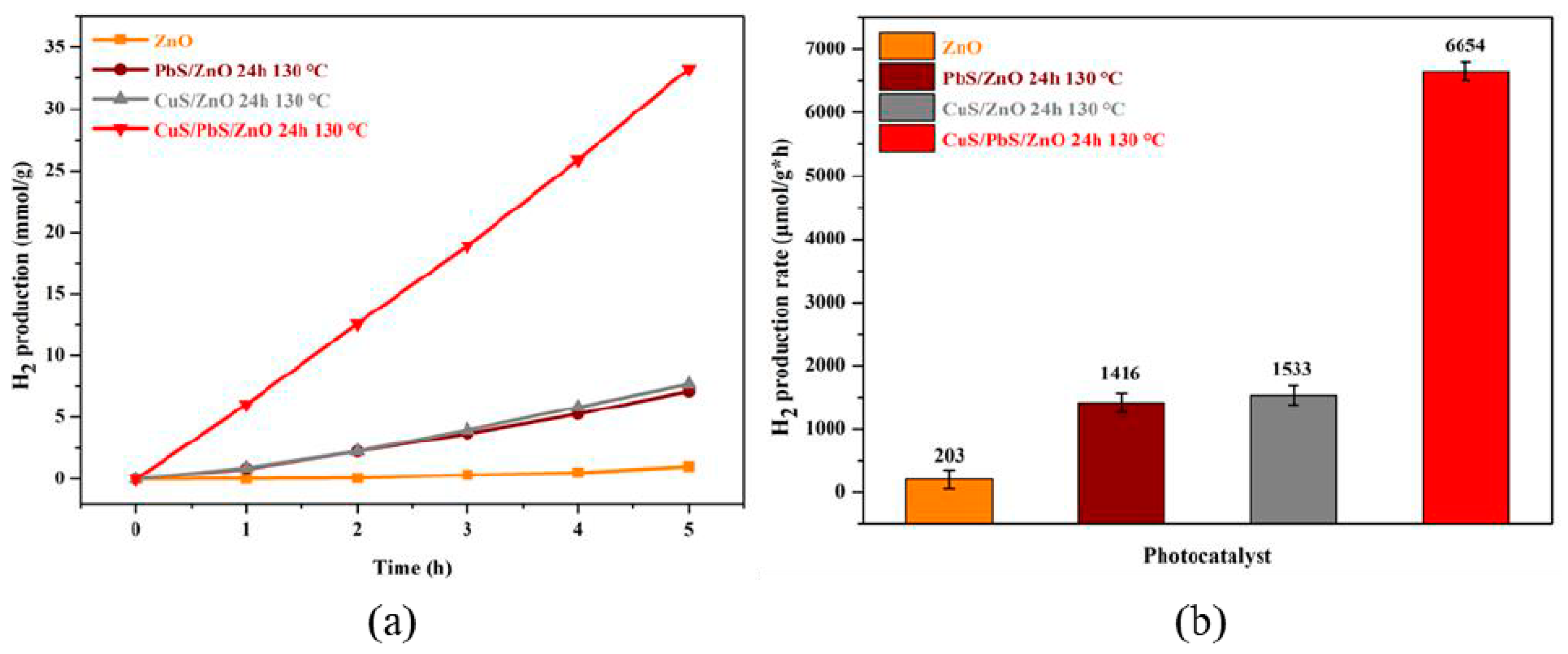
Figure 6 shows the hydrogen production efficiency of the respective photocatalysts in a 0.25 M aqueous mixed solution of Na2S and Na2SO3 as sacrificial reagents. The photocatalytic efficiency of the photocatalyst was studied by irradiating the aqueous solution containing the photocatalyst and sacrificial reagents with light generated by a solar simulator for 5 h. Figure 6a shows that the hydrogen production of the ZnO photocatalyst loaded with sulfide QDs was better than that of the non-loaded ZnO photocatalyst, and the hydrogen production achieved with the respective photocatalysts increased with time. CuS and PbS of the CuS/ZnO and PbS/ZnO photocatalysts facilitated energy absorption from the near-infrared to visible light region. PbS and CuS are prone to photocorrosion; thus, the hydrogen production rates of the CuS/ZnO and PbS/ZnO photocatalysts were lower. As is shown in Figure 6b, the hydrogen production achieved with the ZnO photocatalyst without any loading was 203 μmol g−1 h−1, whereas the hydrogen production of the CuS/PbS/ZnO photocatalyst was 6654 μmol g−1 h−1, which is 32 times that of the non-loaded ZnO photocatalyst. The CuS/PbS/ZnO photocatalyst had a higher hydrogen production rate, because the simultaneous loading of PbS QDs and CuS NPs not only facilitated absorption in the near-infrared and visible light regions, but the prepared ternary CuS/PbS/ZnO heterojunction photocatalyst was also more efficient. The effective electron–hole separation reduced the incidence of recombination [35].
Wang et al. reported that CuS/ZnS nanomaterials exhibit high visible light-induced H2 generation activity. The H2 generation rate increases with increasing Cu2+ ions. However, as with other cocatalysts, when the maximum amount of Cu2+ is reached (above 7 mol %), the hydrogen evolution rate decreases significantly. This is due to light shielding by excess CuS, which reduces the number of active sites on the surface [37].
Figure 7 shows the hydrogen production experiment of loading different contents of CuS NPs on PbS/ZnO and adding Na2S and Na2SO3 mixture (0.25 M) as a sacrificial reagent. It exhibits that as the amount of CuS NPs loaded onto PbS/ZnO increases, the hydrogen production will increase. When the CuS NPs loading is 2 wt.%, the hydrogen production is the highest, and when the loading reaches 3 wt.% and 4 wt.% the hydrogen production of the photocatalyst decreased. The reason is that the over-loaded CuS NPs shield the specific surface area of PbS/ZnO, greatly reducing the active sites and light absorption of PbS/ZnO.
TON specifies the maximum use that can be made of a catalyst for a special reaction under defined reaction conditions by the number of molecular reactions or reaction cycles occurring at the reactive center up to the decay of activity.
The calculation formula of TON:
Hydrogen production rate (μmole × min−1)/amounts of photocatalyst (μmole)
In order to obtain the hydrogen production effect of a single-component photocatalyst and heterogeneous photocatalyst (CuS/PbS/ZnO) in a monochromatic light environment, the authors designed the following experiments:
50 μmole of CuS, PbS, ZnO and CuS/PbS/ZnO were used for the hydrogen production experiment under the monochromatic light source environment between 300 nm and 1200 nm (0.25 M mixed solution of Na2S and Na2SO3 as the sacrificial reagent). The relevant data collection Table 2 and Table 3 are as follows.
From the table ‘Evaluation of single and heterojunction photocatalyst activities at monochromatic light’, it can be seen that the TON of each component of a single-component photocatalyst is smaller than that of heterojunction photocatalyst under the environment of monochromatic light, which can also explain that the heterojunction synthesized by hydrothermal method photocatalyst has better hydrogen production rate.
Figure 8 shows hydrogen production in the presence of the CuS/PbS/ZnO photocatalysts prepared at different hydrothermal temperatures. The photocatalytic reaction proceeded in the presence of the photocatalyst without the addition of a sacrificial reagent (as is shown in Figure 8a), where the photocatalyst prepared at 130 °C afforded the best hydrogen production. The hydrogen production curves of the photocatalysts prepared at hydrothermal temperatures in the range of 150–170 °C were similar. This is due to the quantum confinement effect, because the particles of sulfide QDs prepared at lower hydrothermal temperature (130 °C) were smaller, which increased the bandgap of the sulfide QDs and effectively separated the electron–hole pairs. However, the particle size of the sulfide QDs prepared at higher hydrothermal temperatures (150 and 170 °C) was relatively larger; thus, the hydrogen production was lower than that achieved with the photocatalysts prepared at 130 °C. Moreover, after five hours of the photocatalytic process, the hydrogen production was lower for the photocatalyst prepared at a hydrothermal temperature of 100 °C. This might be because the hydrothermal temperature was low, and the crystallinity of the prepared sulfide QDs was low; thus, it was easy to generate crystal defects, leading to the recombination of the electron–hole pairs. This result is consistent with the previous PL analysis.
Wang et al. [38] pointed out that adding a mixed solution of Na2S and Na2SO3 to the aqueous solution of the photocatalytic system as a sacrificial reagent effectively reduced electron–hole recombination in the photocatalyst. Na2S generates S2−, which is more unstable than the sulfide photocatalyst, causing the electron–hole pairs to oxidize S2− to a greater extent whilst protecting the sulfide photocatalyst from photocorrosion. However, the oxidation of S2− produces polysulfide Sn2− (Equation (1)), which affects the efficiency of hydrogen production. The added Na2SO3 will dissociate to give SO32− and convert Sn2− back to S2− (Equation (2)); thus, the photocatalyst is able to produce hydrogen. The efficiency is unaffected and SO32− also reacts with the electron–hole pairs to sweep them away and prevent recombination (Equation (3)). The overall reaction formula with the mixed sacrificial reagents is represented by Equation (4). The reaction mechanism in the presence of Na2S mixed with Na2SO3 as sacrificial reagents is as follows:
2S2− + 2h+ → S22−
S22− + SO32− → S2O32− + S2−
SO32− + h+ + 2OH− → SO42− + 2H+
SO32− + S2− + 2h+ → S2O32−
In this study, 0.25 M of Na2S and Na2SO3 mixed solution was added as a sacrificial reagent to aid the photocatalyst in removing electron–holes during the photocatalytic reaction, so as to reduce the electron–hole recombination rate (as is shown in Figure 8b).
After adding the sacrificial reagent (Na2S mixed with Na2SO3), the hydrogen production of the photocatalyst was significantly improved. In comparison with the photocatalyst without the added sacrificial reagents, the hydrogen production increased greatly (by 77–88%), which proves that adding Na2S and Na2SO3 as sacrificial reagents effectively reduced electron–hole recombination in the photocatalyst and improved the hydrogen production efficiency of the photocatalyst.
An SEM analysis of the photocatalyst (Figure 9) showed that the hexagonal wurtzite ZnO (in the shape of a rectangle) was still visible in the samples treated at hydrothermal temperatures of 100–150 °C. As the hydrothermal temperature increased, agglomeration gradually occurred, and was most prominent in the photocatalyst prepared at the hydrothermal temperature of 170 °C. The specific surface area/pore volume/pore size of the CuS/PbS/ZnO photocatalysts prepared at different hydrothermal temperatures was determined through Brunauer–Emmett–Teller (BET) analysis (see Table 4). The surface area decreased from 33.2 m2 g−1 for the photocatalyst prepared at 100 °C to 23.0 m2 g−1 for the congener prepared at 170 °C, indicating that a higher hydrothermal temperature led to a lower specific surface area of the photocatalyst. This is because the photocatalyst powders prepared at higher hydrothermal temperatures agglomerated easily [39], which is consistent with the SEM analysis. The larger the surface area of the photocatalyst, the more reaction sites there are, and the better the photocatalytic hydrogen production efficiency of the photocatalyst [40]. Through the abovementioned analysis of the photocatalytic hydrogen production, it was discovered that the crystallinity of the loaded sulfide QDs also affected the hydrogen production efficiency of the photocatalyst.
The CuS/PbS/ZnO photocatalyst, prepared at a hydrothermal temperature of 130 °C in an autoclave, was irradiated with a solar simulator for photocatalytic reaction for 5 h, the solution was centrifugated to collect the photocatalyst, and was reused 10 times for hydrogen production analysis (as shown in Figure 10), during which the photocatalyst still maintained a hydrogen production rate of 78%. Thus, the prepared CuS/PbS/ZnO photocatalyst exhibits good stability and reusability, and it is speculated that when the mixture of water and sacrificial reagent is replaced, it is not performed in a dark environment, so the photo-corrosion of sulfides is caused, and when the photocatalyst is recycled and the photocatalytic reaction is performed again, the amount of hydrogen produced is dropped.
3. Materials and Methods
3.1. Experimental Reagents
The laboratory-grade chemicals used in this study and their purity were as follows: zinc acetate (Showa, 99%, Tokyo, Japan), copper acetate (Alfa Aesar, 99%, Heysham, UK), lead acetate (Alfa Aesar, 99%, Heysham, UK), thioacetamide (Alfa Aesar, 99%, Essex, MA, USA), sodium sulfide (Acros, 98+%, Hel, Belgium), sodium sulfite (Showa, 97%, Tokyo, Japan), sodium hydroxide (Showa, 97%, Tokyo, Japan), and ammonia (Showa, 28%, Tokyo, Japan).
3.2. Synthesis of ZnO Nanomaterials
The ZnO used in this study was prepared by the precipitation method. Firstly, 3 g of Zn(CH3COO)2∙2H2O was weighed and dissolved in 100 mL of deionized (DI) water. The solution was then heated to 80 °C and stirred at 300 rpm with a magnetic stirrer for 30 min. At the same time, 20 mL of dilute NH3 solution was added dropwise at a rate of 1–2 mL/min, and stirring was continued for 2 h. After stirring, the solution was allowed to stand at room temperature, after which the precipitate was filtered by ultrasonic vibration for 30 min. The precipitate was then washed with DI water and C2H5OH several times and freeze-dried for 8 h. After drying, the ZnO photocatalyst powder was collected in a sample bottle and covered with aluminum foil to avoid exposure to external light sources.
3.3. Synthesis of CuS/PbS/ZnO Photocatalyst by Hydrothermal Method
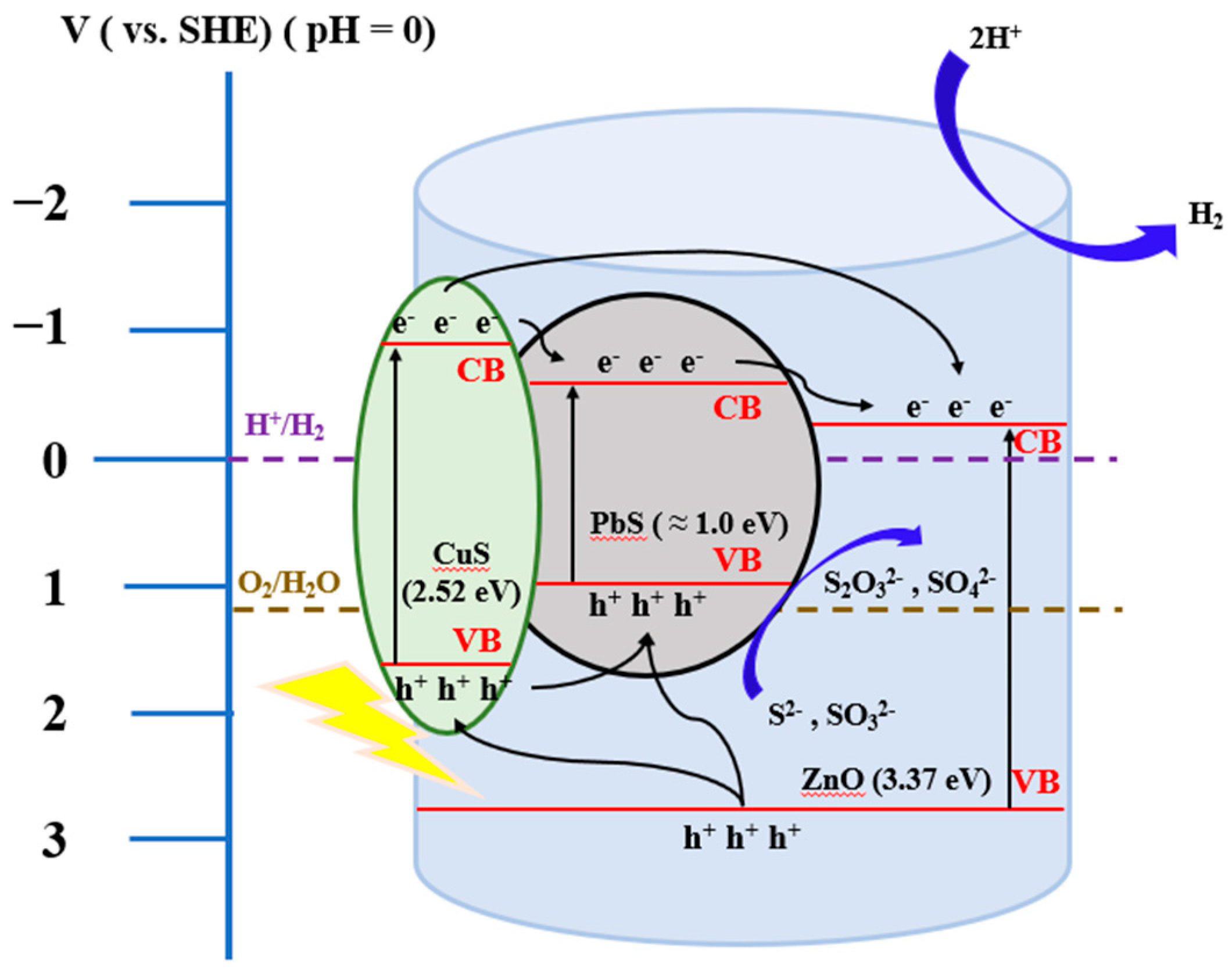
An appropriate amount of Pb(CH3COO)2∙2H2O and Cu(CH3COO)2∙H2O was weighed and dissolved in DI water to form an acetate solution, which was then mixed with the ZnO photocatalyst powder synthesized above and stirred uniformly. Excess CH3CSNH2 (2.5 times the mixture of lead acetate and copper acetate) was added at a rate of 1–2 mL/min, stirred for 2 h, and then ultrasonically shaken for 30 min. After completion of the reaction, 1 M NaOH was added to adjust the pH of the solution to 11, and the solution was poured into a Teflon-lined container, placed in an autoclave, and heated to 100, 130, 150, or 170 °C for 24 h via the hydrothermal method. After heating, the mixture was left to cool to room temperature, and the precipitate was washed several times with DI water and C2H5OH and freeze-dried for 8 h. After drying, the CuS/PbS/ZnO photocatalyst powder was obtained and stored in a sample bottle wrapped with aluminum foil to avoid exposure to external light. Figure 11 shows the bandgap correlation diagram of the prepared CuS/PbS/ZnO heterojunction photocatalyst.
3.4. The Degree of Recombination of Photocatalyst
The degree of recombination of the photocatalyst is the electron–hole recombination rate of the prepared photocatalyst, which is measured via fluorescence spectrometer photoluminescence (PL). When the photocatalyst is irradiated with a light source with a wavelength of 579 nm, the excited photocatalyst generates electrons in the conduction band, and then falls back to the conduction band to generate fluorescence. In this way, the recombination rate of the electron–hole pairs of the photocatalyst was judged by the fluorescence intensity of each sample.
3.5. Photocatalytic Hydrogen Production
The photocatalytic water splitting hydrogen production reactor system used in this study was a semi-open type. The simulated light source was a 300 W solar simulator, and an AM 1.5 G filter was installed as the illumination light source. The distance between the light source and the photocatalytic reactor was 20 cm. The main body of the reactor was made of light-transmitting quartz glass. There were four holes on the reactor, two of which were the inlet and outlet holes for helium gas, and two of which were the pressure detection hole and the sampling port. CuS/PbS/ZnO photocatalyst powder (50 mg) was placed in the reactor, and the photocatalytic reaction was carried out in pure water to study the effect of hydrogen production via water splitting. The results were compared those obtained by adding 0.25 M sacrificial reagent (mixed solution of Na2S and Na2SO3). After adding the 0.25 M sacrificial reagent (mixed solution of Na2S and Na2SO3) and allowing the photocatalytic reaction to proceed for 5 h, the solution was centrifuged at 6000 rpm to filter out the photocatalyst. Subsequently, under similar conditions, the water splitting experiment to produce hydrogen was repeated 10 times.
In the photocatalytic decomposition of water for hydrogen production, the gas in the reactor was extracted by a gas needle every hour and passed through a gas chromatograph (GC, YL Instrument 6500GC system) connected to a thermal conductivity detector (TCD) to analyze the hydrogen content. During the process, helium was used as the carrier gas, where the gas flow rate was 30 mL/min. The sample was injected into the injection port at a temperature of 180 °C; the column type was molecular-sieves, and the temperature was set at 60 °C. CuS/PbS/ZnO photocatalyst is used on organic compounds (such as a five-membered ring system), but it may be cracked due to high temperature in the process of illumination. However, it is believed that photocatalyst research can be carried out in the ring catalyst system in the future. [41].
4. Conclusions
CuS NPs and PbS QDs were successfully loaded onto ZnO photocatalysts by a hydrothermal method, and the resulting CuS/PbS/ZnO heterojunction photocatalyst was applied to photocatalytic hydrogen production under sunlight irradiation. The sulfide-loaded PbS QDs and CuS NPs on the ZnO photocatalyst enhanced the absorption of the photocatalyst in the near-infrared region to the visible light region. The quantum confinement effect of the sulfide QDs widened the bandgap of the photocatalyst, and indeed reduced electron–hole recombination, thus effectively improving the photocatalytic hydrogen production efficiency of the photocatalyst. The CuS/PbS/ZnO photocatalyst prepared at a hydrothermal temperature of 130 °C had better efficiency, where the hydrogen production amounted to 6654 μmol g−1 h−1 when a 0.25 M aqueous mixture of Na2S and Na2SO3 was added as a sacrificial reagent.
Author Contributions
W.-D.Y. conceived and designed the experiments; C.-C.K. performed the experiments; M.-H.C. and C.-W.H. analyzed the data; M.-H.C. wrote the paper. All authors have read and agreed to the published version of the manuscript.
Funding
The authors thank the Ministry of Science and Technology of Taiwan for financial support under grant no. MOST 110-2221-E-151-040.
Conflicts of Interest
The authors declare no conflict of interest.
References
- Hermesmann, M.; Müller, T.E. Green, Turquoise, Blue, or Grey? Environmentally Friendly Hydrogen Production in Transforming Energy Systems. Prog. Energy Combust. Sci. 2022, 90, 100996. [Google Scholar] [CrossRef]
- Okonkwo, P.C.; Barhoumi, E.M.; Mansir, I.B.; Emori, W.; Bhowmik, H. Effect of electrode material on the hydrogen production using a low-cost home-made alkaline electrolyzer. Vacuum 2022, 198, 110878. [Google Scholar] [CrossRef]
- Chang, C.J.; Lin, Y.G.; Chen, J.K.; Huang, C.Y.; Hsieh, S.C.; Wu, S.Y. Ionic liquid/surfactant-hydrothermal synthesis of dendritic PbS@CuS core-shell photocatalysts with improved photocatalytic performance. Appl. Surf. Sci. 2021, 546, 149106. [Google Scholar] [CrossRef]
- Frank, S.N.; Allen, J. Heterogeneous photocatalytic oxidation of cyanide and sulfite in aqueous solutions at semiconductor powders. J. Phys. Chem. 1977, 15, 1484–1488. [Google Scholar] [CrossRef]
- Chiarello, G.L.; Aguirre, M.H.; Selli, E. Hydrogen production by photocatalytic steam reforming of methanol on noble metal-modified TiO2. J. Catal. 2010, 20, 182–190. [Google Scholar] [CrossRef]
- Fujishima, A.; Honda, K. Electrochemical photolysis of water splitting at a semiconductor electrode. Nature 1972, 5358, 37–38. [Google Scholar] [CrossRef]
- Sun, L.; Koh, Z.Y. PbS quantum dots embedded in a ZnS dielectric matrix for bulk heterojunction solar cell applications. Adv. Mater. 2013, 33, 4598–4604. [Google Scholar] [CrossRef]
- Li, X.; Sun, Z.; Bao, Y.; Xia, X.; Tao, T.; Homewood, K.P.; Li, R.; Gao, Y. Comprehensively improved hydrogen sensing performance via constructing the facets homojunction in rutile TiO2 hierarchical structure. Sens. Actuators B 2022, 350, 130869. [Google Scholar] [CrossRef]
- Xu, Y.; Li, H.; Sun, B.; Qiao, P.; Ren, L.; Guohui, T.; Jiang, B.J.; Pan, K.; Zhou, W. Surface oxygen vacancy defect-promoted electron-hole separation for porous defective ZnO hexagonal plates and enhanced solar-driven photocatalytic performance. Chem. Eng. J. 2020, 379, 122295. [Google Scholar] [CrossRef]
- You, J.; Wang, L.; Bao, W.; Yan, A.; Guo, R. Synthesis and visible-light photocatalytic properties of BiOBr/CdS nanomaterials. J. Mater. Sci. 2021, 56, 6732–6744. [Google Scholar] [CrossRef]
- Abd-Rabboh, H.S.M.; Benaissa, M.; Hamdy, M.S.; Ahmed, M.A.; Glal, M. Synthesis of an efficient, and recyclable mesoporous BiVO4/TiO2 direct Z-scheme heterojunction by sonochemical route for photocatalytic hydrogen production and photodegradation of rhodamine B dye in the visible region. Opt. Mater. 2021, 114, 110761. [Google Scholar] [CrossRef]
- Tentu, R.D.; Basu, S. Photocatalytic water splitting for hydrogen production. Curr. Opin. Electrochem. 2017, 1, 56–62. [Google Scholar] [CrossRef]
- Sclafani, A.; Herrmann, J.M. Influence of metallic silver and of platinum-silver bimetallic deposits on the photocatalytic activity of titania (anatase and rutile) in organic and aqueous media. J. Photochem. Photobiol. A 1998, 113, 181–188. [Google Scholar] [CrossRef]
- Brezova, V.; Blazkova, A.; Karpinsky, L.; Ceppan, M. Phenol decomposition using Mn+/TiO2 photocatalysts supported by the sol-gel technique on glass fibres. J. Photochem. Photobiol. A 1997, 109, 177–183. [Google Scholar] [CrossRef]
- Yang, G.; Yan, W.; Zhang, Q.; Shen, S.; Dingd, S.J. One-dimensional CdS/ZnO core/shell nanofibers via single-spinneret electrospinning: Tunable morphology and efficient photocatalytic hydrogen production. Nanoscale 2013, 24, 12432–12439. [Google Scholar] [CrossRef]
- Goma, P.; Hachisuka, K.; Katsumata, H.; Suzuki, T.; Funasaka, K.; Kaneco, S. Photocatalytic hydrogen production with CuS/ZnO from aqueous Na2S + Na2SO3 solution. Int. J. Hydrogen Energy 2013, 38, 8625–8630. [Google Scholar]
- Zhao, X.; Feng, J.; Liu, J.; Lu, J.; Shi, W.; Yang, G.; Wang, G.; Feng, P.; Cheng, P. Metal-Organic Framework-Derived ZnO/ZnS Heteronanostructures for Efficient Visible-Light-Driven Photocatalytic Hydrogen Production. Adv.Sci. 2018, 4, 1700590. [Google Scholar] [CrossRef]
- Inoue, T.; Watanabe, T.; Fujishma, A.; Honda, K.I. Suppression of Surface Dissolution of CdS Photoanode by Reducing Agents. J. Electrochem. Soc. 1977, 124, 719. [Google Scholar] [CrossRef]
- Alivisatos, A.P. Semiconductor clusters, nanocrystals, and quantum dots. Science 1996, 271, 933–937. [Google Scholar] [CrossRef] [Green Version]
- Nandi, P.; Das, D. ZnO/CdS/CuS heterostructure: A suitable candidate for applications in visible-light photocatalysis. J. Phys. Chem. Solids 2022, 160, 110344. [Google Scholar] [CrossRef]
- Shi, X.F.; Xia, X.Y.; Cui, G.W.; Deng, N.; Zhao, Y.Q.; Zhuo, L.H.; Tang, B. Multiple exciton generation application of PbS quantum dots in ZnO@PbS/graphene oxide for enhanced photocatalytic activity. Appl. Catal. B 2015, 163, 123–128. [Google Scholar] [CrossRef]
- Liu, R.; Feng, S.Y.; Dong, C.D.; Tsai, K.C.; Yang, W.D. Enhancing hydrogen evolution of water splitting under solar spectra using Au/TiO2 heterojunction photocatalysts. Int. J. Hydrogen Energy 2021, 46, 28462–28473. [Google Scholar] [CrossRef]
- Wang, X.W.; Li, Q.C.; Xu, H.P.; Gan, L.; Ji, X.F.; Lui, H.; Zhang, R.G. CuS-modified ZnO rod/reduced graphene oxide/CdS heterostructure for efficient visible-light photocatalytic hydrogen generation. Int. J. Hydrogen Energy 2020, 45, 28394–28403. [Google Scholar] [CrossRef]
- Pahlevanpour, G.; Bashiri, H. Kinetic Monte Carlo simulation of hydrogen production from photocatalytic water splitting in the presence of methanol by 1 wt% Au/TiO2. Int. J. Hydrogen Energy 2022, 26, 12975–12987. [Google Scholar] [CrossRef]
- Patil, A.B.; Jadhav, B.D.; Bhoir, P. Optical band gap modification of Ce/ZnO for visible light photocatalytic H2 production from aqueous methanol solution. Opt. Mater. 2021, 121, 111503. [Google Scholar] [CrossRef]
- Conejeros, S.; Moreira Ide, P.; Alemany, P.; Canadell, E. Nature of Holes, Oxidation States, and Hypervalency in Covellite (CuS). Inorg. Chem. 2014, 53, 12402–12406. [Google Scholar] [CrossRef]
- Saranya, M.; Nirmala Grace, A. Hydrothermal synthesis of CuS nanostructures with different morphology. J. Nano Res. 2012, 18, 43–51. [Google Scholar] [CrossRef]
- Wei, J.; Wei, S.; Chang, N.; Wang, H.; Zhang, J.; Shao, W. Synthesis of PbS quantum dots/ZnO nanorods/Ag nanowires composite photocatalysts with enhanced photocatalytic activity. Mater. Lett. 2021, 285, 129130. [Google Scholar] [CrossRef]
- Yendrapati, T.P.; Gautam, A.; Bojja, S.; Pal, U. Formation of ZnO@CuS nanorods for efficient photocatalytic hydrogen generation. Sol. Energy 2020, 196, 540–548. [Google Scholar] [CrossRef]
- Guo, S.; Chen, W.; Li, M.; Wang, J.; Liu, F.; Cheng, J.P. Effect of reaction temperature on the amorphous-crystalline transition of copper cobalt sulfide for supercapacitors. Electrochim. Acta 2018, 271, 498–506. [Google Scholar] [CrossRef]
- Shalahuddin Al Ja’farawy, M.; Kusumandari; Purwanto, A.; Widiyandari, H. Carbon quantum dots supported zinc oxide (ZnO/CQDs) efficient photocatalyst for organic pollutant degradation-A systematic review. Environ. Nanotechnol. Monit. Manag. 2022, 18, 100681. [Google Scholar] [CrossRef]
- Liang, Y.; Novet, T.; Thorne, J.E.; Parkinson, B.A. Photosensitization of ZnO single crystal electrodes with PbS quantum dots. Phys. Status Solidi A 2014, 9, 1954–1959. [Google Scholar] [CrossRef]
- Guchhait, A.A.; Rath, K.; Pal, A.J. To make polymer: Quantum dot hybrid solar cells NIR-active by increasing diameter of PbS nanoparticles. Sol. Energy Mater. Sol. Cells 2011, 2, 651–656. [Google Scholar] [CrossRef]
- Hong, M.; Zhang, L.; Fang, H.; Feng, X.; Li, Z. Surface engineering of CdS quantum dots modified SiO2@C3N4 nanospheres for effective photocatalytic hydrogen evolution. Mater. Sci. Semicond. Process. 2021, 136, 106134. [Google Scholar] [CrossRef]
- He, B.; Bie, C.; Fei, X.; Cheng, B.; Yu, J.; Ho, W.; Al-Ghamdi, A.A.; Wageh, S. Enhancement in the photocatalytic H2 production activity of CdS NRs by Ag2S and NiS dual cocatalysts. Appl. Catal. B 2021, 288, 119994. [Google Scholar] [CrossRef]
- Chen, W.; Wang, Y.; Liu, S.; Gao, L.; Mao, L.; Fan, Z.; Shangguan, W.; Jiang, Z. Non-noble metal Cu as a cocatalyst on TiO2 nanorod for highly efficient photocatalytic hydrogen production. Appl. Surf. Sci. 2018, 445, 527–534. [Google Scholar] [CrossRef] [Green Version]
- Lee, S.; Chang, C.J. Recent Progress on Metal Sulfide Composite Nanomaterials for Photocatalytic Hydrogen Production. Catalysts 2019, 9, 457. [Google Scholar] [CrossRef] [Green Version]
- Wang, M.; Shen, S.; Li, L.; Tang, Z.; Yang, J. Effects of sacrificial reagents on photocatalytic hydrogen evolution over different photocatalysts. J. Mater. Sci. 2017, 9, 5155–5164. [Google Scholar] [CrossRef]
- Anuchai, S.; Phanichphant, S.; Tantraviwat, D.; Pluengphon, P.; Bovornratanaraks, T.; Inceesungvorn, B. Low temperature preparation of oxygen-deficient tin dioxide nanocrystals and a role of oxygen vacancy in photocatalytic activity improvement. J. Colloid Interface Sci. 2018, 512, 105–114. [Google Scholar] [CrossRef]
- Yavuz, C.; Erten-Ela, S. Solar light-responsive α-Fe2O3/CdS/g-C3N4 ternary photocatalyst for photocatalytic hydrogen production and photodegradation of methylene blue. J. Alloys Compd. 2022, 908, 164584. [Google Scholar] [CrossRef]
- Shiri, P. An overview on the copper-promoted synthesis of five-membered heterocyclic systems. Appl. Organomet. Chem. 2020, 34, 5. [Google Scholar] [CrossRef]
Figure 1.
TEM analysis of CuS/PbS/ZnO heterojunction photocatalyst. (a) Analytical images of CuS/PbS/ZnO photocatalyst, (b) image analysis of the lattice spacing for CuS NPs loaded onto ZnO, (c) image analysis of PbS QDs and ZnO lattice spacing, and (d) EDX analysis of CuS/PbS/ZnO photocatalyst.
Figure 1.
TEM analysis of CuS/PbS/ZnO heterojunction photocatalyst. (a) Analytical images of CuS/PbS/ZnO photocatalyst, (b) image analysis of the lattice spacing for CuS NPs loaded onto ZnO, (c) image analysis of PbS QDs and ZnO lattice spacing, and (d) EDX analysis of CuS/PbS/ZnO photocatalyst.
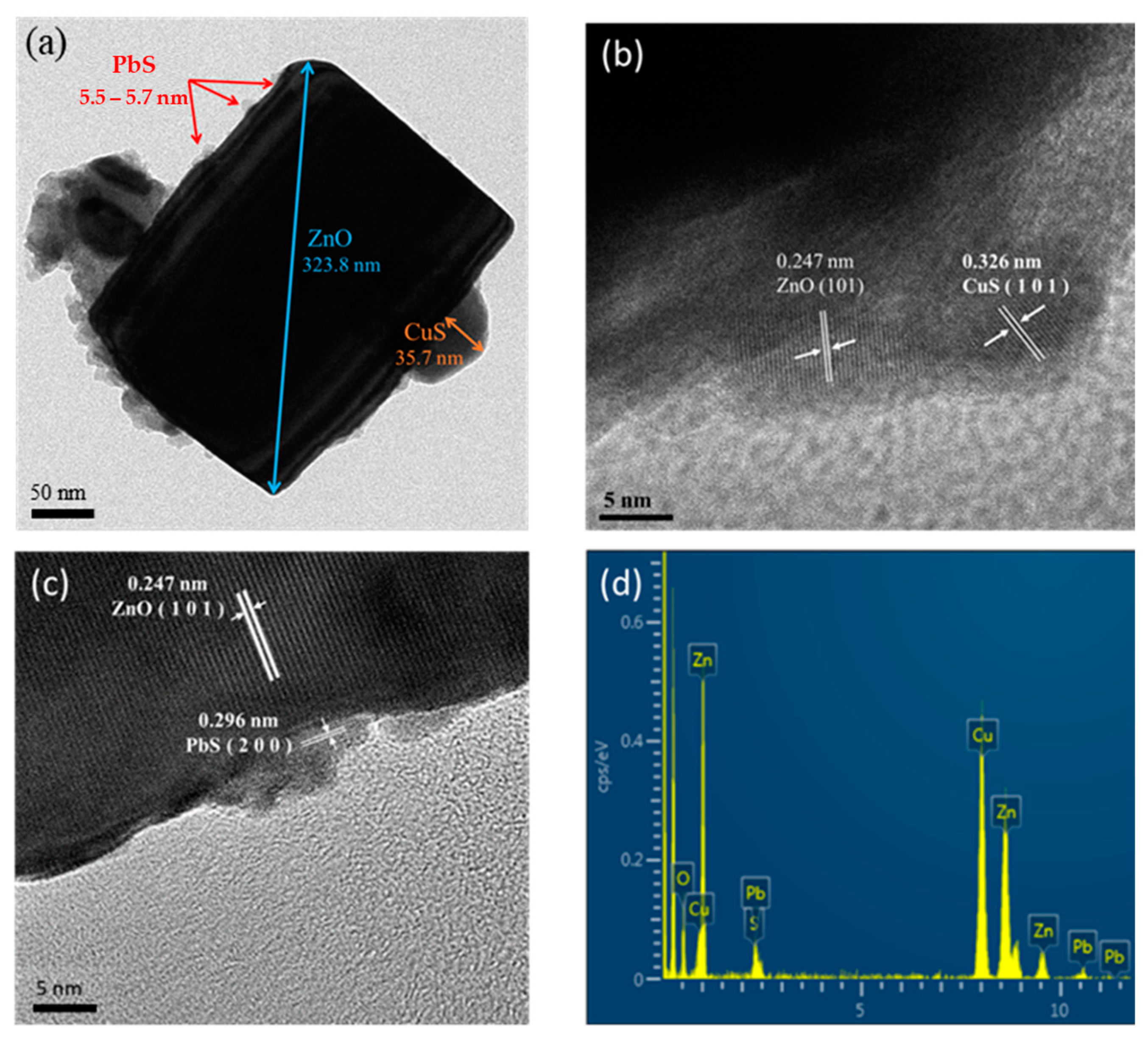
Figure 2.
XRD analysis of CuS/PbS/ZnO heterojunction photocatalysts prepared under different hydrothermal temperatures.
Figure 2.
XRD analysis of CuS/PbS/ZnO heterojunction photocatalysts prepared under different hydrothermal temperatures.

Figure 3.
UV-VIS-NIR spectra of CuS/PbS/ZnO photocatalysts prepared at various hydrothermal temperatures. Dotted lines indicate the maximum absorption wavelength of photocatalysts.
Figure 3.
UV-VIS-NIR spectra of CuS/PbS/ZnO photocatalysts prepared at various hydrothermal temperatures. Dotted lines indicate the maximum absorption wavelength of photocatalysts.

Figure 4.
Tauc plot of CuS/PbS/ZnO photocatalysts prepared at various hydrothermal temperatures.
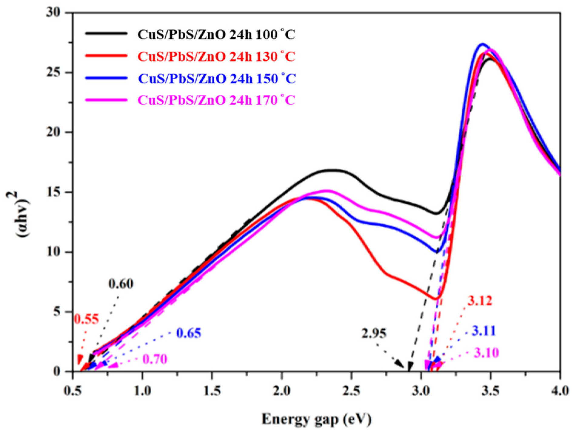
Figure 5.
PL spectra of the prepared photocatalysts at 579 nm as the excitation wavelength (a) Various sulfides supported on ZnO photocatalyst, and (b) CuS/PbS/ZnO photocatalysts prepared at different hydrothermal temperatures.
Figure 5.
PL spectra of the prepared photocatalysts at 579 nm as the excitation wavelength (a) Various sulfides supported on ZnO photocatalyst, and (b) CuS/PbS/ZnO photocatalysts prepared at different hydrothermal temperatures.

Figure 6.
Hydrogen production efficiency of respective photocatalysts in aqueous solution containing 0.25 M Na2S and Na2SO3 as sacrificial reagents. (a) Relationship between hydrogen production and time. (b) Hydrogen production rate in μmol g−1 h−1.
Figure 6.
Hydrogen production efficiency of respective photocatalysts in aqueous solution containing 0.25 M Na2S and Na2SO3 as sacrificial reagents. (a) Relationship between hydrogen production and time. (b) Hydrogen production rate in μmol g−1 h−1.

Figure 7.
Rate diagram of hydrogen production on PbS/ZnO loaded with different contents of CuS NPs.

Figure 8.
Analysis of hydrogen production in the presence of CuS/PbS/ZnO photocatalysts prepared at different hydrothermal temperatures. (a) No addition of Na2S and Na2SO3 mixed sacrificial reagent. (b) Addition of 0.25 M Na2S and Na2SO3 mixed sacrificial reagent.
Figure 8.
Analysis of hydrogen production in the presence of CuS/PbS/ZnO photocatalysts prepared at different hydrothermal temperatures. (a) No addition of Na2S and Na2SO3 mixed sacrificial reagent. (b) Addition of 0.25 M Na2S and Na2SO3 mixed sacrificial reagent.
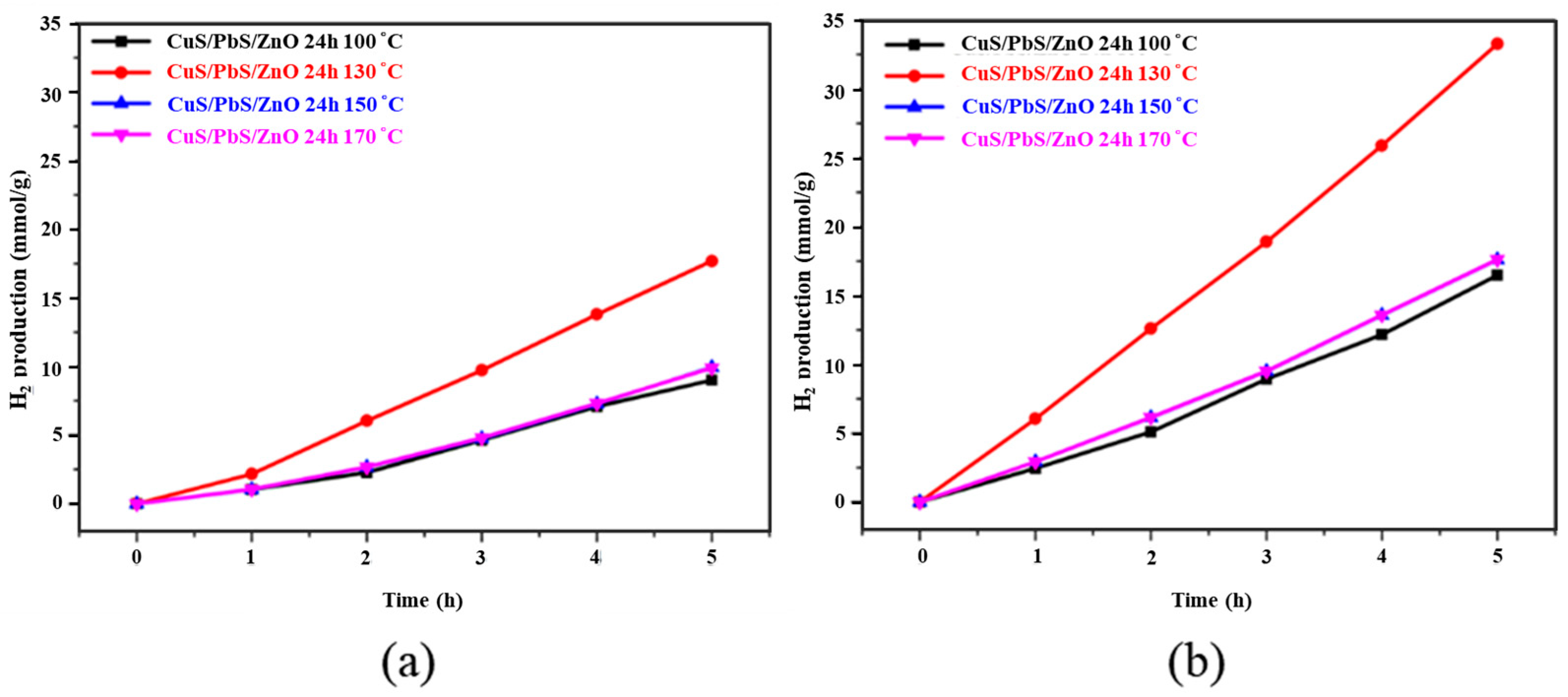
Figure 9.
SEM images of CuS/PbS/ZnO photocatalysts prepared at different hydrothermal temperatures. (a) 100 °C, (b) 130 °C, (c) 150 °C, and (d) 170 °C.
Figure 9.
SEM images of CuS/PbS/ZnO photocatalysts prepared at different hydrothermal temperatures. (a) 100 °C, (b) 130 °C, (c) 150 °C, and (d) 170 °C.
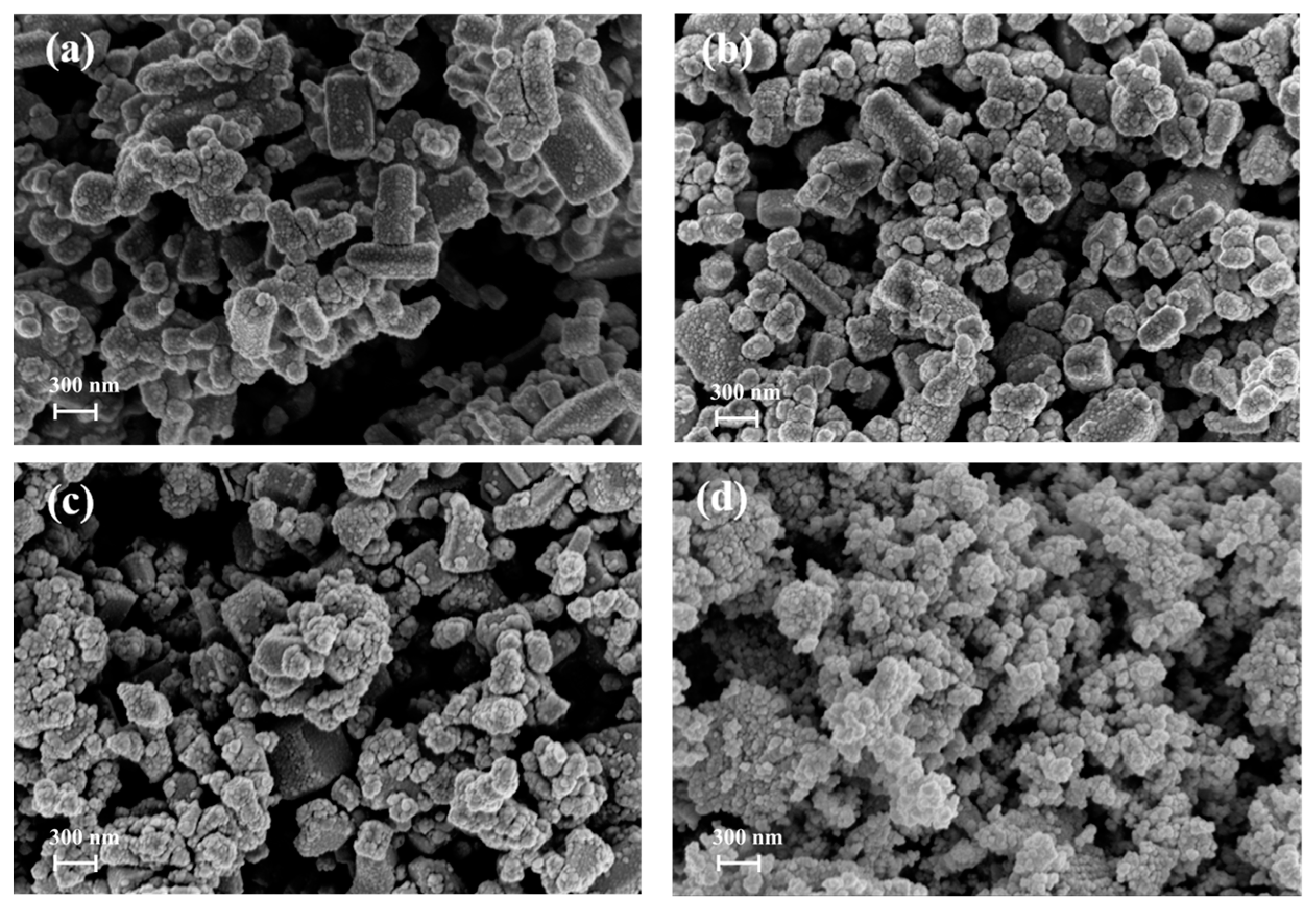
Figure 10.
Hydrogen production efficiency of CuS/PbS/ZnO photocatalyst prepared at a hydrothermal temperature of 130 °C, under photocatalytic reaction with solar simulator irradiation for 5 h.
Figure 10.
Hydrogen production efficiency of CuS/PbS/ZnO photocatalyst prepared at a hydrothermal temperature of 130 °C, under photocatalytic reaction with solar simulator irradiation for 5 h.

Figure 11.
Bandgap correlation diagram of the prepared CuS/PbS/ZnO heterojunction photocatalysts.

Table 1.
Monochromatic light source to the contribution of each component in the photocatalyst.
| Single Wave Length Light (nm) Photocatalyst | 300 | 350 | 400 | 600 | 800 | 1000 | 1400 | 1800 |
| Absorbance of the Photocatalysts (a.u.) | ||||||||
| ZnO | 0.408 | 0.615 | 0.000 | 0.000 | 0.000 | 0.000 | 0.000 | 0.000 |
| PbS/ZnO | 0.408 | 0.616 | 0.345 | 0.746 | 0.861 | 0.838 | 0.913 | 0.860 |
| CuS/ZnO | 0.408 | 0.625 | 0.665 | 0.754 | 0.627 | 0.627 | 0.587 | 0.546 |
| CuS/PbS/ZnO | 0.408 | 0.626 | 0.445 | 0.787 | 0.870 | 0.885 | 0.904 | 0.858 |
Table 2.
Evaluation of hydrogen production rate by single and heterojunction photocatalysts at monochromatic light.
Table 2.
Evaluation of hydrogen production rate by single and heterojunction photocatalysts at monochromatic light.
| Single Wave Length Light (nm) Photocatalyst | 350 | 600 | 800 | 1000 | 1200 |
| Hydrogen Production Rate (μmol min−1) | |||||
| ZnO | 224 | 0 | 0 | 0 | 0 |
| PbS | 0 | 212 | 234 | 188 | 201 |
| CuS | 0 | 197 | 220 | 207 | 194 |
| CuS/PbS/ZnO 24 h 130 °C | 271 | 346 | 375 | 394 | 446 |
Table 3.
Evaluation of single and heterojunction photocatalyst activities at monochromatic light.
| Single Wave Length Light (nm) Photocatalyst | 350 | 600 | 800 | 1000 | 1200 |
| Turnover Number, TON (min−1) | |||||
| ZnO | 4.48 | 0 | 0 | 0 | 0 |
| PbS | 0 | 4.24 | 4.68 | 3.76 | 4.02 |
| CuS | 0 | 3.94 | 4.40 | 4.14 | 3.88 |
| CuS/PbS/ZnO 24 h 130 °C | 5.42 | 6.92 | 7.50 | 7.88 | 8.92 |
Note: The photocatalyst amounts of CuS, PbS, ZnO and CuS/PbS/ZnO are all 50 μmole.
Table 4.
BET surface area, pore volume, and pore size of CuS/PbS/ZnO.
| Photocatalyst | BET Surface Area (m2 g−1) | Pore Volume (cm3 g−1) | Pore Size (nm) |
|---|---|---|---|
| CuS/PbS/ZnO 100 °C | 28.98 | 0.21 | 29.05 |
| CuS/PbS/ZnO 130 °C | 33.20 | 0.26 | 30.79 |
| CuS/PbS/ZnO 150 °C | 27.57 | 0.23 | 33.13 |
| CuS/PbS/ZnO 170 °C | 23.09 | 0.23 | 39.37 |
Publisher’s Note: MDPI stays neutral with regard to jurisdictional claims in published maps and institutional affiliations. |
© 2022 by the authors. Licensee MDPI, Basel, Switzerland. This article is an open access article distributed under the terms and conditions of the Creative Commons Attribution (CC BY) license (https://creativecommons.org/licenses/by/4.0/).
Share and Cite
MDPI and ACS Style
Chiu, M.-H.; Kuo, C.-C.; Huang, C.-W.; Yang, W.-D. Preparation of CuS/PbS/ZnO Heterojunction Photocatalyst for Application in Hydrogen Production. Catalysts 2022, 12, 1677. https://doi.org/10.3390/catal12121677
AMA Style
Chiu M-H, Kuo C-C, Huang C-W, Yang W-D. Preparation of CuS/PbS/ZnO Heterojunction Photocatalyst for Application in Hydrogen Production. Catalysts. 2022; 12(12):1677. https://doi.org/10.3390/catal12121677
Chicago/Turabian StyleChiu, Ming-Huan, Cheng-Ching Kuo, Chao-Wei Huang, and Wein-Duo Yang. 2022. "Preparation of CuS/PbS/ZnO Heterojunction Photocatalyst for Application in Hydrogen Production" Catalysts 12, no. 12: 1677. https://doi.org/10.3390/catal12121677
Note that from the first issue of 2016, this journal uses article numbers instead of page numbers. See further details here.