Article

Single-Phase θ-Fe3C Derived from Prussian Blue and Its Catalytic Application in Fischer-Tropsch Synthesis

1
State Key Laboratory of Coal Conversion, Institute of Coal Chemistry, Chinese Academy of Sciences, Taiyuan 030001, China
2
University of Chinese Academy of Sciences, Beijing 100049, China
3
College of Chemical Engineering and Technology, Taiyuan University of Technology, Taiyuan 030024, China
4
National Energy Center for Coal to Liquids, Synfuels China Co., Ltd., Huairou District, Beijing 101400, China
*
Author to whom correspondence should be addressed.
Catalysts 2022, 12(10), 1140; https://doi.org/10.3390/catal12101140
Submission received: 29 August 2022 / Revised: 19 September 2022 / Accepted: 27 September 2022 / Published: 29 September 2022
(This article belongs to the Topic Catalysis for Sustainable Chemistry and Energy)

Abstract

:
Elucidation of the intrinsic catalytic principle of iron carbides remains a substantial challenge in iron-catalyzed Fischer-Tropsch synthesis (FTS), due to possible interference from other Fe-containing species. Here, we propose a facile approach to synthesize single-phase θ-Fe3C via the pyrolysis of a molecularly defined Fe-C complex (Fe4[Fe(CN)6]3), thus affording close examination of its catalytic behavior during FTS. The crystal structure of prepared θ-Fe3C is unambiguously verified by combined XRD and MES measurement, demonstrating its single-phase nature. Strikingly, single-phase θ-Fe3C exhibited excellent selectivity to light olefins (77.8%) in the C2-C4 hydrocarbons with less than 10% CO2 formation in typical FTS conditions. This strategy further succeeds with promotion of Mn, evident for its wide-ranging compatibility for the promising industrial development of catalysts. This work offers a facile approach for oriented preparation of single-phase θ-Fe3C and provides an in-depth understanding of its intrinsic catalytic performance in FTS.

1. Introduction

Fischer-Tropsch synthesis (FTS) provides a premier route for production of ultra-clean transportation fuels and valuable chemicals upon conversion of syngas, which is readily available from biomass, coal, and shale gas [1,2,3,4]. The conversion of syngas into desirable products requires effective catalysts, which are primarily based on transition metal cobalt, ruthenium, and iron (Fe) [5,6,7,8,9]. In particular, Fe-based catalysts are widely used in industrial FTS processes, due to their low cost and tunability on product distribution, and thus gain enormous attention on its fundamental research [5,10,11,12,13]. Among these studies, a realization of the intrinsic role of active components was demonstrated to be essential for the rational design and development of effective catalysts [11,12,14]. However, given the fact that the working Fe-based FTS catalysts generally consist of complex species including both iron carbides, oxides, or metallic iron, complicated interactions between these species significantly impede the recognition of their individual contributions to the overall reaction [15]. To date, though iron carbides are generally believed to be active phases in FTS, it remains difficult to uncover their intrinsic working principle in the complex FTS reaction processes, with the interference of other Fe-containing species [16,17]. What is even more challenging is to precisely distinguish the individual contribution of iron carbide phases (such as χ-Fe5C2, ε-Fe2.2C, θ-Fe3C, etc.), as they usually coexist under practical FTS conditions [11,18,19].
Over past decades, tremendous effort has been devoted to synthesize single-phase iron carbide and study its catalytic application in FTS via excluding possible interference from iron carbides other than itself and other iron-containing components [13,20,21]. Despite the comprehensive understanding of the intrinsic catalytic behavior of χ-Fe5C2 and ε-Fe2.2C in FTS, relevant research about θ-Fe3C has not been reported yet [22,23]. In fact, θ-Fe3C was proposed to be more effective to suppress the formation of undesired CH4 with respect to χ-Fe5C2 and ε-Fe2.2C, as revealed by density functional theory calculations [24]. Recently, excellent selectivity for C2+ hydrocarbons (~90%) was realized on the θ-Fe3C-dominated Fe@C catalyst, advocating its potential in FTS application [12]. In addition, a large enhancement in reactivity towards valuable light olefins’ formation was also witnessed with increasing content of θ-Fe3C in a manganese-modified Fe3O4 microsphere catalyst [25]. Nonetheless, to the best of our knowledge, the definitive contribution of θ-Fe3C within the FTS process reported in the literature was extrapolated from a complex background containing multiple components. As such, it remains urgent and important to prepare single-phase θ-Fe3C and investigate its catalytic performance under FTS conditions.
Conventionally, iron carbides are obtained by direct carburization of metallic iron or iron oxides under a syngas atmosphere and high temperature, giving rise to a mixture of iron carbides and oxides due to segregation of Fe or carbon [11,26]. Instead of direct carburization, bottom-up strategies such as wet chemical synthesis or the pyrolysis of molecular precursors provide a powerful approach to synthesize transition metal carbides [22,27]. Particularly, the pyrolysis of molecularly defined precursors enables the preparation of size-controllable and homogenously distributed materials [12,22]. Inspired by these precedents, we propose to construct a ligand-chelated Fe-complex, followed by controllable pyrolysis to carburize Fe with decomposed carbon in the ligand, to prepare target θ-Fe3C with uniform spatial distribution of C and Fe atoms.
Combined characterization of X-ray diffraction (XRD) and 57Fe Mössbauer spectroscopy (MES) was used to verify the crystal structure of as-prepared θ-Fe3C and monitor the phase transition during the pyrolysis of precursors at different temperatures. The catalytic FTS performance of single-phase θ-Fe3C was carefully evaluated in typical conditions. We envision that this work will offer a useful approach to synthesis single-phase θ-Fe3C and further provide an in-depth understanding of its intrinsic catalytic performance in FTS, which will pave the road for the development of Fe-based FTS catalysts.

2. Results and Discussion

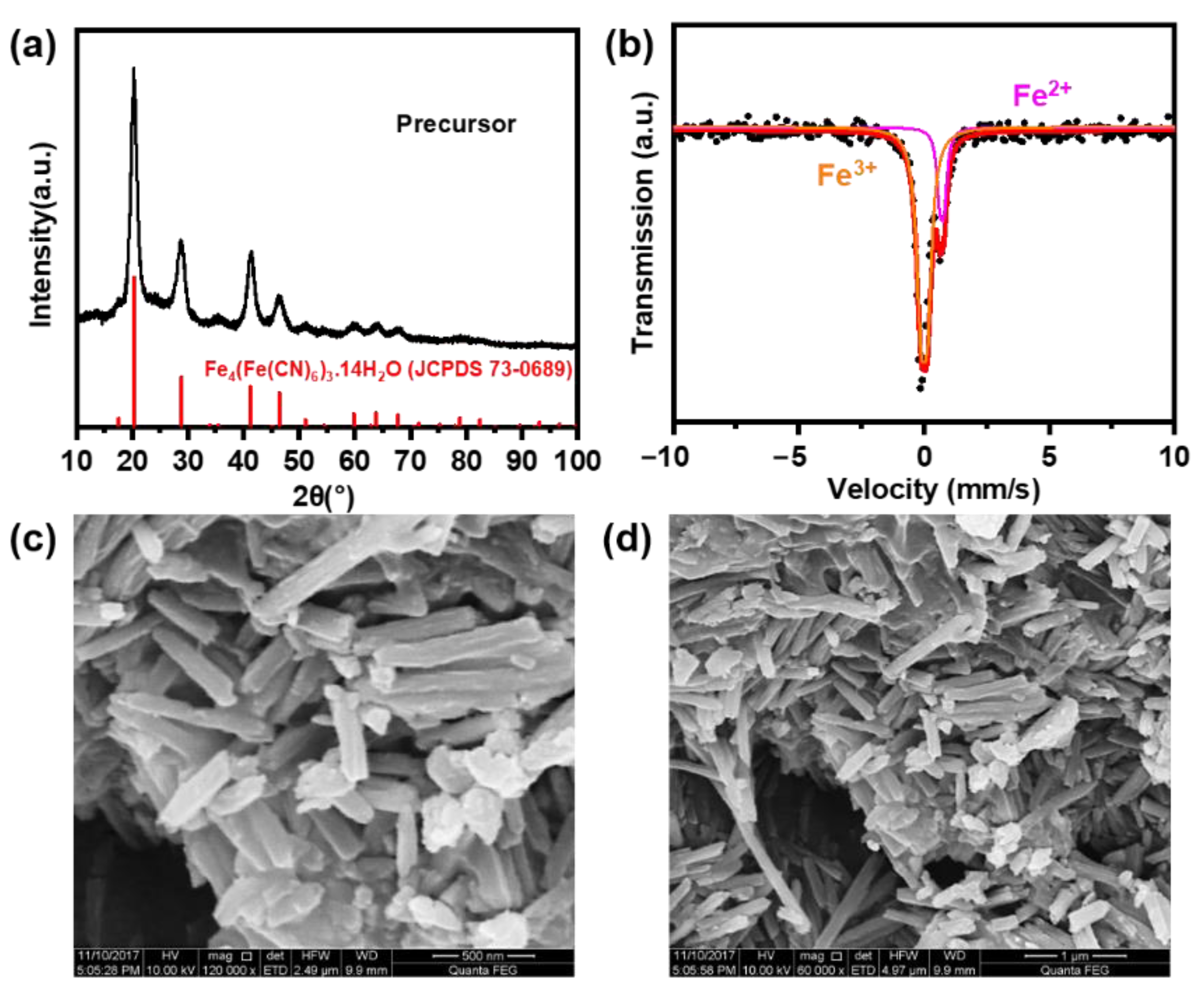
2.1. Structure and Morphology of the Precursor

The structures of the precursors were characterized by XRD and 57Fe MES, respectively. Figure 1a shows the XRD pattern of the precursor. All peaks in the pattern were attributed to Fe4[Fe(CN)6]3·14H2O (JCPDS No. 73-0689), indicating that the precursor has high crystallinity and a pure-phase Prussian blue analogue (PBA) structure. A uniform Fe-C chemical environment with approximately equal carbon chemical potential (μC) around each Fe atom was constructed in the precursor, which can provide favorable conditions for the formation of single-phase θ-Fe3C [23]. The MES spectra of the precursor is shown in Figure 1b and the corresponding Mössbauer parameters are shown in Table 1. The Mössbauer spectrum of the precursor was fitted with two doublets. The pink doublet corresponds to Fe2+ (IS = 0.72 mm/s, QS = 0.16 mm/s, 35.7%) and the orange doublet correspond to Fe3+ (IS = 0.00 mm/s, QS = −0.26 mm/s, 64.3%). To further investigate the morphology of the precursor, the precursor was characterized by SEM (Figure 1c,d). It can be clearly observed that precursors were in an extremely uniform rod shape.

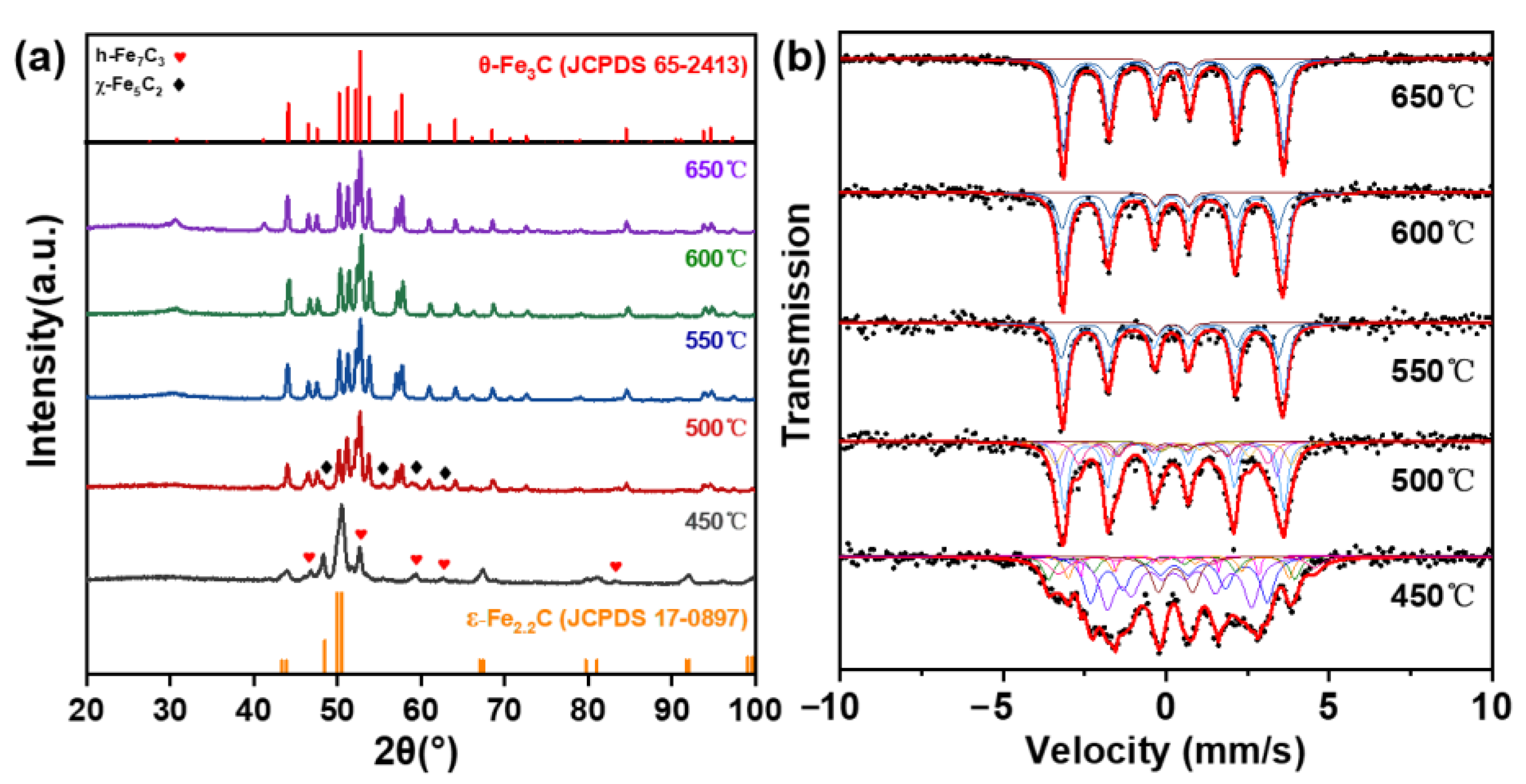
2.2. Synthesis of θ-Fe3C Catalyst

Pyrolysis temperature and atmosphere play important roles in controlling the phase formed. Theoretical studies showed that low μC is beneficial to the formation of θ-Fe3C, which can effectively inhibit the formation of other carbon-rich iron carbides (χ-Fe5C2, h-Fe7C3, ε-Fe2.2C, etc.) [23]. In addition, low μC can also avoid excessive carbon deposition on the sample surface. Therefore, N2 was selected as the pyrolysis atmosphere to synthesis the θ-Fe3C sample. θ-Fe3C is generally prepared at temperatures higher than 400 °C, according to previous reports [12,23,28,29,30]. In order to obtain a single-phase θ-Fe3C sample, pyrolysis temperatures over 400 °C (450 °C, 500 °C, 550 °C, 600 °C, and 650 °C) were attempted.
The phase identification and compositions of the prepared samples with different pyrolysis temperatures were analyzed by XRD and MES. The XRD patterns of the samples obtained at different temperatures are shown in Figure 2a. 57Fe MES is a powerful method for analyzing iron-containing phases, which can accurately identify and quantify amorphous or microcrystalline iron species in samples [31,32]. Figure 2b and Table 2 exhibit the MES patterns and the corresponding Mössbauer parameters of the samples obtained at different pyrolysis temperatures, respectively. It can be seen from Figure 2a that the XRD peaks of the sample obtained at 450 °C were mainly composed of the characteristic diffraction peaks of ε-Fe2.2C, and there were also peaks belonging to h-Fe7C3 at 46.4°, 52.6°, 59.4°, 62.7°, and 83.0°. Therefore, the phase composition of the sample obtained at 450 °C was mainly ε-Fe2.2C and a small amount of h-Fe7C3. Using MES analysis, it can be found that the content of ε-Fe2.2C in the sample was about 69.5%, and the contents of h-Fe7C3 and the Fe (spm) were 20.2% and 10.3%, respectively. The XRD peaks of the sample prepared at 500 °C consisted of the peaks corresponding to θ-Fe3C and χ-Fe5C2 (Figure 2a). The phase compositions of the sample pyrolyzed at 500 °C were mainly θ-Fe3C and χ-Fe5C2, and their contents were 55.0% and 40.8%, respectively (Figure 2b). The XRD patterns of the samples obtained at 550 °C, 600 °C, and 650 °C exhibited only the characteristic peaks of θ-Fe3C and a weak peak of graphitic carbon at 30.5°. In addition, the corresponding MES patterns also showed the typical sextet pattern of θ-Fe3C with a hyperfine magnetic field (Hhf) of 206–210 kOe. This indicates that the single-phase θ-Fe3C can be obtained by pyrolysis of the PBA at 550 °C, 600 °C, and 650 °C. Combined with MES analysis (Figure 2b and Table 2), we found that the contents of θ-Fe3C in the samples obtained at 550 °C, 600 °C, and 650 °C were 95.4%, 95.0%, and 93.9%, respectively. When the temperature was higher than 550 °C, the content of θ-Fe3C in the samples tended to decrease with the temperature increasing, which may have been caused by the escape of C at elevated temperatures. Therefore, the optimum temperature for preparing single-phase θ-Fe3C is 550 °C.

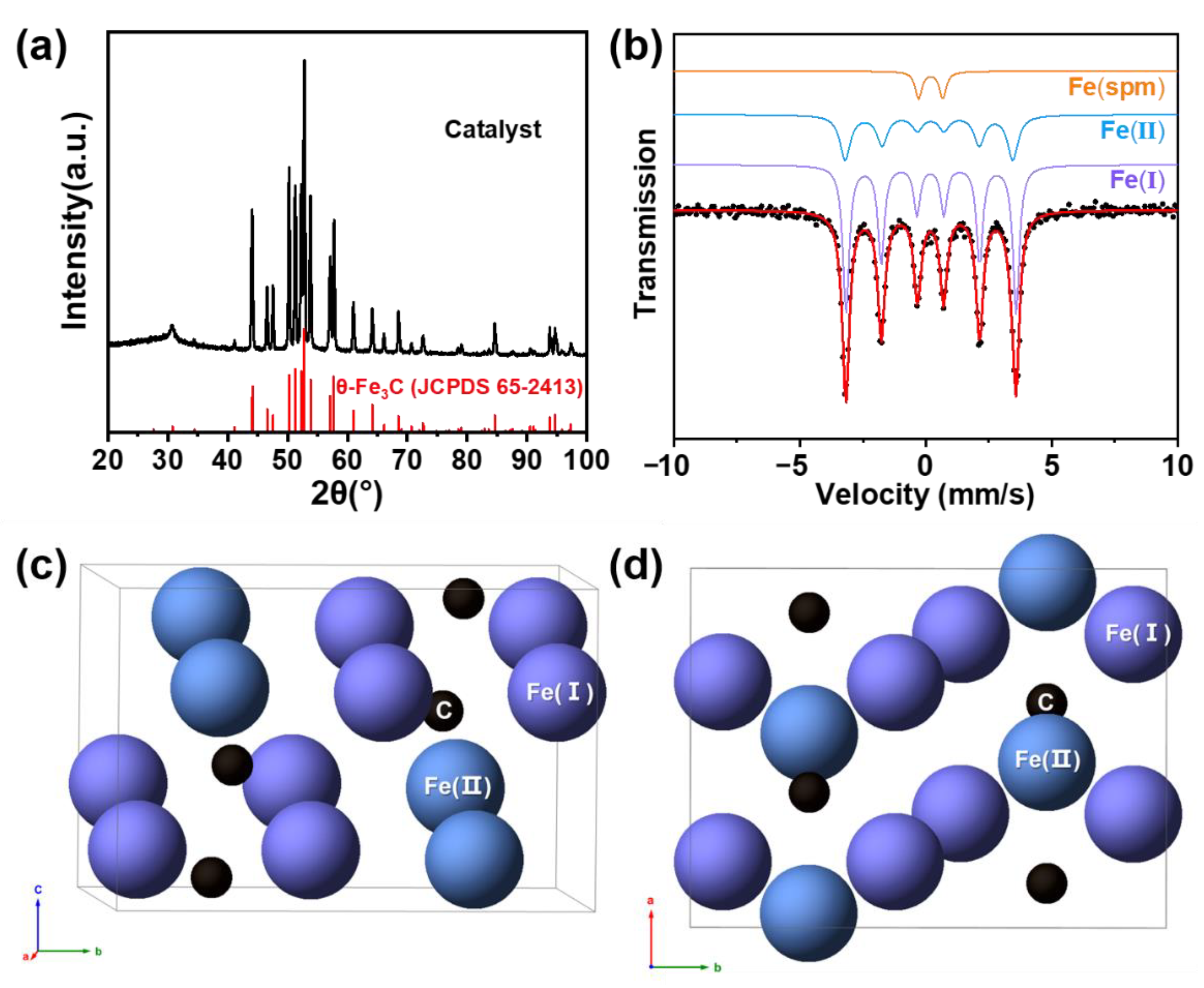
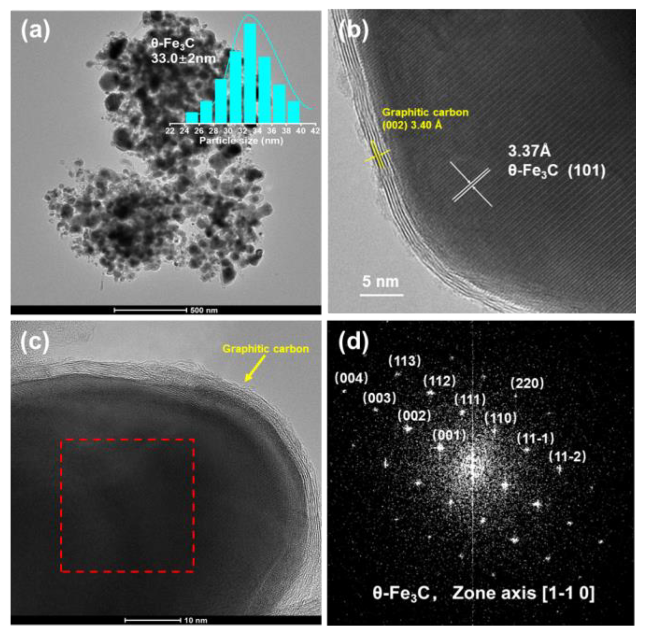
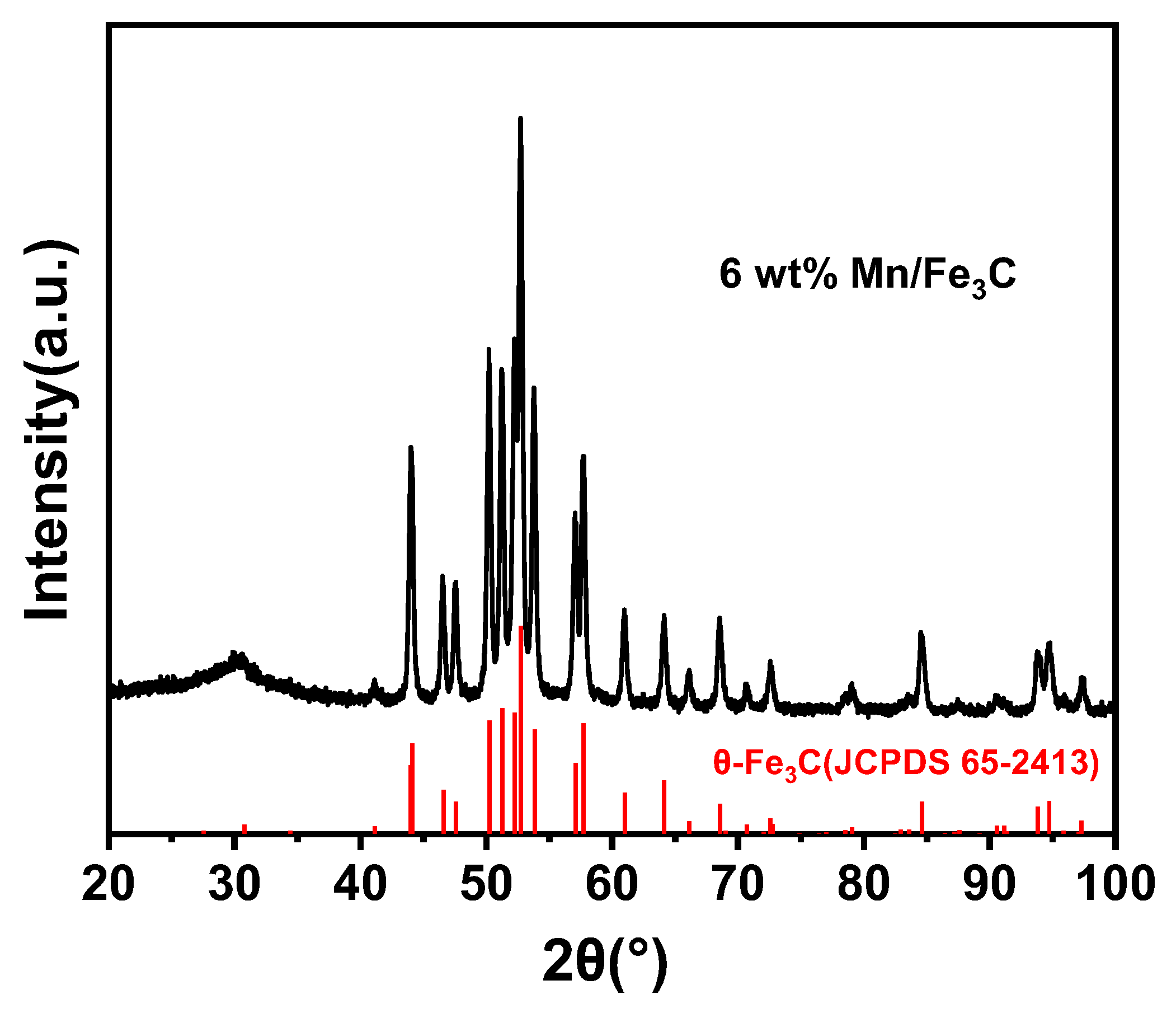
2.3. Structure and Morphology of the Prepared θ-Fe3C Sample

After optimizing the pyrolysis conditions, the sample pyrolyzed at 550 °C under N2 for 1 h was further characterized. The phase composition, crystal structure, and crystal size of the prepared sample were verified by XRD and MES. It can be seen from Figure 3a that the XRD pattern of the sample was in good agreement with the standard pure-phase θ-Fe3C (JCPDS No. 65-2413) and the graphic-carbon (JCPDS No. 41-1487), and no peaks corresponding to other iron-containing phases, indicating that the sample was single-phase θ-Fe3C. Estimated from the Scherrer equation, the average crystal size of the θ-Fe3C sample was 32.3 nm. Figure 3b shows the MES spectrum of the θ-Fe3C sample measured at room temperature and Table 3 is the corresponding Mössbauer parameters. The Mössbauer spectrum was fitted with two sextets and one doublet. The sextet (purple line) with a Hhf value of 210 kOe was assigned to Fe (I) with 12 neighboring iron atoms and the sextet (blue line) with Hhf value of 207 kOe was assigned to Fe (II) with 11 neighboring iron atoms [12,33]. The doublet (orange line) with the IS of 0.19 mm/s and QS of −0.96 mm/s was attributed to the poorly crystalline Fe species in the sample [12]. As shown in Figure 3c,d, the θ-Fe3C is described within the orthorhombic space group Pnma with 12 Fe and 4 C atoms per unit cell. The ideal structure of θ-Fe3C has two inequivalent crystallographic Fe-sites, named Fe (I) and Fe (II), with an atomic ratio of 2:1. The contents of Fe (I) and Fe (II) in the as-prepared θ-Fe3C sample were 63.5% and 31.9%, respectively, and their ratio was 1.99, which is very close to the ratio in the ideal structure. It shows that the prepared θ-Fe3C had good crystallinity. The absence of sextets with Hhf values of ~329 kOe assigned to metallic iron, and Hhf values of ~460, 490, and 510 kOe attributed to iron oxides indicates that neither metallic iron nor iron oxides were present [34,35]. This further proves that we have successfully synthesized a single-phase θ-Fe3C sample.
The morphology, particle size, and crystal structure of the sample were characterized by TEM. Figure 4 shows the TEM image of the θ-Fe3C sample. It can be seen from Figure 4a that the θ-Fe3C sample presented as random spheres with a particle size of 33.0 ± 2.0 nm, which was consistent with the result estimated by the Scherrer formula (32.3 nm). The θ-Fe3C particles were wrapped by a carbon shell (Figure 4b,c), which was consistent with the graphitic carbon peak at 30.5° in the XRD pattern. FFT images and interplanar distances of lattice fringes are also frequently used to identify different iron phases. As shown in Figure 4b, the interplanar distance of 3.37 Å in HRTEM corresponded to the (101) plane of θ-Fe3C. By comparing the FFT image of the sample with the simulated single-crystal diffraction pattern of θ-Fe3C, the square region in Figure 4c was identified as θ-Fe3C along with zone axis [1-10] (Figure 4d).

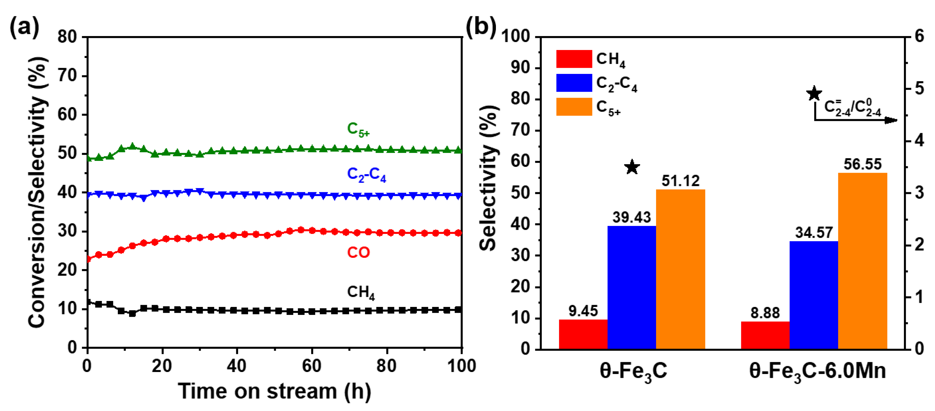
2.4. FTS Performances of the Prepared θ-Fe3C Sample

The most common iron carbides in FTS include ε-Fe2.2C, χ-Fe5C2, and θ-Fe3C [11,22,36]. ε-Fe2.2C and χ-Fe5C2 have been synthesized and demonstrated to be active in FTS [13,20,37,38]. There is still a lot of controversy about the role of θ-Fe3C in FTS. Although there are some reports on the role of θ-Fe3C in FTS, most of them are based on iron oxide or θ-Fe3C-dominated catalysts rather than single-phase θ-Fe3C catalysts. It is unreliable to draw conclusions about the role of θ-Fe3C based on these systems. Therefore, it is necessary to prepare a single-phase θ-Fe3C sample and apply it in FTS. The as-prepared θ-Fe3C sample was applied to FTS reaction under 2.0 MPa, 270 °C, and a H2/CO ratio of 2. Notably, the single-phase θ-Fe3C sample was not subjected to any pretreatment before the reaction, as the purpose of this work is to study the intrinsic catalytic performance of θ-Fe3C. Figure 5a shows the CO conversion and products selectivity of the θ-Fe3C sample, and the results are summarized in Table 4. As shown in Figure 5a, the CO conversion of the θ-Fe3C sample gradually increased from 24% to 30% in the first 40 h, and then kept stable at 30% over prolonged reaction times. With respect to the product distribution, the selectivity of CH4, C2-C4, C5+ (chains of five carbon atoms and longer) fluctuated slightly in the first 20 h, and remained stable at around 9.4%, 39.4%, and 51.2% after 20 h, respectively. The θ-Fe3C sample exhibited a stable CO conversion and product selectivity within 100 h of reaction, indicating the excellent catalytic stability of the as-prepared θ-Fe3C sample. This could be attributed to the core-shell structure of the sample, which not only improves the dispersion of the θ-Fe3C active phase, but also stabilizes the θ-Fe3C and protects it from agglomeration during the thermal reaction, which is crucial for the stability of the activity [12,39]. Overall, the single-phase θ-Fe3C sample exhibited excellent catalytic performance in terms of stability and selectivity to long-chain hydrocarbons (C5+), indicating that θ-Fe3C possesses superior C-C chain growth ability [12,40]. Furthermore, in the C2-C4 composition range, more valuable olefins accounted for 77.8% of the total C2-C4 products and for 30.6% of all hydrocarbon products, suggesting that θ-Fe3C is also an ideal catalyst for light olefins. It has been previously reported that θ-Fe3C can enhance the selectivity of light olefins [25]. The density functional theory (DFT) calculations showed that H2 can easily form a light-olefin-forming monomer (CH2 species) on Fe-C hybridization sites of θ-Fe3C, but the further hydrogenation of CH2 to CH3 and CH4 need to overcome relatively high barriers. This further illustrates that θ-Fe3C is intrinsically superior in producing light olefins [24,41].
Manganese is a commonly used promoter in FTS, which can improve the selectivity of desired products C5+ and reduce the selectivity of CH4 [5,42,43,44,45]. In order to verify the flexibility of the facile synthetic strategy for preparing the θ-Fe3C sample in this work, the Mn-doped θ-Fe3C sample (6 wt% Mn/Fe3C) was synthesized by the PBA-mediated synthesis strategy and then applied to the FTS. The XRD pattern of 6 wt% Mn/Fe3C is shown in Figure 6, and the texture properties of the samples are summarized in Table S1. It can be seen from Figure 6 that the XRD pattern of 6 wt% Mn/Fe3C was consistent with the pure-phase θ-Fe3C (JCPDS No. 65-2413), indicating that the main phase composition of the sample was θ-Fe3C. There was no peak attributed to Mn in the XRD pattern, which may be due to the high dispersion and low content of Mn in the sample. As shown in Table S1, the average crystallite size of the 6 wt% Mn/Fe3C sample (30.9 nm) was smaller than that of the θ-Fe3C sample (32.3 nm) and the surface area of the 6 wt% Mn/Fe3C sample (142 m2/g) was significantly larger than that of the θ-Fe3C sample (81 m2/g). It can be concluded that Mn can enhance the dispersion and favor smaller particles. This was attributed to the stabilization effect caused by the migration of Mn to the surface of the iron particles during the pyrolysis of the precursor (Figure S3). This was consistent with the report that Mn, serving as a structural promoter, improved the dispersion of iron particles, reduced the crystallite size of iron species, and increased the surface area of the catalysts [44,46,47]. The crystallite size of the 6 wt% Mn/Fe3C sample was only slightly reduced, which may be caused by the low content and insufficient dispersion of Mn in the sample [44,46,47,48]. Figure S6 shows the CO conversion and product selectivity of the 6 wt% Mn/Fe3C sample with the time on stream. At the initial state of reaction, compared with that of the θ-Fe3C sample, the higher CO conversion of the 6 wt% Mn/Fe3C sample may have been caused by the more active site provided by a larger surface area. However, under the syngas atmosphere, Mn was constantly separated from the iron particles and enriched on the surface of the iron particles, covering part of the active site of the catalyst [44]. As a result, the CO conversion (21.5%) of the 6 wt% Mn/Fe3C sample was lower than that of the single-phase θ-Fe3C (30%) when the reaction reached the steady state. Therefore, the doping of Mn decreased the activity of the catalyst, which was also observed in previous reports [46,47,49]. Although Mn reduces the activity of the catalyst, it can form an interaction with iron on the surface to improve the selectivity of the catalyst. The performance of the 6 wt% Mn/Fe3C sample is summarized in Figure 5b and Table 4. The 6 wt% Mn/Fe3C sample exhibited a good C5+ hydrocarbon selectivity of 56.6% and CH4 selectivity of 8.8%. Furthermore, the ratio of olefins to alkanes reached 4.9 in the C2-C4 hydrocarbon. Compared with the θ-Fe3C sample, the 6 wt% Mn/Fe3C sample showed a lower methane selectivity, and a higher C5+ selectivity and ratio of olefins to alkanes (C2-C4). In the FTS reaction, products’ distribution depends on the competition between surface carbon hydrogenation and C-C coupling [50,51,52]. The addition of Mn can promote C-C coupling and inhibit the hydrogenation process, thereby increasing the selectivity of long-chain hydrocarbons (C5+) and reducing the selectivity of light hydrocarbons (CH4 and C2-C4). The hydrogenation process is inhibited by Mn, which reduces the selectivity of C2-C4 alkanes and improves the selectivity of C2-C4 alkenes, thereby increasing the ratio of olefins to alkanes (C2-C4). Therefore, the addition of Mn further improves the θ-Fe3C selectivity to C5+ and reduces the selectivity to CH4. An improvement in products’ distribution has been achieved with promotion of Mn, demonstrating the versatile tunability of the molecularly defined complex pyrolysis strategy that might be applied in practical contexts.

3. Materials and Methods

3.1. Sample Preparation

To prepare single-phase iron carbide, we modified the procedure reported by Li et al. to synthesize the organometallic precursors with a single-metal Prussian blue analogue (PBA) structure [53]. The precursors (Fe3[Fe(CN)6]·nH2O) were prepared by the reaction of FeCl2·4H2O (Macklin, 99.95%, Shanghai, China) with K3[Fe(CN)6] (Macklin, 99.95%) in an aqueous Polyvinylpyrrolidone (PVP) solution. Typically, 6.0 g PVP (Alfa Aesar, M.W. 1,300,000, Waltham, MA, USA) was dissolved in 200 mL deionized water, and 8.95 g FeCl2·4H2O was added. Then, 200 mL aqueous K3[Fe(CN)6] solution (5 mmol/L) was slowly added into the above solution under vigorous stirring. The resulting dark-blue colloid solution was stirred for a further 0.5 h and aged under dark conditions for 20 h. The obtained precipitates were centrifuged and washed three times with a mixture of ethanol and deionized water, and then dried for 20 h in an oven at 60 °C. Similarly, the MnxFe3−x[Fe(CN)6]·nH2O was synthesized by reaction of FeCl2·4H2O and Mn(NO3)2·4H2O (Aladdin, 99.9%, Beijing, China) with K3[Fe(CN)6] in aqueous PVP solution. To obtain the Fe3C and Mn doped Fe3C catalysts, the obtained Fe3[Fe(CN)6]·nH2O and MnxFe3−x[Fe(CN)6]·nH2O were pyrolyzed at the desired temperature for 1 h under N2, respectively.

3.2. Sample Characterization

X-ray diffraction (XRD) was measured in a D8 powder diffractometer (Bruker, karlsruhe, Germany) using Co Kα radiation (λ = 0.179 nm) at 35 kV and 40 mA. A continuous mode was used with a scan step of 0.04° and retention time of 0.4 s in the range of 10–100° for precursors and 20–100° for catalysts. Mossbauer spectroscopy (MES) was obtained in an MR-351 constant-acceleration Mossbauer spectrometer (FAST, Esslingen, Germany) driven with a triangular reference signal at room temperature. The radioactive source was 57Co dispersed in a Rh medium. Data analysis was conducted using the MossWinn 4.0 software package. The velocity was calibrated by α-Fe foil, and the isomer shift (IS) value was referenced to α-Fe. A scanning electron microscopy (SEM) experiment was conducted on FEI 400 Quanta FEG equipment. A transmission electron microscopy (TEM) experiment was conducted on a TalosTM 200A (FEI, Portland, OR, USA) electron microscope operated at 200 kV. We dropped the samples dispersed in ethanol by sonication on the copper grid with porous carbon film, and then irradiated the sample with an infrared lamp for 20 min before testing. N2 physical adsorption measurement was conducted on Micromeritics ASAP 2420 equipment (Micromeritics, Norcross, GA, USA) at −196 °C. Before analysis, the catalyst was degassed under vacuum at 350 °C for 8 h. The metal concentration of the catalyst was analyzed by inductively coupled plasma-atomic emission spectrometry, and the data were collected and recorded on the Optima 2100D spectrometer (PerkinElmer, Waltham, MA, USA).

3.3. FTS Test

The FTS tests were performed on a stainless-steel fixed bed reactor with an isothermal bed length of 5 cm. An amount of 0.5 g catalyst (40–60 mesh) was loaded in the isothermal zone of the reactor and the remaining volume was filled with SiC particles of 60–80 mesh. The reactor system pressure was regulated to 2.0 MPa with syngas (H2/CO = 2) at a weight hourly space velocity (WHSV) of 5000 mL/g/h. The solid and liquid phase products were collected by hot trap (160 °C) and a cold trap (0 °C). The tail gas after reaction was divided into two routes, which were measured by wet gas flowmeter and analyzed by gas chromatograph, respectively (Model 6890N and 4890D, Agilent, Santa Clara, CA, USA). The used catalyst after reaction was taken out from the reactor protected by paraffins for further characterization. The mass balance in each test was above 95%.

4. Conclusions

In summary, we successfully synthesized single-phase θ-Fe3C via the pyrolysis of a molecularly defined (Fe4[Fe(CN)6]3) complex with homogeneous distribution of Fe and C atoms. XRD and MES were employed to verify the crystal structure of prepared θ-Fe3C, demonstrating its single-phase nature. On this basis, we carefully examined its catalytic performance in typical FTS conditions by excluding interference from other iron-containing species. Intriguingly, as-prepared single-phase θ-Fe3C showed outstanding light olefins selectivity of 77.8% in C2-C4 hydrocarbons while producing only 9.9% CO2 upon the overall products, outperforming single-phase Fe5C2 and Fe2.2C reported in the literature to date. In addition, improvement in producing olefins was achieved with the promotion of Mn, demonstrating its versatile tunability that might be applied in practical contexts. We anticipate that this work will enrich the understanding of the intrinsic catalytic contribution to the complex FTS process and pave the road for the development of Fe-based FTS catalysts.

Supplementary Materials

The following supporting information can be downloaded at: https://www.mdpi.com/article/10.3390/catal12101140/s1, Figure S1: SEM images of the θ-Fe3C sample; Figure S2: SEM images (a) precursor of 6 wt% Mn/Fe3C. (b,c) 6 wt% Mn/Fe3C sample; Figure S3: TEM elemental mapping images of 6 wt% Mn/Fe3C sample; Figure S4: N2 physisorption isotherm of θ-Fe3C sample; Figure S5: N2 physisorption isotherm of 6 wt% Mn/Fe3C sample; Figure S6: CO conversion and product selectivity of the 6 wt% Mn/Fe3C sample with the time on stream; Table S1: Textural properties, crystallite size, and manganese contents of samples.

Author Contributions

Conceptualization, W.Z. and X.W.; methodology, W.Z.; formal analysis, W.Z.; investigation, W.Z., X.L. and C.M.; writing—original draft preparation, W.Z.; writing—review and editing, W.Z. and X.W.; supervision, X.W.; project administration, X.W. and Y.Y.; funding acquisition, Y.L. All authors have read and agreed to the published version of the manuscript.

Funding

This work was supported by the National Natural Science Foundation of China (No. 21972157, No. 92045303, No. 21805301, and No. 22172183), CAS Project for Young Scientists in Basic Research (YSBR-005), Key R&D plan of the Beijing Municipal Science and Technology Commission (Z181100005118014), Key Research Program of Frontier Sciences CAS (ZDBS-LY-7007), and CAS Project for Internet Security and Information Technology (CAS-WX2021SF0110).

Data Availability Statement

This study did not report any data.

Acknowledgments

The authors are grateful for the facilities and financial support from Synfuels China, Co., Ltd. and the Beijing Advanced Innovation Center for Materials Genome Engineering.

Conflicts of Interest

The authors declare no conflict of interest.

References

  1. Bao, J.; Yang, G.; Yoneyama, Y.; Tsubaki, N. Significant Advances in C1 Catalysis: Highly Efficient Catalysts and Catalytic Reactions. ACS Catal. 2019, 9, 3026–3053. [Google Scholar] [CrossRef]
  2. Abello, S.; Montane, D. Exploring iron-based multifunctional catalysts for Fischer-Tropsch synthesis: A review. ChemSusChem 2011, 4, 1538–1556. [Google Scholar] [CrossRef] [PubMed]
  3. Dry, M.E. The Fischer-Tropsch process: 1950–2000. Catal. Today 2002, 71, 227–241. [Google Scholar] [CrossRef]
  4. Dry, M.E. Present and future applications of the Fischer-Tropsch process. Appl. Catal. A Gen. 2004, 276, 1–3. [Google Scholar] [CrossRef]
  5. Xu, Y.; Li, X.; Gao, J.; Wang, J.; Ma, G.; Wen, X.; Yang, Y.; Li, Y.; Ding, M. A hydrophobic FeMn@Si catalyst increases olefins from syngas by suppressing C1 by-products. Science 2021, 371, 610–613. [Google Scholar] [CrossRef] [PubMed]
  6. Torres Galvis, H.M.; Bitter, J.H.; Khare, C.B.; Ruitenbeek, M.; Dugulan, A.I.; de Jong, K.P. Supported iron nanoparticles as catalysts for sustainable production of lower olefins. Science 2012, 335, 835–838. [Google Scholar] [CrossRef]
  7. Zhong, L.; Yu, F.; An, Y.; Zhao, Y.; Sun, Y.; Li, Z.; Lin, T.; Lin, Y.; Qi, X.; Dai, Y.; et al. Cobalt carbide nanoprisms for direct production of lower olefins from syngas. Nature 2016, 538, 84–87. [Google Scholar] [CrossRef]
  8. Zhang, Y.; Su, X.; Li, L.; Qi, H.; Yang, C.; Liu, W.; Pan, X.; Liu, X.; Yang, X.; Huang, Y.; et al. Ru/TiO2 Catalysts with Size-Dependent Metal/Support Interaction for Tunable Reactivity in Fischer-Tropsch Synthesis. ACS Catal. 2020, 10, 12967–12975. [Google Scholar] [CrossRef]
  9. Zhang, Y.; Yang, X.; Yang, X.; Duan, H.; Qi, H.; Su, Y.; Liang, B.; Tao, H.; Liu, B.; Chen, D.; et al. Tuning reactivity of Fischer-Tropsch synthesis by regulating TiOx overlayer over Ru/TiO2 nanocatalysts. Nat. Commun. 2020, 11, 3185. [Google Scholar] [CrossRef]
  10. Wang, D.; Chen, B.; Duan, X.; Chen, D.; Zhou, X. Iron-based Fischer-Tropsch synthesis of lower olefins: The nature of χ-Fe5C2 catalyst and why and how to introduce promoters. J. Energy Chem. 2016, 25, 911–916. [Google Scholar] [CrossRef]
  11. Chang, Q.; Zhang, C.; Liu, C.; Wei, Y.; Cheruvathur, A.V.; Dugulan, A.I.; Niemantsverdriet, J.W.; Liu, X.; He, Y.; Qing, M.; et al. Relationship between Iron Carbide Phases (ε-Fe2C, Fe7C3, and χ-Fe5C2) and Catalytic Performances of Fe/SiO2 Fischer–Tropsch Catalysts. ACS Catal. 2018, 8, 3304–3316. [Google Scholar] [CrossRef]
  12. Ma, C.; Zhang, W.; Chang, Q.; Wang, X.; Wang, H.; Chen, H.; Wei, Y.; Zhang, C.; Xiang, H.; Yang, Y.; et al. θ-Fe3C dominated Fe@C core–shell catalysts for Fischer-Tropsch synthesis: Roles of θ-Fe3C and carbon shell. J. Catal. 2021, 393, 238–246. [Google Scholar] [CrossRef]
  13. Yang, C.; Zhao, H.; Hou, Y.; Ma, D. Fe5C2 nanoparticles: A facile bromide-induced synthesis and as an active phase for Fischer-Tropsch synthesis. J. Am. Chem. Soc. 2012, 134, 15814–15821. [Google Scholar] [CrossRef]
  14. Yin, J.; Liu, X.; Liu, X.-W.; Wang, H.; Wan, H.; Wang, S.; Zhang, W.; Zhou, X.; Teng, B.-T.; Yang, Y.; et al. Theoretical exploration of intrinsic facet-dependent CH4 and C2 formation on Fe5C2 particle. Appl. Catal. B Environ. 2020, 278, 119308. [Google Scholar] [CrossRef]
  15. Opeyemi Otun, K.; Yao, Y.; Liu, X.; Hildebrandt, D. Synthesis, structure, and performance of carbide phases in Fischer-Tropsch synthesis: A critical review. Fuel 2021, 296, 120689. [Google Scholar] [CrossRef]
  16. Reymond, J. Changes in the surface structure and composition of an iron catalyst of reduced or unreduced Fe2O3 during the reaction of carbon monoxide and hydrogen. J. Catal. 1982, 75, 39–48. [Google Scholar] [CrossRef]
  17. Kuivila, C. Compositional aspects of iron Fischer-Tropsch catalysts: An XPS/reaction study. J. Catal. 1989, 118, 299–311. [Google Scholar] [CrossRef]
  18. Butt, J.B. Carbide phases on iron-based Fischer-Tropsch synthesis catalysts part I: Characterization studies. Catal. Lett. 1991, 7, 61–81. [Google Scholar] [CrossRef]
  19. Butt, J.B. Carbide phases on iron-based Fischer-Tropsch synthesis catalysts part II: Some reaction studies. Catal. Lett. 1991, 7, 83–105. [Google Scholar] [CrossRef]
  20. Xu, K.; Sun, B.; Lin, J.; Wen, W.; Pei, Y.; Yan, S.; Qiao, M.; Zhang, X.; Zong, B. Epsilon-Iron carbide as a low-temperature Fischer-Tropsch synthesis catalyst. Nat. Commun. 2014, 5, 5783. [Google Scholar] [CrossRef]
  21. Wezendonk, T.A.; Sun, X.; Dugulan, A.I.; van Hoof, A.J.F.; Hensen, E.J.M.; Kapteijn, F.; Gascon, J. Controlled formation of iron carbides and their performance in Fischer-Tropsch synthesis. J. Catal. 2018, 362, 106–117. [Google Scholar] [CrossRef]
  22. Santos, V.P.; Wezendonk, T.A.; Jaen, J.J.; Dugulan, A.I.; Nasalevich, M.A.; Islam, H.U.; Chojecki, A.; Sartipi, S.; Sun, X.; Hakeem, A.A.; et al. Metal organic framework-mediated synthesis of highly active and stable Fischer-Tropsch catalysts. Nat. Commun. 2015, 6, 6451. [Google Scholar] [CrossRef] [PubMed]
  23. Smit, E.D.; Cinquini, F.; Beale, A.M.; Safonova, O.V.; Beek, W.V.; Sautet, P.; Weckhuysen, B.M. Stability and Reactivity of ε-χ-θ Iron Carbide Catalyst Phases in Fischer-Tropsch Synthesis: Controlling μc. J. Am. Chem. Soc. 2010, 132, 14928–14941. [Google Scholar] [CrossRef] [PubMed]
  24. Huo, C.F.; Li, Y.W.; Wang, J.; Jiao, H. Insight into CH4 formation in iron-catalyzed Fischer-Tropsch synthesis. J. Am. Chem. Soc. 2009, 131, 14713–14721. [Google Scholar] [CrossRef] [PubMed]
  25. Liu, Y.; Chen, J.-F.; Bao, J.; Zhang, Y. Manganese-Modified Fe3O4 Microsphere Catalyst with Effective Active Phase of Forming Light Olefins from Syngas. ACS Catal. 2015, 5, 3905–3909. [Google Scholar] [CrossRef]
  26. Niu, L.; Liu, X.; Wen, X.; Yang, Y.; Xu, J.; Li, Y. Effect of potassium promoter on phase transformation during H2 pretreatment of a Fe2O3 Fischer Tropsch synthesis catalyst precursor. Catal. Today 2020, 343, 101–111. [Google Scholar] [CrossRef]
  27. An, B.; Cheng, K.; Wang, C.; Wang, Y.; Lin, W. Pyrolysis of Metal–Organic Frameworks to Fe3O4@Fe5C2 Core–Shell Nanoparticles for Fischer-Tropsch Synthesis. ACS Catal. 2016, 6, 3610–3618. [Google Scholar] [CrossRef]
  28. Wang, X.; Zhang, P.; Wang, W.; Lei, X.; Yang, H. Fe3C and Mn doped Fe3C nanoparticles: Synthesis, morphology and magnetic properties. RSC Adv. 2015, 5, 57828–57832. [Google Scholar] [CrossRef]
  29. Barman, B.K.; Nanda, K.K. Prussian blue as a single precursor for synthesis of Fe/Fe3C encapsulated N-doped graphitic nanostructures as bi-functional catalysts. Green Chem. 2016, 18, 427–432. [Google Scholar] [CrossRef]
  30. Wang, X.; Zhang, P.; Gao, J.; Chen, X.; Yang, H. Facile synthesis and magnetic properties of Fe3C/C nanoparticles via a sol-gel process. Dye. Pigment. 2015, 112, 305–310. [Google Scholar] [CrossRef]
  31. Niemantsverdriet, J.W.; Flipse, C.F.J.; Van Der Kraan, A.M.; Van Loef, J.J. A Mössbauer study of surface effects on iron Fischer-Tropsch catalysts. Appl. Surf. Sci. 1982, 10, 302–313. [Google Scholar] [CrossRef]
  32. Phillips, J. Application of M¨ossbauer spectroscopy for the characterization of iron-containing catalysts. Hyperfine Interact. 1998, 111, 3–16. [Google Scholar] [CrossRef]
  33. Liu, X.W.; Zhao, S.; Meng, Y.; Peng, Q.; Dearden, A.K.; Huo, C.F.; Yang, Y.; Li, Y.W.; Wen, X.D. Mossbauer Spectroscopy of Iron Carbides: From Prediction to Experimental Confirmation. Sci. Rep. 2016, 6, 26184. [Google Scholar] [CrossRef] [PubMed]
  34. Lyubutin, I.S.; Lin, C.R.; Korzhetskiy, Y.V.; Dmitrieva, T.V.; Chiang, R.K. Mössbauer spectroscopy and magnetic properties of hematite/magnetite nanocomposites. J. Appl. Phys. 2009, 106, 034311. [Google Scholar] [CrossRef]
  35. Bukur, D.B.; Okabe, K.; Rosynek, M.P.; Li, C.P.; Wang, D.J.; Rao, K.R.P.M.; Huffman, G.P. Activation Studies with a Precipitated Iron Catalyst for Fischer-Tropsch Synthesis. J. Catal. 1995, 155, 353–365. [Google Scholar] [CrossRef]
  36. Datye, A.K.; Jin, Y.; Mansker, L.; Motjope, R.T.; Dlamini, T.H.; Coville, N.J. The nature of the active phase in iron Fischer-Tropsch catalysts. Stud. Surf. Sci. Catal. 2000, 130, 1139–1144. [Google Scholar]
  37. Hong, S.Y.; Chun, D.H.; Yang, J.I.; Jung, H.; Lee, H.T.; Hong, S.; Jang, S.; Lim, J.T.; Kim, C.S.; Park, J.C. A new synthesis of carbon encapsulated Fe5C2 nanoparticles for high-temperature Fischer-Tropsch synthesis. Nanoscale 2015, 7, 16616–16620. [Google Scholar] [CrossRef]
  38. Wang, P.; Chen, W.; Chiang, F.K.; Dugulan, A.I.; Song, Y.; Pestman, R.; Zhang, K.; Yao, J.; Feng, B.; Miao, P.; et al. Synthesis of stable and low-CO2 selective epsilon-iron carbide Fischer-Tropsch catalysts. Sci. Adv. 2018, 4, eaau2947. [Google Scholar] [CrossRef]
  39. Yu, G.; Sun, B.; Pei, Y.; Xie, S.; Yan, S.; Qiao, M.; Fan, K.; Zhang, X.; Zong, B. FexOy@C spheres as an excellent catalyst for Fischer-Tropsch synthesis. J. Am. Chem. Soc. 2010, 132, 935–937. [Google Scholar] [CrossRef]
  40. Zhang, Q.; Gu, J.; Chen, J.; Qiu, S.; Wang, T. Facile fabrication of porous Fe@C nanohybrids from natural magnetite as excellent Fischer-Tropsch catalysts. Chem. Commun. 2020, 56, 4523–4526. [Google Scholar] [CrossRef]
  41. Liu, Y.; Lu, F.; Tang, Y.; Liu, M.; Tao, F.F.; Zhang, Y. Effects of initial crystal structure of Fe2O3 and Mn promoter on effective active phase for syngas to light olefins. Appl. Catal. B Environ. 2020, 261, 118219. [Google Scholar] [CrossRef]
  42. Li, J.; Wu, L.; Zhang, S.; Wen, J.; Liu, M.; Wang, C.; Li, X. The promotional effect of Mn on Fe-based Fischer-Tropsch catalysts for the synthesis of C5+ hydrocarbons. Sustain. Energy Fuels 2019, 3, 219–226. [Google Scholar] [CrossRef]
  43. Zhang, Y.; Ma, L.; Wang, T.; Li, X. MnO2 coated Fe2O3 spindles designed for production of C5+ hydrocarbons in Fischer-Tropsch synthesis. Fuel 2016, 177, 197–205. [Google Scholar] [CrossRef]
  44. Dad, M.; Fredriksson, H.O.A.; Van de Loosdrecht, J.; Thüne, P.C.; Niemantsverdriet, J.W. Stabilization of iron by manganese promoters in uniform bimetallic FeMn Fischer–Tropsch model catalysts prepared from colloidal nanoparticles. Catal. Struct. React. 2015, 1, 101–109. [Google Scholar] [CrossRef]
  45. Das, D.; Ravichandran, G.; Chakrabarty, D.K. Conversion of syngas to light olefins over silicalite-1 supported iron and cobalt catalysts: Effect of manganese addition. Catal. Today 1997, 36, 285–293. [Google Scholar] [CrossRef]
  46. Tao, Z.; Yang, Y.; Wan, H.; Li, T.; An, X.; Xiang, H.; Li, Y. Effect of manganese on a potassium-promoted iron-based Fischer-Tropsch synthesis catalyst. Catal. Lett. 2007, 114, 161–168. [Google Scholar] [CrossRef]
  47. Tao, Z.; Yang, Y.; Zhang, C.; Li, T.; Ding, M.; Xiang, H.; Li, Y. Study of Manganese Promoter on a Precipitated Iron-Based Catalyst for Fischer-Tropsch Synthesis. J. Nat. Gas Chem. 2007, 16, 278–285. [Google Scholar] [CrossRef]
  48. Campos, A.; Lohitharn, N.; Roy, A.; Lotero, E.; Goodwin, J.G.; Spivey, J.J. An activity and XANES study of Mn-promoted, Fe-based Fischer–Tropsch catalysts. Appl. Catal. A Gen. 2010, 375, 12–16. [Google Scholar] [CrossRef]
  49. Zhang, Y.; Wang, T.; Ma, L.; Shi, N.; Zhou, D.; Li, X. Promotional effects of Mn on SiO2-encapsulated iron-based spindles for catalytic production of liquid hydrocarbons. J. Catal. 2017, 350, 41–47. [Google Scholar] [CrossRef]
  50. Li, J.; Cheng, X.; Zhang, C.; Yang, Y.; Li, Y. Effects of alkali on iron-based catalysts for Fischer-Tropsch synthesis: CO chemisorptions study. J. Mol. Catal. A Chem. 2015, 396, 174–180. [Google Scholar] [CrossRef]
  51. Wang, S.; Yin, Q.; Guo, J.; Ru, B.; Zhu, L. Improved Fischer–Tropsch synthesis for gasoline over Ru, Ni promoted Co/HZSM-5 catalysts. Fuel 2013, 108, 597–603. [Google Scholar] [CrossRef]
  52. Govender, N.S.; Botes, F.G.; de Croon, M.H.J.M.; Schouten, J.C. Mechanistic pathway for methane formation over an iron-based catalyst. J. Catal. 2008, 260, 254–261. [Google Scholar] [CrossRef]
  53. Li, X.; Yuan, L.; Wang, J.; Jiang, L.; Rykov, A.I.; Nagy, D.L.; Bogdan, C.; Ahmed, M.A.; Zhu, K.; Sun, G.; et al. A “copolymer-co-morphology” conception for shape-controlled synthesis of Prussian blue analogues and as-derived spinel oxides. Nanoscale 2016, 8, 2333–2342. [Google Scholar] [CrossRef] [PubMed]
Figure 1. The structure and morphology of the precursor: (a) XRD pattern, (b) MES pattern measured at room temperature, (c,d) SEM images.
Catalysts 12 01140 g001
Figure 2. Phase identification of prepared samples with different pyrolysis temperatures. (a) XRD patterns. (b) MES patterns measured at room temperature.
Catalysts 12 01140 g002
Figure 3. The structural identification of prepared single-phase θ-Fe3C sample. (a) XRD pattern. (b) MES spectra measured at room temperature. (c,d) Crystal structure.
Catalysts 12 01140 g003
Figure 4. (ac) TEM images of the prepared single-phase θ-Fe3C sample. Inset histogram in (a) represents size distribution of θ-Fe3C particles. (d) FFT image of the corresponding selected area marked with red square in (c).
Catalysts 12 01140 g004
Figure 5. FTS performances of catalysts. (a) CO conversion and product selectivity of the θ-Fe3C sample with the time on stream. (b) Distributions of hydrocarbons over θ-Fe3C and 6 wt% Mn/Fe3C conducted at 270 °C, 2.0 MPa, H2/CO = 2, 5000 mL·h−1·g−1.
Catalysts 12 01140 g005
Figure 6. XRD pattern of 6 wt% Mn/Fe3C.
Catalysts 12 01140 g006
Table 1. MES parameters of the precursor.
PhasesArea (%)IS (mm/s)QS (mm/s)
Fe2+35.70.720.16
Fe3+64.30.00−0.26
Table 2. Mössbauer parameters of the catalysts pyrolyzed at different temperatures.
SamplesIS
(mm/s)
QS
(mm/s)
Hhf
(kOe)
Area
(%)
PhasesComposition
(%)
Sample-450 °C0.320.1416926.7ε-Fe2.2C (I)69.5
0.070.2123510.7ε-Fe2.2C (II)
0.320.1813832.1ε-Fe2.2C (III)
0.070.081703.6h-Fe7C3 (I)20.2
0.370.032118.3h-Fe7C3 (II)
−0.141.462468.3h-Fe7C3 (III)
0.291.05-10.3Fe (spm)10.3
Sample-500 °C0.220.120936.7θ-Fe3C (I)55.0
0.14−0.0920718.3θ-Fe3C (II)
0.37−0.2322516.3χ-Fe5C2 (I)40.8
0.240.0218016.3χ-Fe5C2 (II)
0.4−0.31058.2χ-Fe5C2 (III)
0.260.82-4.2Fe (spm)4.2
Sample-550 °C0.190.0721063.6θ-Fe3C (I)95.4
0.17−0.1220731.8θ-Fe3C (II)
0.18−0.92-4.6Fe (spm)4.6
Sample-600 °C0.190.0721063.3θ-Fe3C (I)95.0
0.17−0.1120631.7θ-Fe3C (II)
0.18−1.01-5.0Fe (spm)5.0
Sample-650 °C0.190.0321062.6θ-Fe3C (I)93.9
0.15−0.0720731.3θ-Fe3C (II)
0.19−0.96-6.1Fe (spm)6.1
Table 3. Mössbauer parameters of the θ-Fe3C sample.
PhaseArea (%)IS (mm/s)QS (mm/s)Hhf (kOe)
θ-Fe3C (I)63.50.190.07210
θ-Fe3C (II)31.90.17−0.12207
Fe (spm)4.60.19−0.96-
Table 4. Performance of catalysts in FTS.
CO Conv. (%)CO2 Selec.
(C mol%)
HC Distribution (wt%) 2C=2-4/C02-4
CH4C2-C4C5+
θ-Fe3C 1309.99.439.451.23.5
6 wt% Mn/Fe3C 121.514.88.834.656.64.9
1 Reaction conditions: 270 °C, 2.0 MPa, H2/CO = 2, 5000 mL·h−1·g−1. 2 Hydrocarbon distribution was calculated on total hydrocarbons.
Publisher’s Note: MDPI stays neutral with regard to jurisdictional claims in published maps and institutional affiliations.

