
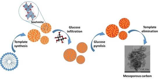
Mesoporous Carbon Production by Nanocasting Technique Using Boehmite as a Template


Abstract
:
1. Introduction
2. Results and Discussion
3. Materials and Methods
3.1. Mesoporous Boehmite Synthesis
3.2. Mesoporous Carbons Synthesis
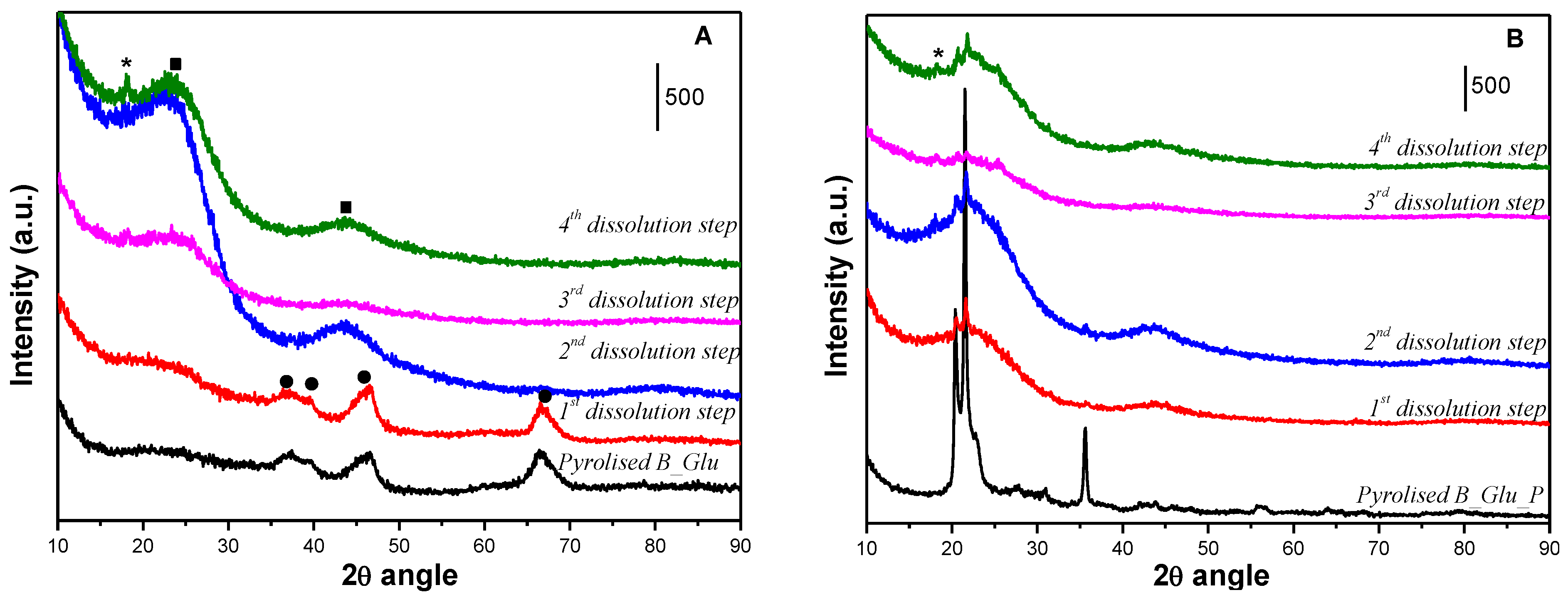
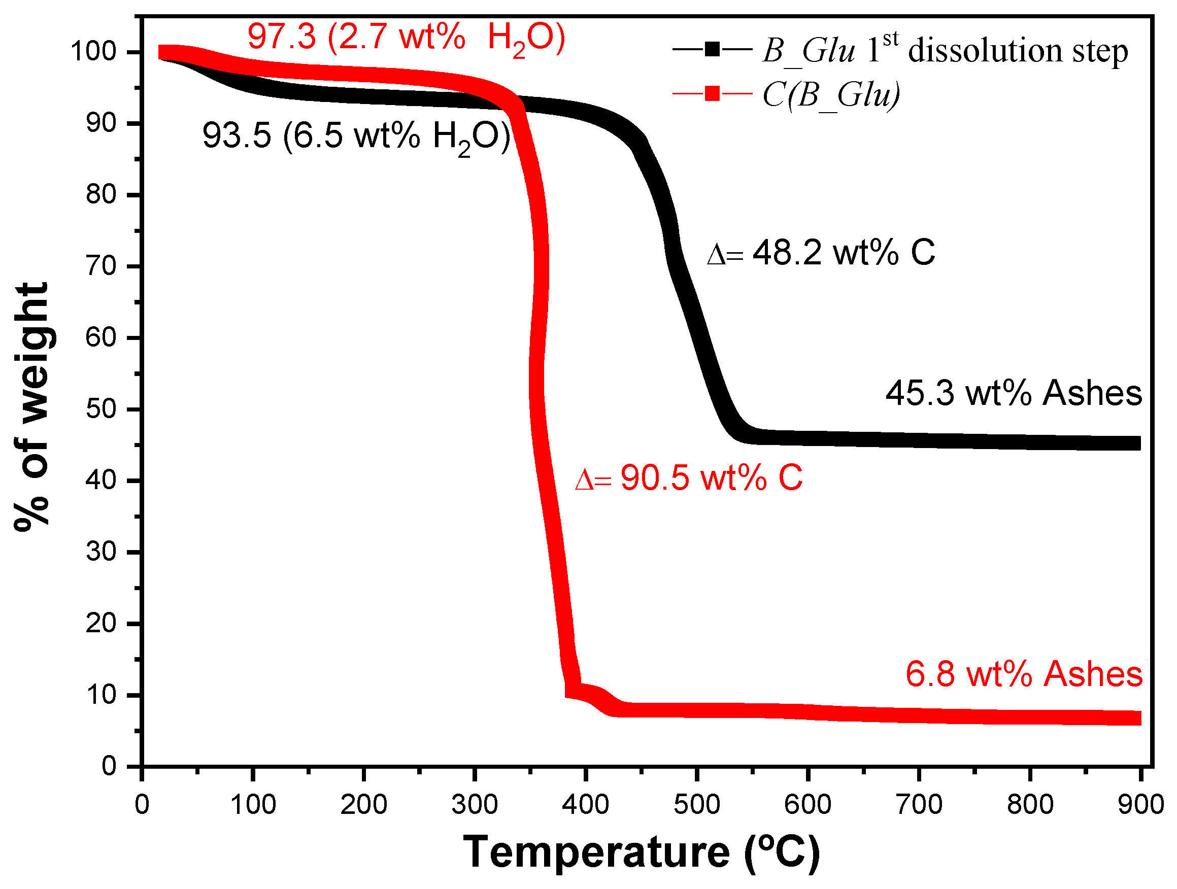
3.3. Template Removal
3.4. Characterization Techniques
4. Conclusions
Supplementary Materials
Author Contributions
Funding
Data Availability Statement
Conflicts of Interest
References
- Milazzo, G. IUPA C-Manual of Symbols and Terminology for Physico-chemical Quantities and Units. J. Electroanal. Chem. Interfacial Electrochem. 2006, 128, 285–286. [Google Scholar] [CrossRef]
- Lu, A.H.; Schüth, F. Nanocasting: A Versatile Strategy for Creating Nanostructured Porous Materials; Royal Society of Chemistry: London, UK, 2006. [Google Scholar]
- Inagaki, M.; Toyoda, M.; Soneda, Y.; Tsujimura, S.; Morishita, T. Templated mesoporous carbons: Synthesis and applications. Carbon 2016, 107, 448–473. [Google Scholar] [CrossRef]
- Dhawane, S.H.; Kumar, Y.; Halder, G. Recent advancement and prospective of heterogeneous carbonaceous catalysts in chemical and enzymatic transformation of biodiesel. Energy Convers. Manag. 2018, 167, 176–202. [Google Scholar] [CrossRef]
- Lee, J.; Kim, J.; Hyeon, T. Recent progress in the synthesis of porous carbon materials. Adv. Mater. 2006, 18–16, 2073–2094. [Google Scholar] [CrossRef]
- Liang, C.; Li, Z.; Dai, S. Mesoporous carbon materials: Synthesis and modification. Angew. Chemie-Int. Ed. 2008, 47, 3696–3717. [Google Scholar] [CrossRef] [PubMed]
- Bauer, J.; Schroer, A.; Schwaiger, R.; Kraft, O. Approaching theoretical strength in glassy carbon nanolattices. Nat. Mater. 2016, 15, 438–443. [Google Scholar] [CrossRef]
- Zhang, X.; Zhong, L.; Mateos, A.; Kudo, A.; Vyatskikh, A.; Gao, H.; Greer, J.R.; Li, X. Theoretical strength and rubber-like behaviour in micro-sized pyrolytic carbon. Nat. Nanotechnol. 2019, 14, 762–769. [Google Scholar] [CrossRef] [PubMed] [Green Version]
- Crook, C.; Bauer, J.; Guell, A.; Santos de Oliveira, C.; Martins de Sousa, J.; Berger, J.B.; Valdevit, L. Plate-nanolattices at the theoretical limit of stiffness and strength. Nat. Commun. 2020, 11, 1579. [Google Scholar] [CrossRef] [Green Version]
- Enterría, M.; Figueiredo, J.L. Nanostructured mesoporous carbons: Tuning texture and surface chemistry. Carbon 2016, 108, 79–102. [Google Scholar] [CrossRef]
- Zhong, R.; Sels, B.F. Sulfonated mesoporous carbon and silica-carbon nanocomposites for biomass conversion. Appl. Catal. B Environ. 2018, 236, 518–545. [Google Scholar] [CrossRef]
- Alegre, C.; Sebastián, D.; Gálvez, M.E.; Moliner, R.; Lázaro, M.J. Sulfurized carbon xerogels as Pt support with enhanced activity for fuel cell applications. Appl. Catal. B Environ. 2016, 192, 260–267. [Google Scholar] [CrossRef]
- Alegre, C.; Sebastián, D.; Gálvez, M.E.; Baquedano, E.; Moliner, R.; Aricò, A.S.; Baglio, V.; Lázaro, M.J. N-doped carbon xerogels as Pt support for the electro-reduction of oxygen. Materials 2017, 10, 1092. [Google Scholar] [CrossRef]
- Song, Y.; Liu, G.; Yuan, Z.Y. N-, P- and B-doped mesoporous carbons for direct dehydrogenation of propane. RSC Adv. 2016, 6, 94636–94642. [Google Scholar] [CrossRef]
- Chen, C.; Zhang, J.; Zhang, B.; Yu, C.; Peng, F.; Su, D. Revealing the enhanced catalytic activity of nitrogen-doped carbon nanotubes for oxidative dehydrogenation of propane. Chem. Commun. 2013, 49, 8151–8153. [Google Scholar] [CrossRef]
- Mao, S.; Li, B.; Su, D. The first principles studies on the reaction pathway of the oxidative dehydrogenation of ethane on the undoped and doped carbon catalyst. J. Mater. Chem. A. 2014, 2, 5287–5294. [Google Scholar] [CrossRef]
- Gotoh, Y.; Tamada, K.; Akuzawa, N.; Fujishige, M.; Takeuchi, K.; Endo, M.; Matsumoto, R.; Soneda, Y.; Takeichi, T. Preparation of air-stable and highly conductive potassium-intercalated graphite sheet. J. Phys. Chem. Solids 2013, 74, 1482–1486. [Google Scholar] [CrossRef]
- Liu, K.; Zhang, J.; Ding, R.; Zheng, X.; Yang, T.; Wang, C.; Chen, M. Potassium-assisted carbonization of pyrrole to prepare nanorod-structured graphitic carbon with a high surface area for high-rate supercapacitors. Carbon 2019, 155, 326–333. [Google Scholar] [CrossRef]
- Wei, Z.; Wang, J.; Sun, J.; Zhang, Z.; Lu, B.; Guo, J. Thermal puffing promoting the synthesis of N-doped hierarchical porous carbon−CoOx composites for alkaline water reduction. ACS Omega 2021, 6, 6474–6481. [Google Scholar] [CrossRef]
- Yan, X.-L.; Li, H.-F.; Wang, C.; Jiang, B.-B.; Hu, H.-Y.; Xie, N.; Wu, M.H.; Vinodgopal, K.; Dai, G.P. Melamine as a single source for fabrication of mesoscopic 3D composites of N-doped carbon nanotubes on graphene. RSC Adv. 2018, 8, 12157. [Google Scholar] [CrossRef] [Green Version]
- Li, D.; Chen, W.; Wu, J.; Jia, C.Q.; Jiang, X. The preparation of waste biomass-derived N- doped carbons and their application in acid gas removal: Focus on N functional groups. J. Mater. Chem. A 2020, 8, 24977. [Google Scholar] [CrossRef]
- Zhang, X.; Cui, W.; Page, K.L.; Pearce, C.I.; Bowden, M.E.; Graham, T.R.; Shen, Z.; Li, P.; Wang, Z.; Kerisit, S.; et al. Size and morphology controlled synthesis of boehmite nanoplates and crystal growth mechanisms. Cryst. Growth Des. 2018, 18, 3596–3606. [Google Scholar] [CrossRef]
- Takagaki, A.; Jung, J.C.; Hayashi, S. Solid Lewis acidity of boehmite γ-AlO(OH) and its catalytic activity for transformation of sugars in water. RSC Adv. 2014, 4, 43785–43791. [Google Scholar] [CrossRef] [Green Version]
- Bokhimi, X.; Toledo-Antonio, J.A.; Guzman-Castillo, M.L.; Hernandez-Beltran, F. Relationship between crystallite size and bond lengths in boehmite. J. Solid State Chem. 2001, 159, 32–40. [Google Scholar] [CrossRef]
- Shirai, T.; Watanabe, H.; Fuji, M.; Takahashi, M. Structural properties and surface characteristics on aluminum oxide powders. Annu. Rep. Ceram. Res. Lab. Nagoya Inst. Technol. 2009, 9, 23–31. [Google Scholar]
- Samain, L.; Jaworski, A.; Edén, M.; Ladd, D.M.; Seo, D.K.; García-García, F.J.; Häussermann, U. Structural analysis of highly porous γ-Al2O3. J. Solid State Chem. 2014, 217, 1–8. [Google Scholar] [CrossRef]
- Gu, J.; Wang, J.; Leszczynski, J. Structure and energetics of (111) surface of γ-Al2O3: Insights from DFT including periodic boundary approach. ACS Omega 2018, 3, 1881–1888. [Google Scholar] [CrossRef] [Green Version]
- Liang, Y.; Feng, X.; Zhi, L.; Kolb, U.; Müllen, K. A simple approach towards one-dimensional mesoporous carbon with superior electrochemical capacitive activity. Chem. Commun. 2009, 7, 809–811. [Google Scholar] [CrossRef] [Green Version]
- Zhao, G.; He, J.; Zhang, C.; Zhou, J.; Chen, X.; Wang, T. Highly dispersed Pt nanoparticles on mesoporous carbon nanofibers prepared by two templates. J. Phys. Chem. C 2008, 112, 1028–1033. [Google Scholar] [CrossRef]
- Mezni, A.; Altalhi, T.; Ben Saber, N.; Aldalbahi, A.; Boulehmi, S.; Santos, A.; Losic, D. Size- and shape-controlled synthesis of well-organised carbon nanotubes using nanoporous anodic alumina with different pore diameters. J. Colloid Interface Sci. 2017, 491, 375–389. [Google Scholar] [CrossRef]
- Gallo, J.M.R.; Trapp, M.A. The chemical conversion of biomass-derived saccharides: An overview. J. Braz. Chem. Soc. 2017, 28, 1586–1607. [Google Scholar] [CrossRef]
- Sharma, V.T.; Halanur, M.; Kamath, S.V.; Mondal, D.; Kotrappanavar, N.S. Fe-Al based nanocomposite reinforced hydrothermal carbon: Efficient and robust absorbent for anionic dyes. Chemosphere 2020, 259, 127421. [Google Scholar] [CrossRef] [PubMed]
- Sun, F.; Qu, Z.; Wang, H.; Liu, X.; Pei, T.; Han, R.; Gao, J.; Zhao, G.; Lu, Y. Vapor deposition of aluminium oxide into N-rich mesoporous carbon framework as a reversible sulfur host for lithium-sulfur battery cathode. Nano Research 2021, 14, 131–138. [Google Scholar] [CrossRef]
- Yin, Y.; Zhang, J.; Sheng, C. Effect of pyrolysis temperature on the char micro-structure and reactivity of NO reduction. Korean J. Chem. Eng. 2009, 26, 895. [Google Scholar] [CrossRef]
- Collins, J.; Zheng, D.; Ngo, T.; Qu, D.; Foster, M. Partial graphitization of activated carbon by surface acidification. Carbon 2014, 79, 500–517. [Google Scholar] [CrossRef]
- Xin, S.; Yang, H.; Chen, Y.; Yanga, M.; Chena, L.; Wanga, X.; Chena, H. Chemical structure evolution of char during the pyrolysis of cellulose. J. Anal. Appl Pyrolysis 2015, 116, 263–271. [Google Scholar] [CrossRef]
- Li, Z.Q.; Lu, C.J.; Xia, Z.P.; Zhou, Y.; Luo, Z. X-ray diffraction patterns of graphite and turbostratic carbon. Carbon 2007, 45, 1686–1695. [Google Scholar] [CrossRef]
- Rodríguez, N.; Agamez-Pertuz, Y.Y.; Romero, E.; Díaz-Velásquez, J.J.; Odriozola, J.A.; Centeno, M.A. Effect of starch as binder in carbon aerogel and carbon xerogel preparation. J. Non-Cryst. Solids 2019, 522, 119554. [Google Scholar] [CrossRef]
- Thommes, M.; Kaneko, K.; Neimark, A.V.; Olivier, J.P.; Rodríguez-Reinoso, F.; Rouquerol, J.; Sing, K.S.V. Physisorption of gases, with special reference to the evaluation of surface area and pore size distribution (IUPAC technical report). Pure Applied Chem. 2015, 87, 1051–1069. [Google Scholar] [CrossRef] [Green Version]
- Leofanti, G.; Padovan, M.; Tozzola, G.; Venturelli, B. Surface area and pore texture of catalysts. Catal. Today 1998, 41, 207–219. [Google Scholar] [CrossRef]
- Liu, B.; Liu, L.; Yu, Y.; Zhang, Y.; Chen, A. Synthesis of mesoporous carbon with tunable pore size for supercapacitors. New J. Chem. 2020, 44, 1036. [Google Scholar] [CrossRef]
- Liu, B.; Yang, M.; Chen, H.B.; Liu, Y.J.; Yang, D.G.; Li, H.M. Graphene-like porous carbon nanosheets derived from salvia splendens for high-rate performance supercapacitors. J. Power Sources 2018, 397, 1–10. [Google Scholar] [CrossRef]
- Ansari, H.; Joss, L.; Hwang, J.; Martin Trusler, J.P.; Maitland, G.; Pini, R. Supercritical adsorption in micro- and meso-porous carbons and its utilization for textural characterization. Micropor. Mesopor. Mat. 2020, 308, 110537. [Google Scholar] [CrossRef]
- Saygılı, H.; Güzel, F. High surface area mesoporous activated carbon from tomato processing solid waste by zinc chloride activation: Process optimization, characterization and dyes adsorption. J. Clean. Prod. 2016, 113, 995–1004. [Google Scholar] [CrossRef]
- Santos, J.L.; Megias-Sayago, C.; Ivanova, S.; Centeno, M.A.; Odriozola, J.A. Functionalized biochars as supports for Pd/C catalysts for efficient hydrogen production from formic acid. Appl. Catal. B Environ. 2021, 282, 119615. [Google Scholar] [CrossRef]
- Liu, H.; Zhang, Y.; Li, R.; Sun, X.; Abou-Rachid, H. Thermal and chemical durability of nitrogen-doped carbon nanotubes. J. Nanopart Res. 2012, 14, 1016. [Google Scholar] [CrossRef]
- Liu, H.; Zhang, Y.; Li, R.; Sun, X.; Désilets, S.; Abou-Rachid, H.; Jaidann, M.; Lussier, L.S. Structural and morphological control. nitrogen incorporation and stability of aligned nitrogen-doped carbon nanotubes. Carbon 2010, 48, 1498–1507. [Google Scholar] [CrossRef]
- Ferrari, A.C.; Robertson, J. Interpretation of Raman spectra of disordered and amorphous carbon. Phys. Rev. B Condens. Matter. 2000, 61, 14095–14107. [Google Scholar] [CrossRef] [Green Version]
- Kouketsu, Y.; Mizukami, T.; Mori, H.; Endo, S.; Aoya, M.; Hara, H.; Nakamura, D.; Wallis, S. A new approach to develop the Raman carbonaceous material geothermometer for low-grade metamorphism using peak width. Island Arc. 2014, 23, 33–50. [Google Scholar] [CrossRef]
- Centeno, M.A.; Grange, P. Platinum aluminophosphate oxynitride (Pt-AlPON) catalysts. Consequences of surface hydrolysis and heating processes on the structure. J. Phys. Chem. B 1999, 103, 2431–2438. [Google Scholar] [CrossRef]
- Tripathi, M.; Sahu, J.N.; Ganesan, P. Effect of process parameters on production of biochar from biomass waste through pyrolysis: A review. Renew. Sust. Energ. Rev. 2016, 55, 467–481. [Google Scholar] [CrossRef]
- Jafri, N.; Wong, W.Y.; Doshi, V.; Yoon, L.W.; Cheah, K.H. A review on production and characterization of biochars for application in direct carbon fuel cells. Process. Saf. Environ. Prot. 2018, 118, 152–166. [Google Scholar] [CrossRef]
- Santos, J.L.; Centeno, M.A.; Odriozola, J.A. Reductant atmospheres during slow pyrolysis of cellulose: First approach to obtaining efficient char-based catalysts in one po. J. Anal. Appl. Pyrolysis 2020, 148, 104821. [Google Scholar] [CrossRef]
- González, R.D.; López, T.; Gómez, R. Sol-Gel preparation of supported metal catalysts. Catal. Today 1997, 35, 293–317. [Google Scholar] [CrossRef]
- Centeno, M.A.; Portales, C.; Carrizosa, I.; Odriozola, J.A. Gold supported CeO2/Al2O3 catalysts for CO oxidation: Influence of the ceria phase. Catal. Lett. 2005, 102, 289–297. [Google Scholar] [CrossRef]
- Du, S.; Valla, J.A.; Bollas, G.M. Characteristics and origin of char and coke from fast and slow, catalytic and thermal pyrolysis of biomass and relevant model compounds. Green Chem. 2013, 15, 3214–3229. [Google Scholar] [CrossRef]
- Alexander, L.E.; Sommer, E.C. Systematic analysis of carbon black structures. J. Phys. Chem. 1956, 60, 1646–1649. [Google Scholar] [CrossRef]
- Okolo, G.N.; Neomagus, W.J.P.; Everson, C.; Roberts, J.; Bunt, R.; Sakurovs, R.; Mathews, P. Chemical–structural properties of South African bituminous coals: Insights from wide angle XRD–carbon fraction analysis, ATR–FTIR, solid state 13C NMR, and HRTEM techniques. Fuel 2015, 158, 779–792. [Google Scholar] [CrossRef]


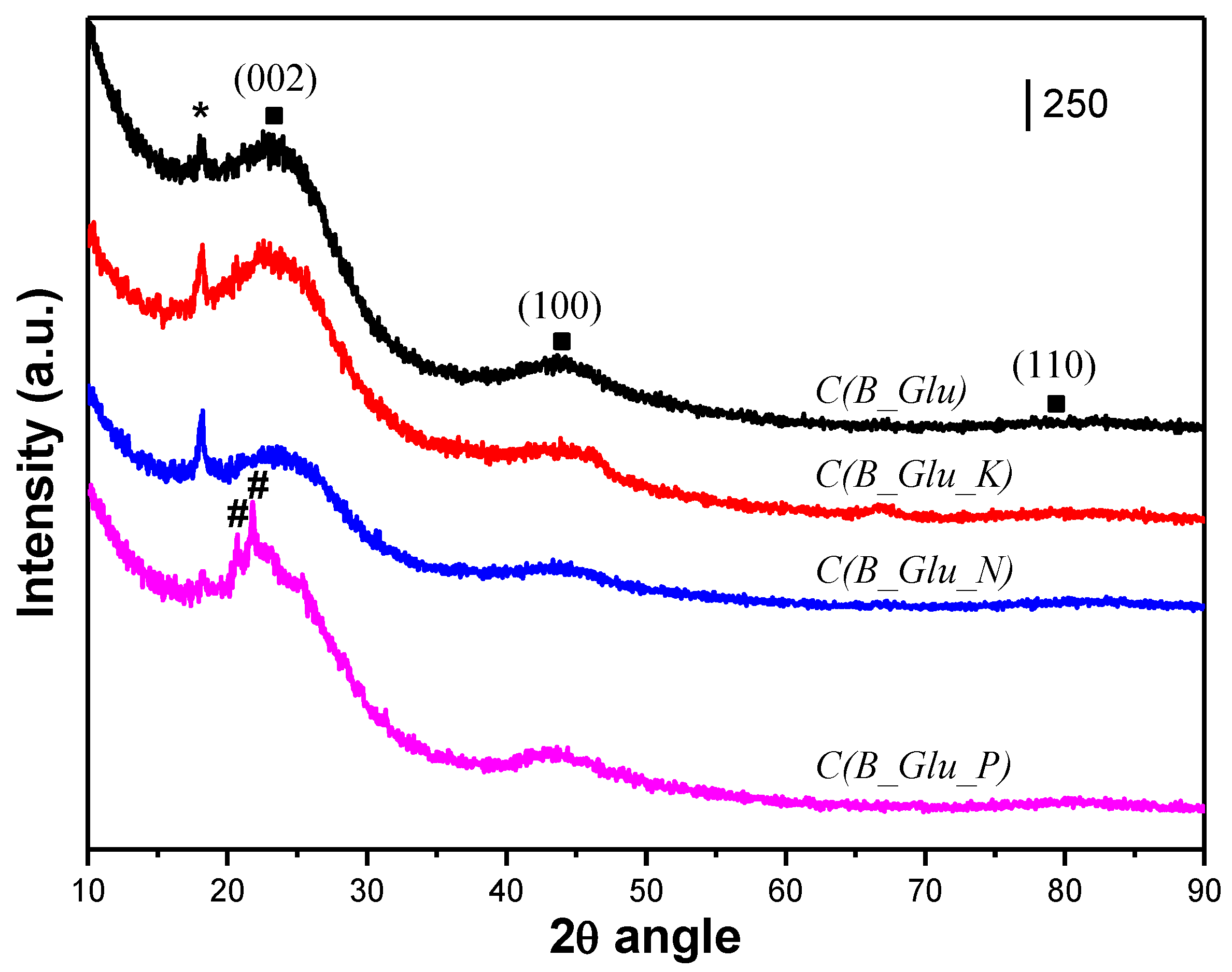
| Sample | Lc (Å) | La (Å) | R | d002 | Nave |
|---|---|---|---|---|---|
| C(B_Glu) | 14 | 29 | 1.56 | 3.63144 | 5 |
| C(B_Glu_K) | 10 | 29 | 1.7 | 3.72021 | 4 |
| C(B_Glu_N) | 10 | 29 | 1.6 | 3.6451 | 4 |
| C(B_Glu_P) | 14 | 24 | 1.64 | 3.79856 | 5 |
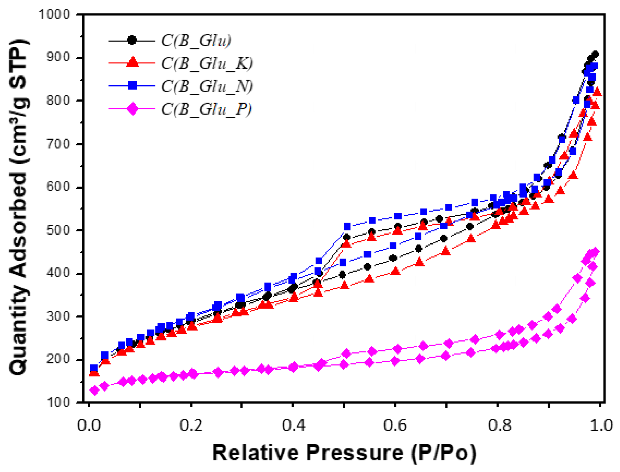
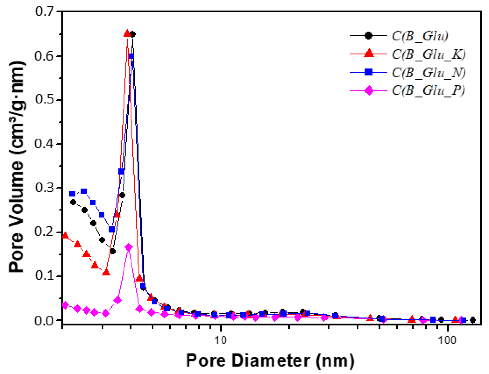
| Sample | BET m2/g | Micropore % | BJH desor Pore vol. cm3/g | 4V/A by BET Pore diam. nm |
|---|---|---|---|---|
| C(B_Glu) | 1038 | 5.9 | 1.50 | 4.8 |
| C(B_Glu_K) | 990 | 11.2 | 1.26 | 4.5 |
| C(B_Glu_N) | 1078 | 2.5 | 1.47 | 4.5 |
| C(B_Glu_P) | 569 | 57.3 | 0.54 | 3.7 |
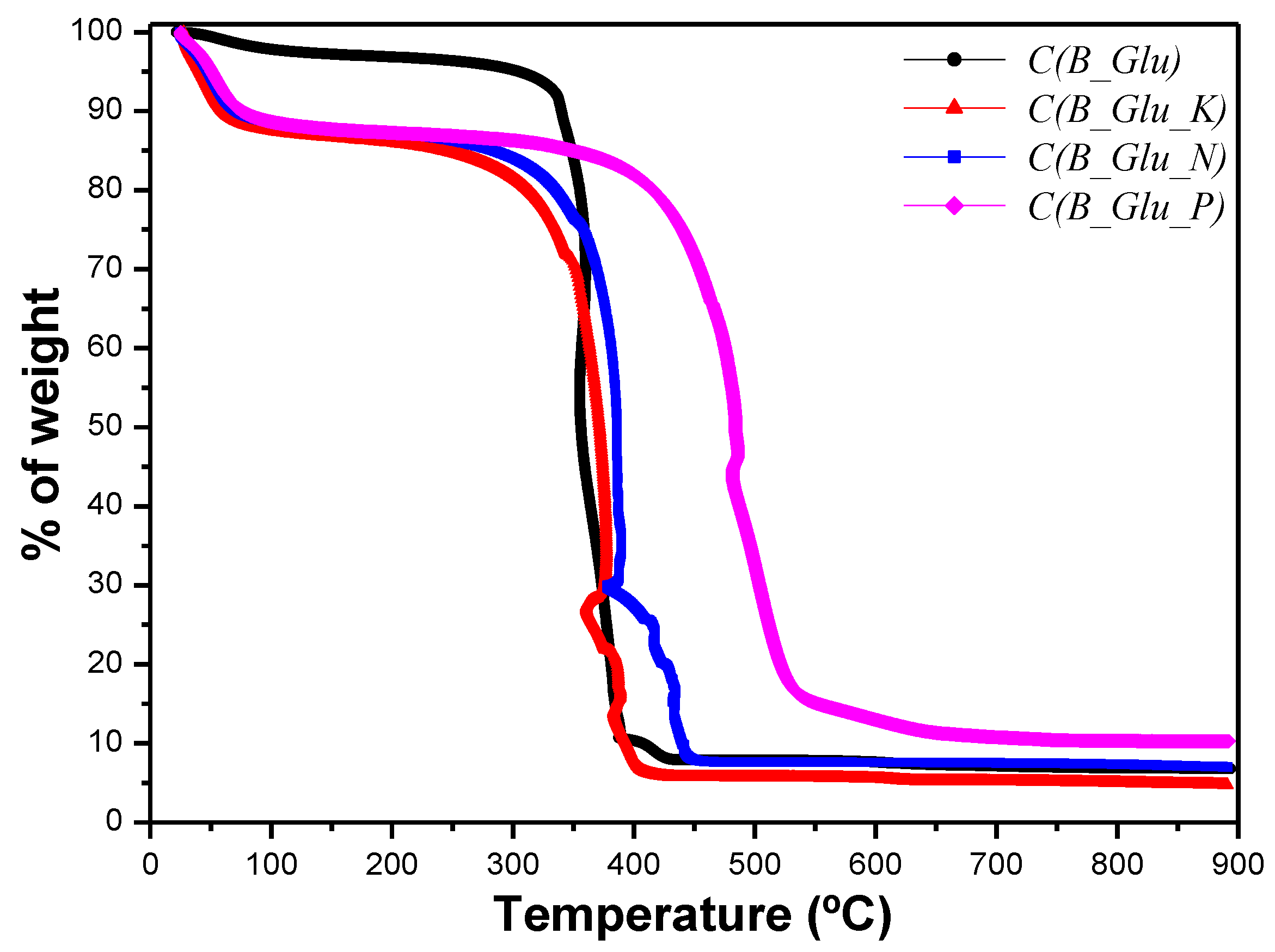
| Sample | Water loss T (°C) | Water loss wt % | Combustion T (°C) | Ashes wt % |
|---|---|---|---|---|
| B_Glu(1) | 63 | 6.5 | 451 | 45.3 |
| C(B_Glu) | 61 | 257 | 342 | 6.8 |
| B_Glu_K(1) | 66 | 6.2 | 457 | 52.2 |
| C(B_Glu_K) | 43 | 13.4 | 357 | 4.8 |
| B_Glu_N(1) | 65 | 6.5 | 462 | 41.0 |
| C(B_Glu_N) | 54 | 12.0 | 363 | 7.3 |
| B_Glu_P(1) | 55 | 8.1 | 484 | 13.0 |
| C(B_Glu_P) | 51 | 12.7 | 482 | 10.2 |
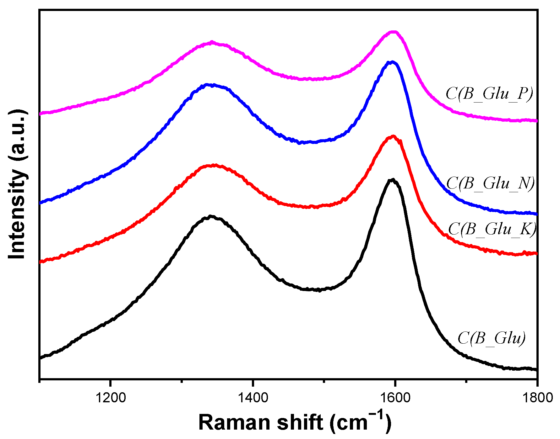
| Sample | D/G ratio |
|---|---|
| C(B_Glu) | 0.84 |
| C(B_Glu_K) | 0.85 |
| C(B_Glu_N) | 0.89 |
| C(B_Glu_P) | 0.82 |
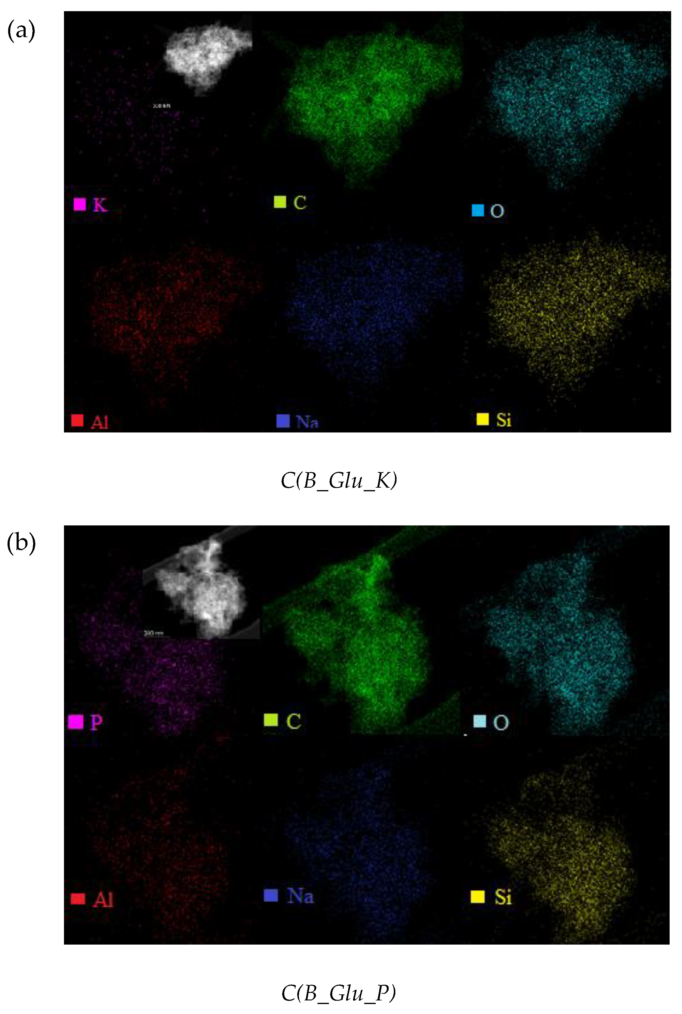
| Mass Fraction (%) | C(B_Glu) | C(B_Glu_K) | C(B_Glu_N) | C(B_Glu_P) I region | C(B_Glu_P) II region |
|---|---|---|---|---|---|
| C | 83.39 | 65.42 | 74.75 | 75.26 | 87.02 |
| O | 9.76 | 19.05 | 15.40 | 12.92 | 8.72 |
| Na | 1.83 | 3.94 | 2.13 | 1.82 | 1.25 |
| Al | 0.16 | 4.38 | 1.18 | 0.22 | 0.16 |
| Si | 4.86 | 7.17 | 6.48 | 7.61 | 1.86 |
| K | - | 0.04 | - | - | - |
| N | - | - | 0.07 | - | - |
| P | - | - | - | 2.81 | 0.98 |
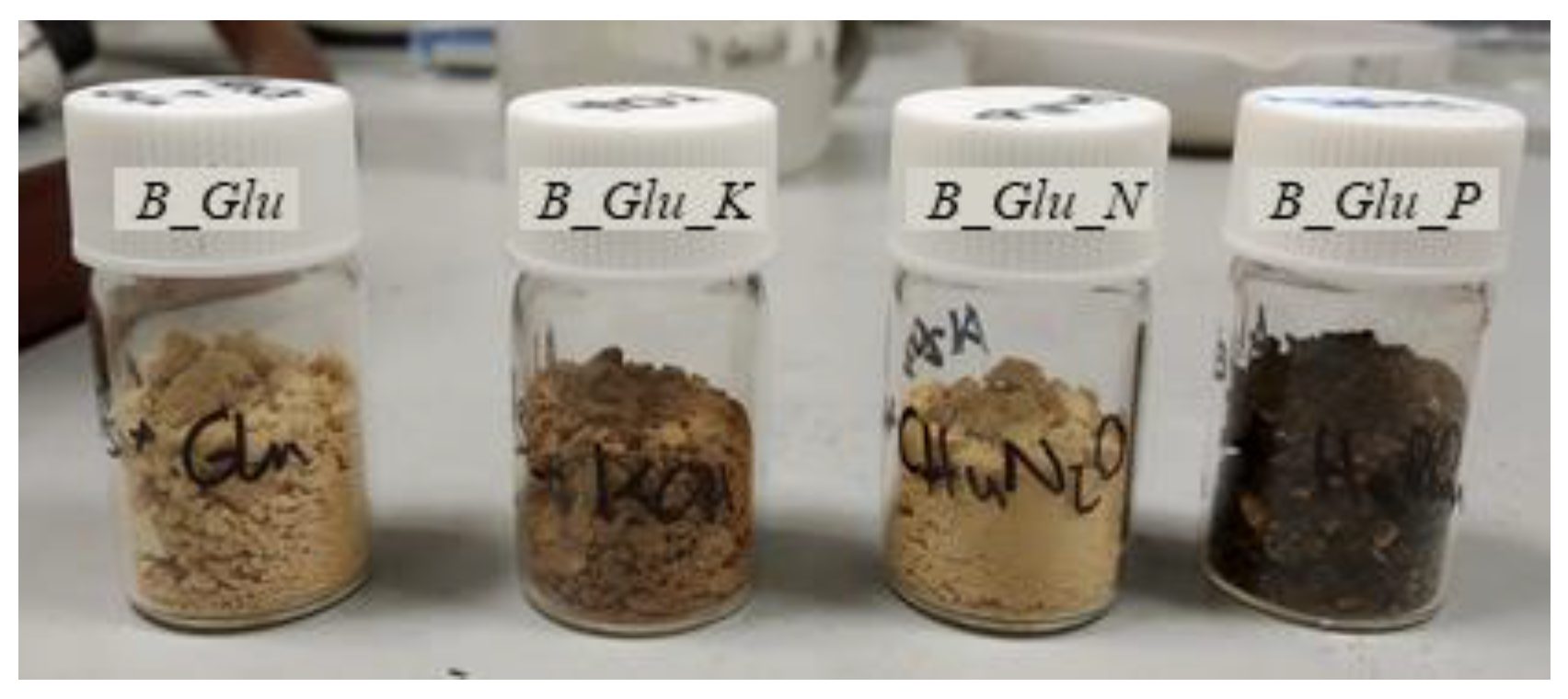
| Additive | As prepared samples | Obtained carbons |
|---|---|---|
| -- | B_Glu | C(B_Glu) |
| KOH | B_Glu_K | C(B_Glu_K) |
| Urea | B_Glu_N | C(B_Glu_N) |
| H3PO4 | B_Glu_P | C(B_Glu_P) |
Publisher’s Note: MDPI stays neutral with regard to jurisdictional claims in published maps and institutional affiliations. |
© 2021 by the authors. Licensee MDPI, Basel, Switzerland. This article is an open access article distributed under the terms and conditions of the Creative Commons Attribution (CC BY) license (https://creativecommons.org/licenses/by/4.0/).
Share and Cite
Ortega-Franqueza, M.; Ivanova, S.; Domínguez, M.I.; Centeno, M.Á. Mesoporous Carbon Production by Nanocasting Technique Using Boehmite as a Template. Catalysts 2021, 11, 1132. https://doi.org/10.3390/catal11091132
Ortega-Franqueza M, Ivanova S, Domínguez MI, Centeno MÁ. Mesoporous Carbon Production by Nanocasting Technique Using Boehmite as a Template. Catalysts. 2021; 11(9):1132. https://doi.org/10.3390/catal11091132
Chicago/Turabian StyleOrtega-Franqueza, María, Svetlana Ivanova, María Isabel Domínguez, and Miguel Ángel Centeno. 2021. "Mesoporous Carbon Production by Nanocasting Technique Using Boehmite as a Template" Catalysts 11, no. 9: 1132. https://doi.org/10.3390/catal11091132
APA StyleOrtega-Franqueza, M., Ivanova, S., Domínguez, M. I., & Centeno, M. Á. (2021). Mesoporous Carbon Production by Nanocasting Technique Using Boehmite as a Template. Catalysts, 11(9), 1132. https://doi.org/10.3390/catal11091132