Oxide and Organic–Inorganic Halide Perovskites with Plasmonics for Optoelectronic and Energy Applications: A Contributive Review


Abstract
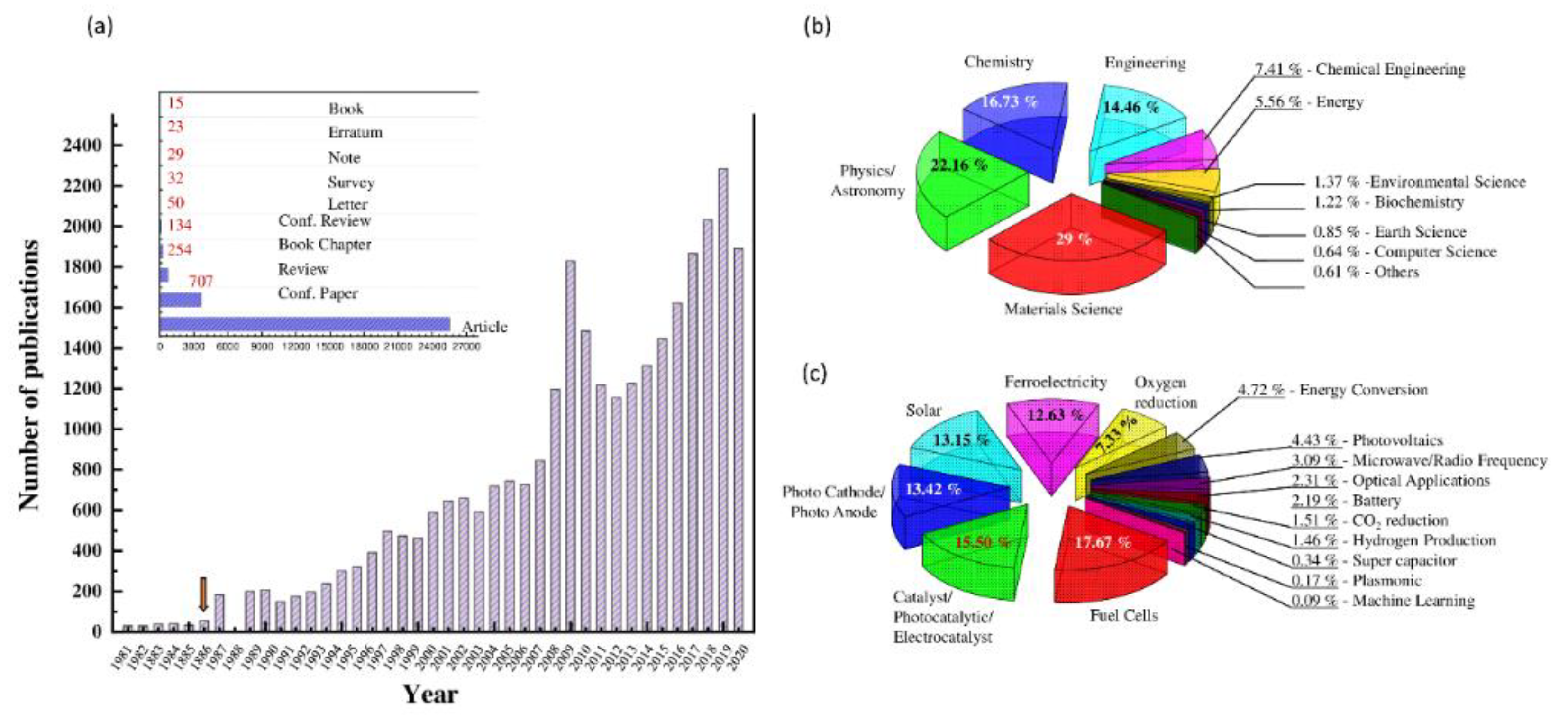
:1. Introduction
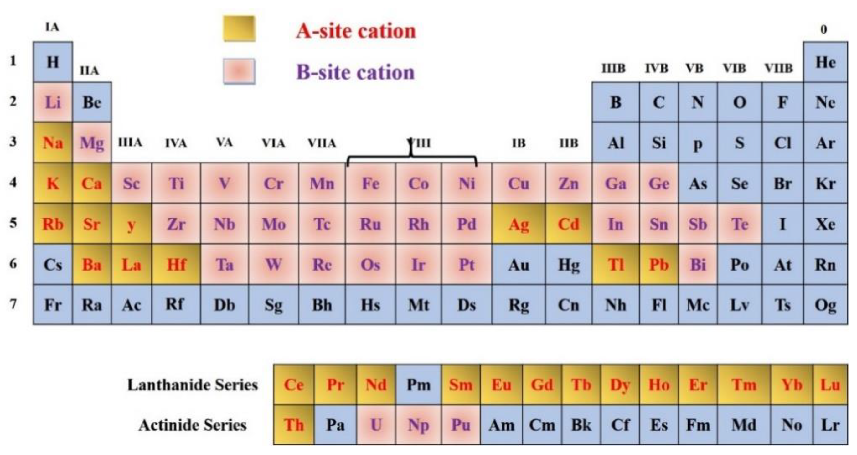
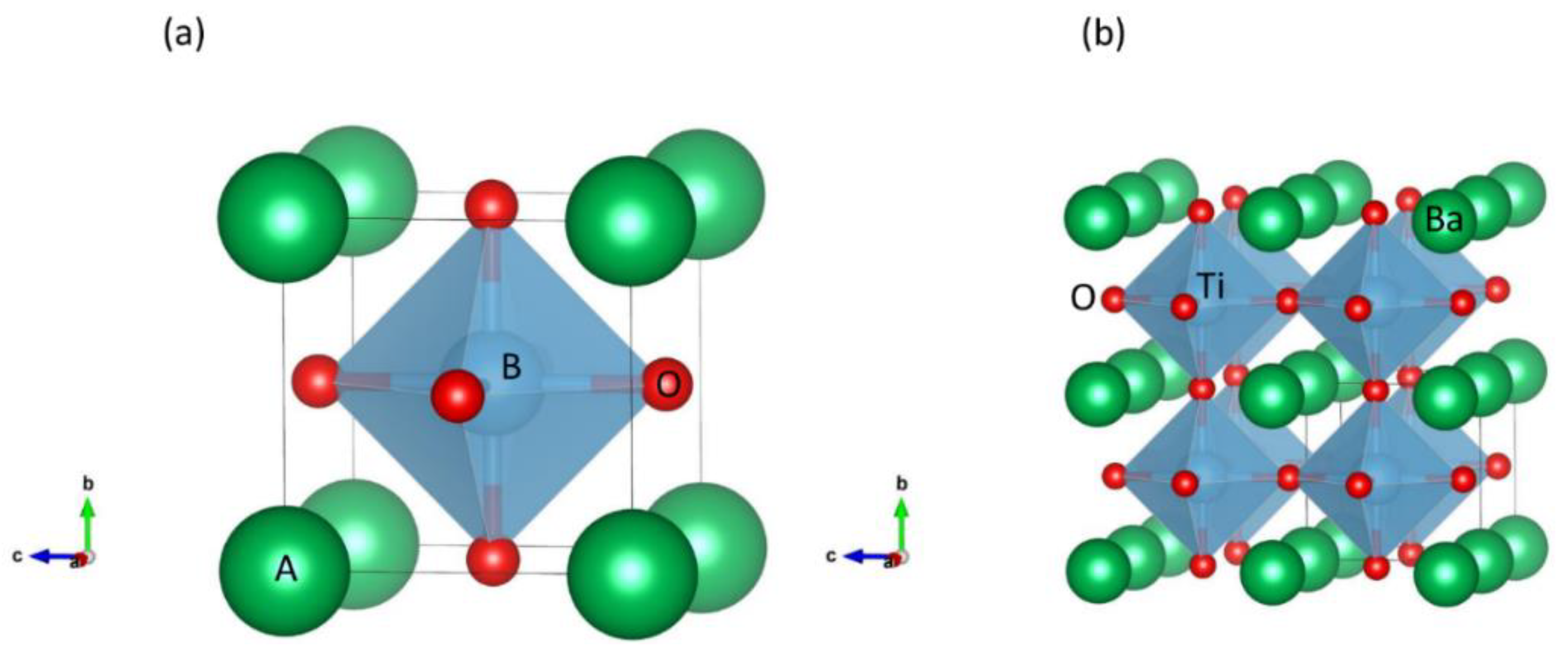
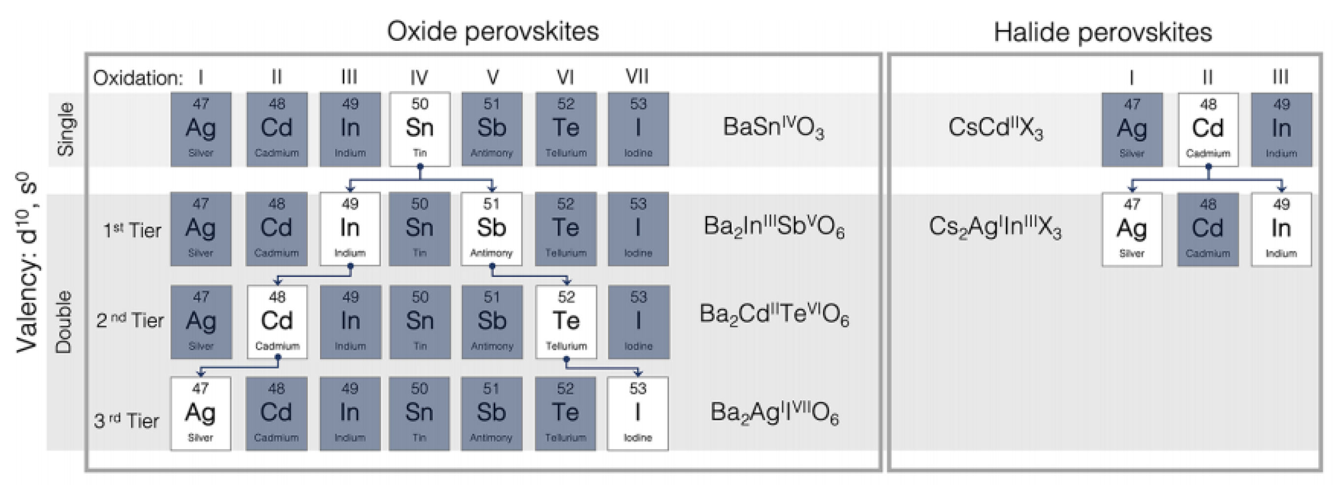
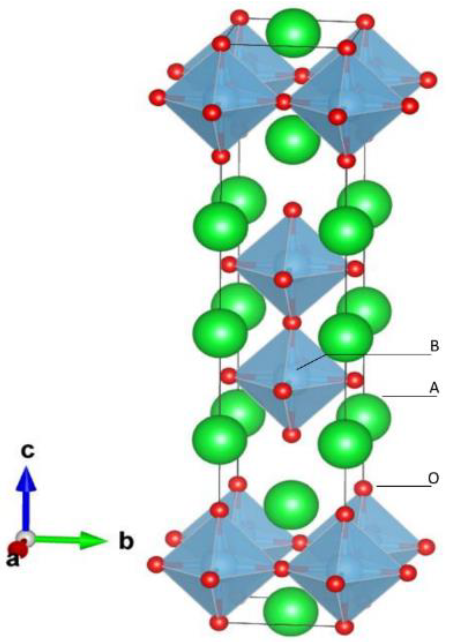
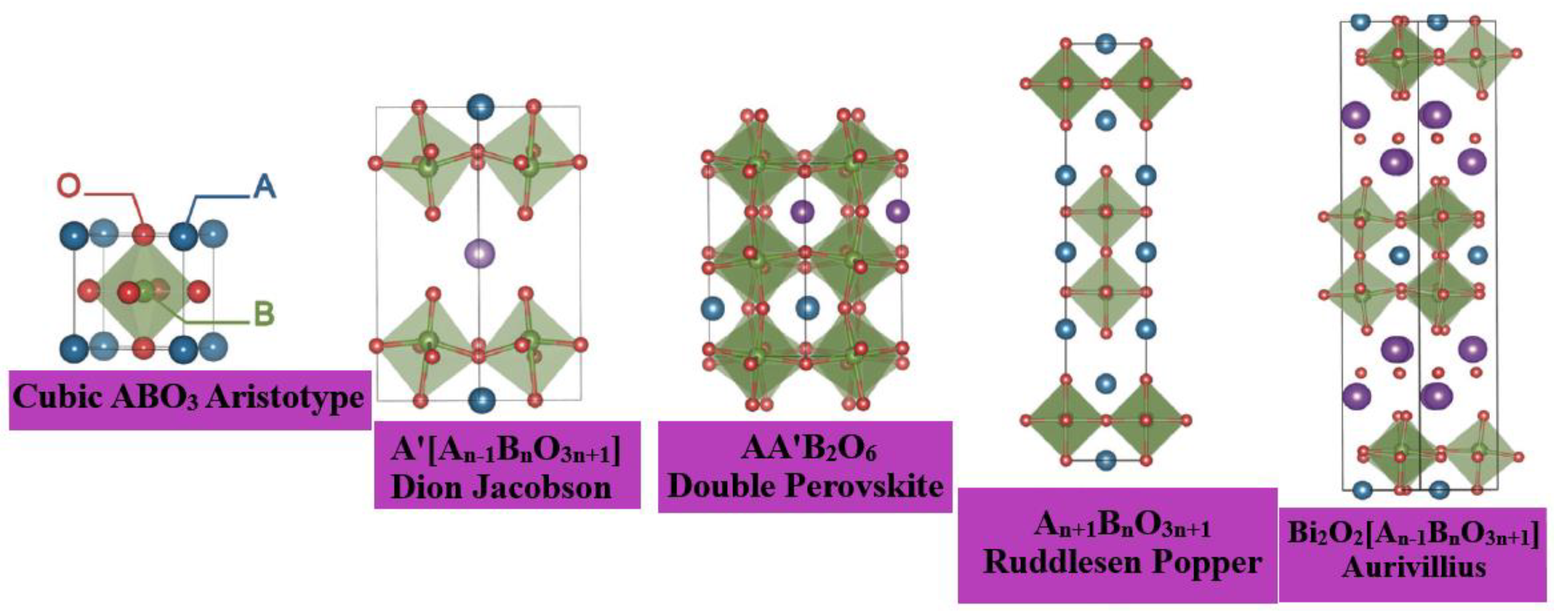
2. Structure of Oxide Perovskite
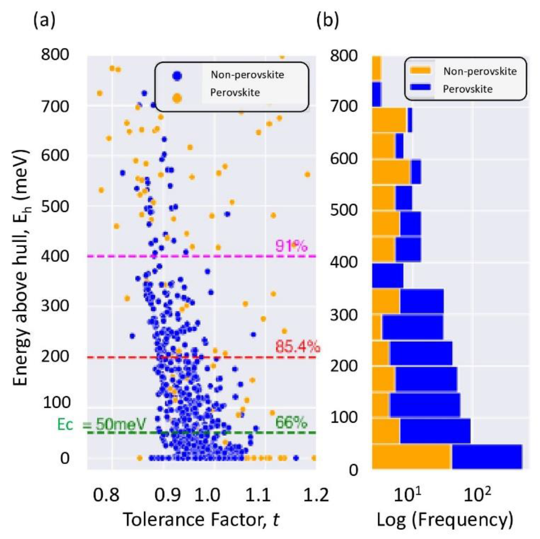
3. Formability versus Thermodynamic Stability
4. Typical Properties of Perovskite Oxides
4.1. Dielectric Properties
4.2. Electrical Conductivity and Superconductivity
4.3. Catalytic Activity
4.4. Photocatalytic Activity
5. Multiferroic Oxide Thin Films
5.1. Synthesis of Multiferroic Thin Films and Strain Engineering
5.2. Bi-Containing Multiferroic Thin Films
- (i).
- BiFeO3
- (ii).
- BiMnO3 (BMO)
- (iii).
- BiCrO3 (BCO)
- (iv).
- Bi-Based Ordered Double Perovskites
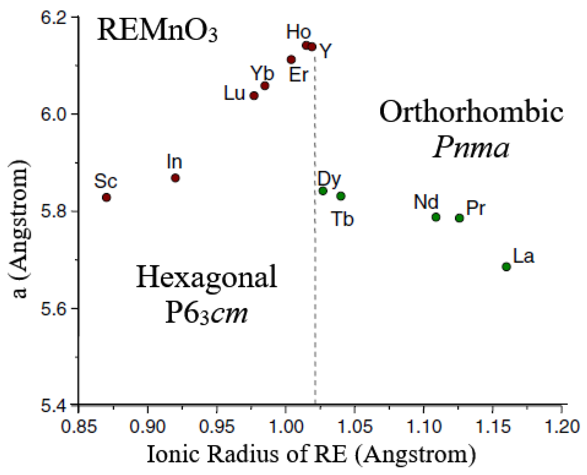
5.3. Multiferroic Rare-Earth Manganites
- (i).
- Antiferromagnetic REMnO3
- (ii).
- Orthorhombic REMnO3 with Spiral Spin Order (SSO)
5.4. Other Multiferroic Thin Films
5.5. Magnetism in Multiferroic Thin Films
6. Photovoltaic Effect in Multiferroic Thin Films as a Photoactive Layer
7. Oxygen-Separating Membrane
8. Perovskite Oxides for Solid Oxide Fuel Cells (SOFCs)
- (i).
- Cathode
- (ii).
- Anode
- (iii).
- Electrolyte
9. Plasmonic Perovskite Solar Cells
9.1. Plasmonics in Electron Transport Material
9.2. Plasmonics in Absorber Material
9.3. Plasmonics in the Hole Transport Material
9.4. Plasmonics in Semi-Transparent PSCs
10. Summary and Outlook
Author Contributions
Funding
Conflicts of Interest
Abbreviations
| AFM | Atomic force microscopy |
| BCO | BiCrO3 |
| BFO | BiFeO3 |
| BMO | BiMnO3 |
| BSCF | Ba0:5Sr0:5Fe0:8Co0:2O3 |
| BTO | BaTiO3 |
| CIGS | CuInGaS |
| DMI | Dzyaloshinskii–Moriya interaction |
| ECPs | Electrode-coupled plasmons |
| ETL | Electron transport Layer |
| FM | Ferromagnetic |
| HTL | Hole transport layer |
| Isc | Short-circuit current |
| LAO | LaAlO3 |
| LGSM | LaGaO3 doped with Sr and Mg |
| MBE | Molecular beam epitaxy |
| MOCVD | Metal organic chemical vapor deposition |
| NRs | Nanorods |
| PCE | Power conversion efficiency |
| PFM | Piezoelectric force microscopy |
| PHJ | Planar heterojunction |
| PLD | Pulsed laser deposition |
| PSCs | Perovskite solar cells |
| PV | Photovoltaics |
| RE | Rare-earth |
| RHEED | Reflection high-energy electron diffraction |
| SG Transition | Spin glass transition |
| SOFCs | Solid oxide fuel cells |
| SOTA | State-of-the-art |
| SSO | Spiral spin order |
| STC | Standard test conditions |
| Tc | Curie temperature |
| TFE | Ferroelectric temperature |
| TFM | Ferromagnetic temperature |
| TMO | Transition metal oxide |
| TWC | Three-way catalyst |
| Voc | Open-circuit voltage |
| YMO | YMnO3 |
| YSZ | Y0:16Zr0:84O2 |
References
- Wu, Y.; Li, J.; Xu, J.; Du, Y.; Huang, L.; Ni, J.; Cai, H.; Zhang, J. Organic-inorganic hybrid CH3NH3PbI3 perovskite materials as channels in thin-film field-effect transistors. RSC Adv. 2016, 6, 16243–16249. [Google Scholar] [CrossRef]
- Stranks, S.D.; Snaith, H. Metal-halide perovskites for photovoltaic and light-emitting devices. Nat. Nanotechnol. 2015, 10, 391–402. [Google Scholar] [CrossRef]
- Waser, R.; Dittmann, R.; Staikov, G.; Szot, K. Redox-Based Resistive Switching Memories-Nanoionic Mechanisms, Prospects, and Challenges. Adv. Mater. 2009, 21, 2632–2663. [Google Scholar] [CrossRef]
- Suntivich, J.; May, K.J.; Gasteiger, H.A.; Goodenough, J.B.; Shao-Horn, Y. A Perovskite Oxide Optimized for Oxygen Evolution Catalysis from Molecular Orbital Principles. Science 2011, 334, 1383–1385. [Google Scholar] [CrossRef]
- Reyren, N.; Thiel, S.; Caviglia, A.D.; Kourkoutis, L.F.; Hammerl, G.; Richter, C.; Schneider, C.W.; Kopp, T.; Ruetschi, A.-S.; Jaccard, D.; et al. Superconducting Interfaces Between Insulating Oxides. Science 2007, 317, 1196–1199. [Google Scholar] [CrossRef]
- Peña, M.A.; Fierro, J.L.G. Chemical Structures and Performance of Perovskite Oxides. Chem. Rev. 2001, 101, 1981–2018. [Google Scholar] [CrossRef]
- Kobayashi, K.-I.; Kimura, T.; Sawada, H.; Terakura, K.; Tokura, Y. Room-temperature magnetoresistance in an oxide material with an ordered double-perovskite structure. Nature 1998, 395, 677–680. [Google Scholar] [CrossRef]
- Huang, Y.-H.; Dass, R.I.; Xing, Z.-L.; Goodenough, J.B. Double Perovskites as Anode Materials for Solid-Oxide Fuel Cells. Science 2006, 312, 254–257. [Google Scholar] [CrossRef]
- Chroneos, A.; Vovk, R.; Goulatis, I.; Goulatis, L. Oxygen transport in perovskite and related oxides: A brief review. J. Alloys Compd. 2010, 494, 190–195. [Google Scholar] [CrossRef]
- Jin, S.; Tiefel, T.H.; McCormack, M.; Fastnacht, R.A.; Ramesh, R.; Chen, L.H. Thousandfold Change in Resistivity in Magnetoresistive La-Ca-Mn-O Films. Science 1994, 264, 413–415. [Google Scholar] [CrossRef] [Green Version]
- Nechache, R.; Harnagea, C.; Li, S.; Cardenas, L.; Huang, W.; Chakrabartty, J.; Rosei, F. Bandgap tuning of multiferroic oxide solar cells. Nat. Photonics 2014, 9, 61–67. [Google Scholar] [CrossRef]
- Sun, Q.; Wang, J.; Yin, W.; Yan, Y. Bandgap Engineering of Stable Lead-Free Oxide Double Perovskites for Photovoltaics. Adv. Mater. 2018, 30, e1705901. [Google Scholar] [CrossRef]
- Kim, H.-S.; Lee, C.-R.; Im, J.-H.; Lee, K.-B.; Moehl, T.; Marchioro, A.; Moon, S.-J.; Humphry-Baker, R.; Yum, J.-H.; Moser, J.-E.; et al. Lead Iodide Perovskite Sensitized All-Solid-State Submicron Thin Film Mesoscopic Solar Cell with Efficiency Exceeding 9%. Sci. Rep. 2012, 2, 591. [Google Scholar] [CrossRef] [Green Version]
- Green, M.A.; Ho-Baillie, A.; Snaith, H. The emergence of perovskite solar cells. Nat. Photonics 2014, 8, 506–514. [Google Scholar] [CrossRef]
- Eperon, G.E.; Leijtens, T.; Bush, K.A.; Prasanna, R.; Green, T.; Wang, J.T.-W.; McMeekin, D.P.; Volonakis, G.; Milot, R.L.; May, R.; et al. Perovskite-perovskite tandem photovoltaics with optimized band gaps. Science 2016, 354, 861–865. [Google Scholar] [CrossRef] [Green Version]
- NREL. Best Research-Cell Efficiencies 1975–2010. 2013. Available online: https://www.nrel.gov/pv/cell-efficiency.html (accessed on 11 August 2021).
- Geller, S.; Jeffries, J.B.; Curlander, P.J. The crystal structure of a new high-temperature modification of YGaO3. Acta Crystallogr. Sect. B Struct. Crystallogr. Cryst. Chem. 1975, 31, 2770–2774. [Google Scholar] [CrossRef]
- Liebermann, R.C.; Jones, L.E.; Ringwood, A. Elasticity of aluminate, titanate, stannate and germanate compounds with the perovskite structure. Phys. Earth Planet. Inter. 1977, 14, 165–178. [Google Scholar] [CrossRef]
- Schaak, R.E.; Mallouk, T. Perovskites by Design: A Toolbox of Solid-State Reactions. Chem. Mater. 2002, 14, 1455–1471. [Google Scholar] [CrossRef]
- Chern, M.Y.; Vennos, D.; Disalvo, F. Synthesis, structure, and properties of anti-perovskite nitrides Ca3MN, M=P, As, Sb, Bi, Ge, Sn, and Pb. J. Solid State Chem. 1992, 96, 415–425. [Google Scholar] [CrossRef]
- Zhao, Y.; Daemen, L.L. Superionic Conductivity in Lithium-Rich Anti-Perovskites. J. Am. Chem. Soc. 2012, 134, 15042–15047. [Google Scholar] [CrossRef]
- Stølen, S.; Bakken, E.; Mohn, C.E. Oxygen-deficient perovskites: Linking structure, energetics and ion transport. Phys. Chem. Chem. Phys. 2005, 8, 429–447. [Google Scholar] [CrossRef] [PubMed]
- Aleksandrov, K.S. Structural phase transitions in layered perovskitelike crystals. Crystallogr. Rep. 1995, 40, 251–272. [Google Scholar]
- Ruddlesden, S.N.; Popper, P. The compound Sr3Ti2O7and its structure. Acta Crystallogr. 1958, 11, 54–55. [Google Scholar] [CrossRef] [Green Version]
- Ruddlesden, S.N.; Popper, P. New compounds of the K2NIF4type. Acta Crystallogr. 1957, 10, 538–539. [Google Scholar] [CrossRef]
- Aurivillius, B. Mixed bismuth oxides with layer lattices. 2. Structure of Bi4Ti3O12. Ark. Kemi. 1950, 1, 499–512. [Google Scholar]
- Aurivillius, B. Mixed bismuth oxides with layer lattices. 1. The structure type of CaNb2Bi2O9. J. Ark. Kemi. 1950, 1, 463–480. [Google Scholar]
- Benedek, N.A.; Rondinelli, J.M.; Djani, H.; Ghosez, P.; Lightfoot, P. Understanding ferroelectricity in layered perovskites: New ideas and insights from theory and experiments. Dalton Trans. 2015, 44, 10543–10558. [Google Scholar] [CrossRef] [PubMed] [Green Version]
- Talapatra, A.; Uberuaga, B.P.; Stanek, C.R.; Pilania, G. A Machine Learning Approach for the Prediction of Formability and Thermodynamic Stability of Single and Double Perovskite Oxides. Chem. Mater. 2021, 33, 845–858. [Google Scholar] [CrossRef]
- He, Z.; Gu, J.H.; Sha, W.E.I.; Chen, R.S. Efficient volumetric method of moments for modeling plasmonic thin-film solar cells with periodic structures. Opt. Express 2018, 26, 25037–25046. [Google Scholar] [CrossRef] [PubMed]
- Ali, A.; Park, H.; Mall, R.; Aïssa, B.; Sanvito, S.; Bensmail, H.; Belaidi, A.; El-Mellouhi, F. Machine Learning Accelerated Recovery of the Cubic Structure in Mixed-Cation Perovskite Thin Films. Chem. Mater. 2020, 32, 2998–3006. [Google Scholar] [CrossRef]
- Mitchell, R. Perovskite Modern and Ancient; Almaz Press: Thunder Bay, ON, USA, 2002. [Google Scholar]
- Bednorz, J.G. Possible highTc superconductivity in the Ba−La−Cu−O system. Z. Für Phys. B Condens. Matter. 1986, 64, 189–193. [Google Scholar] [CrossRef]
- Hor, P.H.; Meng, R.L.; Wang, Y.Q.; Gao, L.; Huang, Z.J.; Bechtold, J.; Forster, K.; Chu, C.W. Superconductivity above 90 K in the square-planar compound system ABa/sub 2/Cu/sub 3/O/sub 6+//sub x/with A= Y, La, Nd, Sm, Eu, Gd, Ho, Er and Lu. Phys. Rev. Lett. 1987, 58, 1891–1894. [Google Scholar] [CrossRef]
- Gao, L.; Xue, Y.Y.; Chen, F.; Xiong, Q.; Meng, R.L.; Ramirez, D.; Chu, C.W.; Eggert, J.H.; Mao, H.K. Superconductivity up to 164 K in HgBa2Cam−1CumO2m+2+δ (m = 1, 2, and 3) under quasihydrostatic pressures. Phys. Rev. B 1994, 50, 4260–4263. [Google Scholar] [CrossRef] [PubMed]
- Mizusaki, J.; Yoshihiro, M.; Yamauchi, S.; Fueki, K. Nonstoichiometry and defect structure of the perovskite-type oxides La1−xSrxFeO3−°. J. Solid State Chem. 1985, 58, 257–266. [Google Scholar] [CrossRef]
- Mizusaki, J.; Yasuda, I.; Shimoyama, J.; Yamauchi, S.; Fueki, K. Electrical Conductivity, Defect Equilibrium and Oxygen Vacancy Diffusion Coefficient of La1−xCaxAlO3−δ Single Crystals. J. Electrochem. Soc. 1993, 140, 467–471. [Google Scholar] [CrossRef]
- Whang, S.-J.; Lee, S.; Chi, D.-Z.; Yang, W.-F.; Cho, B.-J.; Liew, Y.F.; Kwong, D.-L. B-doping of vapour–liquid–solid grown Au-catalysed and Al-catalysed Si nanowires: Effects of B2H6 gas during Si nanowire growth and B-doping by a post-synthesis in situ plasma. Nanotechnology 2017, 18, 275302. [Google Scholar] [CrossRef]
- Teraoka, Y.; Harada, T.; Kagawa, S. Reaction mechanism of direct decomposition of nitric oxide over Co- and Mn-based perovskite-type oxides. J. Chem. Soc. Faraday Trans. 1998, 94, 1887–1891. [Google Scholar] [CrossRef]
- Yasuda, H.; Nitadori, T.; Mizuno, N.; Misono, M. Catalytic Decomposition of Nitrogen Monoxide over Valency-Controlled La2CuO4-Based Mixed Oxides. Bull. Chem. Soc. Jpn. 1993, 66, 3492–3502. [Google Scholar] [CrossRef]
- Iwakuni, H.; Shinmyou, Y.; Yano, H.; Matsumoto, H.; Ishihara, T. Direct decomposition of NO into N2 and O2 on BaMnO3-based perovskite oxides. Appl. Catal. B Environ. 2007, 74, 299–306. [Google Scholar] [CrossRef]
- Nishihata, Y.; Mizuki, J.I.; Akao, T.; Tanaka, H.; Uenishi, M.; Kimura, M.; Okamoto, T.; Hamada, N. Self-regeneration of a Pd-perovskite catalyst for automotive emissions control. Nature 2002, 418, 164–167. [Google Scholar] [CrossRef]
- Maeda, K. Photocatalytic water splitting using semiconductor particles: History and recent developments. J. Photochem. Photobiol. C Photochem. Rev. 2011, 12, 237–268. [Google Scholar] [CrossRef]
- Cheong, S.-W.; Mostovoy, M.V. Multiferroics: A magnetic twist for ferroelectricity. Nat. Mater. 2007, 6, 13–20. [Google Scholar] [CrossRef] [PubMed] [Green Version]
- Wang, K.; Liu, J.-M.; Ren, Z.F. Multiferroicity: The coupling between magnetic and polarization orders. Adv. Phys. 2009, 58, 321–448. [Google Scholar] [CrossRef]
- Spaldin, N.A. MATERIALS SCIENCE: The Renaissance of Magnetoelectric Multiferroics. Science 2005, 309, 391–392. [Google Scholar] [CrossRef]
- Ramesh, R.; Spaldin, N. Multiferroics: Progress and prospects in thin films. Nat. Mater. 2007, 6, 21–29. [Google Scholar] [CrossRef]
- Choi, K.H.; Ali, A.; Rahman, A.; Mohammad, N.M.; Rahman, K.; Khan, A.; Khan, S.; Kim, D.S. Electrode configuration effects on the electrification and voltage variation in an electrostatic inkjet printing head. J. Micromech. Microeng. 2010, 20, 075033. [Google Scholar] [CrossRef]
- Ali, A.; Jo, J.; Yang, Y.J.; Choi, K.H. Direct fabrication of graphene/zinc oxide composite film and its characterizations. Appl. Phys. A 2013, 114, 323–330. [Google Scholar] [CrossRef]
- Bucci, J.D.; Robertson, B.K.; James, W.J. The precision determination of the lattice parameters and the coefficients of thermal expansion of BiFeO3. J. Appl. Crystallogr. 1972, 5, 187–191. [Google Scholar] [CrossRef]
- Teague, J.R.; Gerson, R.; James, W. Dielectric hysteresis in single crystal BiFeO3. Solid State Commun. 1970, 8, 1073–1074. [Google Scholar] [CrossRef]
- Michel, C.; Moreau, J.-M.; Achenbach, G.D.; Gerson, R.; James, W. The atomic structure of BiFeO3. Solid State Commun. 1969, 7, 701–704. [Google Scholar] [CrossRef]
- Wang, J.; Neaton, J.B.; Zheng, H.; Nagarajan, V.; Ogale, S.B.; Liu, B.; Viehland, D.; Vaithyanathan, V.; Schlom, D.G.; Waghmare, U.V.; et al. Epitaxial BiFeO3 Multiferroic Thin Film Heterostructures. Science 2003, 299, 1719–1722. [Google Scholar] [CrossRef]
- Lee, Y.-H.; Wu, J.-M.; Lai, C.-H. Influence of La doping in multiferroic properties of BiFeO3 thin films. Appl. Phys. Lett. 2006, 88, 042903. [Google Scholar] [CrossRef]
- Schwarzkopf, J.; Fornari, R. Epitaxial growth of ferroelectric oxide films. Prog. Cryst. Growth Charact. Mater. 2006, 52, 159–212. [Google Scholar] [CrossRef]
- Baettig, P.; Spaldin, N. Ab initio prediction of a multiferroic with large polarization and magnetization. Appl. Phys. Lett. 2004, 86, 012505. [Google Scholar] [CrossRef] [Green Version]
- Prellier, W.; Singh, M.P.; Murugavel, P. The single-phase multiferroic oxides: From bulk to thin film. J. Physics: Condens. Matter 2005, 17, R803–R832. [Google Scholar] [CrossRef]
- Van Aken, B.; Palstra, T.T.; Filippetti, A.; Spaldin, N. The origin of ferroelectricity in magnetoelectric YMnO3. Nat. Mater. 2004, 3, 164–170. [Google Scholar] [CrossRef] [PubMed] [Green Version]
- Zavaliche, F.; Yang, S.Y.; Zhao, T.; Chu, Y.-H.; Cruz, M.P.; Eom, C.B.; Ramesh, R. Multiferroic BiFeO3films: Domain structure and polarization dynamics. Phase Transit. 2006, 79, 991–1017. [Google Scholar] [CrossRef]
- Catalan, G.; Scott, J.F. Physics and Applications of Bismuth Ferrite. Adv. Mater. 2009, 21, 2463–2485. [Google Scholar] [CrossRef]
- Atou, T.; Chiba, H.; Ohoyama, K.; Yamaguchi, Y.; Syono, Y. Structure Determination of Ferromagnetic Perovskite BiMnO3. J. Solid State Chem. 1999, 145, 639–642. [Google Scholar] [CrossRef]
- Gajek, M.; Bibes, M.; Barthélémy, A.; Bouzehouane, K.; Fusil, S.; Varela, M.; Fontcuberta, J.; Fert, A. Spin filtering through ferromagneticBiMnO3tunnel barriers. Phys. Rev. B 2005, 72, 020406. [Google Scholar] [CrossRef] [Green Version]
- Eerenstein, W.; Morrison, F.D.; Scott, J.F.; Mathur, N.D. Growth of highly resistive BiMnO3 films. Appl. Phys. Lett. 2005, 87, 101906. [Google Scholar] [CrossRef]
- Zurbuchen, M.A.; Wu, T.; Saha, S.; Mitchell, J.; Streiffer, S.K. Multiferroic composite ferroelectric-ferromagnetic films. Appl. Phys. Lett. 2005, 87, 232908. [Google Scholar] [CrossRef]
- Hill, N.A.; Bättig, P.; Daul, C. First Principles Search for Multiferroism in BiCrO3. J. Phys. Chem. B 2002, 106, 3383–3388. [Google Scholar] [CrossRef]
- Baettig, P.; Ederer, C.; Spaldin, N. First principles study of the multiferroics BiFeO3, Bi2FeCrO6 and BiCrO3: Structure, polarization, and magnetic ordering temperature. Phys. Rev. B 2005, 72, 214105. [Google Scholar] [CrossRef] [Green Version]
- Murakami, M.; Fujino, S.; Lim, S.-H.; Long, C.J.; Salamanca-Riba, L.G.; Wuttig, M.; Takeuchi, I.; Nagarajan, V.; Varatharajan, A. Fabrication of multiferroic epitaxial BiCrO3 thin films. Appl. Phys. Lett. 2006, 88, 152902. [Google Scholar] [CrossRef] [Green Version]
- Kim, D.H.; Lee, H.N.; Varela, M.; Christen, H. Antiferroelectricity in multiferroic BiCrO3 epitaxial films. Appl. Phys. Lett. 2006, 89, 162904. [Google Scholar] [CrossRef]
- Alonso, J.A.; Martínez-Lope, A.M.J.; Casais, M.T.; Fernández-Díaz, M.T. Evolution of the Jahn−Teller Distortion of MnO6 Octahedra in RMnO3Perovskites (R = Pr, Nd, Dy, Tb, Ho, Er, Y): A Neutron Diffraction Study. Inorg. Chem. 2000, 39, 917–923. [Google Scholar] [CrossRef] [PubMed]
- Cheng, C.-J.; Lu, C.; Chen, Z.; You, L.; Chen, L.; Wang, J.; Wu, T. Thickness-dependent magnetism and spin-glass behaviors in compressively strained BiFeO3 thin films. Appl. Phys. Lett. 2011, 98, 242502. [Google Scholar] [CrossRef]
- Yang, C.-H.; Koo, T.Y.; Lee, S.-H.; Song, C.; Lee, K.-B.; Jeong, Y.H. Orbital ordering and enhanced magnetic frustration of strained BiMnO3 thin films. EPL Europhys. Lett. 2006, 74, 348–354. [Google Scholar] [CrossRef] [Green Version]
- Bhatnagar, A.; Kim, Y.H.; Hesse, D.; Alexe, M. Persistent Photoconductivity in Strained Epitaxial BiFeO3 Thin Films. Nano Lett. 2014, 14, 5224–5228. [Google Scholar] [CrossRef] [Green Version]
- Kimura, T.; Goto, T.; Shintani, H.; Ishizaka, K.; Arima, T.-H.; Tokura, Y. Magnetic control of ferroelectric polarization. Nature 2003, 426, 55–58. [Google Scholar] [CrossRef] [PubMed]
- Tokura, Y.; Seki, S. Multiferroics with Spiral Spin Orders. Adv. Mater. 2010, 22, 1554–1565. [Google Scholar] [CrossRef] [PubMed]
- Kimura, T. Spiral Magnets as Magnetoelectrics. Annu. Rev. Mater. Res. 2007, 37, 387–413. [Google Scholar] [CrossRef]
- Seki, S.; Onose, Y.; Tokura, Y. Spin-Driven Ferroelectricity in Triangular Lattice Antiferromagnets ACrO2 (A=Cu, Ag, Li, or Na). Phys. Rev. Lett. 2008, 101, 067204. [Google Scholar] [CrossRef] [PubMed] [Green Version]
- Luo, S.; Wang, K.F.; Li, S.Z.; Dong, X.W.; Yan, Z.B.; Cai, H.L.; Liu, J.-M. Enhanced ferromagnetism and ferroelectricity in multiferroic CuCr1−xNixO2. Appl. Phys. Lett. 2009, 94, 172504. [Google Scholar] [CrossRef]
- Kimura, K.; Nakamura, H.; Kimura, S.; Hagiwara, M.; Kimura, T. Tuning Ferroelectric Polarization Reversal by Electric and Magnetic Fields in CuCrO2. Phys. Rev. Lett. 2009, 103, 107201. [Google Scholar] [CrossRef]
- Hiraga, H.; Makino, T.; Fukumura, T.; Weng, H.; Kawasaki, M. Electronic structure of the delafossite-type CuMO2 (M=Sc, Cr, Mn, Fe, and Co): Optical absorption measurements and first-principles calculations. Phys. Rev. B 2011, 84, 041411. [Google Scholar] [CrossRef]
- Hiraga, H.; Makino, T.; Fukumura, T.; Ohtomo, A.; Kawasaki, M. Excitonic characteristics in direct wide-band-gap CuScO2 epitaxial thin films. Appl. Phys. Lett. 2009, 95, 211908. [Google Scholar] [CrossRef]
- Sergienko, I.A.; Dagotto, E. Role of the Dzyaloshinskii-Moriya interaction in multiferroic perovskites. Phys. Rev. B 2006, 73, 094434. [Google Scholar] [CrossRef] [Green Version]
- Holcomb, M.B.; Martin, L.W.; Scholl, A.; He, Q.; Yu, P.; Yang, C.-H.; Yang, S.Y.; Glans, P.-A.; Valvidares, M.; Huijben, M.; et al. Probing the evolution of antiferromagnetism in multiferroics. Phys. Rev. B 2010, 81, 134406. [Google Scholar] [CrossRef] [Green Version]
- Singh, M.; Prellier, W.; Katiyar, R.S.; Scott, J.F. Spin-glass transition in single-crystal BiFeO3. Phys. Rev. B 2008, 77, 144403. [Google Scholar] [CrossRef]
- Sicot, L. Improvement of the photovoltaic properties of polythiophene-based cells. Sol. Energy Mater. Sol. Cells 2000, 63, 49–60. [Google Scholar] [CrossRef]
- Seidel, J.; Fu, D.; Yang, S.-Y.; Llado, E.A.; Wu, J.; Ramesh, R.; Ager, J. Efficient Photovoltaic Current Generation at Ferroelectric Domain Walls. Phys. Rev. Lett. 2011, 107, 126805. [Google Scholar] [CrossRef] [Green Version]
- Yang, S.Y.; Seidel, J.; Byrnes, S.; Shafer, P.; Yang, C.-H.; Rossell, M.D.; Yu, P.; Chu, Y.-H.; Scott, J.F.; Ager, J.; et al. Above-bandgap voltages from ferroelectric photovoltaic devices. Nat. Nanotechnol. 2010, 5, 143–147. [Google Scholar] [CrossRef] [PubMed] [Green Version]
- Choi, T.; Lee, S.; Choi, Y.J.; Kiryukhin, V.; Cheong, S.-W. Switchable Ferroelectric Diode and Photovoltaic Effect in BiFeO3. Science 2009, 324, 63–66. [Google Scholar] [CrossRef] [PubMed]
- Yao, K.; Gan, B.K.; Chen, M.; Shannigrahi, S. Large photo-induced voltage in a ferroelectric thin film with in-plane polarization. Appl. Phys. Lett. 2005, 87, 212906. [Google Scholar] [CrossRef]
- Qin, M.; Yao, K.; Liang, Y.C. High efficient photovoltaics in nanoscaled ferroelectric thin films. Appl. Phys. Lett. 2008, 93, 122904. [Google Scholar] [CrossRef]
- Qin, M.; Yao, K.; Liang, Y.C. Photovoltaic mechanisms in ferroelectric thin films with the effects of the electrodes and interfaces. Appl. Phys. Lett. 2009, 95, 022912. [Google Scholar] [CrossRef]
- Bhatnagar, A.; Chaudhuri, A.R.; Kim, Y.H.; Hesse, D.; Alexe, M. Role of domain walls in the abnormal photovoltaic effect in BiFeO3. Nat. Commun. 2013, 4, 2835. [Google Scholar] [CrossRef] [Green Version]
- Yuan, G.-L.; Wang, J. Evidences for the depletion region induced by the polarization of ferroelectric semiconductors. Appl. Phys. Lett. 2009, 95, 252904. [Google Scholar] [CrossRef]
- Yi, H.T.; Choi, T.; Choi, S.G.; Oh, Y.S.; Cheong, S.-W. Mechanism of the Switchable Photovoltaic Effect in Ferroelectric BiFeO3. Adv. Mater. 2011, 23, 3403–3407. [Google Scholar] [CrossRef]
- Guo, R.; You, L.; Zhou, Y.; Lim, Z.S.; Zou, X.; Chen, L.; Ramesh, R.; Wang, J. Non-volatile memory based on the ferroelectric photovoltaic effect. Nat. Commun. 2013, 4, 1990. [Google Scholar] [CrossRef] [Green Version]
- Kundys, B.; Viret, M.; Colson, D.; Kundys, D. Light-induced size changes in BiFeO3 crystals. Nat. Mater. 2010, 9, 803–805. [Google Scholar] [CrossRef]
- Fergus, J. Lanthanum chromite-based materials for solid oxide fuel cell interconnects. Solid State Ionics 2004, 171, 1–15. [Google Scholar] [CrossRef]
- Kilner, J. Fast oxygen transport in acceptor doped oxides. Solid State Ion. 2000, 129, 13–23. [Google Scholar] [CrossRef]
- Yashima, M.; Yamada, H.; Nuansaeng, S.; Ishihara, T. Role of Ga3+ and Cu2+ in the High Interstitial Oxide-Ion Diffusivity of Pr2NiO4-Based Oxides: Design Concept of Interstitial Ion Conductors through the Higher-Valence d10 Dopant and Jahn–Teller Effect. Chem. Mater. 2012, 24, 4100–4113. [Google Scholar] [CrossRef]
- Ma, B.; Balachandran, U.; Park, J.; Segre, C.U. Electrical Transport Properties and Defect Structure of SrFeCo0.5Ox. J. Electrochem. Soc. 1996, 143, 1736–1744. [Google Scholar] [CrossRef]
- Ishihara, T. Fe doped LaGaO3 perovskite oxide as an oxygen separating membrane for CH4 partial oxidation. Solid State Ionics 2002, 152–153, 709–714. [Google Scholar] [CrossRef]
- Perovskite Oxide for Solid Oxide Fuel Cells; Springer: Basel, Switzerland, 2009. [CrossRef]
- Choi, K.H.; Ali, A.; Kim, H.C.; Hyun, M.T. Fabrication of dielectric poly (4-vinylphenol) thin films by using the electrohydrodynamic atomization technique. J. Korean Phys. Soc. 2013, 62, 269–274. [Google Scholar] [CrossRef]
- Tao, S.W.; Irvine, J.T.S.; Kilner, J.A. An Efficient Solid Oxide Fuel Cell Based upon Single-Phase Perovskites. Adv. Mater. 2005, 17, 1734–1737. [Google Scholar] [CrossRef]
- Ito, N.; Iijima, M.; Kimura, K.; Iguchi, S. New intermediate temperature fuel cell with ultra-thin proton conductor electrolyte. J. Power Sources 2005, 152, 200–203. [Google Scholar] [CrossRef]
- Druce, J.; Tellez, H.; Burriel, M.; Sharp, M.D.; Fawcett, L.J.; Cook, S.N.; McPhail, D.S.; Ishihara, T.; Brongersma, H.H.; Kilner, J.A. Surface termination and subsurface restructuring of perovskite-based solid oxide electrode materials. Energy Environ. Sci. 2014, 7, 3593–3599. [Google Scholar] [CrossRef]
- Irvine, J.T.S.; Slater, P.; Wright, P.A. Synthesis and electrical characterisation of the perovskite niobate-titanates, Sr1−x/2Ti1−xNbxO3−δ. Ionics 1996, 2, 213–216. [Google Scholar] [CrossRef]
- Iwahara, H.; Esaka, T.; Uchida, H.; Maeda, N. Proton conduction in sintered oxides and its application to steam electrolysis for hydrogen production. Solid State Ion. 1981, 3–4, 359–363. [Google Scholar] [CrossRef]
- Atwater, H.A.; Polman, A. Plasmonics for improved photovoltaic devices. Nat. Mater. 2010, 9, 205–213. [Google Scholar] [CrossRef]
- Tooghi, A.; Fathi, D.; Eskandari, M. High-performance perovskite solar cell using photonic–plasmonic nanostructure. Sci. Rep. 2020, 10, 11248. [Google Scholar] [CrossRef]
- Ameen, S.; Rub, M.A.; Kosa, S.A.; Alamry, K.A.; Akhtar, M.S.; Shin, H.-S.; Seo, H.-K.; Asiri, A.M.; Nazeeruddin, M.K. Perovskite Solar Cells: Influence of Hole Transporting Materials on Power Conversion Efficiency. ChemSusChem 2015, 9, 10–27. [Google Scholar] [CrossRef] [PubMed]
- Zhou, Z.; Pang, S.; Liu, Z.; Xu, H.; Cui, G. Interface engineering for high-performance perovskite hybrid solar cells. J. Mater. Chem. A 2015, 3, 19205–19217. [Google Scholar] [CrossRef]
- Wang, J.-Y.; Hsu, F.-C.; Huang, J.-Y.; Wang, L.; Chen, Y.-F. Bifunctional Polymer Nanocomposites as Hole-Transport Layers for Efficient Light Harvesting: Application to Perovskite Solar Cells. ACS Appl. Mater. Interfaces 2015, 7, 27676–27684. [Google Scholar] [CrossRef]
- Kim, K.; Yoo, S.; Huh, J.-H.; Park, Q.-H.; Lee, S. Limitations and Opportunities for Optical Metafluids to Achieve an Unnatural Refractive Index. ACS Photonics 2017, 4, 2298–2311. [Google Scholar] [CrossRef]
- Rau, U.; Paetzold, U.W.; Kirchartz, T. Thermodynamics of light management in photovoltaic devices. Phys. Rev. B 2014, 90, 035211. [Google Scholar] [CrossRef] [Green Version]
- Yuan, Z.; Wu, Z.; Bai, S.; Xia, Z.; Xu, W.; Song, T.; Wu, H.; Xu, L.; Si, J.; Jin, Y.; et al. Hot-Electron Injection in a Sandwiched TiOx-Au-TiOxStructure for High-Performance Planar Perovskite Solar Cells. Adv. Energy Mater. 2015, 5, 1500038. [Google Scholar] [CrossRef]
- Lu, L.; Luo, Z.; Xu, T.; Yu, L. Cooperative Plasmonic Effect of Ag and Au Nanoparticles on Enhancing Performance of Polymer Solar Cells. Nano Lett. 2012, 13, 59–64. [Google Scholar] [CrossRef] [PubMed]
- Wu, J.-L.; Chen, F.-C.; Hsiao, Y.-S.; Chien, F.-C.; Chen, P.; Kuo, C.-H.; Huang, M.H.; Hsu, C.-S. Surface Plasmonic Effects of Metallic Nanoparticles on the Performance of Polymer Bulk Heterojunction Solar Cells. ACS Nano 2011, 5, 959–967. [Google Scholar] [CrossRef]
- Zhang, W.; Saliba, M.; Stranks, S.D.; Sun, Y.; Shi, X.; Wiesner, U.; Snaith, H. Enhancement of Perovskite-Based Solar Cells Employing Core–Shell Metal Nanoparticles. Nano Lett. 2013, 13, 4505–4510. [Google Scholar] [CrossRef] [Green Version]
- Quiroz, C.O.R.; Levchuk, I.; Bronnbauer, C.; Salvador, M.; Forberich, K.; Heumüller, T.; Hou, Y.; Schweizer, P.; Spiecker, E.; Brabec, C.J. Pushing efficiency limits for semitransparent perovskite solar cells. J. Mater. Chem. A 2015, 3, 24071–24081. [Google Scholar] [CrossRef] [Green Version]
- Wu, R.; Yang, B.; Zhang, C.; Huang, Y.; Cui, Y.; Liu, P.; Zhou, C.; Hao, Y.; Gao, Y.; Yang, J. Prominent Efficiency Enhancement in Perovskite Solar Cells Employing Silica-Coated Gold Nanorods. J. Phys. Chem. C 2016, 120, 6996–7004. [Google Scholar] [CrossRef]
- Mali, S.S.; Shim, C.S.; Kim, H.; Patil, P.; Hong, C.K. In situ processed gold nanoparticle-embedded TiO2nanofibers enabling plasmonic perovskite solar cells to exceed 14% conversion efficiency. Nanoscale 2016, 8, 2664–2677. [Google Scholar] [CrossRef]
- Kim, G.M.; Tatsuma, T. Semitransparent Solar Cells with Ultrasmooth and Low-Scattering Perovskite Thin Films. J. Phys. Chem. C 2016, 120, 28933–28938. [Google Scholar] [CrossRef]
- Kim, Y.H.; Sachse, C.; Machala, M.L.; May, C.; Müller-Meskamp, L.; Leo, K. Highly Conductive PEDOT:PSS Electrode with Optimized Solvent and Thermal Post-Treatment for ITO-Free Organic Solar Cells. Adv. Funct. Mater. 2011, 21, 1076–1081. [Google Scholar] [CrossRef]
- Gaynor, W.; Lee, J.-Y.; Peumans, P. Fully Solution-Processed Inverted Polymer Solar Cells with Laminated Nanowire Electrodes. ACS Nano 2009, 4, 30–34. [Google Scholar] [CrossRef]
- Fortunato, E.; Ginley, D.; Hosono, H.; Paine, D.C. Transparent Conducting Oxides for Photovoltaics. MRS Bull. 2007, 32, 242–247. [Google Scholar] [CrossRef] [Green Version]
- Hu, L.; Kim, H.S.; Lee, J.-Y.; Peumans, P.; Cui, Y. Scalable Coating and Properties of Transparent, Flexible, Silver Nanowire Electrodes. ACS Nano 2010, 4, 2955–2963. [Google Scholar] [CrossRef]
- Lee, K.-T.; Park, D.H.; Baac, H.W.; Han, S. Graphene- and Carbon-Nanotube-Based Transparent Electrodes for Semitransparent Solar Cells. Materials 2018, 11, 1503. [Google Scholar] [CrossRef] [Green Version]
- Liu, Y.; Renna, L.; Bag, M.; Page, Z.; Kim, P.; Choi, J.; Emrick, T.; Venkataraman, D.; Russell, T.P. High Efficiency Tandem Thin-Perovskite/Polymer Solar Cells with a Graded Recombination Layer. ACS Appl. Mater. Interfaces 2016, 8, 7070–7076. [Google Scholar] [CrossRef]
- Fu, F.; Feurer, T.; Jäger, T.; Avancini, E.; Bissig, B.; Yoon, S.; Buecheler, S.; Tiwari, A.N. Low-temperature-processed efficient semi-transparent planar perovskite solar cells for bifacial and tandem applications. Nat. Commun. 2015, 6, 8932. [Google Scholar] [CrossRef] [PubMed]
- Bailie, C.D.; Christoforo, M.G.; Mailoa, J.P.; Bowring, A.R.; Unger, E.; Nguyen, W.H.; Burschka, J.; Pellet, N.; Lee, J.Z.; Grätzel, M.; et al. Semi-transparent perovskite solar cells for tandems with silicon and CIGS. Energy Environ. Sci. 2014, 8, 956–963. [Google Scholar] [CrossRef]
- Kim, G.M.; Tatsuma, T. Semi-transparent Perovskite Solar Cells Developed by Considering Human Luminosity Function. Sci. Rep. 2017, 7, 10699. [Google Scholar] [CrossRef]
- Ali, A.; Kang, J.H.; Seo, J.H.; Walker, B. Effect of Plasmonic Ag Nanoparticles on the Performance of Inverted Perovskite Solar Cells. Adv. Eng. Mater. 2019, 22, 1900976. [Google Scholar] [CrossRef]
- Chen, L.-C.; Tien, C.-H.; Lee, K.-L.; Kao, Y.-T. Efficiency Improvement of MAPbI3 Perovskite Solar Cells Based on a CsPbBr3 Quantum Dot/Au Nanoparticle Composite Plasmonic Light-Harvesting Layer. Energies 2020, 13, 1471. [Google Scholar] [CrossRef] [Green Version]
- Kim, G.M.; Tatsuma, T. Photocurrent Enhancement of Perovskite Solar Cells at the Absorption Edge by Electrode-Coupled Plasmons of Silver Nanocubes. J. Phys. Chem. C 2017, 121, 11693–11699. [Google Scholar] [CrossRef]
- Mohsen, A.A.; Zahran, M.; Habib, S.E.D.; Allam, N.K. Refractory plasmonics enabling 20% efficient lead-free perovskite solar cells. Sci. Rep. 2020, 10, 6732. [Google Scholar] [CrossRef] [Green Version]
- Saliba, M.; Zhang, W.; Burlakov, V.M.; Stranks, S.D.; Sun, Y.; Ball, J.M.; Johnston, M.; Goriely, A.; Wiesner, U.; Snaith, H.J. Plasmonic-Induced Photon Recycling in Metal Halide Perovskite Solar Cells. Adv. Funct. Mater. 2015, 25, 5038–5046. [Google Scholar] [CrossRef]
- Lu, Z.; Pan, X.; Ma, Y.; Li, Y.; Zheng, L.; Zhang, D.; Xu, Q.; Chen, Z.; Wang, S.; Qu, B.; et al. Plasmonic-enhanced perovskite solar cells using alloy popcorn nanoparticles. RSC Adv. 2015, 5, 11175–11179. [Google Scholar] [CrossRef]
- Liu, S.; Liang, L.; Meng, L.; Tian, X.; Zhang, Z.; Yu, Y.; Lan, Z.; Wu, J.; Zhang, J.; Gao, P. Synergy of Plasmonic Silver Nanorod and Water for Enhanced Planar Perovskite Photovoltaic Devices. Sol. RRL 2019, 4, 1900231. [Google Scholar] [CrossRef]
- Fan, R.; Wang, L.; Chen, Y.; Zheng, G.; Li, L.; Li, Z.; Zhou, H. Tailored Au@TiO2 nanostructures for the plasmonic effect in planar perovskite solar cells. J. Mater. Chem. A 2017, 5, 12034–12042. [Google Scholar] [CrossRef]
- Ghosh, J.; Giri, P.K. Effect of plasmonic metal nanoparticles on the performance of air processed inverted perovskite solar cells. In AIP Conference Proceedings; AIP Publishing LLC: Melville, NY, USA, 2019; Volume 2082, p. 050004. [Google Scholar] [CrossRef]
- Hu, Z.; García-Martín, J.M.; Li, Y.; Billot, L.; Sun, B.; Fresno, F.; Garcia-Martin, A.; González, M.U.; Aigouy, L.; Chen, Z. TiO2 Nanocolumn Arrays for More Efficient and Stable Perovskite Solar Cells. ACS Appl. Mater. Interfaces 2020, 12, 5979–5989. [Google Scholar] [CrossRef]
- Luo, Q.; Zhang, C.; Deng, X.; Zhu, H.; Li, Z.; Wang, Z.; Chen, X.; Huang, S. Plasmonic Effects of Metallic Nanoparticles on Enhancing Performance of Perovskite Solar Cells. ACS Appl. Mater. Interfaces 2017, 9, 34821–34832. [Google Scholar] [CrossRef] [PubMed]
- Ginting, R.T.; Kaur, S.; Lim, D.-K.; Kim, J.-M.; Lee, J.H.; Lee, S.H.; Kang, J.-W. Plasmonic Effect of Gold Nanostars in Highly Efficient Organic and Perovskite Solar Cells. ACS Appl. Mater. Interfaces 2017, 9, 36111–36118. [Google Scholar] [CrossRef]
- Irandoost, R.; Soleimani-Amiri, S. Design and analysis of high efficiency perovskite solar cell with ZnO nanorods and plasmonic nanoparticles. Optik 2019, 202, 163598. [Google Scholar] [CrossRef]
- Kesavan, A.V.; Rao, A.D.; Ramamurthy, P.C.; Kesavan, A.V.; Rao, A.D.; Ramamurthy, P.C. Tailoring optoelectronic properties of CH3NH3PbI3 perovskite photovoltaics using al nanoparticle modified PC61BM layer. Sol. Energy 2021, 201, 621–627. [Google Scholar] [CrossRef]


| Compound | Lattice Parameters (Å) | ||
|---|---|---|---|
| a | b | c | |
| A. Cubic Structure | |||
| KTaO3 | 3.989 | ||
| NaTaO3 | 3:929 | ||
| NaNbO3 | 3:949 | ||
| BaMnO3 | 4:040 | ||
| BaZrO3 | 4:193 | ||
| SrTiO3 | 3:904 | ||
| KMnF3 | 4:189 | ||
| KFeF3 | 4:121 | ||
| B. Tetragonal Structure | |||
| BiAlO3 | 7:61 | 7:94 | |
| PbSnO3 | 7:86 | 8:13 | |
| BaTiO3 | 3:994 | 4:038 | |
| PdTiO3 | 3:899 | 4:153 | |
| TlMnCl3 | 5:02 | 5:04 | |
| C. LaAlO3 type | |||
| LaAlO3 | 5:357 | ||
| LaNiO3 | 5:461 | ||
| BiFeO3 | 5:632 | ||
| KNbO3 | 4:016 | ||
| D. GdFeO3 type | |||
| GdFeO3 | 5:346 | 5:616 | 7:668 |
| YFeO3 | 5:283 | 5:592 | 7:603 |
| NdGaO3 | 5:426 | 5:502 | 7:706 |
| CaTiO3 | 5:381 | 5:443 | 7:645 |
| Typical Properties | Typical Compound |
|---|---|
| Ferromagnetism | PdTiO3, BaTiO3 |
| Electrical conductivity | ReO3, SrFeO3, LaCoO3, LaNiO3, LaCrO3 |
| Superconductivity | La0.9Sr0.1CuO3, YBa2Cu3O7, HgBa2Ca2Cu2O8 |
| Piezoelectricity | (Bi, Na)TiO3, Pb (Zr, Ti)O3 |
| Magnetism | LaMnO3, LaFeO3, La2NiMnO6 |
| Ion conductivity | BaZrO3, SrZrO3, BaCeO3, La(Ca)AlO3, CaTiO3, La(Sr)Ga(Mg)O3 |
| Electrode materials | La0.8Ca0.2MnO3, La0.6Sr0.4CoO3 |
| Catalytic properties | LaCoO3, BaCuO3, LaMnO3 |
| Number of Layers | Tc (K) |
|---|---|
| 1 | 30 |
| 2 | 90 |
| 3 | 110 |
| 4 | 120 |
| Component | Typical Materials |
|---|---|
| Interconnector | La(Ca)CrO3 |
| Anode | SrTiO3, La1‒xSrxCr1‒yMyO3 (M = Mn, Fe, Co, Ni), |
| Electrolyte | La(Sr)Ga(Mg)O3(O2−), SrZrO3(H+), Ba2In2O5(O2−), BaCeO3(H+), BaZrO3(H+), |
| Cathode | La(Sr)Fe(Co)O3, La(Sr)CoO3, La(Sr)MnO3, Sm0.5Sr0.5CoO3 |
| HTL | ETL | FF | Jsc [mA cm−2] | Voc [V] | Rs [Ω cm−2] | PCE [%] |
|---|---|---|---|---|---|---|
| P3HT | Control Device | (0.63 ± 0.02) | (15.4 ± 0.3) | (0.92 ± 0.03) | 15.2 | (9.03 ± 0.25) |
| TiOx/Au-NPs (Embedded) | (0.68 ± 0.01) | (17.1 ± 0.5) | (0.95 ± 0.02) | 11.2 | (11.3 ± 0.4) | |
| TiOx/Au-NPs (On top) | (0.53 ± 0.04) | (15.0 ± 0.6) | (0.85 ± 0.02) | 16.5 | (7.05 ± 0.37) | |
| Spiro-OMeTAD | Control Device | (0.68 ± 0.02) | (18.6 ± 0.3) | (0.97 ± 0.02) | 10.8 | (12.3 ± 0.6) |
| TiOx/Au-NPs (Embedded) | (0.74 ± 0.03) | (19.4 ± 0.2) | (1.02 ± 0.02) | 5.25 | (14.8 ± 0.5) |
| Concentration of Au@ SiO2 Nanorods (pM) | Voc (V) | Jsc (mA/cm2) | FF (%) | PCE (%) |
|---|---|---|---|---|
| 0 | 0.99 ± 0.05 | 18.3 ± 1.2 | 59.5 ± 4.9 | 10.9 ± 1.2 |
| 0.032 | 0.95 ± 0.03 | 18.9 ± 1.7 | 61.3 ± 2.8 | 11.2 ± 1.3 |
| 0.047 | 1.04 ± 0.03 | 20.7 ± 1.0 | 72.0 ± 3.4 | 15.6 ± 0.9 |
| 0.095 | 1.01 ± 0.02 | 20.3 ± 1.0 | 70.1 ± 1.1 | 14.5 ± 0.8 |
| Sample | Scan Direction | FF% | Jsc [mA cm−2] | Voc [V] | ɳ [%] |
|---|---|---|---|---|---|
| TiO2 nanofibers | Forward | 59 ± 4 | 18.57 ± 0.38 | 0.898 ± 0.02 | 9.83 ± 0.35 |
| Reverse | 60 ± 4 | 19.52 ± 0.38 | 0.953 ± 0.02 | 11.16 ± 0.35 | |
| Average | 59.5 | 19.045 | 0.925 | 10.48 | |
| Au@TiO2 nanofibers | Forward | 64 ± 3 | 20.16 ± 0.38 | 0.951 ± 0.02 | 12.27 ± 0.33 |
| Reverse | 70 ± 2 | 21.63 ± 0.36 | 0.986 ± 0.02 | 14.92 ± 0.33 | |
| Average | 67 | 20.89 | 0.967 | 13.53 |
| Au (%) | Rs [Ω cm−2] | Voc [V] | FF | Jsc [mA cm−2] | ɳ [%] |
|---|---|---|---|---|---|
| 0 | 12.57 ± 2.74 | 19.06 ± 0.85 | 56.11 ± 6.04 | 0.70 ± 0.04 | 7.81 ± 0.92 |
| 10 | 11.41 ± 2.62 | 20.02 ± 0.11 | 61.03 ± 3.04 | 0.71 ± 0.02 | 8.76 ± 0.61 |
| 20 | 10.52 ± 2.17 | 21.53 ± 0.48 | 60.72 ± 3.86 | 0.72 ± 0.03 | 9.82 ± 0.89 |
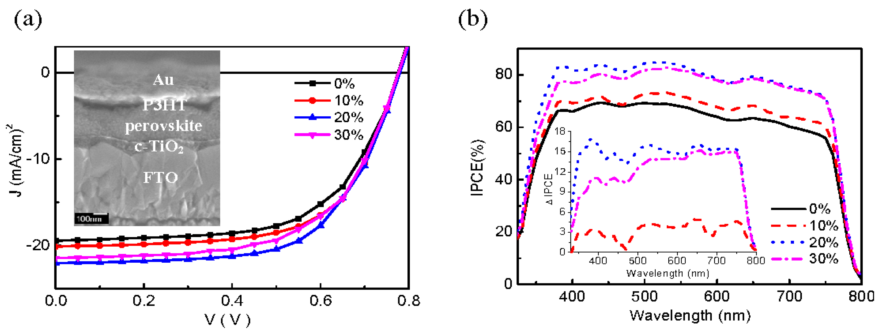
| 30 | 11.13 ± 2.76 | 20.87 ± 0.39 | 58.81 ± 4.22 | 0.68 ± 0.04 | 8.13 ± 0.98 |
| Ref. | Structure | Jsc (mA/cm2) | Jsc Enhancement (%) | Efficiency (ɳ %) | Efficiency Increase (%) | Mechanism |
|---|---|---|---|---|---|---|
| [132] | ITO/ PEDOT:PSS/MAPbI3/Ag NPs (79 nm)/PCBM/LiF/Al | 19.89 to 24.41 | 18.5 | 11.63 to 13.46 | 13.6% | The improved Jsc and overall device performance are attributed to enhanced absorption via LSPR and light optical path length increases |
| [133] | ITO/Au NPs (120 nm):QD- CsPbBr3/ PEDOT:PSS/MAPbI3/C60/Ag | 20.6 to 22.5 | 9 | 8.53 to 10.9 | 27.8 | LSPR excitation and light scattering |
| [134] | ITO/ PEDOT:PSS/MAPbI3/PCBM/Ag (nanocubes)/BCP/Ag | 19.5 to 21.4 | 9 | 11.9 to 13.3 | 10.5 | Plasmonic Ag nanocube coupling with Ag back electrode |
| [135] | ITO/TiO2/ZrN/SiO2 NPs (75 nm core/40 nm shell)/MASnI3/Spiro-OMeTAD/Au | 27 to 40.3 | 33 | 12.9 to 20 | 35.5 | Attributed to enhancement in the plasmonic surface plasmon’s directivity by the dielectric shell |
| ITO (150 nm)/TiO2 (40 nm)/TiN NPs (100nm)/MASnI3 (350 nm)/Spiro-OMeTAD (200 nm)/Au (100 nm) | 27 to 36.91 | 27 | 12.9 to 18.2 | 29 | Absorption enhancement due to plasmonic NP effects acts as a wave guide to direct sunlight by LSPR, forming surface plasmon polaritons (SPP) at the air/TiN interface | |
| ITO (150 nm)/TiO2 (40 nm)/ZrN NPs (100 nm)/MASnI3 (350 nm)/Spiro-OMeTAD (200 nm)/Au (100 nm) | 27 to 34.2 | 21 | 12.9 to 16.6 | 22.3 | Plasmonic resonance enhancement at NIR wavelengths | |
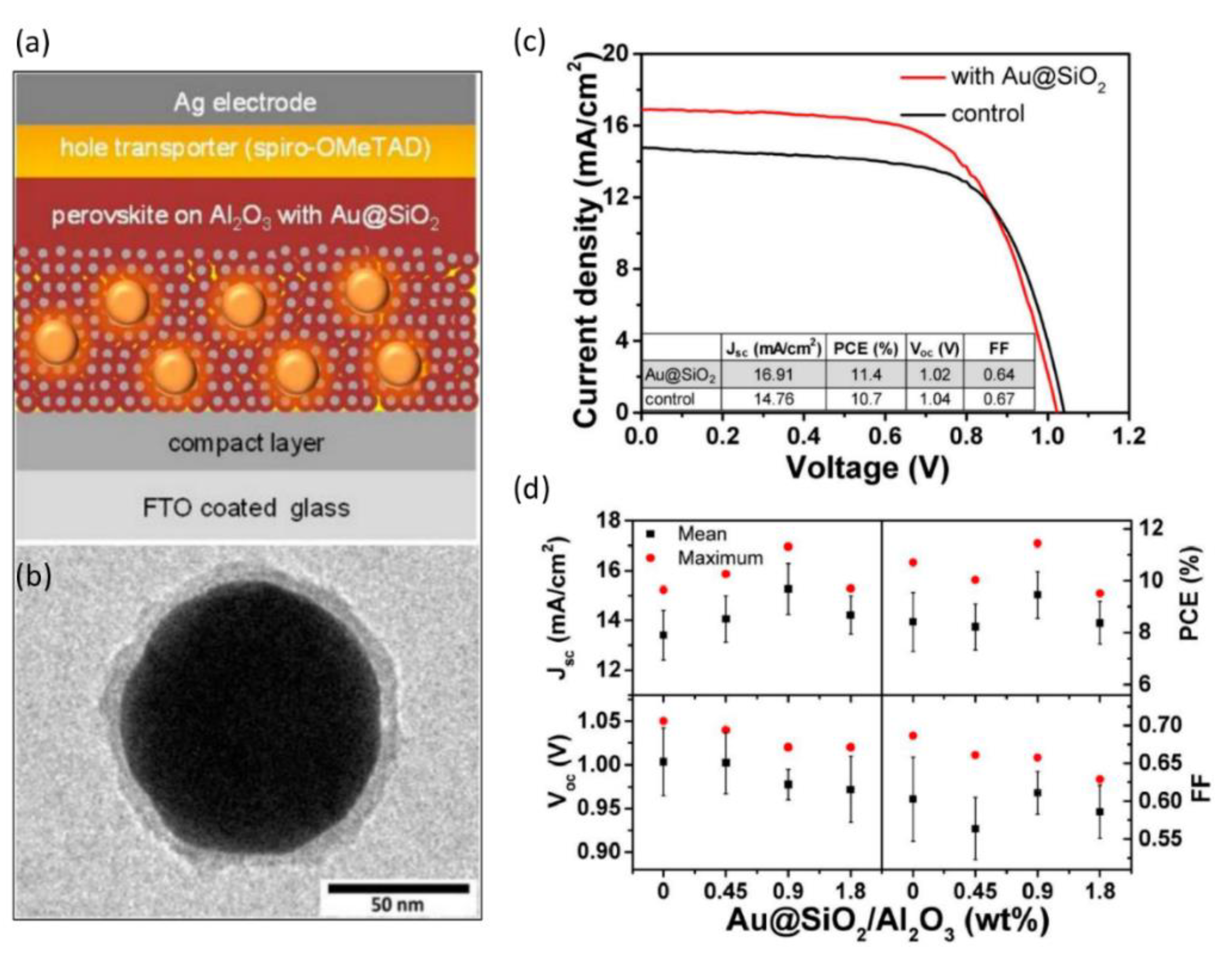
| [118] | FTO/TiO2 (50 nm)/Al2O3 (130 nm) with Au (80 nm)@SiO2 (8 nm) + MAPbI3/Spiro-OMeTAD/Ag | 14.76 to 16.91 | 13 | 10.7 to 11.4 | 6 | Attributed to enhanced photocurrent due to enhanced light absorption and plasmonic localized heating |
| [136] | FTO/Ag@TiO2/ Al2O3 + MAPbI3/Spiro-OMeTAD/Ag | 17.3 to 20.2 | 14.35 | 11.4 to 13.5 | 16 | Photocurrent improvement due to highly polarizable metallic NPs |
| [137] | FTO/c-TiO2/m-TiO2/Au-Ag alloy NPs (popcorn-shaped)/MAPbI3/Spiro-OMeTAD/Ag | 15.51 to 16.46 | 6 | 8.9 to 10.3 | 15.7% | Plasmonic popcorn NPs lead to faster charge transfer at the TiO2/perovskite interface, resulting in PCE increase |
| [138] | FTO/TiO2/SnO2/ CsFAMAPbI3Br3/Ag NR (buffer layer) Spiro-OMeTAD/Au | 21.08 to 22.18 | 5 | 18.50 to 20.29 | 9 | Ag NR increased the absorption by LSPR effect |
| [139] | ITO/TiO2/Au@TiO2 (NR)/MAPbI3/Spiro-OMeTAD/Au | 20.78 to 22.27 | 7 | 15.76 to 16.35 | 20.10 | Facilitated carrier transfer or separation in the presence of plasmonic NPs |
| [140] | FTO/PEDOT:PSS + Ag NPs/MAPbI3/ PCBM/Al | 15.06 to 15.47 | 3 | 4.17 to 5.58 | 25.3 | Plasmon induced enhanced absorption, superior photo-generated-carrier separation and transport by the Ag-NPs in the active perovskite material |
| [141] | FTO/c-TiO2/TiO2 (nanocolumns, NC)/Cs0.05(FA0.83MA0.17)0.95Pb(I0.83Br0.17)3/ SpiroOMeTAD/Au | 19.27 to 20.19 | 4.6 | 15.31 to 16.38 | 6.5 | TiO2 NC affects the performance of perovskite halide solar cells in terms of the charge transport, light-harvesting, and stability |
| [142] | FTO/c-TiO2/Au@TiO2 NPs embedded in p-TiO2/MAPbI3/Spiro-OMeTAD/Ag | 17.40 to 23.12 | 25 | 12.59 to 18.24 | 44 | Improvement is associated with exciton generation rate, enhanced exciton dissociation probability, as well as efficient carrier transfer/collection induced by the LSPR effect |
| [143] | ITO/ZnO/MAPbI3/Au (nanostars)/Spiro-OMeTAD/Ag | 17.43 to 18.21 | 4.3 | 11.98 to 13.97 | 14 | Absorption improved by Au NSs due to SPR and backscattering effects. |
| [144] | FTO/ZnO/ZnO NR/MAPbI3/spiro-OMeTAD/Au | 18.07 to 20.56 | 12.1 | 14.51 to 16.77 | ~14 | LSPR |
| [133] | 120AuNPs: Quantum Dots (QD)-CsPbBr3/ PEDOT:PSS/MAPbI3 | 20.6 to 22.5 | 8.4 | 8.53 to 10.9 | ~27.8 | LSPR excitation by resonance interaction |
| [145] | ITO/ PEDOT:PSS/ CH3NH3PbI3/ PC61BM/Al | 16.70 to 18.15 | 8 | 10.54 to 11.74 | ~10.22 | Sub-wavelength antenna due to LSPR excitation |
Publisher’s Note: MDPI stays neutral with regard to jurisdictional claims in published maps and institutional affiliations. |
© 2021 by the authors. Licensee MDPI, Basel, Switzerland. This article is an open access article distributed under the terms and conditions of the Creative Commons Attribution (CC BY) license (https://creativecommons.org/licenses/by/4.0/).
Share and Cite
Aïssa, B.; Ali, A.; El-Mellouhi, F. Oxide and Organic–Inorganic Halide Perovskites with Plasmonics for Optoelectronic and Energy Applications: A Contributive Review. Catalysts 2021, 11, 1057. https://doi.org/10.3390/catal11091057
Aïssa B, Ali A, El-Mellouhi F. Oxide and Organic–Inorganic Halide Perovskites with Plasmonics for Optoelectronic and Energy Applications: A Contributive Review. Catalysts. 2021; 11(9):1057. https://doi.org/10.3390/catal11091057
Chicago/Turabian StyleAïssa, Brahim, Adnan Ali, and Fedwa El-Mellouhi. 2021. "Oxide and Organic–Inorganic Halide Perovskites with Plasmonics for Optoelectronic and Energy Applications: A Contributive Review" Catalysts 11, no. 9: 1057. https://doi.org/10.3390/catal11091057
APA StyleAïssa, B., Ali, A., & El-Mellouhi, F. (2021). Oxide and Organic–Inorganic Halide Perovskites with Plasmonics for Optoelectronic and Energy Applications: A Contributive Review. Catalysts, 11(9), 1057. https://doi.org/10.3390/catal11091057