Review

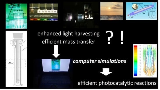
Computer Simulations of Photocatalytic Reactors

1
Institute of Chemical Technology and Engineering, Faculty of Chemical Technology, Poznan University of Technology, Berdychowo 4, 60-965 Poznan, Poland
2
Institute for Catalysis (ICAT), Hokkaido University, N21 W20, Sapporo 001-0021, Japan
*
Author to whom correspondence should be addressed.
Catalysts 2021, 11(2), 198; https://doi.org/10.3390/catal11020198
Submission received: 4 January 2021 / Revised: 22 January 2021 / Accepted: 29 January 2021 / Published: 3 February 2021

Abstract

:
Photocatalysis has been considered future technology for green energy conversion and environmental purification, including carbon dioxide reduction, water splitting, air/water treatment, and antimicrobial purposes. Although various photocatalysts with high activity and stability have already been found, the commercialization of photocatalytic processes seems to be slow; it is thought that the difficulty in scaling up photocatalytic processes might be responsible. Research on the design of photocatalytic reactors using computer simulations has been recently intensive. The computer simulations involve various methods of hydrodynamics, radiation, and mass transport analysis, including the Monte Carlo method, the approximation approach–P1 model, and computational fluid dynamics as a complex simulation tool. This review presents all of these models, which might be efficiently used for the scaling-up of photocatalytic reactors. The challenging aspects and perspectives of computer simulation are also addressed for the future development of applied photocatalysis.

Graphical Abstract

1. Introduction

Semiconductor photocatalysis, especially based on TiO2, has been known for over 40 years as a promising strategy to achieve aims such as environmental remediation (e.g., water treatment and air purification) and renewable energy (e.g., hydrogen production and carbon dioxide conversion to methane and light hydrocarbons) [1,2,3]. There have been many studies on photocatalysis, which can be divided into three main fields: development of new photocatalysts, fundamental studies on photocatalysis, and design of photocatalytic reactors [4,5,6,7,8,9].
Despite the constantly growing number of research studies in photocatalysis and some successful applications [10,11,12,13], a gap remains between research and commercialization. One of the main problems is the scaling-up of photocatalytic reactors [14]. Although some semi-pilot photoreactors exhibit similar or even better performance than laboratory ones, e.g., air-sparged hydrocyclone (ASH), due to irradiation of a thin and highly aerated liquid layer [8,15,16,17,18], the broad application of photocatalytic reactions needs a more systematic approach. This process requires the development of mathematical models such as the radiation absorption–scattering model, the radiation emission model, the kinetic model, and the fluid-dynamic model [19,20,21]. These models are the subdomains of a closely linked, complex numerical system based on differential equations [20]. The main point of the modeling procedure is the solution of the radiation transport equation (RTE). This equation depends on the specific geometry of the photocatalytic reactor and the type of light source [22,23]. The RTE solution requires the application of a proper mathematical model, such as the statistical Monte Carlo method [24,25,26,27] or approximation approach–P1 model [28,29,30]. Another important procedure is the discrete ordination method (DOM), which is recognized as an accurate and flexible procedure [19,22,31,32,33,34,35,36,37,38]. As a consequence of the increase in computing power, more research on the modeling of photocatalytic reactors also involves the concept of computational fluid dynamics (CFD). In general, the CFD method is widely used in the development of catalytic reactors and analysis of the systems involving fluid flows and heat transfer to understand the interactions of the catalyst with the surrounding reactive flow field in catalytic reactors (gas–solid, liquid–solid, and gas–liquid–solid) [39,40]. In the case of photocatalytic reactors, the CFD-aided modeling procedure also introduces the simulation of fluid flows (single- and multi-phase) and solves the RTE [32,37,41,42,43,44,45,46,47,48,49,50,51,52,53,54,55,56,57]. In the case of slurry photoreactor systems, there is the concept of local volumetric rate of energy absorption (LVREA), defined as the energy required by photons absorbed per time and volume inside the photoreactor. The photocatalytic reaction rate is the function of the LVREA [23,41]. The solution of the LVREA equation requires the analytical solution of RTE [58]. The commonly applied methods of RTE solution have already been mentioned above.
This review analyzes the present state of knowledge on computing methods in the design of photocatalytic reactors. The continuous development of computer-aided methods seems to be a necessary step to increase the number of successful large-scale applications of technologies based on photocatalytic processes. The aim of this work is to indicate the currently considered numerical methods and corresponding software solutions dedicated to the design of photocatalytic reactors. Notably, the most important advantages of computer-aided design are the substantial reduction in time and costs (less experimental trials) and the ability to study systems in which experiments are difficult or impossible to carry out.

2. Numerical Approaches Supporting Scaling-Up of Photocatalytic Reactors

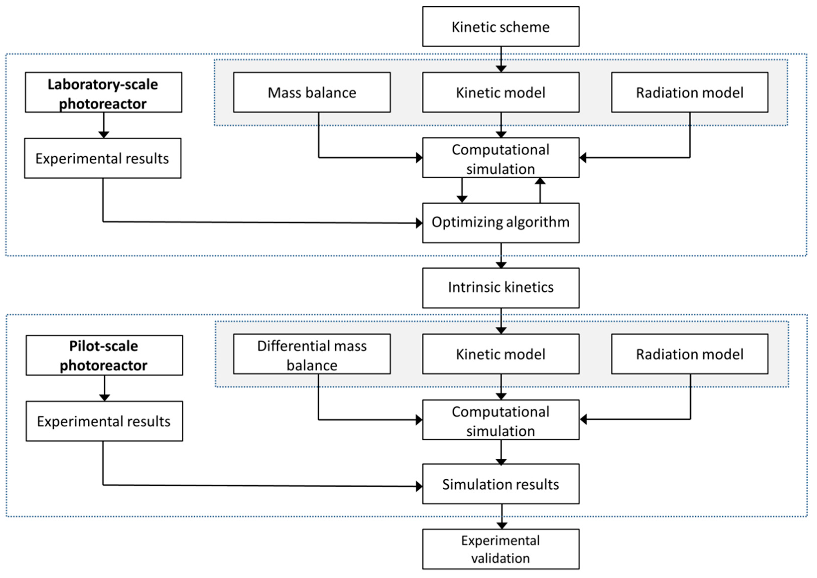
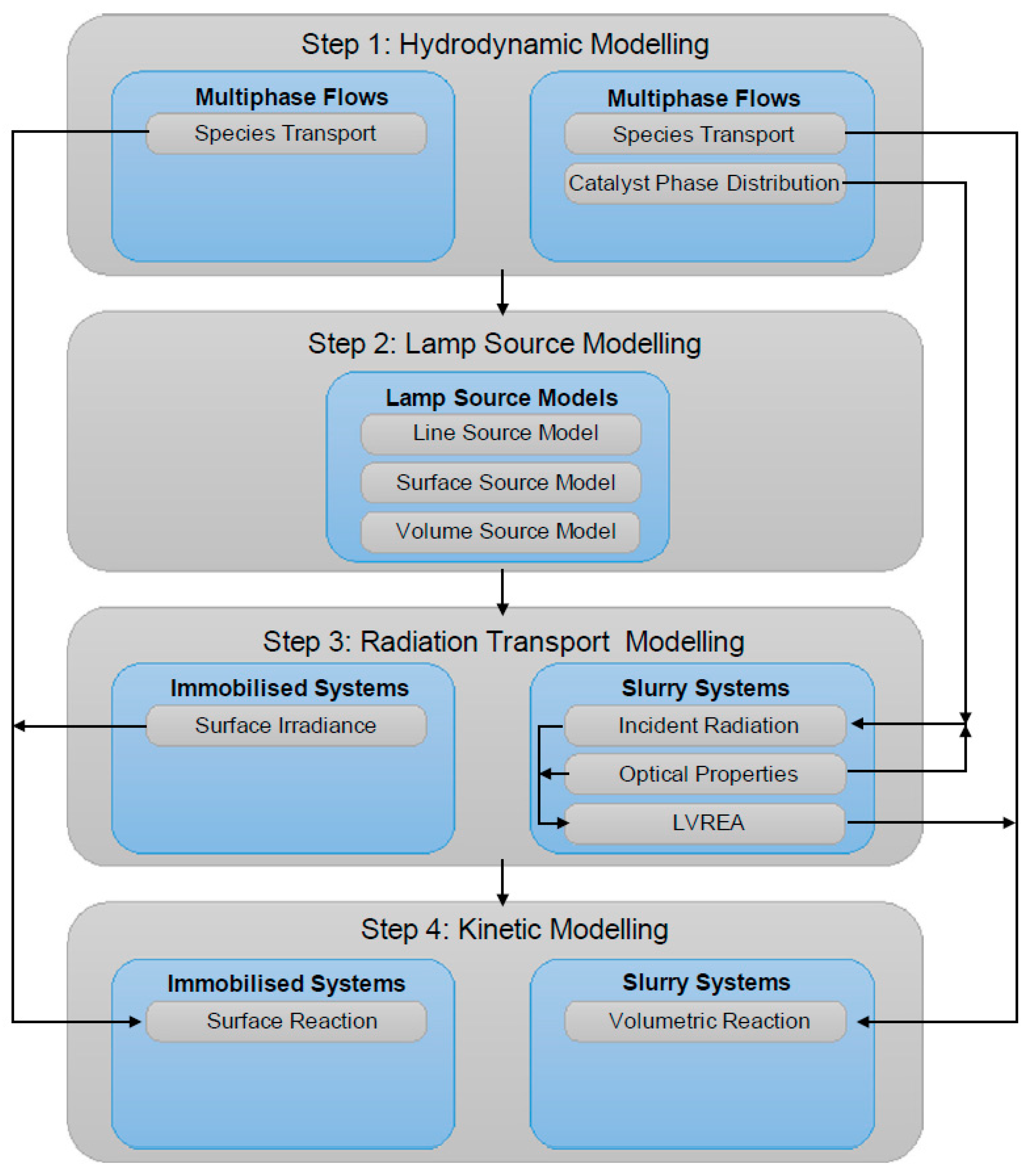
2.1. Scaling-Up Methodology of Photocatalytic Reactors

The traditional approach of the scaling-up procedure is based mostly on the empirical methodology, i.e., it starts from the laboratory set-ups, and then gradually, the photoreactor dimensions increase until it reaches the destination size specified for the particular practical application. This approach is, unfortunately, time-consuming and requires significant investments. Therefore, there is a consensus that the photoreactor design based on the mathematical models and the increased computing power of hardware might be useful in supporting the conventional scaling-up methodology [41,58,59,60,61]. Another approach for semi- and pilot-plan photoreactors has been applied, i.e., the use of other types of reactors as photoreactors after the addition of irradiation sources, e.g., an immersion of lamp(s) inside the reactor or an application of outside irradiation (both artificial and natural) [14]. For example, ASH, an efficient gas–liquid contactor used successfully for aeration, SO2 removal, flotation, and stripping [17,62,63], has shown high efficiency for oxidative decomposition of organic compounds when equipped with an immersed mercury lamp for both photolysis (UV and UV/H2O2) and photocatalytic (UV/TiO2) reactions [8,15,16]. Although this approach might result in the discovery of an efficient photocatalytic reactor, it is random, and more studies are needed for detailed characterization and further scaling-up of such photoreactors.
Satuf et al. proposed a methodology for scaling-up slurry photocatalytic reactors (the example of 4-chlorophenol photodegradation) [58]. A similar conception was formulated by the same research group for the photocatalytic reactor with TiO2 immobilized on the reactor walls for the removal of air pollutants [61]. Figure 1 shows the flow chart illustrating this scaling-up methodology, which consists of two main parts. The first (upper part of the scheme) relates to the derivation of an intrinsic kinetic expression that is independent of the present state of reactor configuration, radiation source, and experimental conditions, and corresponds to photocatalytic degradation of model compound in a laboratory scale reactor. The intrinsic kinetics is based on a detailed photocatalytic reaction scheme and introduces the factors resulting from irradiation conditions, the amount of photocatalyst, and initial compound concentration [58]. Furthermore, it would be stated as the rule that a carefully considered laboratory photoreactor could render a reaction kinetics expression without time dependence and with validity for the whole reactor, as long as it is possible by the provided method to safely extrapolate the results to more complex conditions. The estimation of kinetics parameters should be performed by introducing a nonlinear optimization program to adjust model predictions to the experimental data [61].
In the radiation model, the key point is to determine the effect of radiation absorption on the photocatalytic reaction rate. The simultaneous existence of absorption and scattering is important for radiation modeling (the RTE method). The mass balances of the photodegraded compound and the intermediate reaction products are considered to show the theoretical evolution of the involved species. They should include the data from the kinetic and radiation models [58]. In the second step (lower part of Figure 1), changing the process scale requires the usage of the same kinetic model for the reaction that was reported in the laboratory experiments. It is important to consider that the local volumetric rate of photon absorption (LVRPA) must be calculated from a different radiation balance, estimated for the larger photoreactor. Therefore, RTE should be applied to the new reactor to predict the LVRPA in a reaction space. The resulting expression should be included in the mass balance and, by the conduction of simulation procedure, to form the basis for calculating the reactor output variables. Subsequently, the validation of obtained results from the modeling procedure is necessary by comparing the experiments conducted in a larger (e.g., pilot) scale photoreactor [61].

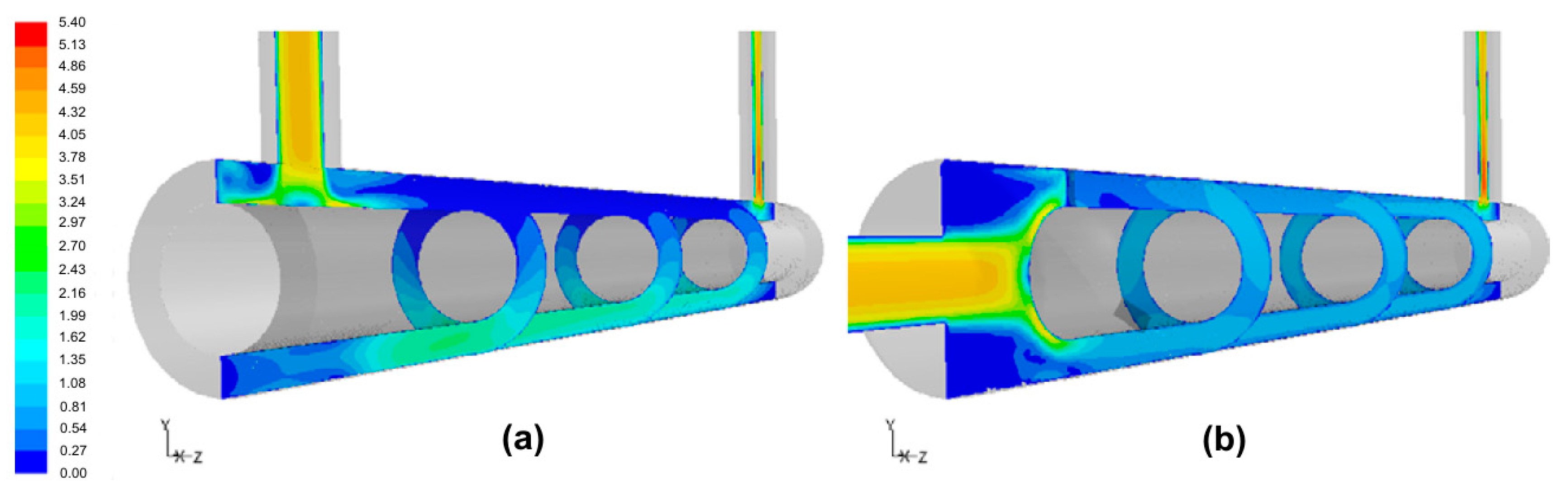
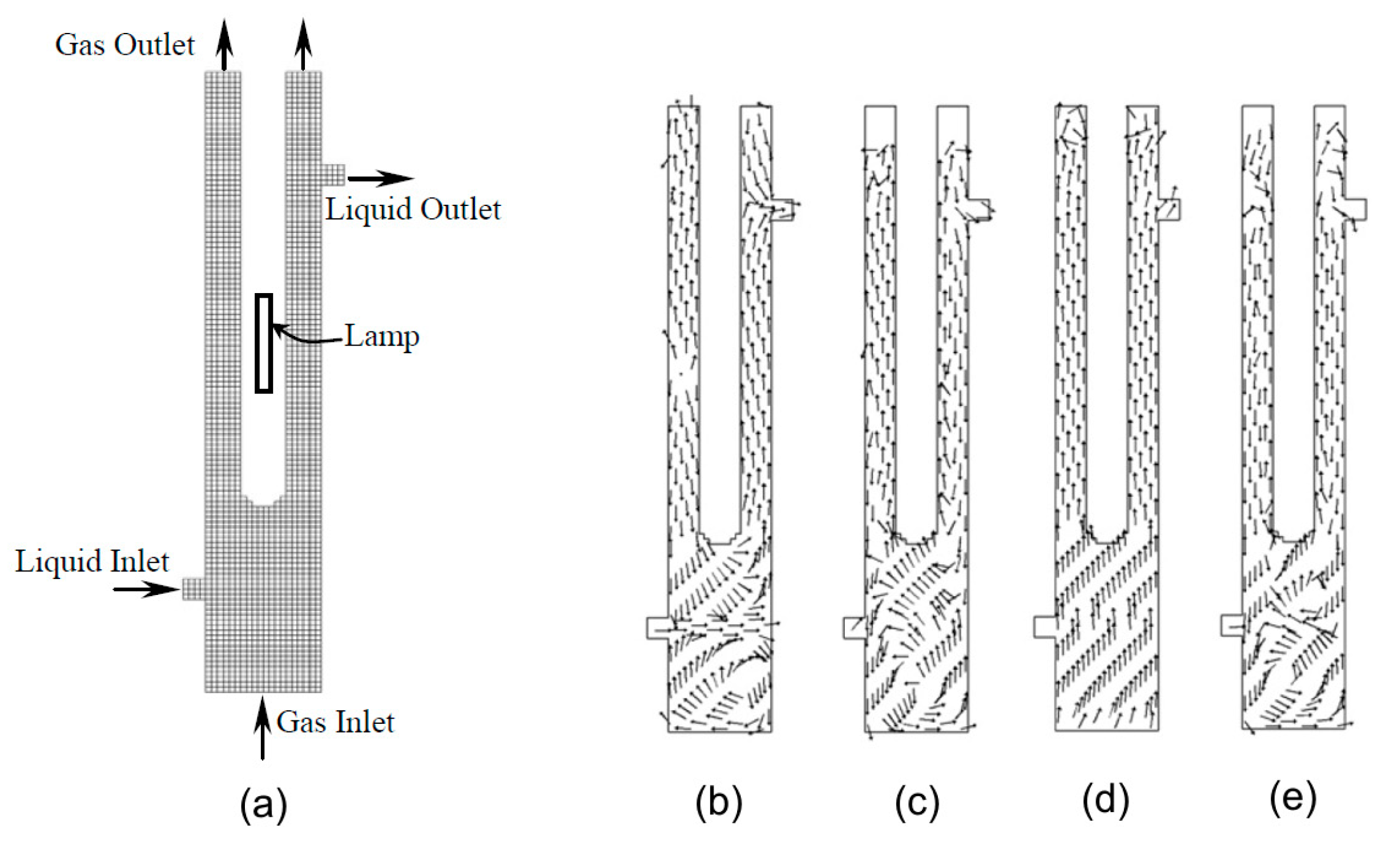
2.2. Hydrodynamics Modeling

The complex (integrated) photoreactor model should also consider the role of hydrodynamic conditions expressed by the momentum balance. For photocatalytic reactors, two types of conditions should be considered: (i) free-flow through the reaction system and (ii) the flow through the porous system [21,23,37]. The Navier–Stokes equations are used for the description of momentum balance at steady-state conditions. For the constant density and viscosity of the fluid, the continuity equation and the balance equation for momentum can be formulated [23,33]. The computational fluid dynamics method (CFD) is increasingly used to estimate the hydrodynamics and mass transfer to predict the velocity and concentration fields in photoreactors. Just as it underlies the CFD method, the Navier–Stokes equations as a set of differential equations describe the motion of viscous fluids [39]. These equations should be solved first before procuring the solution to the RTE [37].
There are different hydrodynamic models depending on the flow character (laminar/turbulent). If the fluid is assumed to be Newtonian, incompressible, non-reactive, with constant physical properties, and under laminar steady-state flow, it is possible to express the following equations [47]:
The continuity equation:
× ( U ) = 0
The equation of momentum conservation:
× ( ρ UU ) = P × τ
With the stress tensor:
τ = μ ( U + U T ) 2 3 μ × UI
The equation of species conservation:
× ( ρ Um i ) = × J i ,   i = 1 ,   2 ,   ,   N 1
The diffusive flux of species Ji can be estimated using Fick’s first law of diffusion:
J i = D m ( ρ m i )
In the above-mentioned equations, ρ is density, U is velocity, P is pressure, τ is viscous stress tensor, μ is molecular viscosity, I is unit tensor, mi is the mass fraction of species i, N is the total number of species, and Dm is the molecular diffusivity of species i in the mixture [47]. This model has been successfully applied in the CFD simulations of photocatalytic reactors [43,45,46,49,50,53,64,65,66,67,68]. This model is preferred for gas-phase photocatalytic reactions.
Considering the case of turbulent flow, under the same assumptions that were stated for laminar flow, the Reynolds-averaged Navier–Stokes (RANS) turbulence modeling approach requires to solve the following time-average equations [33]:
Mass conservation equation:
× ( U ¯ ) = 0
Momentum conservation equation:
× ( ρ UU ¯ + ρ uu ¯ ) = P ¯ × τ ¯
Species conservation equation:
× ( ρ U ¯ m i ¯ + ρ um i ¯ ) = × J i ¯   i = 1 ,   2 ,   ,   N 1  
The overbar indicates a time-average value, and u and m′i are fluctuating flow velocity and mass fraction of species i. The specification of the apparent stress gradient ( ρ UU ¯ ) is related to the adapted turbulence model [33]. Four hydrodynamic models are most often considered for modeling photoreactors: (a) standard k–ε model (S k–ε) [36,38,45,69,70], (b) the realizable k–ε model (R k–ε) [45,69], (c) the Reynolds stress model (RSM) [45,69], and (d) the low Reynolds number k–ε model (AKN—developed by Abe, Kondoh, and Nagano [21,45,71]). Duran et al. performed the CFD for a single-phase flow mass transfer prediction in annular reactors using different hydrodynamic models. Figure 2 shows fluid velocity magnitude differences between U- and L-type annular reactors [45].
For single-phase photoreactor systems, classical Navier–Stokes equations are efficient to calculate the hydrodynamic properties, but in the case of multi-phase flows, two main models are considered [72]: (a) Eulerian–Eulerian (E–E) and (b) Eulerian–Lagrangian (E–L) models. In the E–E model, the multiple phases are described as interpenetrating continua for which equations representing the conservation mass and momentum are solved. This model should be preferred due to its ability to simulate large-scale systems without excessive computational requirements. For the E–L approach, the trajectories of dispersed phase particles are simulated by solving an equation motion for each dispersed phase particle. The motion of the continuous phase is simulated by a conventional Eulerian approach [72]. Pareek et al. performed the simulation with an integrated model for a pilot-scale annular bubble column photocatalytic reactor using the CFD method [42]. They applied the conventional Eulerian model to simulate three-phase flow in the photoreactor. The model was verified using experimental data for photodegradation of Bayer liquor, and the adequacy of the adapted model was proven. Figure 3 shows the results of the simulation of this three-phase modeling study.
Another point is the aspect of stirring as one of the most important factors that is still underrated in the available computational studies. The performance of especially immobilized photocatalytic reactors is limited by the rate of mass transfer of the compounds to the photocatalyst layer. For example, Duran et al. [21] applied mass transfer promoters that increase the turbulence effect, such as repeated ribs on the internal wall of the reactor and static delta wing mixers placed in the middle of the reactor. A CFD simulation showed that repeated ribs improve the turbulence within the near-wall region, whereas delta wing mixers are responsible for increasing turbulence in the core flow [21].
An interesting example of CFD-aided studies on mass transfer improvement is the work concerning the Taylor vortex photocatalytic reactor [73,74]. The flow instability created in this type of reactor enhances the photocatalytic efficiency, as confirmed in both experimental and computational simulation studies.

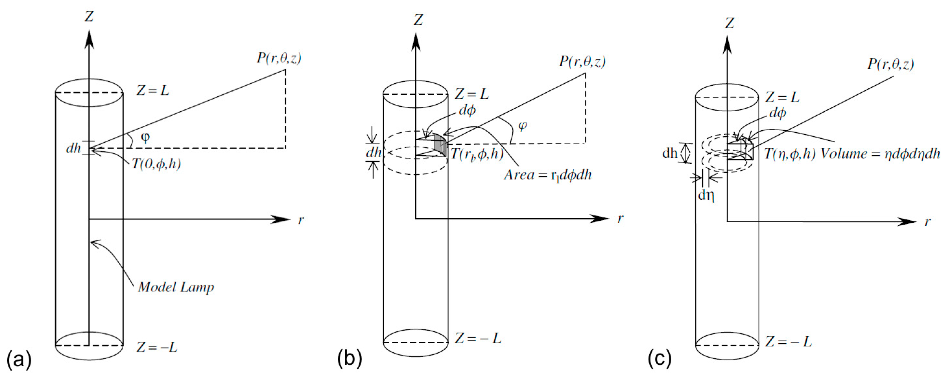
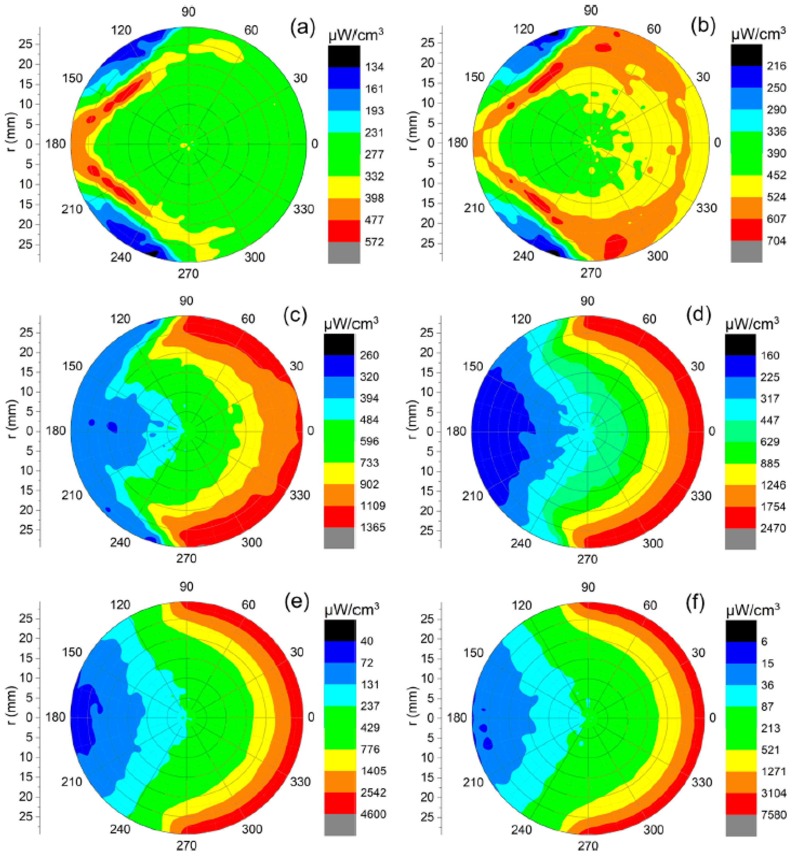
2.3. Lamp Emission and Radiation Modeling

It is possible to distinguish three types of illumination in photocatalytic reactors: (i) direct illumination, such as in immobilized photoreactors; (ii) with the lamp immersed in the reaction environment (slurry reactors); and (iii) with reflecting devices (parabolic or elliptical). This determines the necessity to create lamp emission models [72]. Adequately, three main emission models are considered: (a) the line source model, (b) the surface source model, and (c) the volume source model. The schematic presentations of these models are shown in Figure 4 [75].
The significance of lamp emission models is connected to the effects of reflection, refraction, and absorption of radiation prior to entering the reaction space being incorporated as boundary conditions during CFD-aided radiation modeling [72].
As already mentioned in the Introduction, the solution of the radiative (photon) transfer equation (RTE) is important for the modeling of the radiation field. For monochromatic radiation, this equation is defined as [33]:
dL ( r , s ) dz + ( κ + σ ) L ( r , s ) = j e ( r ) + σ 4 π 4 π L ( r ,   s   ) p (   s   s ) d   Ω   ,
where L is the photon radiance, r is the position vector, s is the propagation direction vector, z is the path length, κ is the absorption coefficient, σ is the scattering coefficient, je is the emission term, p is the phase function for the inscattering of photons, and Ω′ is the solid angle about the scattering vector s′. For photocatalytic reactors (slurry systems), due to light scattering in the presence of the photocatalyst, it is impossible to find an analytical solution for the RTE; therefore, the proper mathematical model is needed. The RTE solution provides the opportunity to calculate the local volumetric rate of energy absorption (LVREA) and the local volumetric rate of photon absorption (LVRPA). LVREA depends on the photon distribution in the reaction medium and is useful for the description of slurry-mode photoreactors. As defined in the photocatalytic process, photocatalytic reaction might proceed as the consequence of photocatalyst excitation by the light of a specified wavelength. The number of reacted molecules is proportional to the number of absorbed photons, which can be evaluated by LVREA. Therefore, this is a linkage between LVREA and photocatalytic efficiency.
The first common approach to solve RTE is the application of the Monte Carlo method. This is the class of methods involving statistical sampling to model complex chemical and physical phenomena. During the Monte Carlo simulation, RTE is not solved explicitly, but the trajectories and fates of all photons emitted from the lamp are traced. They are both decided with the usage of random numbers. Depending on the underlying hypotheses, various versions of the Monte Carlo method can be distinguished [76]. This method is often used to provide simulations of photoreactors [24,25,26,27]. For example, Akach et al. performed simulations of the light distribution in a solar photocatalytic bubble column reactor [27]. Figure 5 shows the polar plots of LVREA depending on photocatalyst loading. Computational simulations might help adjust optimal photocatalyst loading without performing appropriate experiments.
The P1 approximation method is another approach, which assumes that the angular distribution of radiation intensity is almost isotropic within the medium. Accordingly, the radiative energy that reaches any given point inside the reactor comes almost equally from all possible directions. This assumption is important in the view of the scattering phenomenon because it is possible to eliminate the directional behavior (from the radiation field) that originated from its sources [29]. This method has also been applied in photoreactor simulations [28,29,30].
The third important numerical method of RTE solution is the discrete ordination method (DOM). The DOM discretizes the infinite number of directions involved in Equation (9) to a finite number of directions, si, customized to the geometry of the system [29]. The presented description is too simplified because an important issue is to establish the proper boundary conditions, directions, and spatial discretization for any change in the reactor geometry. This flexible and accurate method has also been extensively studied for photocatalytic reactors [19,22,31,32,33,34,35,36,37,38].

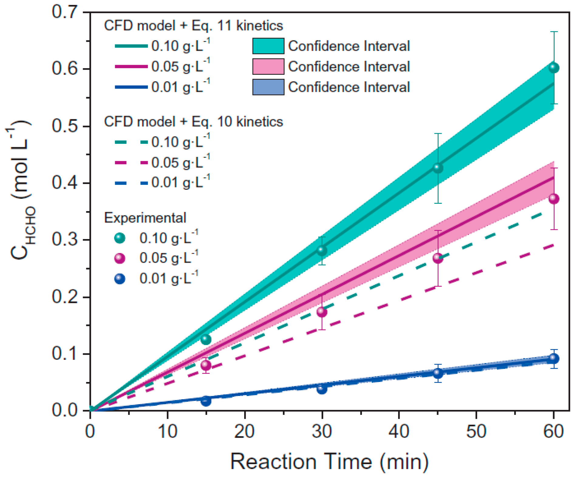
2.4. Kinetic Modeling

Most kinetic models are based on the Langmuir–Hinshelwood (L–H) rate form, which includes the phenomenon of the adsorption of the reagent (usually pollutant) on the photocatalyst surface [76,77]. In slurry photocatalytic systems, degradation of the compound depends on the operating conditions, such as pH, temperature, irradiance, oxygen concentration, initial concentration of the compound, and photocatalyst loading (Wcat) [72,78,79,80,81,82]:
r = k ( f [ P ] ) ,
k = f ( pH ,   T ,   E ,   [ O 2 ] ,   W cat ) ,
where f[P] is the function of the compound concentration and is usually of the first-order or L–H form. The following issue is to consider the effect of light intensity on the reaction rate. When the value of LVREA (corresponding to La) and its relation to light intensity are considered, then Equation (10) can be modified as follows [72,76]:
r = k ( L a ) m ( f [ P ] ) .
At large photocatalyst loading, the reaction rate usually decreases due to a higher electron-hole recombination rate. As a result, the volumetric rate of recombination is directly proportional to photocatalyst loading (Wcat). Then, the final form of the kinetic equation can be presented as [42,72]:
r = k 1 ( f [ P ] ) [ L a k 2 W cat ] .

3. Complex Photocatalytic Reactor Modeling Systems—The Available Software Tools

The above-described steps of photoreactor modeling might be presented as shown in Figure 6. The CFD method is an important tool to proceed with the complex modeling of photocatalytic reactors. It might combine all physicochemical phenomena involved in the process: fluid dynamics, species transport, radiation transport, and including its coupling with the chemical reaction rate, which has been described above. There are various CFD simulation frameworks available. Some of them are commercial, such as ANSYS® Fluent (ANSYS Inc., USA) and COMSOL Multiphysics® (COMSOL Inc., USA), and others are open-source CFD software, e.g., OpenFOAM and FEATFLOW.
A suitable example of complex modeling of photocatalytic reactors by available general-purpose CFD software (ANSYS® Fluent) is presented in the work of Casado et al. [83]. The simulation relates to the annular photocatalytic reactor. The analyzed model includes the description of hydrodynamics, radiation transfer, mass transport, and chemical reaction rate based on a mechanistic kinetic model. The results of photocatalytic activity, using methanol as a model compound, show agreement between model predictions and experimental data, with errors between 2% and 10%, depending on the photocatalyst loading (Figure 7) [83].
In the newest research performed by Moreno-SanSegundo et al., numerical simulations of three photocatalytic reactors were demonstrated: an annular reactor illuminated by a mercury fluorescent lamp, a tubular reactor coupled to a compound parabolic collector illuminated by sunlight, and a tubular photoreactor illuminated by LEDs [84]. The authors proposed a novel discrete ordinate model integrated with open-source OpenFOAM CFD software. The model predictions were successfully validated by comparing simulations conducted by commercial ANSYS® Fluent software (Figure 8). The proposed simulation method allows for substantial improvements, particularly in the modeling of the LED photoreactor. This is especially important from the point of view of the rapid development of this type of light source-driven photocatalytic reactors.
The application of available CFD software to perform the simulations of photocatalytic reactors is based on an adaptation of the existing simulation modules to conduct simulations of photoreactors. This configuration must be operated by a user familiar with CFD software; therefore, this might generate problems for non-experts in the design of photoreactors. Another approach is to create the complex simulation tool by direct programming of the proposed mathematical photocatalytic reactor models, but it can be difficult to perform for researchers because of the complexity of the project and the extended knowledge of programming languages. On the market, it is possible to find commercial simulation packages dedicated for the chemical industry, such as Aspen HYSYS® (Aspen Technology Inc., USA), but they do not have implemented modules for photocatalytic reactors.
Therefore, there is huge potential for complex simulation tools dedicated only for photocatalytic reactors. A promising example in this direction is PHOTOREAC, established as an open-access application developed in the graphical user interface of MATLAB® software [85]. Acosta-Herazo et al. performed the simulations with the PHOTOREAC environment, which includes three configurations of pilot-scale solar photoreactors: a flat plate photoreactor (FPP), a compound parabolic collector photoreactor (CPCP), and the offset multi-tubular photoreactor (OMTP). Each photoreactor system operates in recirculation with a flow-through mode with water passing through an external tank [85]. As a model photocatalyst, Evonik P25 TiO2 was selected [83], as it is commonly used as a standard due to one of the highest photocatalytic activities among titania photocatalysts [86,87,88,89].
The PHOTOREAC system consists of two main modules: (i) the photon absorption-scattering module (radiation field modeling) and (ii) the kinetic module (estimation of the radiation-independent kinetic parameters). In the case of the first module, a six-flux absorption-scattering model (SFM) was implemented. This is a simplified model, in which the main hypothesis is that scattering only occurs in the six Cartesian directions. Its application allows for short computational time and low mathematical complexity. The authors incorporated the SFM variant coupled with the Henyey–Greenstein scattering phase function (SFM-HG). Figure 9 shows a screenshot of the PHOTOREAC application window with a working photon absorption-scattering module [85,90].
It is thought that this promising open-access software approach, according to the authors’ recommendations [85], might be useful for introduction to photoreactor engineering in situations when a quantitative margin of error is still acceptable or qualitative results are the main aim of the work, and when the parametric space in the study is extensive. The authors are aware of the software limitations; thus, a plan to extend the capabilities of this CFD tool, dedicated for photocatalytic reactors, was proposed, e.g., the extension of simulation possibility to other photocatalysts and user-defined kinetics expressions [85].

4. Concluding Remarks

Heterogeneous photocatalysis, especially under natural solar radiation, seems to be the Earth’s future for energy conversion and environmental purification. Therefore, novel technologies of photocatalyst use must be developed for broad and easy application. Accordingly, the scaling-up of photocatalytic reactors is an important step to commercialize photocatalytic processes. The design of photocatalytic reactors with their particular complexity should be strictly interlinked with the proper computational tools for scaling-up. There are many processes and parameters that must be considered during the scaling-up procedure. Therefore, methods with a properly constructed system of mathematical models (hydrodynamics, radiation, and kinetics) based on the fundamentals of chemical engineering with an efficient algorithm should be constructed to provide reliable predictions of the performance of designed photoreactors. Furthermore, the constantly growing computing power of available hardware is another factor that should favor the development of these methods. Currently, the computational methods used in research on photoreactors are mainly based on general-purpose CFD tools, which are not strictly dedicated for this application. These simulations require much time and specific knowledge to be adopted in given conditions, to introduce the data, to launch proper models, and to perform the simulations. Nevertheless, the available research papers show that these computational tools provide increasingly accurate results. The latest successful and promising example of the PHOTOREAC MATHLAB®-based application outlines the recommended direction of research in this field, which is to design computational tools taking into account the specific character of photoreactors to make the simulation procedure simpler with an appropriate level of accuracy.

Author Contributions

M.J. and E.K. wrote the paper. All authors have read and agreed to the published version of the manuscript.

Funding

This research was funded by the Ministry of Science and Higher Education in Poland, subsidy for Poznan University of Technology, Faculty of Chemical Technology, and Yugo-Sohatsu Kenkyu, an Integrated Research Consortium on Chemical Sciences (IRCCS) project from the Ministry of Education and Culture, Sport, Science and Technology-Japan (MEXT).

Data Availability Statement

Not applicable.

Conflicts of Interest

The authors declare no conflict of interest.

References

  1. Bahnemann, D.W. Photocatalytic water treatment: Solar energy applications. Sol. Energy 2004, 77, 445–459. [Google Scholar] [CrossRef]
  2. Chen, X.; Shen, S.H.; Guo, L.J.; Mao, S.S. Semiconductor-based photocatalytic hydrogen generation. Chem. Rev. 2010, 110, 6503–6570. [Google Scholar] [CrossRef] [PubMed]
  3. Li, K.; Peng, B.S.; Peng, T.Y. Recent advances in heterogeneous photocatalytic CO2 conversion to solar fuels. ACS Catal. 2016, 6, 7485–7527. [Google Scholar] [CrossRef]
  4. Pelaez, M.; Nolan, N.T.; Pillai, S.C.; Seery, M.K.; Falaras, P.; Kontos, A.G.; Dunlop, P.S.M.; Hamilton, J.W.J.; Byrne, J.A.; O’Shea, K. A review on the visible light active titanium dioxide photocatalysts for environmental applications. Appl. Catal. B Environ. 2012, 125, 331–349. [Google Scholar] [CrossRef] [Green Version]
  5. Ohtani, B. Titania photocatalysis beyond recombination: A critical review. Catalysts 2013, 3, 942–953. [Google Scholar] [CrossRef] [Green Version]
  6. Janczarek, M.; Kowalska, E.; Ohtani, B. Decahedral-shaped anatase titania photocatalyst particles: Synthesis in a newly developed coaxial-flow gas-phase reactor. Chem. Eng. J. 2016, 289, 502–512. [Google Scholar] [CrossRef] [Green Version]
  7. Sundar, K.P.; Kanmani, S. Progression of photocatalytic reactors and it’s comparison: A review. Chem. Eng. Res. Des. 2020, 154, 135–150. [Google Scholar] [CrossRef]
  8. Kowalska, E.; Janczarek, M.; Hupka, J.; Grynkiewicz, M. H2O2/UV enhanced degradation of pesticides in wastewater. Water Sci. Technol. 2004, 49, 261–266. [Google Scholar] [CrossRef]
  9. Hoffmann, M.R.; Martin, S.T.; Choi, W.Y.; Bahnemann, D.W. Environmental applications of semiconductor photocatalysis. Chem. Rev. 1995, 95, 69–96. [Google Scholar] [CrossRef]
  10. Minero, C.; Pelizzetti, E.; Malato, S.; Blanco, J. Large solar plant photocatalytic water decontamination: Degradation of pentachlorophenol. Chemosphere 1993, 26, 2103–2119. [Google Scholar] [CrossRef]
  11. Malato, S.; Blanco, J.; Richter, C.; Curco, D.; Gimenez, J. Low-concentrating CPC collectors for photocatalytic water detoxification: Comparison with a medium concentrating solar collector. Water Sci. Technol. 1997, 35, 157–164. [Google Scholar] [CrossRef]
  12. Guillard, C.; Disdier, J.; Herrmann, J.M.; Lehaut, C.; Chopin, T.; Malato, S.; Blanco, J. Comparison of various titania samples of industrial origin in the solar photocatalytic detoxification of water containing 4-chlorophenol. Catal. Today 1999, 54, 217–228. [Google Scholar] [CrossRef]
  13. Blanco, J.; Malato, S.; Fernandez, P.; Vidal, A.; Morales, A.; Trincado, P.; Oliveira, J.C.; Minero, C.; Musci, M.; Casalle, C.; et al. Compound parabolic concentrator technology development to commercial solar detoxification applications. Sol. Energy 1999, 67, 317–330. [Google Scholar] [CrossRef]
  14. Kowalska, E.; Rau, S. Photoreactors for wastewater treatment: A review. Recent Pat. Eng. 2010, 4, 242–266. [Google Scholar] [CrossRef]
  15. Hupka, J.; Zaleska, A.; Janczarek, M.; Kowalska, E.; Gorska, P.; Aranowski, R. UV/VIS light-enhanced photocatalysis for water treatment and protection. In Soil and Water Pollution Monitoring, Protection and Remediation. NATO Science Series; Twardowska, I., Allen, H.E., Häggblom, M.M., Stefaniak, S., Eds.; Springer: Berlin/Heidelberg, Germany, 2006; pp. 351–367. [Google Scholar]
  16. Artuna, E.; Hupka, J. H2O2/UV/air oxidation of organic contaminants in the gas-sparged cyclone reactor. Cent. Eur. J. Public Health 2000, 8, 88–89. [Google Scholar] [PubMed]
  17. Lelinski, D.; Bokotko, R.; Hupka, J.; Miller, J.D. Bubble generation in swirl flow during air-sparged hydrocyclone flotation. Miner. Metall. Process. 1996, 13, 87–92. [Google Scholar] [CrossRef]
  18. Aranowski, R.; Wojewodka, P.; Zielinska-Jurek, A.; Bokotko, R.; Jungnickel, C. Spinning Fluids Reactor: A new design of a gas—Liquid contactor. Chem. Eng. Process. 2017, 116, 40–47. [Google Scholar] [CrossRef]
  19. Cassano, A.E.; Martin, C.A.; Brandi, R.J.; Alfano, O.M. Photoreactor analysis and design: Fundamentals and applications. Ind. Eng. Chem. Res. 1995, 34, 2155–2201. [Google Scholar] [CrossRef]
  20. Cassano, A.E.; Alfano, O.M. Reaction engineering of suspended solid heterogeneous photocatalytic reactors. Catal. Today 2000, 58, 167–197. [Google Scholar] [CrossRef]
  21. Duran, J.E.; Mohseni, M.; Taghipour, F. Computational modeling of UV photocatalytic reactors: Model development, evaluation, and application. Water Qual. Res. J. 2015, 50, 21–33. [Google Scholar] [CrossRef]
  22. Pareek, V.K.; Adesina, A.A. Light intensity distribution in a photocatalytic reactor using finite volume. AIChE J. 2004, 50, 1273–1288. [Google Scholar] [CrossRef]
  23. Sacco, O.; Vaiano, V.; Sannino, D. Main parameters influencing the design of photocatalytic reactors for wastewater treatment: A mini review. J. Chem. Technol. Biotechnol. 2020, 95, 2608–2618. [Google Scholar] [CrossRef]
  24. Alexiadis, A. 2-D radiation field in photocatalytic channels of square, rectangular, equilateral triangular and isosceles triangular sections. Chem. Eng. Sci. 2006, 61, 516–525. [Google Scholar] [CrossRef]
  25. Moreira, J.; Serrano, B.; Ortiz, A.; de Lasa, H. Evaluation of photon absorption in an aqueous TiO2 slurry reactor using Monte Carlo simulations and macroscopic balance. Ind. Eng. Chem. Res. 2010, 49, 10524–10543. [Google Scholar] [CrossRef]
  26. Akach, J.; Ochieng, A. Monte Carlo simulation of the light distribution inan annular slurry bubble column photocatalytic reactor. Chem. Eng. Res. Des. 2018, 129, 248–258. [Google Scholar] [CrossRef]
  27. Akach, J.; Kabuba, J.; Ochieng, A. Simulation of the light distribution in a solar photocatalytic bubble column reactor using the Monte Carlo method. Ind. Eng. Chem. Res. 2020, 59, 17708–17719. [Google Scholar] [CrossRef]
  28. Cuevas, S.A.; Arancibia-Bulnes, C.A.; Serrano, B. Radiation field in an annular photocatalytic reactor by the P1 approximation. Int. J. Chem. React. Eng. 2007, 5, A58. [Google Scholar] [CrossRef]
  29. Arancibia-Bulnes, C.A.; Jimenez, A.E.; Estrada, C.A. Development and modeling of solar photocatalytic reactors. Adv. Chem. Eng. 2009, 36, 185–227. [Google Scholar]
  30. Orozco, S.L.; Villafan-Vidales, H.I.; Arancibia-Bulnes, C.A. Photon absorption in a hybrid slurry photocatalytic reactor: Assessment of differential approximations. AIChE J. 2012, 58, 3256–3265. [Google Scholar] [CrossRef]
  31. Romero, R.L.; Alfano, O.M.; Cassano, A.E. Radiation field in an annular, slurry photocatalytic reactor. 2. Model and experiments. Ind. Eng. Chem. Res. 2003, 42, 2479–2488. [Google Scholar] [CrossRef]
  32. Denny, F.; Scott, J.; Pareek, V.; Peng, G.D.; Amal, R. CFD modelling for a TiO2-coated glass-bead photoreactor irradiated by optical fibres: Photocatalytic degradation of oxalic acid. Chem. Eng. Sci. 2009, 64, 1695–1706. [Google Scholar] [CrossRef]
  33. Duran, J.E.; Mohseni, M.; Taghipour, F. Computational fluid dynamics modeling of immobilized photocatalytic reactors for water treatment. AIChE J. 2011, 57, 1860–1872. [Google Scholar] [CrossRef]
  34. Pareek, V. Light intensity distribution in a dual-lamp photoreactor. Int. J. Chem. React. Eng. 2005, 3, A56. [Google Scholar] [CrossRef]
  35. Pareek, V.; Brungs, M.P.; Adesina, A.A. A new simplified model for light scattering in photocatalytic reactors. Ind. Eng. Chem. Res. 2003, 42, 26–36. [Google Scholar] [CrossRef]
  36. Qi, N.; Zhang, H.; Jin, B.; Zhang, K. CFD modelling of hydrodynamics and degradation kinetics in an annular slurry photocatalytic reactor for wastewater treatment. Chem. Eng. J. 2011, 172, 84–95. [Google Scholar] [CrossRef]
  37. Trujillo, F.J.; Safinski, T.; Adesina, A.A. CFD analysis of the radiation distribution in a new immobilized catalyst bubble column externally illuminated photoreactor. J. Sol. Energy Eng. 2007, 129, 27–36. [Google Scholar] [CrossRef]
  38. Trujillo, F.J.; Safinski, T.; Adesina, A.A. Oxidative photomineralization of dichloroacetic acid in an externally-irradiated rectangular bubble tank reactor: Computational fluid dynamics modeling and experimental verification studies. Ind. Eng. Chem. Res. 2010, 49, 6722–6734. [Google Scholar] [CrossRef]
  39. Klenov, O.P.; Noskov, A.S. Computational fluid dynamics in the development of catalytic reactors. Catal. Ind. 2011, 3, 331–349. [Google Scholar] [CrossRef]
  40. Hettel, M.; Worner, M.; Deutschmann, O. Computational fluid dynamics of catalytic reactors. In Handbook of Materials Modeling; Andreoni, W., Yip, S., Eds.; Springer: Berlin/Heidelberg, Germany, 2018; pp. 1–34. [Google Scholar]
  41. Boyjoo, Y.; Ang, M.; Pareek, V. CFD simulation of a pilot scale slurry photocatalytic reactor and design of multiple-lamp reactors. Chem. Eng. Sci. 2014, 111, 266–277. [Google Scholar] [CrossRef]
  42. Pareek, V.K.; Cox, S.J.; Brungs, M.P.; Young, B.; Adesina, A.A. Computational fuid dynamic (CFD) simulation of a pilot-scale annular bubble column photocatalytic reactor. Chem. Eng. Sci. 2003, 58, 859–865. [Google Scholar] [CrossRef]
  43. Taghipour, F.; Mohseni, M. CFD simulation of UV photocatalytic reactors for air treatment. AIChE J. 2005, 51, 3039–3047. [Google Scholar] [CrossRef]
  44. Castrillon, S.R.V.; De Lasa, H. Performance evaluation of photocatalytic reactors for air purification using computational fluid dynamics (CFD). Ind. Eng. Chem. Res. 2007, 46, 5867–5880. [Google Scholar] [CrossRef]
  45. Duran, J.E.; Taghipour, F.; Mohseni, M. CFD modeling of mass transfer in annular reactors. Int. J. Heat Mass Transf. 2009, 52, 5390–5401. [Google Scholar] [CrossRef]
  46. Jarandehei, A.; De Visscher, A. Three-dimensional CFD model for a flat plate photocatalytic reactor: Degradation of TCE in a serpentine flow field. AIChE J. 2009, 55, 312–320. [Google Scholar] [CrossRef]
  47. Duran, J.E.; Mohseni, M.; Taghipour, F. Modeling of annular reactors with surface reaction using computational fluid dynamics (CFD). Chem. Eng. Sci. 2010, 65, 1201–1211. [Google Scholar] [CrossRef]
  48. Duran, J.E.; Mohseni, M.; Taghipour, F. Design improvement of immobilized photocatalytic reactors using a CFD-Taguchi combined method. Ind. Eng. Chem. Res. 2011, 50, 824–831. [Google Scholar] [CrossRef]
  49. Vincent, G.; Schaer, E.; Marquaire, P.M.; Zahraa, O. CFD modelling of an annular reactor, application to the photocatalytic degradation of acetone. Process Saf. Environ. Prot. 2011, 89, 35–40. [Google Scholar] [CrossRef]
  50. Kumar, J.; Bansal, A. CFD modeling of hydrodynamics and mass transfer of Rhodamine B in annular reactor. Heat Mass Transf. 2012, 48, 2069–2077. [Google Scholar] [CrossRef]
  51. Misstear, T.; Gill, L. CFD modeling of fixed photocatalytic inserts for a continuous flow reactor for water disinfection. J. Adv. Oxid. Technol. 2012, 15, 153–162. [Google Scholar] [CrossRef]
  52. Wang, Z.; Liu, J.; Dai, Y.; Dong, W.; Zhang, S.; Chen, J. CFD modeling of a UV-LED photocatalytic odor abatement process in a continuous reactor. J. Hazard. Mater. 2012, 215–216, 25–31. [Google Scholar] [CrossRef]
  53. Verbruggen, S.W.; Lenaerts, S.; Denys, S. Analytic versus CFD approach for kinetic modeling of gas phase photocatalysis. Chem. Eng. J. 2015, 262, 1–8. [Google Scholar] [CrossRef]
  54. Castedo, A.; Uriz, I.; Soler, L.; Gandia, L.M.; Llorca, J. Kinetic analysis and CFD simulations of the photocatalytic production of hydrogen in silicone microreactors from water-ethanol mixtures. Appl. Catal. B 2017, 203, 210–217. [Google Scholar] [CrossRef] [Green Version]
  55. Roegiers, J.; Van Walsem, J.; Denys, S. CFD- and radiation field modeling of a gas phase photocatalytic multi-tube reactor. Chem. Eng. J. 2018, 338, 287–299. [Google Scholar] [CrossRef]
  56. Tong, K.; Yang, L.; Du, X. Modelling of TiO2-based packing bed photocatalytic reactor with Raschig rings for phenol degradation by coupled CFD and DEM. Chem. Eng. J. 2020, 400, 125988. [Google Scholar] [CrossRef]
  57. Yusuf, A.; Palmisano, G. Three-dimensional CFD modelling of a photocatalytic parallel-channel microreactor. Chem. Eng. Sci. 2021, 229, 116051. [Google Scholar] [CrossRef]
  58. Satuf, M.L.; Brandi, R.J.; Cassano, A.E.; Alfano, O.M. Scaling-up of slurry reactors for the photocatalytic degradation of 4-chlorophenol. Catal. Today 2007, 129, 110–117. [Google Scholar] [CrossRef]
  59. Li Puma, G. Dimensionless analysis of photocatalytic reactors using suspended solid photocatalysts. Chem. Eng. Res. Des. 2005, 83, 820–826. [Google Scholar] [CrossRef]
  60. Ghafoori, S.; Mehrvar, M.; Chan, P.K. Photoreactor scale-up for degradation of aqueous poly(vinyl alcohol) using UV/H2O2 process. Chem. Eng. J. 2014, 245, 133–142. [Google Scholar] [CrossRef]
  61. Imobedorf, G.E.; Irazoqui, H.A.; Alfano, O.M.; Cassano, A.E. Scaling-up from first principles of a photocatalytic reactor for air pollution remediation. Chem. Eng. Sci. 2007, 62, 793–804. [Google Scholar] [CrossRef]
  62. Niewiadomski, M.; Hupka, J.; Bokotko, R.; Miller, J.D. Recovery of coke fines from fly ash by air sparged hydrocyclone flotation. Fuel 1999, 78, 161–168. [Google Scholar] [CrossRef]
  63. Bokotko, R.P.; Hupka, J.; Miller, J.D. Flue gas treatment for SO2 removal with air-sparged hydrocyclone technology. Environ. Sci. Technol. 2005, 39, 1184–1189. [Google Scholar] [CrossRef] [PubMed]
  64. Mohseni, M.; Taghipour, F. Experimental and CFD analysis of photocatalytic gas phase vinyl chloride (VC) oxidation. Chem. Eng. Sci. 2004, 59, 1601–1609. [Google Scholar] [CrossRef]
  65. Wang, X.; Tan, X.; TYu, T. Kinetic study of ozone photocatalytic decomposition using a thin film of TiO2 coated on a glass plate and the CFD modeling approach. Ind. Eng. Chem. Res. 2014, 53, 7902–7909. [Google Scholar] [CrossRef]
  66. Turolla, A.; Santoro, D.; de Bruyn, J.R.; Crapulli, F.; Antonelli, M. Nanoparticle scattering characterization and mechanistic modelling of UV-TiO2 photocatalytic reactors using computational fluid dynamics. Water Res. 2016, 88, 117–126. [Google Scholar] [CrossRef]
  67. Verbruggen, S.W.; Keulemans, M.; Van Walsem, J.; Tytgat, T.; Lenaerts, S.; Denys, S. CFD modeling of transient adsorption/desorption behavior in a gas phase photocatalytic fiber reactor. Chem. Eng. J. 2016, 292, 42–50. [Google Scholar] [CrossRef]
  68. van Walsem, J.; Verbruggen, S.W.; Modde, B.; Lenaerts, S.; Denys, S. CFD investigation of a multi-tube photocatalytic reactor in non-steadystate conditions. Chem. Eng. J. 2016, 304, 808–816. [Google Scholar] [CrossRef]
  69. Sozzi, D.A.; Taghipour, F. Computational and experimental study of annular photo-reactor hydrodynamics. Int. J. Heat Mass Transf. 2006, 27, 1043–1053. [Google Scholar] [CrossRef]
  70. Trujillo, F.J.; Lee, I.A.L.; Hsu, C.H.; Safinski, T.; Adesina, A.A. Hydrodynamically-enhanced light intensity distribution in an externally-irradiated novel aerated photoreactor: CFD simulation and experimental studies. Int. J. Chem. React. Eng. 2008, 6, A58. [Google Scholar] [CrossRef]
  71. Abe, K.; Kondoh, T.; Nagano, Y. A new turbulence model for predicting fluid flow and heat transfer in separating and reattaching flows-I. Flow field calculations. Int. J. Heat Mass Transf. 1994, 37, 139–151. [Google Scholar] [CrossRef]
  72. Boyjoo, Y.; Ang, M.; Pareek, V. Some aspects of photocatalytic reactor modeling using computational fluid dynamics. Chem. Eng. Sci. 2013, 101, 764–784. [Google Scholar] [CrossRef]
  73. Sengupta, T.K.; Kabir, M.F.; Ray, A.K. A Taylor vortex photocatalytic reactor for water purification. Ind. Eng. Chem. Res. 2001, 40, 5268–5281. [Google Scholar] [CrossRef]
  74. Dutta, P.K.; Ray, A.K. Experimental investigation of Taylor vortex photocatalytic reactor for water purification. Chem. Eng. Sci. 2004, 59, 5249–5259. [Google Scholar] [CrossRef]
  75. Pareek, V.; Chong, S.; Tade, M.; Adesina, A.A. Light intensity distribution in heterogenous photocatalytic reactors. Asia-Pac. J. Chem. Eng. 2008, 3, 171–201. [Google Scholar] [CrossRef]
  76. Ollis, D.F. Kinetics of liquid phase photocatalyzed reactions:  An illuminating approach. J. Phys. Chem. B 2005, 109, 2439–2444. [Google Scholar] [CrossRef] [PubMed]
  77. Sannino, D.; Vaiano, V.; Sacco, O.; Ciambelli, P. Mathematical modelling of photocatalytic degradation of methylene blue under visible light irradiation. J. Environ. Chem. Eng. 2013, 1, 56–60. [Google Scholar] [CrossRef]
  78. Kowalska, E.; Rau, S.; Ohtani, B. Plasmonic Titania Photocatalysts Active under UV and Visible-Light Irradiation: Influence of Gold Amount, Size, and Shape. J. Nanotechnol. 2012, 2012, 361853. [Google Scholar] [CrossRef] [Green Version]
  79. Markowska-Szczupak, A.; Wei, Z.S.; Kowalska, E. The Influence of the light-activated titania P25 on human breast cancer cells. Catalysts 2020, 10, 238. [Google Scholar] [CrossRef] [Green Version]
  80. Khedr, T.M.; El-Sheikh, S.M.; Ismail, A.A.; Kowalska, E.; Bahnemann, D.W. Photodegradation of Microcystin-LR Using Visible Light-Activated C/N-co-Modified Mesoporous TiO2 Photocatalyst. Materials 2019, 12, 1027. [Google Scholar] [CrossRef] [Green Version]
  81. Dabrowski, B.; Zaleska, A.; Janczarek, M.; Hupka, J.; Miller, J.D. Photo-oxidation of dissolved cyanide using TiO2 catalyst. J. Photochem. Photobiol. A 2002, 151, 201–205. [Google Scholar] [CrossRef]
  82. Burgeth, G.; Kisch, H. Photocatalytic and photoelectrochemical properties of titania-chloroplatinate(IV). Coord. Chem. Rev. 2002, 230, 41–47. [Google Scholar] [CrossRef]
  83. Casado, C.; Marugan, J.; Timmers, R.; Munoz, M.; van Grieken, R. Comprehensive multiphysics modeling of photocatalytic processes by computational fluid dynamics based on intrinsic kinetic parameters determined in a differential photoreactor. Chem. Eng. J. 2017, 310, 368–380. [Google Scholar] [CrossRef] [Green Version]
  84. Moreno-SanSegundo, J.; Casado, C.; Marugan, J. Enhanced numerical simulation of photocatalytic reactors with an improved solver for the radiative transfer equation. Chem. Eng. J. 2020, 388, 124183. [Google Scholar] [CrossRef]
  85. Acosta-Herazo, R.; Canaveral-Velasquez, B.; Perez-Giraldo, K.; Mueses, M.A.; Pinzon-Cardenas, M.H.; Machuca-Martinez, F. A MATLAB-based application for modeling and simulation of solar slurry photocatalytic reactors for environmental applications. Water 2020, 12, 2196. [Google Scholar] [CrossRef]
  86. Prieto-Mahaney, O.O.; Murakami, N.; Abe, R.; Ohtani, B. Correlation between photocatalytic activities and structural and physical properties of titanium(IV) oxide powders. Chem. Lett. 2009, 38, 238–239. [Google Scholar] [CrossRef]
  87. Ohtani, B.; Prieto-Mahaney, O.O.; Li, D.; Abe, R. What is Degussa (Evonik) P25? Crystalline composition analysis, reconstruction from isolated pure particles and photocatalytic activity test. J. Photochem. Photobiol. A 2010, 216, 179–182. [Google Scholar] [CrossRef] [Green Version]
  88. Wang, K.L.; Janczarek, M.; Wei, Z.S.; Raja-Mogan, T.; Endo-Kimura, M.; Khedr, T.M.; Ohtani, B.; Kowalska, E. Morphology- and crystalline composition-governed activity of titania-based photocatalysts: Overview and perspective. Catalysts 2019, 9, 1054. [Google Scholar] [CrossRef] [Green Version]
  89. Wang, K.L.; Wei, Z.S.; Ohtani, B.; Kowalska, E. Interparticle electron transfer in methanol dehydrogenation on platinum-loaded titania particles prepared from P25. Catal. Today 2018, 303, 327–333. [Google Scholar] [CrossRef]
  90. Acosta-Herazo, R.; Monterroza-Romero, J.; Mueses, M.A.; Machuca-Martinez, F.; Li Puma, G. Coupling the Six Flux Absorption–Scattering Model to the Henyey–Greenstein scattering phase function: Evaluation and optimization of radiation absorption in solar heterogeneous photoreactors. Chem. Eng. J. 2016, 302, 86–96. [Google Scholar] [CrossRef] [Green Version]
Figure 1. Flow chart of the scaling-up methodology of photocatalytic reactors. Adopted with permission from [61]. Copyright Elsevier, 2007.
Catalysts 11 00198 g001
Figure 2. Contours of velocity magnitude (m/s) in: (a) U-shape; and (b) L-shape annular reactor calculated using the R k–ε model. Reprinted with permission from [45]. Copyright Elsevier, 2009.
Catalysts 11 00198 g002
Figure 3. Three-phase CFD hydrodynamic modeling: (a) a cross-section of the 3D computational domain and grid; (b) liquid velocity vectors in the absence of airflow; (c) liquid velocity vectors with gas flow; (d) gas velocity vectors; and (e) TiO2 particle velocity vectors. Adopted with permission from [42]. Copyright Elsevier, 2003.
Catalysts 11 00198 g003
Figure 4. Lamp emission models: (a) line source model; (b) surface source model; (c) volume source model. Reprinted with permission from [75]. Copyright Wiley, 2008.
Catalysts 11 00198 g004
Figure 5. Polar plots of LVREA at different photocatalyst loadings: (a) 0.005; (b) 0.01; (c) 0.025; (d) 0.05; (e) 0.1; (f) 0.2 g/L. Reprinted with permission from [27]. Copyright American Chemical Society, 2020.
Catalysts 11 00198 g005
Figure 6. The sequential steps in the CFD modeling of photocatalytic reactors. Reprinted with permission from [72]. Copyright Elsevier, 2013.
Catalysts 11 00198 g006
Figure 7. Validation of CFD simulation results for an annular laboratory-scale photoreactor with experimental data using different photocatalyst loadings (0.01, 0.05, and 0.1 g L−1). Reprinted with permission from [83]. Copyright Elsevier, 2017.
Catalysts 11 00198 g007
Figure 8. Incident radiation contours in a central plane in a CPC (compound parabolic collector) solar photoreactor; OpenFOAM (top) and ANSYS® Fluent (bottom) simulations; emission to normal surface (A,B) and at 45° (C,D). No adsorption or scattering (A,C) and 0.25 g L−1 TiO2 (B,D). (E) Schematic representation of the analyzed plane. (F) Quadrature rotation in parallel sources. Reprinted with permission from [84]. Copyright Elsevier, 2020.
Catalysts 11 00198 g008
Figure 9. A radiation field simulation of a flat plate photoreactor (FPP) with SFM-HG. The window of PHOTOREAC software [85].
Catalysts 11 00198 g009
Publisher’s Note: MDPI stays neutral with regard to jurisdictional claims in published maps and institutional affiliations.

