
Techniques of Preparation of Thin Films: Catalytic Combustion


Abstract
:1. Introduction
2. History of Thin Films
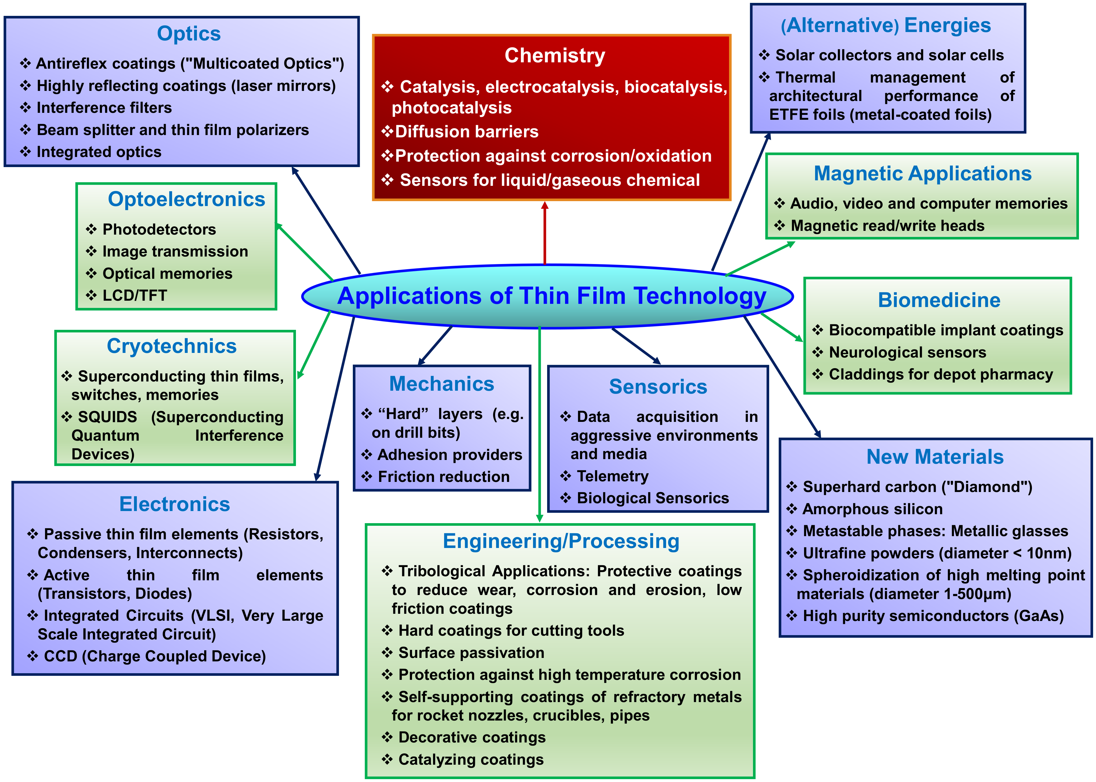
3. Applications of Thin Films
4. Techniques of Preparation of Thin Films
- The selection of the material that will be deposited (the target).
- The transport of the target to the substrate.
- The deposition of the target onto the substrate to form a thin film.
- The obtained thin film may be subjected to annealing or heat treatment processes.
4.1. Thin Film Growth and Nucleation
- Stranski-Krastanov (S-K) mechanism. The S-K mechanism combines both island and growth mechanisms. The adatoms begin to accumulate and form islands after an initial layer has grown.
4.2. Physical Deposition Process
4.2.1. Physical Vapor Deposition (PVD) Process
- The formation of vapor-phase species by evaporation, sputtering or ion bombardment of materials to be deposited.
- Migration from the source to the substrate.
- Film growth on the surface. The transported atom or molecule will start to nucleate across the substrate and grow by a number of processes.
A. Thermal (or Vacuum) Evaporation
- The formation of vapor by sublimation of the target at high temperature.
- The expulsion of vapor from the target and transportation to the substrate.
- The vapor condenses to form a solid thin film on the surface of the substrate. Several deposition cycles lead in thin film growth and nucleation [39].
- The Molecular Beam Epitaxy (MBE) Process
- b.
- The Reactive Evaporation (RE) Process
- c.
- The Activated Reactive Evaporation (ARE) Process
B. Arc Vapor Deposition
C. Ion Plating
D. Sputtering
- Direct Current (DC) Sputtering Uses of a Pair of Planar Electrodes
- b.
- Radio frequency (RF) Sputtering
- c.
- Magnetron
- d.
- Reactive Sputter Deposition.
4.2.2. Pulsed Laser Deposition (PLD)
4.3. Chemical Deposition Techniques
4.3.1. Chemical Vapor Deposition (CVD)
4.3.2. Thermal CVD
4.3.3. Laser CVD
4.3.4. Photon CVD
4.3.5. Plasma-Enhanced CVD (PECVD)
4.3.6. Pulsed CVD—ALD
4.3.7. Pulsed Spray Evaporation (PSE)
4.4. Plasma Electrolytic Oxidation (PEO)
4.4.1. Direct Current (DC)
4.4.2. Alternating Current (AC)
4.4.3. Pulsed Bipolar Current (PBC)
5. Thin Films Catalysts for Combustion Process
5.1. Thin Films in Noble Metal Catalysts
5.2. Thin Films in Transition Metal Oxide Catalysts
6. Conclusions
Funding
Acknowledgments
Conflicts of Interest
References
- Duprez, D.; Cavani, F. Handbook of Advanced Methods and Processes in Oxidation Catalysis; Imperial College Press: London, UK, 2014. [Google Scholar]
- Ojala, S.; Pitkäaho, S.; Laitinen, T.; Laitinen, T.; Koivikko, N.N.; Brahmi, R.; Gaalova, J.; Matejova, L.; Kucherov, A.; Paivarinta, S.; et al. Catalysis in VOC abatement. Top. Catal. 2011, 54, 1224–1256. [Google Scholar] [CrossRef]
- Lintz, H.G.; Pentenero, A.; Le Goff, P. Étude par spectrométrie de masse de la combustion hétérogène des vapeurs organiques sur platine. J. Chim. Phys. 1962, 59, 933–940. [Google Scholar] [CrossRef]
- Devore, P.; Eyrand, C.; Prettre, M. Combustion du méthane et de l’hydrogène sur platine incandescent: Transfert d’énergie et mécanisme de la reaction. Comptes Rendus Acad. Sci. 1958, 246, 1200. [Google Scholar]
- Firth, J.G.; Holland, H.B. Catalytic oxidation of methane over noble metals. Trans. Faraday Soc. 1969, 65, 1121–1127. [Google Scholar] [CrossRef]
- Cullis, C.F.; Nevell, T.G.; Trimm, D.L. Role of the catalyst support in the oxidation of methane over palladium. J. Chem. Soc. Faraday Trans. 1972, 68, 1406–1412. [Google Scholar] [CrossRef]
- McCarty, J.G.; Malukhin, G.; Poojary, D.M.; Datye, A.K.; Xu, Q. Thermal Coarsening of Supported Palladium Combustion Catalysts. J. Phys. Chem. B 2005, 109, 2387–2391. [Google Scholar] [CrossRef] [PubMed]
- Farrauto, R.J. Low-Temperature Oxidation of Methane. Science 2012, 337, 659–660. [Google Scholar] [CrossRef]
- Thirumalai, J. The Prominence of Thin Film Science in Technological Scale. In Thin Film Processes—Artifacts on Surface Phenomena and Technological Facets; Thirumalai, J., Ed.; IntechOpen, Open Research Library: London, UK, 2017. [Google Scholar]
- Greene, J.E. Tracing the 5000-year recorded history of inorganic thin films from 3000 BC to the early 1900s AD. Appl. Phys. Rev. 2014, 1, 041302. [Google Scholar] [CrossRef] [Green Version]
- Greene, J.E. Tracing the 4000-year recorded history of organic thin films: From monolayers on liquids to multilayers on solids. Appl. Phys. Rev. 2015, 2, 011101. [Google Scholar] [CrossRef]
- Greene, J.E. Organic thin films: From monolayers on liquids to multilayers on solids. Phys. Today 2014, 67, 43. [Google Scholar] [CrossRef] [Green Version]
- Lehner, M. The Complete Pyramids: Solving the Ancient Mysteries; Thames and Hudson, Ltd.: London, UK, 1997. [Google Scholar]
- Baker, R.F.; Baker, C.F. Ancient Egyptians: People of the Pyramids; Oxford University: London, UK, 2001. [Google Scholar]
- Ades, H. A Traveler’s History of Egypt; Interlink Books: Northampton, MA, USA, 2007. [Google Scholar]
- Harrell, J.A.; Brown, V.M. The world’s oldest surviving geological map: The 1150 BC Turin papyrus from Egypt. J. Geol. 1992, 100, 3–18. [Google Scholar] [CrossRef]
- Harrell, J.A.; Brown, V.M. The oldest surviving topographical map from ancient Egypt (Turin Papyri 1879, 1899 and 1969). J. Am. Res. Cent. Egypt 1992, 29, 81–105. [Google Scholar] [CrossRef]
- Notton, J.F.H. Ancient Egyptian gold refining. Gold Bull. 1974, 7, 50–56. [Google Scholar] [CrossRef] [Green Version]
- Hunt, L.B. The oldest metallurgical handbook. Gold Bull. 1976, 9, 24–31. [Google Scholar] [CrossRef] [Green Version]
- Zweibel, K. Thin films: Past, Present, Future. Natl. Tech. Inf. Serv. 1995, 3, 279–293. [Google Scholar]
- James, T.G.H. Gold technology in ancient Egypt. Gold Bull. 1972, 5, 38–42. [Google Scholar] [CrossRef] [Green Version]
- Darque-Ceretti, E.; Felder, E.; Aucouturier, M. Foil and leaf gilding on cultural artifacts; forming and adhesion. Rev. Mater. 2011, 16, 540–559. [Google Scholar] [CrossRef]
- Lechtman, H. Pre-Columbian surface metallurgy. Sci. Am. 1984, 250, 56–63. [Google Scholar] [CrossRef]
- Mallory, G.O.; Hajdu, J.B. Electroless Plating: Fundamentals and Applications; William Andrew Publishing: Norwich, NY, USA, 1990. [Google Scholar]
- Ingo, G.M.; Guida, G.; Angelini, E.; Carlo, G.D.; Mezzi, A.; Padeletti, G. Ancient Mercury-Based Plating Methods: Combined Use of Surface Analytical Techniques for the Study of Manufacturing Process and Degradation Phenomena. Acc. Chem. Res. 2013, 46, 2365–2375. [Google Scholar] [CrossRef] [PubMed]
- Brunetti, B.G.; Sgamellotti, A.; Clark, A.J. Advanced Techniques in Art Conservation. Acc. Chem. Res. 2010, 43, 693–694. [Google Scholar] [CrossRef]
- Green, J.E. Tracing the recorded history of thin-film sputter deposition: From the 1800s to 2017. J. Vac. Sci. Technol. A 2017, 35, 05C204. [Google Scholar] [CrossRef] [Green Version]
- Violi, I.L.; Zelcer, A.; Bruno, M.M.; Luca, V.; Soler-Illia, G.J.A.A. Gold Nanoparticles Supported in Zirconia−Ceria Mesoporous Thin Films: A Highly Active Reusable Heterogeneous Nanocatalyst. ACS Appl. Mater. Interfaces 2015, 7, 1114–1121. [Google Scholar] [CrossRef] [PubMed]
- Di Valentin, C.; Del Vitto, A.; Pacchionni, G.; Abbet, S.; Worz, A.S.; Judai, K.; Heiz, U. Chemisorption and Reactivity of Methanol on MgO Thin Films. J. Phys. Chem. B 2002, 106, 11961–11969. [Google Scholar] [CrossRef]
- Klaus, S.; Louie, M.W.; Trotochaud, L.; Bell, A.T. Role of Catalyst Preparation on the Electrocatalytic Activity of Ni1-xFexOOH for the Oxygen Evolution Reaction. J. Phys. Chem. C 2015, 119, 18303–18316. [Google Scholar] [CrossRef] [Green Version]
- Belton, D.N.; Sun, Y.M.; White, J.M. Thin-Film Models of Strong Metal-Support Interaction Catalysts. Platinum on Oxidized Titanium. J. Phys. Chem. 1984, 88, 1690–1695. [Google Scholar] [CrossRef]
- Miller, E.L.; Rocheleau, R.E. Electrochemical Behavior of Reactively Sputtered Iron-Doped Nickel Oxide. J. Electrochem. Soc. 1997, 144, 3072–3077. [Google Scholar] [CrossRef]
- Corrigan, D.A. The Catalysis of the Oxygen Evolution Reaction by Iron Impurities in Thin-Film Nickel-Oxide Electrodes. J. Electrochem. Soc. 1987, 134, 377–384. [Google Scholar] [CrossRef]
- Cooper, V.R.; Kolpak, A.M.; Yourdshahyan, Y.; Rappe, A.M. Oxide supported metal thin film catalysts: The how and why. In Nanotechnology in Catalysis; Springer: New York, NY, USA, 2007; pp. 13–21. [Google Scholar]
- Ischenko, O.; Krishnamoorthya, S.; Valle, N.; Guillot, J.; Turek, P.; Fechete, I.; Lenoble, D. Investigating vapor phase growth of block copolymer templated titania nanoarrays. J. Phys. Chem. C 2016, 120, 7067–7076. [Google Scholar] [CrossRef]
- Stoian, M.; Rogé, V.; Lazar, L.; Maurer, T.; Védrine, J.C.; Marcu, I.C.; Fechete, I. Total Oxidation of Methane on Oxide and Mixed Oxide Ceria-Containing Catalysts. Catalysts 2021, 11, 427. [Google Scholar] [CrossRef]
- Stoerzinger, K.A.; Choi, W.S.; Jeen, H.; Lee, H.N.; Shao-Horn, Y. Role of Strain and Conductivity in Oxygen Electrocatalysis on LaCoO3 Thin Films. J. Phys. Chem. Lett. 2015, 6, 487–492. [Google Scholar] [CrossRef]
- Olayinka, O.A.; Akinlabi, E.; Oladijo, P.; Akinlabi, S.; Ude, A.U. Overview of thin film deposition techniques. AIMS Mater. Sci. 2019, 6, 174–199. [Google Scholar] [CrossRef]
- Mattox, D.M. Handbook of Physical Vapor Deposition (PVD) Processing; William Andrew Publishing: Norwich, NY, USA, 2010. [Google Scholar]
- Wasa, K.; Kitabatake, M.; Adachi, H. Thin Film Materials Technology: Sputtering of Control Compound Materials; Springer Science & Business Media: New York, NY, USA, 2004. [Google Scholar]
- Lewis, B.L.; Anderson, J.C. Nucleation and Growth of Thin Films; Academic Press: New York, NY, USA, 1978. [Google Scholar]
- Venables, J.A.; Spiller, G.D.T. Nucleation and growth of thin films. In Surface Mobilities on Solid Materials; Binh, V.T., Ed.; Springer: Boston, MA, USA, 1983; Volume 3, pp. 341–404. [Google Scholar]
- Lewis, B.; Campbell, D. Nucleation and initial-growth behavior of thin-film deposits. J. Vac. Sci. Technol. 1967, 4, 209–218. [Google Scholar] [CrossRef]
- Lane, G.E.; Anderson, J.C. The nucleation and initial growth of gold films deposited onto sodium chloride by ion-beam sputtering. Thin Solid Films 1975, 26, 5–23. [Google Scholar] [CrossRef]
- Martin, P. Introduction to Surface Engineering and Functionally Engineered Materials; Wiley-Scrivener: Beverly, MA, USA, 2011. [Google Scholar]
- Seshan, K. Handbook of Thin Film Deposition, 3rd ed.; William Andrew Publishing: Norwich, NY, USA, 2012. [Google Scholar]
- West, A.R. Solid State Chemistry and Its Applications, 2nd ed.; John Wiley & Sons: Singapore, 2014. [Google Scholar]
- Chopra, K.L. Thin Film Phenomena, 1st ed.; McGraw Hill: New York, NY, USA, 1969. [Google Scholar]
- Kelly, P.; Arnell, R. Magnetron sputtering: A review of recent developments and applications. Vacuum 2000, 56, 159–172. [Google Scholar] [CrossRef]
- Kelly, P.; Arnell, R.; Ahmed, W. Some recent applications of materials deposited by unbalanced magnetron sputiering. Surf. Eng. 1993, 9, 287–292. [Google Scholar] [CrossRef]
- Stokes, J. Production of Coated and Free-Standing Engineering Components Using the HVOF (High Velocity Oxy-Fuel) Process. Ph.D. Thesis, Dublin City University, Dublin, Ireland, 2003. [Google Scholar]
- Panjan, P.; Drnovšek, A.; Gselman, P.; Cekada, M.; Panjan, M. Review of Growth Defects in Thin Films Prepared by PVD Techniques. Coatings 2020, 10, 447. [Google Scholar] [CrossRef]
- Trajkovska-Petkoska, A.; Nasov, I. Surface engineering of polymers: Case study: PVD coatings on polymers. Zast. Mater. 2014, 55, 3–10. [Google Scholar] [CrossRef] [Green Version]
- Cao, G. Nanostructures and Nanomaterials: Synthesis, Properties and Applications, 2nd ed.; Imperial College Press: London, UK, 2004. [Google Scholar]
- Messier, M.; Giri, A.P.; Roy, R.A. Revised structure zone model for thin film physical structure. J. Vac. Sci. Technol. A 1983, 2, 500–503. [Google Scholar] [CrossRef]
- Ricciardi, S. Surface Chemical Functionalization Based on Plasma Techniques; Lambert Academics Publishing: Sunnyvale, CA, USA, 2012. [Google Scholar]
- Mattox, D.M. Atomistic Film Growth and Some Growth-Related Film Properties. In Handbook of Physical Vapor Deposition (PVD) Processing; William Andrew: Norwich, NY, USA, 1998; ISBN 978-0-8155-1422-0. [Google Scholar]
- Herman, M.A.; Sitter, H. Molecular Beam Epitaxy: Fundamentals and Current Status; Springer Science & Business Media: New York, NY, USA, 2012. [Google Scholar]
- Chen, Y.; Bagnall, D.; Koh, H.; Park, K.-T.; Hiraga, K.; Zhu, Z.; Yao, T. Plasma assisted molecular beam epitaxy of ZnO on c-plane sapphire: Growth and characterization. J. Appl. Phys. 1998, 84, 3912–3918. [Google Scholar] [CrossRef]
- Rinaldi, F. Basics of Molecular Beam Epitaxy (MBE). Annual Report 2002; Optoelectronics Department, University of Ulm: Ulm, Germany, 2002; pp. 1–8. [Google Scholar]
- Cho, A.Y.; Reinhart, F.K. MBE Technique for Fabricating Semiconductor Devices Having Low Series Resistance. U.S. Patent US 3915765 A, 28 October 1975. [Google Scholar]
- Mergel, D.; Buschendorf, D.; Eggert, S.; Grammes, R.; Samset, B. Density and refractive index of TiO2 films prepared by reactive evaporation. Thin Solid Films 2000, 371, 218–224. [Google Scholar] [CrossRef]
- Pulker, H.K.; Paesold, G.; Ritter, E. Refractive indices of TiO2 films produced by reactive evaporation of various titanium–oxygen phases. Appl. Opt. 1976, 15, 2986–2991. [Google Scholar] [CrossRef]
- Terashima, T.; Iijima, K.; Yamamoto, K.; Bando, Y.; Mazaki, H. Single-crystal YBa2Cu3O7−x thin films by activated reactive evaporation. Jpn. J. Appl. Phys. 1988, 27, L91. [Google Scholar] [CrossRef]
- Bunshah, R.; Raghuram, A. Activated reactive evaporation process for high rate deposition of compounds. J. Vac. Sci. Technol. 1972, 9, 1385–1388. [Google Scholar] [CrossRef]
- Bunshah, R. The activated reactive evaporation process: Developments and applications. Thin Solid Films 1981, 80, 255–261. [Google Scholar] [CrossRef]
- Wasa, K.; Hayakawa, S. Handbook of Sputter Deposition Technology; Noyes Publications: Park Ridge, NJ, USA, 1992. [Google Scholar]
- Wasa, K.; Kitabatake, M.; Adachi, H. Thin Film Processes. In Thin Film Materials Technology; Wasa, K., Kitabatake, M., Adachi, H., Eds.; William Andrew Publishing: Norwich, NY, USA, 2004; pp. 17–69. [Google Scholar]
- Baragiola, R.A. Sputtering: Survey of observations and derived principles. Philos. Trans. R. Soc. Lond. Ser. A Math. Phys. Eng. Sci. 2004, 362, 29–53. [Google Scholar] [CrossRef]
- Musil, J.; Baroch, P.; Vlcek, J.; Nam, K.H.; Han, J.G. Reactive magnetron sputtering of thin films: Present status and trends. Thin Solid Films 2005, 475, 208–218. [Google Scholar] [CrossRef]
- Safi, I. Recent aspects concerning DC reactive magnetron sputtering of thin films: A review. Surf. Coat. Technol. 2000, 127, 203–219. [Google Scholar] [CrossRef]
- Leydecker, S. Nano Materials. In Architecture, Interior Architecture and Design; Springer Science and Business Media: Birkhauser, Switzerland, 2008; ISBN 3764379952. [Google Scholar]
- Phillips, R.W.; Raksha, V. Methods for Producing Enhanced Interference Pigments. U.S. Patent US 6524381 B2, 25 February 2003. [Google Scholar]
- Schultz, P.G.; Xiang, X.; Goldwasser, I.; Briceno, G.; Sun, X.-D.; Wang, K.-A. Combinatorial Synthesis and Screening of Non-Biological Polymers. U.S. Patent US 7034091, 25 April 2006. [Google Scholar]
- Seyfert, U.; Heisig, U.; Teschner, G. 40 Years of Industrial Magnetron Sputtering in Europe. SVC Bull. Fall 2015, 22–26. [Google Scholar]
- Seshan, K. Handbook of Thin-Film Deposition Processes and Techniques, Principles, Methods, Equipment and Applications; Noyes Publications/William Andrew Publishing: Norwich, NY, USA, 2001. [Google Scholar]
- Teixeira, V.; Cui, H.; Meng, L.; Fortunato, E.; Martins, R. Amorphous ITO thin films prepared by DC sputtering for electrochromic applications. Thin Solid Films 2002, 420, 70–75. [Google Scholar] [CrossRef]
- Utsumi, K.; Iigusa, H.; Tokumaru, R.; Song, P.K.; Shigesato, Y. Study on In2O3–SnO2 transparent and conductive films prepared by d.c. sputtering using high density ceramic targets. Thin Solid Films 2003, 445, 229–234. [Google Scholar] [CrossRef]
- Gómez, A.; Galeano, A.; Saldarriaga, W.; Arnache, O.; Moran, O. Deposition of YBaCo4O7+δ thin films on (001)-SrTiO3 substrates by dc sputtering. Vacuum 2015, 119, 7–14. [Google Scholar] [CrossRef]
- Cash, J.H., Jr.; Cunningham, J.A. Rf Sputtering Method. U.S. Patent 3677924, 18 July 1972. [Google Scholar]
- You, T.; Niwa, O.; Tomita, M.; Ando, H.; Suzuki, M.; Hirono, S. Characterization and electrochemical properties of highly dispersed copper oxide/hydroxide nanoparticles in graphite-like carbon films prepared by RF sputtering method. Electrochem. Commun. 2002, 4, 468–471. [Google Scholar] [CrossRef]
- Torng, C.; Sivertsen, J.M.; Judy, J.H.; Chang, C. Structure and bonding studies of the C: N thin films produced by rf sputtering method. J. Mater. Res. 1990, 5, 2490–2496. [Google Scholar] [CrossRef]
- Constantin, D.G.; Apreutesei, M.; Arvinte, R.; Marin, A.; Andrei, O.C.; Munteanu, D. Magnetron sputtering technique used for coatings deposition; technologies and applications. In Proceedings of the 7th International Conference on Materials Science and Engineering—BRAMAT 2011, Brasov, Romania, 24–26 February 2011. [Google Scholar]
- David, J.C. Making Magnetron Sputtering Work: Modelling Reactive Sputtering Dynamics, Part 1. SVC Bull. Fall 2015, 28–32. [Google Scholar]
- Arnell, R.D.; Kelly, P.J. Recent advances in magnetron sputtering. Surf. Coat. Tech. 1999, 112, 170–176. [Google Scholar] [CrossRef]
- Musil, J. Recent advances in magnetron sputtering technology. Surf. Coat. Tech. 1998, 100, 280–286. [Google Scholar] [CrossRef]
- Suzuki, Y.; Teranishi, K. Reactive Sputtering Method. U.S. Patent 7575661B2, 18 August 2009. [Google Scholar]
- Ishihara, M.; Li, S.; Yumoto, H.; Akashi, K.; Yde, Y. Control of preferential orientation of AlN films prepared by the reactive sputtering method. Thin Solid Films 1998, 316, 152–157. [Google Scholar] [CrossRef]
- Chistyakov, R. High-Power Pulsed Magnetron Sputtering. U.S. Patent 7147759B2, 12 December 2006. [Google Scholar]
- Kouznetsov, V.; Macák, K.; Schneider, J.M.; Helmersson, U.; Petrov, I. A novel pulsed magnetron sputter technique utilizing very high target power densities. Surf. Coat. Tech. 1999, 122, 290–293. [Google Scholar] [CrossRef]
- Sarakinos, K.; Alami, J.; Konstantinidis, S. High power pulsed magnetron sputtering: A review on scientific and engineering state of the art. Surf. Coat. Tech. 2010, 204, 1661–1684. [Google Scholar] [CrossRef]
- Alami, J.; Bolz, S.; Sarakinos, K. High power pulsed magnetron sputtering: Fundamentals and applications. J. Alloys Compd. 2009, 483, 530–534. [Google Scholar] [CrossRef]
- Wu, X.; Toe, C.-Y.; Su, C.; Ng, Y.-H.; Amal, R.; Scott, J. Preparation of Bi-based photocatalysts in the form of powdered particles and thin films: A review. J. Mater. Chem. A 2020, 8, 15302–15318. [Google Scholar] [CrossRef]
- Carlsson, J.; Martin, P.M. Chemical Vapor Deposition. In Handbook of Deposition Technologies for Films and Coatings: Science, Applications and Technology, 3rd ed.; Martin, P.M., Ed.; William Andrew Publishing: Boston, MA, USA, 2010; Chapter 7; pp. 314–363. [Google Scholar]
- Albetran, H.M.M. Synthesis and Characterisation of Nanostructured TiO2 for Photocatalytic Applications. Ph.D. Thesis, Curtin University, Perth, WA, Australia, 2016. [Google Scholar]
- Miller, T. An Investigation into the Growth and Characterisation of Thin Film Radioluminescent Phosphors for Neutron Diffraction Analysis. Ph.D. Thesis, Nottingham Trent University, Nottingham, UK, 2010. [Google Scholar]
- Pessoa, R.; Fraga, M.; Santos, L. Nanostructured thin films based on TiO2 and/or SiC for use in photoelectrochemical cells: A review of the material characteristics, synthesis and recent applications. Mat. Sci. Semicon. Proc. 2015, 29, 56–68. [Google Scholar] [CrossRef]
- Kommu, S.; Wilson, G.M.; Khomami, B. A Theoretical/Experimental Study of Silicon Epitaxy in Horizontal Single-Wafer Chemical Vapor Deposition Reactors. J. Electrochem. Soc. 2000, 147, 1538–1550. [Google Scholar] [CrossRef]
- Pedersen, H.; Elliott, S.D. Studying chemical vapor deposition processes with theoretical chemistry. Theor. Chem. Acc. 2014, 133, 1476. [Google Scholar] [CrossRef] [Green Version]
- Wang, D.N.; White, J.M.; Law, K.S.; Leung, C.; Umotoy, S.P.; Collins, S.K.; Adamik, J.A.; Perlov, I.; Maydan, D. Thermal CVD/PECVD reactor and Use for Thermal Chemical Vapor Deposition of Silicon Dioxide and In-Situ Multi-Step Planarized Process. U.S. Patent 5000113, 19 March 1991. [Google Scholar]
- Hirose, Y.; Terasawa, Y. Synthesis of diamond thin films by thermal CVD using organic compounds. Jpn. J. Appl. Phys. 1986, 25, L519. [Google Scholar] [CrossRef]
- Petzoldt, F.; Piglmayer, K.; Kräuter, W.; Bauerele, D. Lateral growth rates in laser CVD of microstructures. Appl. Phys. A 1984, 35, 155–159. [Google Scholar] [CrossRef]
- Sousa, P.; Silvestre, A.; Popovici, N.; Conde, O. Morphological and structural characterization of CrO2/Cr2O3 films grown by Laser-CVD. Appl. Surf. Sci. 2005, 247, 423–428. [Google Scholar] [CrossRef]
- Matsui, S. Three-dimensional nanostructure fabrication by focused-ion-beam chemical vapor deposition. J. Vac. Sci. Technol. B 2000, 18, 3181–3184. [Google Scholar] [CrossRef]
- Inoue, K.; Michimori, M.; Okuyama, M.; Hamakawa, Y. Low temperature growth of SiO2 thin film by double-excitation photo-CVD. Jpn. J. Appl. Phys. 1987, 26, 805. [Google Scholar] [CrossRef]
- Tanimoto, S.; Matsui, M.; Kamisako, K.; Kuroiwa, K.; Tarui, Y. Investigation on leakage current reduction of photo-CVD tantalum oxide films accomplished by active oxygen annealing. J. Electrochem. Soc. 1992, 139, 320–328. [Google Scholar] [CrossRef]
- Price, J.; Wu, S. Plasma Enhanced CVD. U.S. Patent 4692343, 8 September 1987. [Google Scholar]
- Li, Y.; Mann, D.; Rolandi, M.; Kim, W.; Ural, A.; Hung, S.; Javey, A.; Cao, J.; Wang, D.; Yenilmez, E.; et al. Preferential growth of semiconducting single-walled carbon nanotubes by a plasma enhanced CVD method. Nano Lett. 2004, 4, 317–321. [Google Scholar] [CrossRef]
- Hozumi, A.; Takai, O. Preparation of ultra water-repellent films by microwave plasma-enhanced CVD. Thin Solid Films 1997, 303, 222–225. [Google Scholar] [CrossRef]
- Graniel, O.; Weber, M.; Balme, S.; Miele, P.; Bechelany, M. Atomic layer deposition for biosensing applications. Biosens. Bioelectron. 2018, 122, 147–159. [Google Scholar] [CrossRef] [PubMed]
- Suntola, T.; Antson, J. Method for Producing Compound Thin Films. U.S. Patent 4058430, 15 November 1977. [Google Scholar]
- Guo, H.C.; Ye, E.; Li, Z.; Han, M.-Y.; Loh, X.J. Recent progress of atomic layer deposition on polymeric materials. Mat. Sci. Eng. C Mater. 2017, 70, 1182–1191. [Google Scholar] [CrossRef] [PubMed]
- George, S.M. Atomic layer deposition: An overview. Chem. Rev. 2009, 110, 111–131. [Google Scholar] [CrossRef] [PubMed]
- Miikkulainen, V.; Leskelä, M.; Ritala, M.; Puurunen, L.R. Crystallinity of inorganic films grown by atomic layer deposition: Overview and general trends. J. Appl. Phys. 2013, 113, 2. [Google Scholar] [CrossRef]
- Bohr, M.T.; Chau, R.S.; Ghani, T.; Mistry, K. The high-k solution. IEEE Spectr. 2007, 44, 29–35. [Google Scholar] [CrossRef]
- Yan, B.; Li, X.; Bai, Z.; Song, X.; Xiong, D.; Zhao, M.; Li, D.; Lu, S. A review of atomic layer deposition providing high performance lithium sulfur batteries. J. Power Sources 2017, 338, 34–48. [Google Scholar] [CrossRef]
- Ozer, N.; Lampert, C.M. Electrochromic characterization of sol–gel deposited coatings. Sol. Energy Mater. Sol. Cells 1998, 54, 147–156. [Google Scholar] [CrossRef]
- Niinisto, L.; Ritala, M.; Leskela, M. Synthesis of oxide thin films and overlayers by atomic layer epitaxy for advanced applications. Mater. Sci. Eng. B 1996, 41, 23–29. [Google Scholar] [CrossRef]
- Kim, H.; Lee, H.B.R.; Maeng, W.-J. Applications of atomic layer deposition to nanofabrication and emerging nanodevices. Thin Solid Films 2009, 517, 2563–2580. [Google Scholar] [CrossRef]
- Knez, M.; Nielsch, K.; Niinistö, L. Synthesis and Surface Engineering of Complex Nanostructures by Atomic Layer Deposition. Adv. Mater. 2007, 19, 3425–3438. [Google Scholar] [CrossRef]
- Szilágyi, I.M.; Nagy, D. Review on one-dimensional nanostructures prepared by electrospinning and atomic layer deposition. J. Phys. Conf. Ser. 2014, 559, 012010. [Google Scholar] [CrossRef]
- Devi, A. “Old Chemistries” for new applications: Perspectives for development of precursors for MOCVD and ALD applications. Coord. Chem. Rev. 2013, 257, 3332–3384. [Google Scholar] [CrossRef]
- Puurunen, R.L. A short history of atomic layer deposition: Tuomo Suntola’s atomic layer epitaxy. Chem. Vap. Depos. 2014, 20, 332–344. [Google Scholar] [CrossRef] [Green Version]
- Malygin, A.A.; Drozd, V.E.; Malkov, A.A.; Smirnov, V.M. From VB Aleskovskii’s “Framework” Hypothesis to the Method of Molecular Layering/Atomic Layer Deposition. Chem. Vap. Depos. 2015, 21, 216–240. [Google Scholar] [CrossRef]
- Leskelä, M.; Ritala, M. Atomic layer deposition (ALD): From precursors to thin film structures. Thin Solid Films 2002, 409, 138–146. [Google Scholar] [CrossRef]
- Chalker, P. Photochemical atomic layer deposition and etching. Surf. Coat. Technol. 2016, 291, 258–263. [Google Scholar] [CrossRef] [Green Version]
- Leskelä, M.; Ritala, M. Atomic Layer Deposition Chemistry: Recent Developments and Future Challenges. Angew. Chem. Int. Ed. Engl. 2003, 42, 5548–5554. [Google Scholar] [CrossRef] [PubMed]
- Ritala, M.; Leskelä, M. Atomic layer deposition. In Handbook of Thin Film Materials Volume 1: Deposition and Processing of Thin Films; Elsevier: Amsterdam, The Netherlands, 2002; Volume 1, pp. 103–159. [Google Scholar]
- Aaltonen, T.; Ritala, M.; Tung, Y.-L.; Chi, Y.; Arstila, K.; Meinander, K.; Leskela, M. Atomic layer deposition of noble metals: Exploration of the low limit of the deposition temperature. J. Mater. Res. 2004, 19, 3353–3358. [Google Scholar] [CrossRef] [Green Version]
- Johnson, R.W.; Hultqvist, A.; Bent, S.F. A brief review of atomic layer deposition: From fundamentals to applications. Mater. Today 2014, 17, 236–246. [Google Scholar] [CrossRef]
- Lim, B.S.; Rahtu, A.; Gordon, R.G. Atomic layer deposition of transition metals. Nat. Mater. 2003, 2, 749–754. [Google Scholar] [CrossRef] [PubMed]
- Weber, M.J.; Mackus, J.M.A.; Verheijen, A.M.; Longo, V.; Bol, A.A.; Kessels, M.M.W. Atomic layer deposition of high-purity palladium films from Pd(hfac)2 and H2 and O2 Plasmas. J. Phys. Chem. C 2014, 118, 8702–8711. [Google Scholar] [CrossRef]
- Hämäläinen, J.; Ritala, M.; Leskelä, M. Atomic Layer Deposition of Noble Metals and Their Oxides. Chem. Mater. 2014, 26, 786–801. [Google Scholar] [CrossRef]
- Kim, H. Atomic layer deposition of metal and nitride thin films: Current research efforts and applications for semiconductor device processing. J. Vac. Sci. Technol. B 2003, 21, 2231. [Google Scholar] [CrossRef] [Green Version]
- Weber, M.; Koonkaew, B.; Balme, S.; Utke, I.; Picaud, F.; Iatsunskyi, I.; Coy, E.; Miele, P.; Bechelany, M. Boron nitride nanoporous membranes with high surface charge by atomic layer deposition. ACS Appl. Mater. Interfaces 2017, 9, 16669–16678. [Google Scholar] [CrossRef]
- Meng, X.; Cao, Y.; Libera, A.J.; Elam, W.J. Atomic Layer Deposition of Aluminum Sulfide: Growth Mechanism and Electrochemical Evaluation in Lithium-Ion Batteries. Chem. Mater. 2017, 29, 9043–9052. [Google Scholar] [CrossRef]
- Peters, A.W.; Li, Z.; Farha, O.K.; Hupp, J.T. Atomically Precise Growth of Catalytically Active Cobalt Sulfide on Flat Surfaces and within a Metal–Organic Framework via Atomic Layer Deposition. ACS Nano 2015, 9, 8484–8490. [Google Scholar] [CrossRef] [Green Version]
- Gong, Y.; Palacio, D.; Song, X.; Patel, L.R.; Liang, X.; Zhao, X.; Goodenough, J.B.; Huang, K. Stabilizing Nanostructured Solid Oxide Fuel Cell Cathode with Atomic Layer Deposition. Nano Lett. 2013, 13, 4340–4345. [Google Scholar] [CrossRef]
- Hong, Y.; Kim, C.-H.; Shin, J.; Kim, K.Y.; Kim, J.S.; Hwang, C.S.; Lee, J.-H. Highly selective ZnO gas sensor based on MOSFET having a horizontal floating-gate. Sens. Actuators B Chem. 2016, 232, 653–659. [Google Scholar] [CrossRef]
- Ho, T.A.; Bae, C.; Nam, H.; Kim, E.; Lee, S.Y.; Park, J.H.; Shin, H. Metallic Ni3S2 Films Grown by Atomic Layer Deposition as an Efficient and Stable Electrocatalyst for Overall Water Splitting. ACS Appl. Mater. Interfaces 2018, 10, 12807–12815. [Google Scholar] [CrossRef]
- Weber, M.; Iatsunskyi, Y.; Coy, E.; Miele, P.; Cornu, D.; Bechelany, M. Novel and Facile Route for the Synthesis of Tunable Boron Nitride Nanotubes Combining Atomic Layer Deposition and Annealing Processes for Water Purification. Adv. Mater. Interfaces 2018, 5, 1800056. [Google Scholar] [CrossRef]
- Black, A.; Urbanos, F.J.; Osorio, M.R.; Miranda, R.; Vázquez de Parga, A.L.; Granados, D. Encapsulating Chemically Doped Graphene via Atomic Layer Deposition. ACS Appl. Mater. Interfaces 2018, 10, 8190–8196. [Google Scholar] [CrossRef]
- Weber, M.; Julbe, A.; Kim, S.S. Atomic layer deposition (ALD) on inorganic or polymeric membranes. J. Appl. Phys. 2019, 126, 041101. [Google Scholar] [CrossRef]
- Elias, J.; Bechelany, M.; Utke, I.; Erni, R.; Hosseini, D.; Michler, J.; Philippe, L. Urchin-inspired zinc oxide as building blocks for nanostructured solar cells. Nano Energy 2012, 1, 696–705. [Google Scholar] [CrossRef] [Green Version]
- Van Delft, J.A.; Garcia-Alonso, D.; Kessels, W.M.M. Atomic layer deposition for photovoltaics: Applications and prospects for solar cell manufacturing. Semicond. Sci. Technol. 2012, 27, 074002. [Google Scholar] [CrossRef] [Green Version]
- Tian, Z.Y.; Bahlawane, N.; Vannier, V.; Kohse-Höinghaus, K. Structure sensitivity of propene oxidation over Co-Mn spinels. Proc. Combust. Inst. 2013, 34, 2261–2268. [Google Scholar] [CrossRef]
- Bahlawane, N.; Premkumar, P.A.; Tian, Z.Y.; Hong, X.; Qi, F.; Kohse-Höinghaus, K. Nickel and nickel-based nanoalloy thin films from alcohol-assisted chemical vapor deposition. Chem. Mater. 2010, 22, 92–100. [Google Scholar] [CrossRef]
- Mountapmbeme, K.P.; Tian, Z.Y.; Mundloch, U.; Bahlawane, N.; Kohseo-Höinghaus, K. Controlled synthesis of Co3O4 spinel with Co(acac)3 as precursor. RSC Adv. 2012, 2, 10809–10812. [Google Scholar]
- Ngamou, P.H.T.; Bahlawane, N. Influence of the Arrangement of the Octahedrally Coordinated Trivalent Cobalt Cations on the Electrical Charge Transport and Surface Reactivity. Chem. Mater. 2010, 22, 4158–4165. [Google Scholar]
- Premkumar, P.A.; Bahlawane, N.; Kohse-Höinghaus, K. CVD of metals using alcohols and metal acetylacetonates, Part I: Optimization of process parameters and electrical characterization of synthesized films. Chem. Vap. Depos. 2007, 13, 219–226. [Google Scholar] [CrossRef]
- Weiss, T.; Nowak, M.; Mundloch, U.; Zielasek, V.; Kohse-Hoinghaus, K.; Baumer, M. Design of a compact ultrahigh vacuum-compatible setup for the analysis of chemical vapor deposition processes. Rev. Sci. Instrum. 2015, 85, 104104. [Google Scholar] [CrossRef]
- Shrestha, S.; Hutchins, S.; Dunkin, O.; Curran, J.; Wagner, R. Recent Developments in Black Finish Coatings on Aluminum Alloys by Keronite Plasma Electrolytic Oxidation in Engine, Transmission, Propulsion and Emission; Global Powertrain Congress: Saline, MI, USA, 2007; Volume 39–42, pp. 207–215. [Google Scholar]
- Mistry, K.; Priest, M.; Shrestha, S. The potential of plasma electrolytic oxidized eutectic aluminium-silicon alloy as a cylinder wall surface for lightweight engine blocks. Proc. Inst. Mech. Eng. Part J—J. Eng. Tribol. 2010, 224, 221–229. [Google Scholar] [CrossRef]
- Stojadinović, S.; Vasilic, R.; Radic, N.; Tadic, N.; Stefanov, P.; Grbic, B. The formation of tungsten doped Al2O3/ZnO coatings on aluminum by plasma electrolytic oxidation and their application in photocatalysis. Appl. Surf. Sci. 2016, 377, 37–43. [Google Scholar] [CrossRef]
- Friedemann, A.E.R.; Thiel, K.; Gesing, T.M.; Plagemann, P. Photocatalytic activity of TiO2 layers produced with plasma electrolytic oxidation. Surf. Coat. Technol. 2018, 344, 710–721. [Google Scholar] [CrossRef]
- Yerokhin, A.L.; Lyubimov, V.V.; Ashitkov, R.V. Phase formation in ceramic coatings during plasma electrolytic oxidation of aluminium alloys. Ceram. Int. 1988, 24, 1–6. [Google Scholar] [CrossRef]
- Klapkiv, M.D.; Nykyforchyn, H.M.; Posuvailo, V.M. Spectral analysis of an electrolytic plasma in the process of synthesis of aluminum oxide. Mater. Sci. 1995, 30, 333–343. [Google Scholar] [CrossRef]
- Klapkiv, M.D. Simulation of synthesis of oxide-ceramic coatings in discharge channels of a metaloelectrolyte system. Mater. Sci. 1999, 35, 279–283. [Google Scholar] [CrossRef]
- Klapkiv, M.D.; Chuchmarev, O.S.; Sydor, P.Y.; Posuvailo, V.M. Thermodynamics of the interaction of aluminum, magnesium, and zirconium with components of an electrolytic plasma. Mater. Sci. 2000, 36, 66–79. [Google Scholar] [CrossRef]
- Dunleavy, C.S.; Golosnoy, I.O.; Curran, J.A.; Clyne, T.W. Characterisation of discharge events during plasmaelectrolytic oxidation. Surf. Coat. Technol. 2009, 203, 3410–3419. [Google Scholar] [CrossRef] [Green Version]
- Matykina, E.; Arrabal, R.; Skeldon, P.; Thompson, G.E.; Belenguer, P. AC PEO of aluminium with porous alumina precursor films. Surf. Coat. Technol. 2010, 205, 1668–1678. [Google Scholar] [CrossRef]
- Matykina, E.; Arrabal, R.; Skeldon, P.; Thompson, G.E. Incorporation of zirconia nanoparticles into coatings formed on aluminium by AC plasma electrolytic oxidation. J. Appl. Electrochem. 2008, 38, 1375–1383. [Google Scholar] [CrossRef]
- Arrabal, R.; Matykina, E.; Viejo, F.; Skeldon, P.; Thompson, G.E.; Merino, M.C. AC plasma electrolytic oxidation of magnesium with zirconia nanoparticles. Appl. Surf. Sci. 2008, 254, 6937–6942. [Google Scholar] [CrossRef]
- Yerokhin, A.L.; Nie, X.; Leyland, A.; Matthews, A.; Dowey, S.J. Plasma electrolysis for surface engineering. Surf. Coat. Technol. 1999, 122, 73–93. [Google Scholar] [CrossRef]
- Kuhn, A. Plasma anodizing of magnesium alloys. Metal. Finish. 2003, 101, 44–50. [Google Scholar] [CrossRef]
- McPherson, R. Formation of metastable phases in flame- and plasma-prepared alumina. J. Mater. Sci. 1973, 8, 851–858. [Google Scholar] [CrossRef]
- Jiang, B.L.; Wang, Y.M. 5—Plasma electrolytic oxidation treatment of aluminium and titanium alloys. In Surface Engineering of Light Alloys; Dong, H., Ed.; Woodhead Publishing Series in Metals and Surface, Engineering; Woodhead Publishing: Sawston, UK, 2010; pp. 110–154. [Google Scholar]
- Rogov, A.B.; Yerokhin, A.; Matthews, A. The Role of Cathodic Current in Plasma Electrolytic Oxidation of Aluminum: Phenomenological Concepts of the “Soft Sparking” Mode. Langmuir 2017, 33, 11059–11069. [Google Scholar] [CrossRef]
- Timoshenko, A.V.; Magurova, Y.V. Investigation of plasma electrolytic oxidation processes of magnesium alloy MA2-1 under pulse polarisation modes. Surf. Coat. Technol. 2005, 199, 135–140. [Google Scholar] [CrossRef]
- Farrauto, R.J.; Hobson, M.C.; Kennelly, T.; Waterman, E.M. Catalytic chemistry of supported palladium for combustion of methane. Appl. Catal. A Gen. 1992, 81, 227–237. [Google Scholar] [CrossRef]
- Adijanto, L.; Bennett, D.A.; Chen, C.; Yu, A.S.; Cargnello, M.; Fornasiero, P.; Gorte, R.J.; Vohs, J.M. Exceptional Thermal Stability of Pd@CeO2 Core–Shell Catalyst Nanostructures Grafted onto an Oxide Surface. Nano Lett. 2013, 13, 2252–2257. [Google Scholar] [CrossRef] [PubMed]
- Chen, C.; Yeh, Y.; Cargnello, M.; Murray, C.B.; Fornasiero, P.; Gorte, R.J. Methane Oxidation on Pd@ZrO2/Si–Al2O3 Is Enhanced by Surface Reduction of ZrO2. ACS Catal. 2014, 4, 3902–3909. [Google Scholar] [CrossRef]
- Colussi, S.; Gayen, A.; Camellone, M.F.; Boaro, M.; Llorca, J.; Fabris, S.; Trovarelli, A. Nanofaceted Pd-O sites in Pd-Ce surface superstructures: Enhanced activity in catalytic combustion of methane. Angew. Chem. Int. Ed. 2009, 48, 8481–8484. [Google Scholar] [CrossRef]
- Cargnello, M.; Jaén, J.D.; Garrido, J.H.; Bakhmutsky, K.; Montini, T.; Gámez, J.C.; Gorte, R.J.; Fornasiero, P. Exceptional activity for methane combustion over modular Pd@CeO2 subunits on functionalized Al2O3. Science 2012, 337, 713–717. [Google Scholar] [CrossRef]
- Ciuparu, D.; Lyubovsky, M.R.; Altman, E.; Pfefferle, L.D.; Datye, A. Catalytic combustion of methane over palladium-based catalysts. Catal. Rev. Sci. Eng. 2002, 44, 593–649. [Google Scholar] [CrossRef]
- Forzatti, P.; Lietti, L. Catalyst deactivation. Catal. Today 1999, 52, 165–181. [Google Scholar] [CrossRef]
- Monai, M.; Montini, T.; Chen, C.; Fonda, E.; Gorte, R.J.; Fornasiero, P. Methane Catalytic Combustion over Hierarchical Pd@CeO2/Si-Al2O3: Effect of the Presence of Water. Chem. Cat. Chem. 2015, 7, 2038–2046. [Google Scholar] [CrossRef] [Green Version]
- O’Neill, B.J.; Jackson, D.H.K.; Lee, J.; Canlas, C.; Stair, P.C.; Marshall, C.L.; Elam, J.W.; Kuech, T.F.; Dumesic, J.A.; Huber, G.W. Catalyst design with atomic layer deposition. ACS Catal. 2015, 5, 1804–1825. [Google Scholar] [CrossRef] [Green Version]
- O’Neill, B.J.; Jackson, D.H.K.; Crisci, A.J.; Farberow, C.A.; Shi, F.; Alba-Rubio, A.C.; Lu, J.; Dietrich, P.J.; Gu, X.; Marshall, C.L.; et al. Stabilization of copper catalysts for liquid-phase reactions by atomic layer deposition. Angew. Chem. Int. Ed. 2013, 52, 13808–13812. [Google Scholar] [CrossRef] [PubMed]
- Lu, J.; Fu, B.; Kung, M.C.; Xiao, G.; Elam, J.W.; Kung, H.H.; Stair, P.C. Coking- and sintering-resistant palladium catalysts achieved through atomic layer deposition. Science 2012, 335, 1205–1208. [Google Scholar] [CrossRef]
- Gould, T.D.; Izar, A.; Weimer, A.W.; Falconer, J.L.; Medlin, J.W. Stabilizing Ni catalysts by molecular layer deposition for harsh, dry reforming conditions. ACS Catal. 2014, 4, 2714–2717. [Google Scholar] [CrossRef]
- Onn, T.M.; Zhang, S.; Arroyo-Ramirez, L.; Chung, Y.C.; Graham, G.W.; Pan, X.; Gorte, R.J. Improved Thermal Stability and Methane-Oxidation Activity of Pd/Al2O3 Catalysts by Atomic Layer Deposition of ZrO2. ACS Catal. 2015, 5, 5696–5701. [Google Scholar] [CrossRef]
- Pramhaas, V.; Roiaz, M.; Bosio, N.; Corva, M.; Rameshan, C.; Vesselli, E.; Grönbeck, H.; Rupprechter, G. Interplay between CO Disproportionation and Oxidation: On the Origin of the CO Reaction Onset on Atomic Layer Deposition-Grown Pt/ZrO2 Model Catalysts. ACS Catal. 2021, 11, 208–214. [Google Scholar] [CrossRef] [PubMed]
- Royer, S.; Duprez, D. Catalytic Oxidation of Carbon Monoxide over Transition Metal Oxides. Chem. Cat. Chem. 2011, 3, 24–65. [Google Scholar] [CrossRef]
- Wang, H.; Mao, D.; Qi, J.; Zhang, Q.; Ma, X.; Song, S.; Gu, L.; Yu, R.; Wang, D. Hollow Multishelled Structure of Heterogeneous Co3O4–CeO2−x Nanocomposite for CO Catalytic Oxidation. Adv. Funct. Mater. 2019, 29, 1–9. [Google Scholar] [CrossRef]
- Van Spronsen, M.A.; Frenken, J.W.M.; Groot, I.M.N. Surface science under reaction conditions: CO oxidation on Pt and Pd model catalysts. Chem. Soc. Rev. 2017, 46, 4347–4374. [Google Scholar] [CrossRef] [Green Version]
- Vogel, D.; Spiel, C.; Suchorski, Y.; Trinchero, A.; Schlögl, R.; Grönbeck, H.; Rupprechter, G. Local catalytic ignition during CO oxidation on low-index Pt and Pd surfaces: A combined PEEM, MS, and DFT study. Angew. Chem. Int. Ed. 2012, 51, 10041–10044. [Google Scholar] [CrossRef] [PubMed] [Green Version]
- Slycke, J.T.; Mittemeijer, E.J.; Somers, M.A.J. Thermodynamics and Kinetics of Gas and Gas-Solid Reactions. In Themochemical Surface Engineering of Steels; Mittemeijer, E.J., Somers, M.A.J., Eds.; Woodhead Publishing Limited: Sawston, UK, 2015; pp. 3–11. ISBN 9780857095923. [Google Scholar]
- Onn, T.M.; Monai, M.; Dai, S.; Fonda, E.; Montini, T.; Pan, X.; Graham, G.W.; Fornasiero, P.; Gorte, R.J. Smart Pd Catalyst with Improved Thermal Stability Supported on High-Surface-Area LaFeO3 Prepared by Atomic Layer Deposition. J. Am. Chem. Soc. 2018, 140, 4841–4848. [Google Scholar] [CrossRef] [PubMed]
- Mao, X.; Foucher, A.C.; Montini, T.; Stach, E.A.; Fornasiero, P.; Gorte, R.J. Epitaxial and Strong Support Interactions between Pt and LaFeO3 Films Stabilize Pt Dispersion. J. Am. Chem. Soc. 2020, 142, 10373–10382. [Google Scholar] [CrossRef] [PubMed]
- Montini, T.; Melchionna, M.; Monai, M.; Fornasiero, P. Fundamentals and Catalytic Applications of CeO2-Based Materials. Chem. Rev. 2016, 116, 5987–6041. [Google Scholar] [CrossRef]
- Simchen, F.; Sieber, M.; Kopp, A.; Lampk, T. Introduction to Plasma Electrolytic Oxidation-An Overview of the Process and Applications. Coatings 2020, 10, 628. [Google Scholar] [CrossRef]
- Jiang, Y.; Liu, B.; Yang, W.; Yang, L.; Li, S.; Liu, X.; Zhang, X.; Yang, R.; Jiang, X. Crystalline (Ni1−xCox)5TiO7 nanostructures grown in situ on a flexible metal substrate used towards efficient CO oxidation. Nanoscale 2017, 9, 11713–11719. [Google Scholar] [CrossRef]
- Liu, X.; Wang, K.; Zhou, Y.; Tang, X.; Zhu, X.; Zhang, R.; Zhang, X.; Jiang, X.; Liu, B. In-situ fabrication of noble metal modified (Ce, Zr)O2−δ monolithic catalysts for CO oxidation. Appl. Surf. Sci. 2019, 483, 721–729. [Google Scholar] [CrossRef]
- Bashir, A.; Awan, T.I.; Tehseen, A.; Tahir, M.B.; Ijaz, M. Chemistry of Nanomaterials: Fundamentals and Applications, 1st ed.; Kindle Edition; Elsevier: Amsterdam, The Netherlands, 2020; ISBN 9780128189085. [Google Scholar]
- Sivakumar, K.; Rossnagel, S.M. Deposition of aluminum-doped zinc oxide thin films for optical applications using rf and dc magnetron sputter deposition. J. Vac. Sci. Technol. A Vacuum Surf. Film. 2010, 28, 515–522. [Google Scholar] [CrossRef]
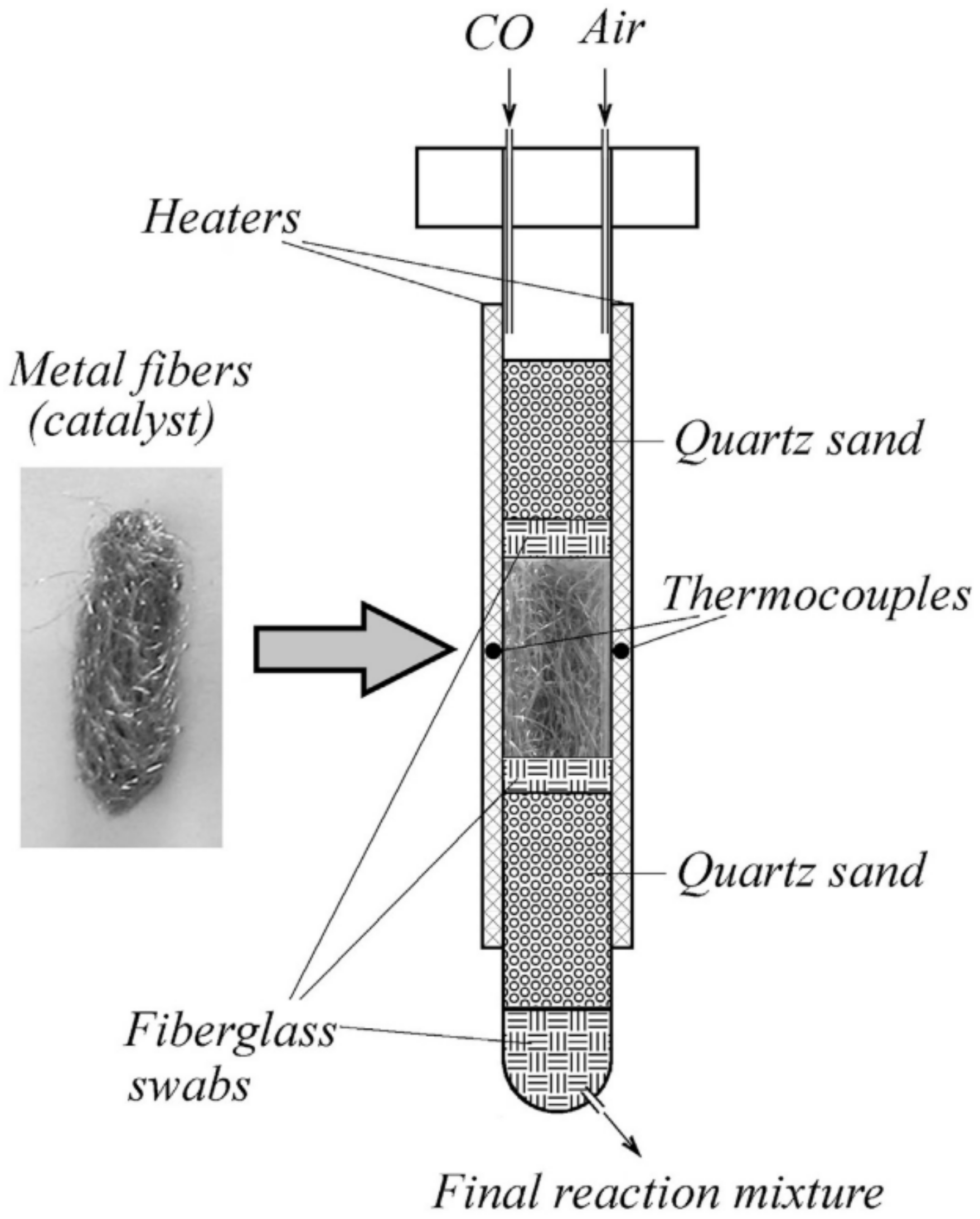
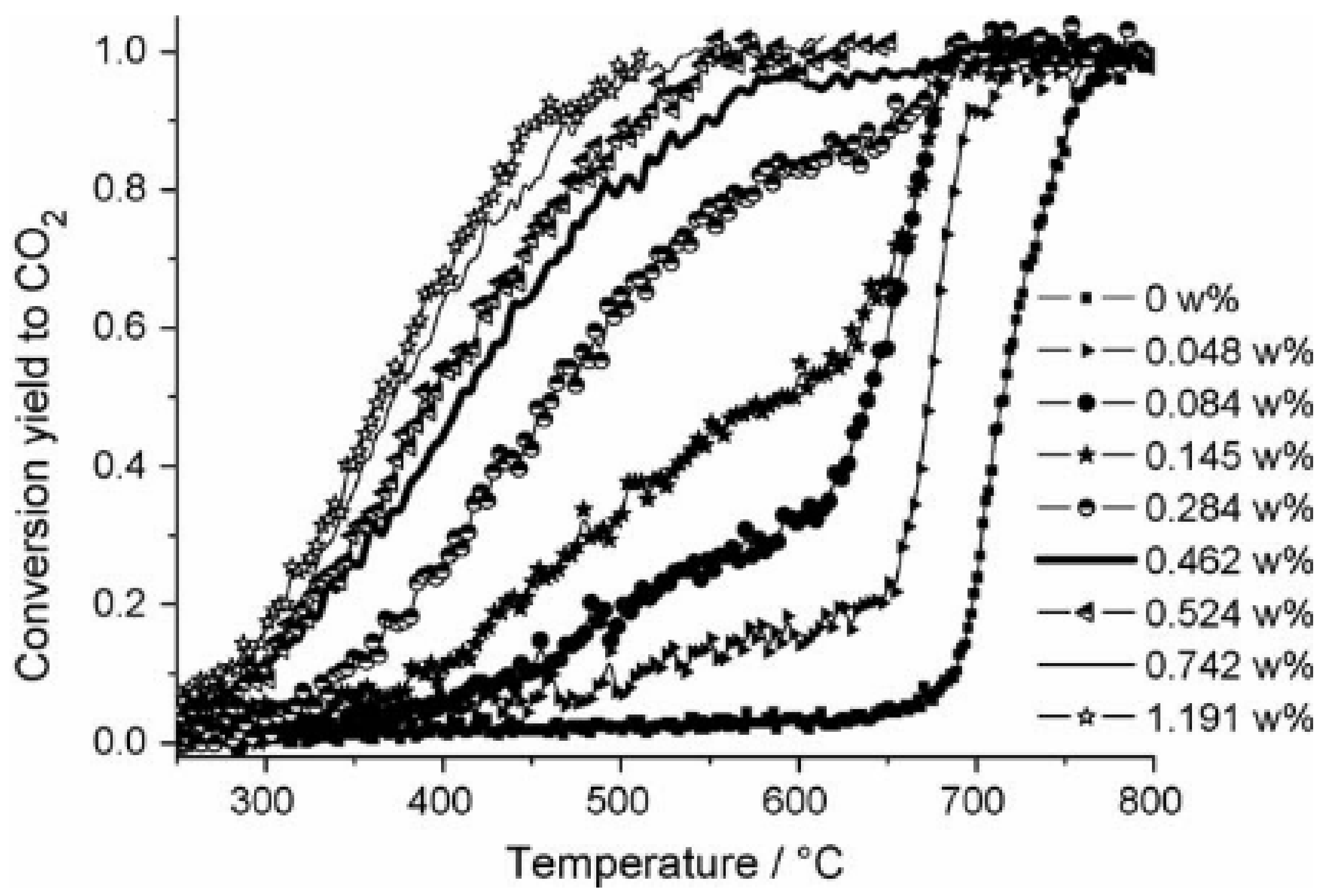
- Lukiyanchuk, I.V.; Vasilyeva, M.S.; Sergeev, A.A.; Nepomnyashchii, A.V.; Serov, M.M.; Krit, B.L. Role and behavior of ultra-thin gold films on the fiber materials surface in the CO oxidation process. J. Alloys Compd. 2021, 852, 157042. [Google Scholar] [CrossRef]
- Avila, P.; Montes, M.; Miró, E.E. Monolithic reactors for environmental applications: A review on preparation technologies. Chem. Eng. J. 2005, 109, 11–36. [Google Scholar] [CrossRef]
- Bahlawane, N.; Rivera, E.F.; Kohse-Höinghaus, K.; Brechling, A.; Kleineberg, U. Characterization and tests of planar Co3O4 model catalysts prepared by chemical vapor deposition. Appl. Catal. B Environ. 2004, 53, 245–255. [Google Scholar] [CrossRef]
- Moro-oka, Y.; Ozaki, A. Regularities in catalytic properties of metal oxides in propylene oxidation. J. Catal. 1966, 5, 116–124. [Google Scholar] [CrossRef]
- Busca, G.; Finocchio, E.; Ramis, G.; Ricchiardi, G. On the role of acidity in catalytic oxidation. Catal. Today 1996, 32, 133–143. [Google Scholar] [CrossRef]
- Stoian, M.; Lazar, L.; Uny, F.; Sanchette, F.; Fechete, I. Chemical vapour deposition (CVD) technique for abatement of volatile organic compounds (VOCs). Rev. Chim. 2020, 71, 97–113. [Google Scholar] [CrossRef]
- Jansson, J.; Skoglundh, M.; Fridell, E.; Thormählen, P. A mechanistic study of low temperature CO oxidation over cobalt oxide. Top. Catal. 2001, 16–17, 385–389. [Google Scholar] [CrossRef]
- Bahlawane, N. Kinetics of methane combustion over CVD-made cobalt oxide catalysts. Appl. Catal. B Environ. 2006, 67, 168–176. [Google Scholar] [CrossRef]
- Moro-oka, Y.; Ueda, W.; Lee, K.H. The role of bulk oxide ion in the catalytic oxidation reaction over metal oxide catalyst. J. Mol. Catal. A Chem. 2003, 199, 139–148. [Google Scholar] [CrossRef]
- Waqas, M.; El Kasmi, A.; Wang, Y.; Kouotou, P.M.; Tian, Z.Y. CVD synthesis of Cu-doped cobalt spinel thin film catalysts for kinetic study of propene oxidation. Colloids Surf. A Physicochem. Eng. Asp. 2018, 556, 195–200. [Google Scholar] [CrossRef]
- Kansal, A. Sources and reactivity of NMHCs and VOCs in the atmosphere: A review. J. Hazard. Mater. 2009, 166, 17–26. [Google Scholar] [CrossRef] [PubMed]
- Assebban, M.; Kasmi, A.E.L.; Harti, S.; Chafik, T. Intrinsic catalytic properties of extruded clay honeycomb monolith toward complete oxidation of air pollutants. J. Hazard. Mater. 2015, 300, 590–597. [Google Scholar] [CrossRef] [PubMed]
- Kouotou, P.M.; Tian, Z.Y. Cobalt-iron oxides made by CVD for low temperature catalytic application. Phys. Status Solidi Appl. Mater. Sci. 2015, 212, 1508–1513. [Google Scholar] [CrossRef]
- Tian, Z.Y.; Kouotou, P.M.; El Kasmi, A.; Ngamou, P.H.T.; Kohse-Höinghaus, K.; Vieker, H.; Beyer, A.; Gölzhäuser, A. Low-temperature deep oxidation of olefins and DME over cobalt ferrite. Proc. Combust. Inst. 2015, 35, 2207–2214. [Google Scholar] [CrossRef]
- Kouotou, P.M.; Vieker, H.; Tian, Z.Y.; Ngamou, P.T.; El Kasmi, A.; Beyer, A.; Gölzhäuser, A.; Kohse-Höinghaus, K. Structure-activity relation of spinel-type Co-Fe oxides for low-temperature CO oxidation. Catal. Sci. Technol. 2014, 4, 3359–3367. [Google Scholar] [CrossRef]
- Törncrona, A.; Skoglundh, M.; Thormählen, P.; Fridell, E.; Jobson, E. Low temperature catalytic activity of cobalt oxide and ceria promoted Pt and Pd: -influence of pretreatment and gas composition. Appl. Catal. B Environ. 1997, 14, 131–145. [Google Scholar] [CrossRef]
- Liu, H.; Cheung, P.; Iglesia, E. Zirconia-supported MoOx catalysts for the selective oxidation of dimethyl ether to formaldehyde: Structure, redox properties, and reaction pathways. J. Phys. Chem. B 2003, 107, 4118–4127. [Google Scholar] [CrossRef] [Green Version]
- Waqas, M.; El Kasmi, A.; Wu, L.N.; Arshad, M.F.; Qin, W.; Tian, Z.Y. Catalytic combustion of CO over Cu-doped iron oxides: CO2 effects on activity. Fuel 2021, 289, 119760. [Google Scholar] [CrossRef]
- Merino, N.A.; Barbero, B.P.; Eloy, P.; Cadús, L.E. La1-xCaxCoO3 perovskite-type oxides: Identification of the surface oxygen species by XPS. Appl. Surf. Sci. 2006, 253, 1489–1493. [Google Scholar] [CrossRef]
- Christensen, J.M.; Grunwaldt, J.D.; Jensen, A.D. Importance of the oxygen bond strength for catalytic activity in soot oxidation. Appl. Catal. B Environ. 2016, 188, 235–244. [Google Scholar] [CrossRef] [Green Version]
- Liu, Y.; Zhao, Y.; Yu, Y.; Ahmad, M.; Sun, H. Facile synthesis of single-crystal mesoporous CoNiO2 nanosheets assembled flowers as anode materials for lithium-ion batteries. Electrochim. Acta 2014, 132, 404–409. [Google Scholar] [CrossRef]
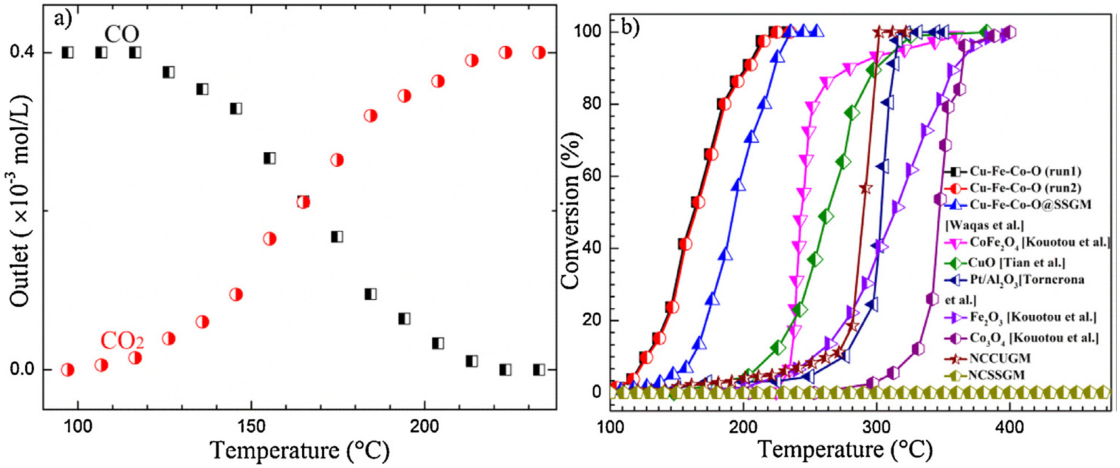
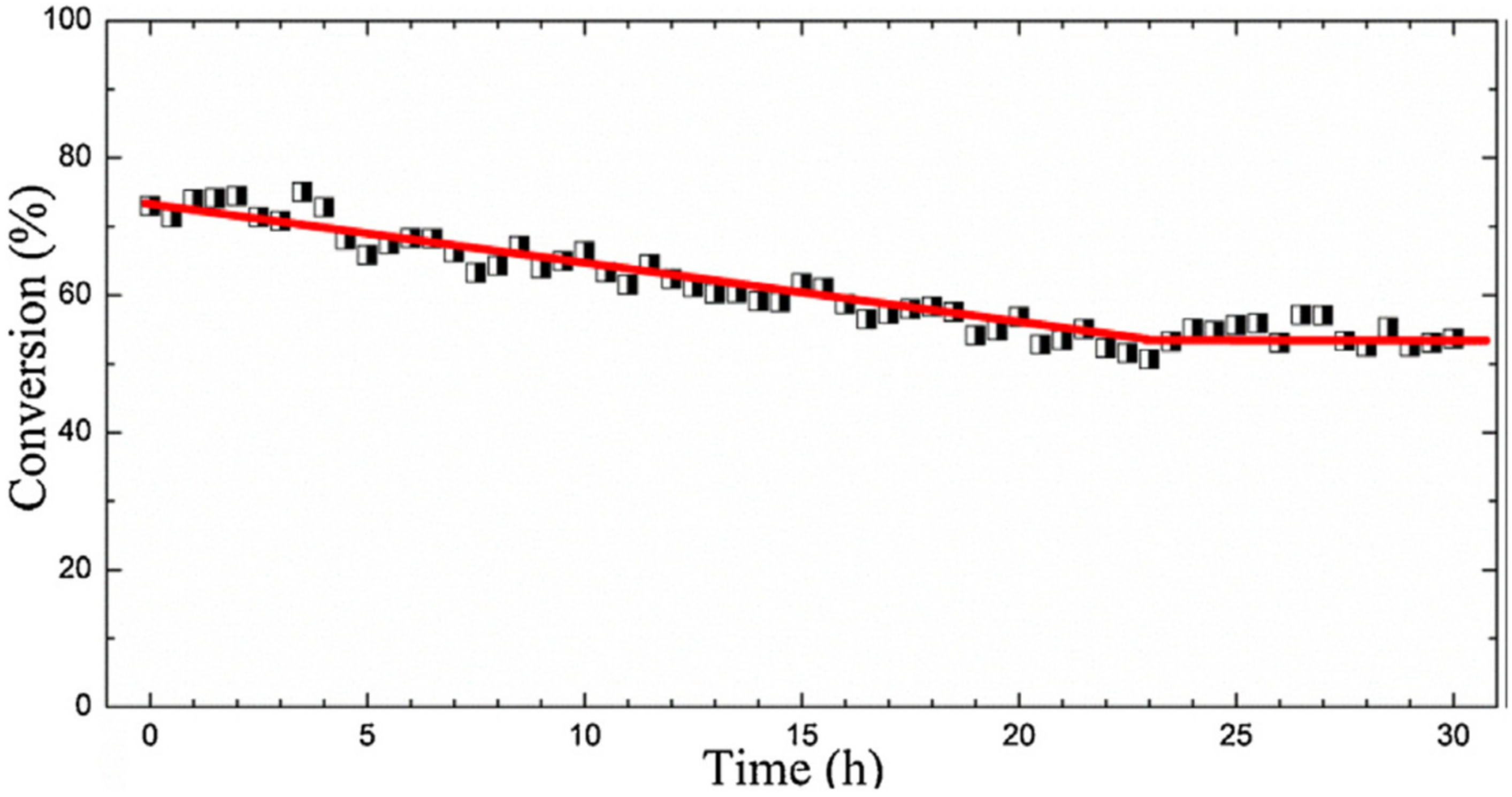
- Waqas, M.; Kouotou, P.M.; El Kasmi, A.; Wang, Y.; Tian, Z.Y. Role of copper grid mesh in the catalytic oxidation of CO over one-step synthesized Cu-Fe-Co ternary oxides thin film. Chin. Chem. Lett. 2020, 31, 1201–1206. [Google Scholar] [CrossRef]
- Kouotou, P.M.; Tian, Z.Y. Controlled synthesis of α-Fe2O3@Fe3O4 composite catalysts for exhaust gas purification. Proc. Combust. Inst. 2019, 37, 5445–5453. [Google Scholar] [CrossRef]
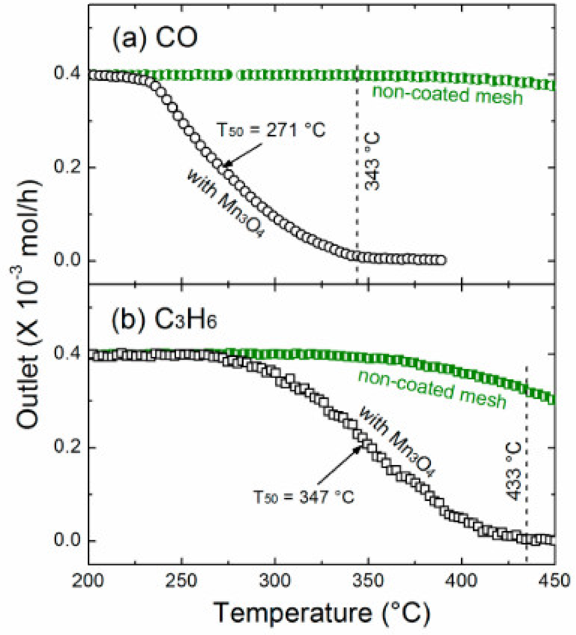
- Tian, Z.Y.; Kouotou, P.M.; Bahlawane, N.; Ngamou, P.T. Synthesis of the catalytically active Mn3O4 spinel and its thermal properties. J. Phys. Chem. C 2013, 117, 6218–6224. [Google Scholar] [CrossRef]


| Calcination Temperature | Dispersion (%) | ||
|---|---|---|---|
| PdO/Al2O3 | ZrO2-PdO/Al2O3 | ZrO2-Pd/Al2O3 | |
| 773 K | 32.9 | 10.6 | 18.5 |
| 973 K | 29.8 | 10.8 | |
| 1073 K | 24.2 | 13.2 | 18.6 |
| Catalyst | Preparation Technique | Active Phase | Test Conditions | Catalytic Performance | Reference |
|---|---|---|---|---|---|
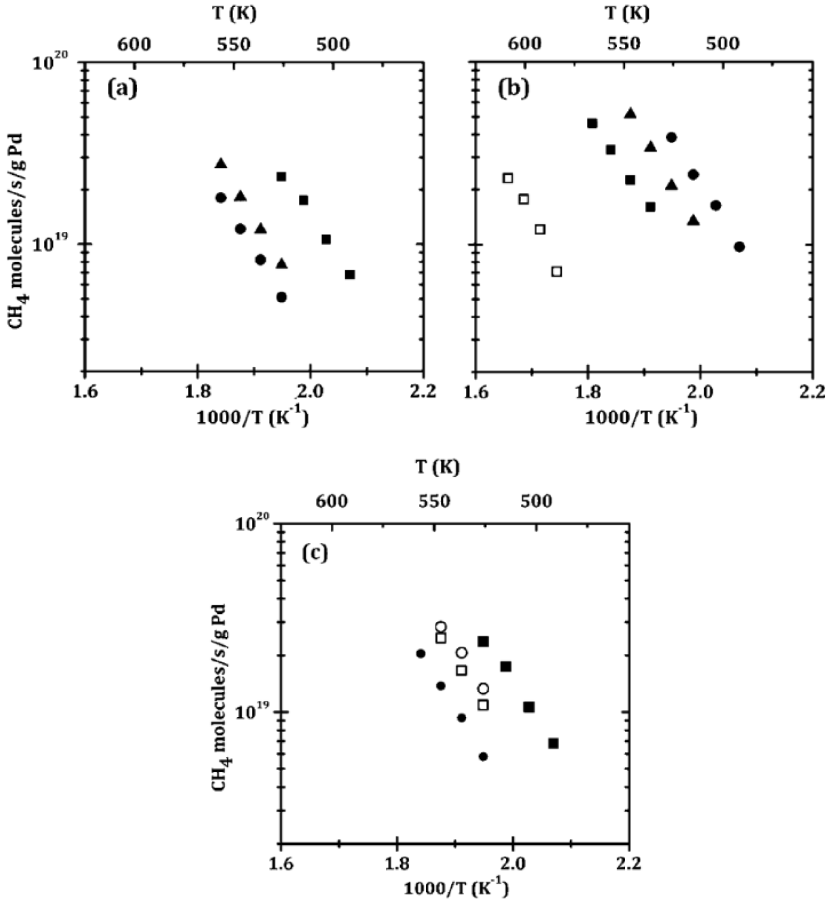
| ZrO2-Pd/Al2O3 | ALD | Pd | 0.5% CH4, 5% O2 in He (carrier gas); total flow rate 110 mL/min | Rate of 1019 CH4 molecules/(s g Pd) at 252 °C | [182] |
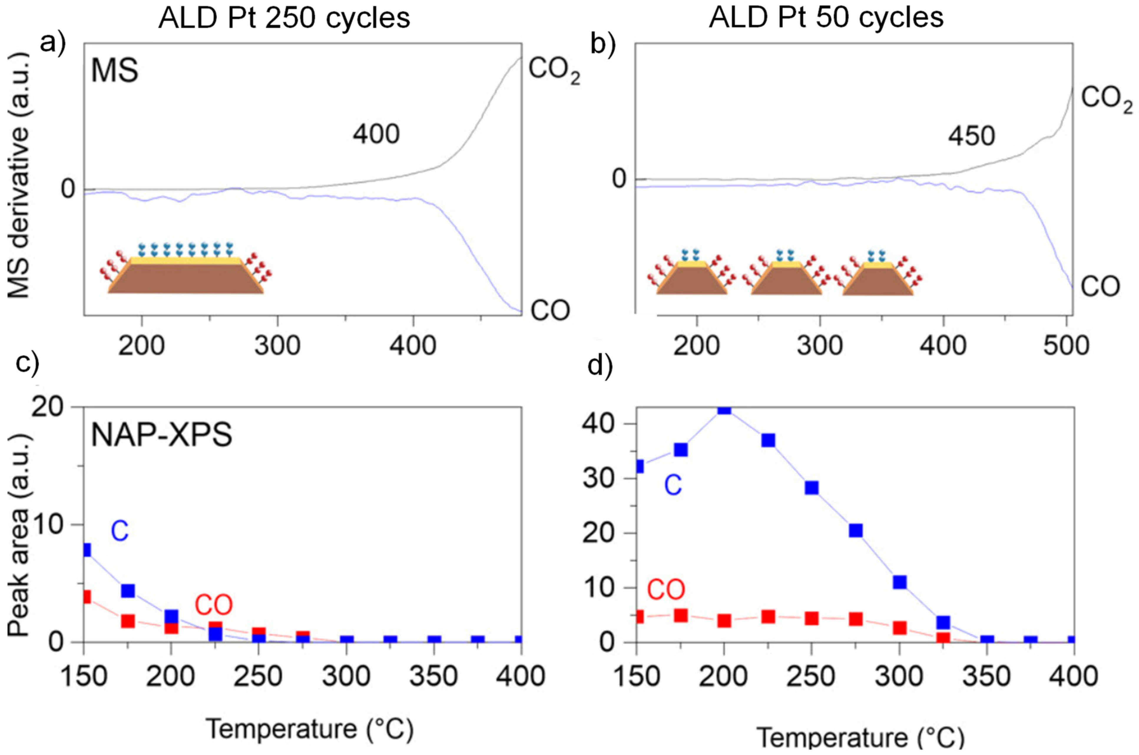
| Pt/ZrO2/Si | ALD | Pt | In NAP-XPS: 1 mbar CO, 2 mbar O2 | Onset temperature for CO oxidation: 400 °C | [183] |
| Pd/LaFeO3/MgAl2O4 | ALD | Pd | 0.5% CH4, 5% O2 in He (carrier gas); total flow rate 120 mL/min | Rate of 3 × 10¹⁷ CH4 molecules/(s⋅g cat) at 352 °C | [189] |
| Pt/LaFeO3/MgAl2O4 | ALD | Pt | 3.3% CO, 1.65% O2 in He (carrier gas); total flow rate 100 mL/min | T50: 150 °C | [190] |
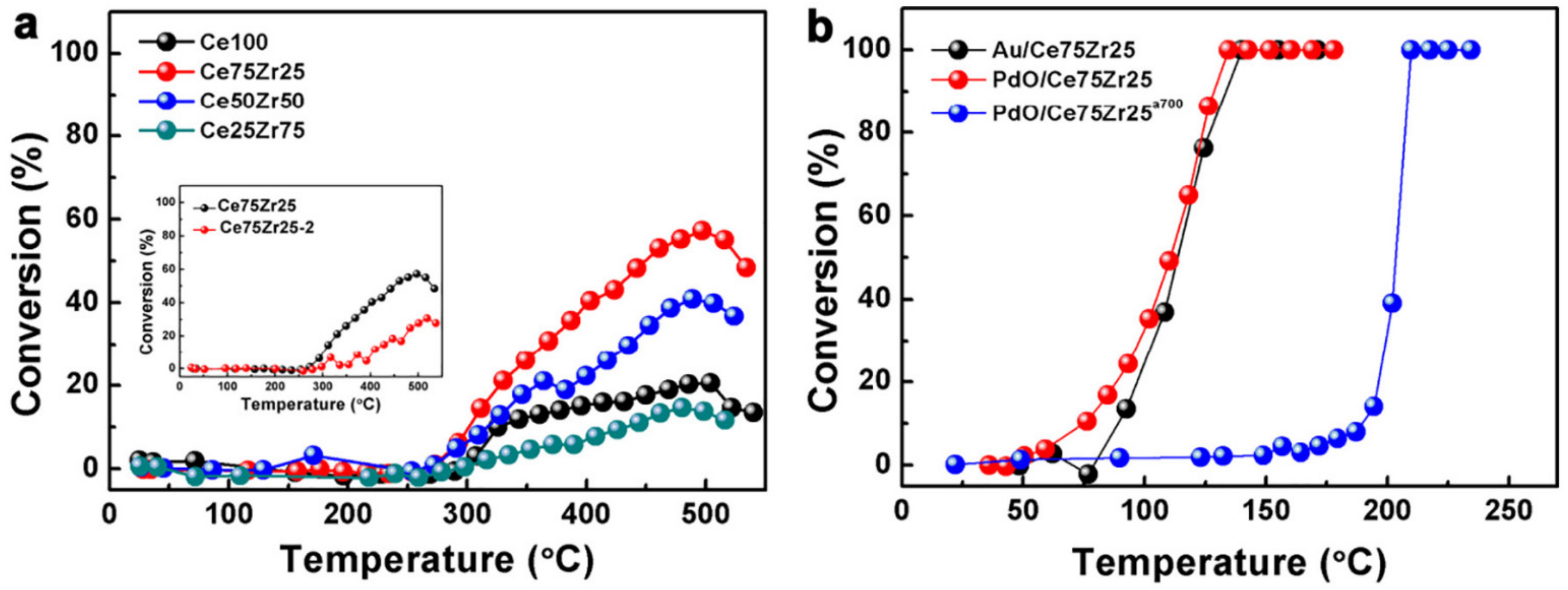
| Au/Ce75Zr25O2/Ti | PEO | Au | 1% CO, 20% O2 in He (carrier gas); total flow rate 10 mL/min | T50: 105 °C | [194] |
| PdO/Ce75Zr25O2/Ti | PEO | Pd | 1% CO, 20% O2 in He (carrier gas); total flow rate 10 mL/min | T50: 100 °C | [194] |
| Au/Ni-Cu-Fe-Mn | Electron beam evaporation | Au | 5% CO in air; total flow rate 50 mL/min | T50: 240 °C | [197] |
| Au/Ti | Electron beam evaporation | Au | 5% CO in air; total flow rate 50 mL/min | T50: 450 °C | [197] |
| Catalyst | Preparation Technique | Active Phase | Test Conditions | Catalytic Performance | Reference |
|---|---|---|---|---|---|
| Co3O4/steel | CVD | Co3O4 | 2% propane, 4.7% Ar in air; total flow rate: 107 mL/min | T50: 400 °C | [199] |
| Co3O4/steel | CVD | Co3O4 | 3.2% ethanol, 4.6% Ar in air; total flow rate: 109 mL/min | T50: 300 °C | [199] |
| Co3O4/cordierite | CVD | Co3O4 | 2% CH4, 20% O2 in Ar; total flow rate: 100 mL/min | T50: 350 °C | [204] |
| CoCuOx/SSGM | PSE-CVD | Co3O4 | 1% propene, 10% O2 in Ar; GHSV: 150,000 mL g−1 h−1 | T50: 311 °C | [206] |
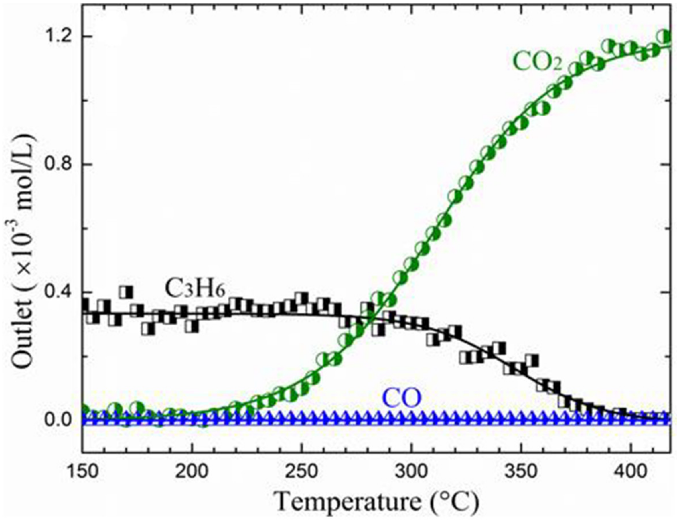
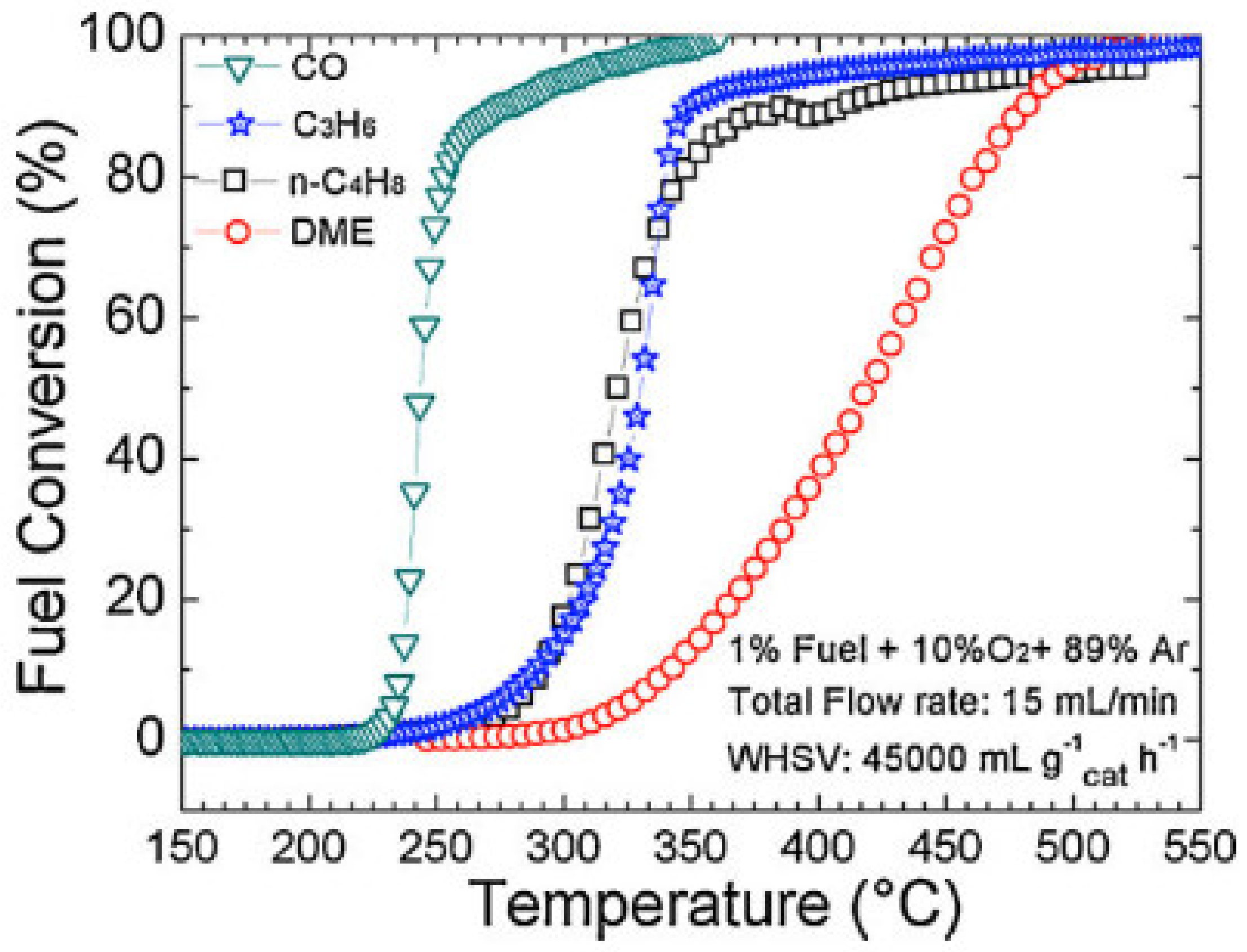
| CoFe2O4/SSGM | PSE-CVD | CoFeOx | 1% CO, 10% O2 in Ar; total flow rate: 15 mL/min; WHSV: 45,000 mL g−1 h−1 | T50: 243 °C | [209] |
| CoFe2O4/SSGM | PSE-CVD | CoFeOx | 1% propene, 10% O2 in Ar; total flow rate: 15 mL/min; WHSV: 45,000 mL g−1 h−1 | T50: 313 °C | [209] |
| FeCuO2/SSGM | PSE-CVD | FeCuOx | 1% CO, 20% O2 in Ar; total flow rate: 20 mL/min; WHSV: 184,500 mL g−1 h−1 | T50: 220 °C | [214] |
| CuFeCoOx/CUGM | PSE-CVD | CuFeCoOx | 1% CO, 20% O2 in Ar; WHSV: 75,000 mL g−1 h−1 | T50: 162 °C | [218] |
| Mn3O4/SSGM | PSE-CVD | Mn3O4 | 1% CO, 10% O2 in Ar; WHSV: 75,000 mL g−1 h−1 | T50: 271 °C | [220] |
| Mn3O4/SSGM | PSE-CVD | Mn3O4 | 1% propene, 10% O2 in Ar; GHSV: 75,000 mL g−1 h−1 | T50: 347 °C | [220] |
Publisher’s Note: MDPI stays neutral with regard to jurisdictional claims in published maps and institutional affiliations. |
© 2021 by the authors. Licensee MDPI, Basel, Switzerland. This article is an open access article distributed under the terms and conditions of the Creative Commons Attribution (CC BY) license (https://creativecommons.org/licenses/by/4.0/).
Share and Cite
Stoian, M.; Maurer, T.; Lamri, S.; Fechete, I. Techniques of Preparation of Thin Films: Catalytic Combustion. Catalysts 2021, 11, 1530. https://doi.org/10.3390/catal11121530
Stoian M, Maurer T, Lamri S, Fechete I. Techniques of Preparation of Thin Films: Catalytic Combustion. Catalysts. 2021; 11(12):1530. https://doi.org/10.3390/catal11121530
Chicago/Turabian StyleStoian, Marius, Thomas Maurer, Salim Lamri, and Ioana Fechete. 2021. "Techniques of Preparation of Thin Films: Catalytic Combustion" Catalysts 11, no. 12: 1530. https://doi.org/10.3390/catal11121530
APA StyleStoian, M., Maurer, T., Lamri, S., & Fechete, I. (2021). Techniques of Preparation of Thin Films: Catalytic Combustion. Catalysts, 11(12), 1530. https://doi.org/10.3390/catal11121530