Article

NiO-TiO2 p-n Heterojunction for Solar Hydrogen Generation

1
Research Institute of Petroleum Exploration and Development (RIPED), CNPC, Beijing 100083, China
2
Department of Chemical and Petroleum Engineering, University of Calgary, 2500 University Drive, NW, Calgary, AB T2N 1N4, Canada
*
Authors to whom correspondence should be addressed.
Catalysts 2021, 11(12), 1427; https://doi.org/10.3390/catal11121427
Submission received: 10 November 2021 / Revised: 21 November 2021 / Accepted: 23 November 2021 / Published: 24 November 2021

Abstract

:
Photocatalytic water splitting for hydrogen production has been widely recognized as a promising strategy for relieving the pressure from energy crisis and environmental pollution. However, current efficiency for photocatalytic hydrogen generation has been limited due to a low separation of photogenerated electrons and holes. p-n heterojunction with a built-in electric field emerges as an efficient strategy for photocatalyst design to boost hydrogen evolution activities due to a spontaneous charge separation. In this work, we investigated the effect of different preparation methods on photocatalytic hydrogen production over NiO-TiO2 composites. The results demonstrated that a uniform distribution of NiO on a surface of TiO2 with an intimate interfacial interaction was formed by a sol-gel method, while direct calcination tended to form aggregation of NiO, thus leading to an uneven p-n heterojunction structure within a photocatalyst. NiO-TiO2 composites fabricated by different methods showed enhanced hydrogen production (23.5 ± 1.2, 20.4 ± 1.0 and 8.8 ± 0.7 mmolh−1g−1 for S1-20%, S2-20% and S3-10%, respectively) as compared with pristine TiO2 (6.6 ± 0.7 mmolh−1g−1) and NiO (2.1 ± 0.2 mmolh−1g−1). The current work demonstrates a good example to improve photocatalytic hydrogen production by finely designing p-n heterojunction photocatalysts.

Graphical Abstract

1. Introduction

Over the past decades, environmental pollution and energy depletion have become increasingly critical. Photocatalysis has been realized as a potential strategy to solve these two global issues [1]. For a long time, environmental photocatalysis over semiconductors has been widely investigated for environmental remediation such as waste water treatment [2]. Since Fujishima and Honda firstly demonstrated the photoelectrolysis of water over crystalline TiO2, photocatalytic water splitting for hydrogen production and photocatalytic carbon dioxide valorization have also attracted great attention as the environmentally friendly solutions to further overcome energy and environmental crisis [3,4,5]. Solar-driven water splitting over transition metal oxides [6,7,8], composite oxides [9,10], carbonitride and chalcogenides [11,12] have been widely investigated, wherein n-type anatase TiO2 is the most commonly used photocatalyst due to its nontoxicity, high chemical stability, cost-effectiveness and facile structure modification [13,14]. However, its limited quantum efficiency because of the high recombination rate of electron-hole pairs and its intrinsic wide band gap still hinder its commercialization. Herein, numerous strategies have been applied to improve the photocatalytic activity of TiO2 materials, such as forming heterostructure with other semiconductors, doping, dye sensitization, and exposed facets modification [14,15]. Among them, heterostructures has been revealed to be an efficient method to improve photocatalytic efficiency [16,17,18,19]. As a typical heterostructure, p-n junction constructed by combining a n-type semiconductor (electron-rich) with a p-type semiconductor (hole-rich) can be a very efficient strategy to realize the separation of photogenerated electrons and holes. The charge separation is spontaneously driven by a formed built-in electric field and then the enhanced photocatalytic performance can be realized [20,21,22].
NiO is a typical p-type semiconductor and it has widely been combined with TiO2 to form the p-n heterojunction due to its suitable energy band structure, high charge carrier concentration, high chemical stability and low cost [23]. To date, many methods have already been developed to prepare NiO-TiO2 nanocomposites, such as hydrothermal, incipient wetness impregnation, sol-gel, and evaporation-induced methods [24,25,26,27]. Although an inner-built electric field is a very efficient manner to improve the transfer of charge carriers between TiO2 and NiO, the commonly fabricated nanocomposites usually suffer an untight contact between these two components, leading to a fast charge accumulation at a nanoparticle surface during the photocatalytic process. These accumulated charges become a recombination center to reduce the photocatalytic quantum efficiency. Herein, a rational design of these nanocomposites to avoid a contact gap between TiO2 and NiO or to rapidly transfer accumulated charges is the key factor to further improve a photocatalytic activity of such a p-n heterojunction system. Previous publications have introduced materials with excellent electrical conductivity onto a surface of TiO2 or NiO to realize a rapid charge transfer, such as graphene, metal Ni, and Au [28]. However, this combination always requires many complicated experimental procedures.
Herein, we designed and fabricated NiO-TiO2 nanocomposites to boost photocatalytic hydrogen production by using simple and facile methods to form a p-n heterojunction structure. Three strategies were investigated in this study to prepare a series of NiO-TiO2 photocatalysts with different NiO loading. A photocatalytic hydrogen production activity was revealed to be related to the NiO dispersion, loading and interaction with TiO2. As a result, NiO-TiO2 composites showed excellent performance for photocatalytic hydrogen production from water splitting as compared with pristine TiO2 and NiO. This work sheds light on improving solar-to-hydrogen conversion by finely designing p-n heterojunction photocatalysts.

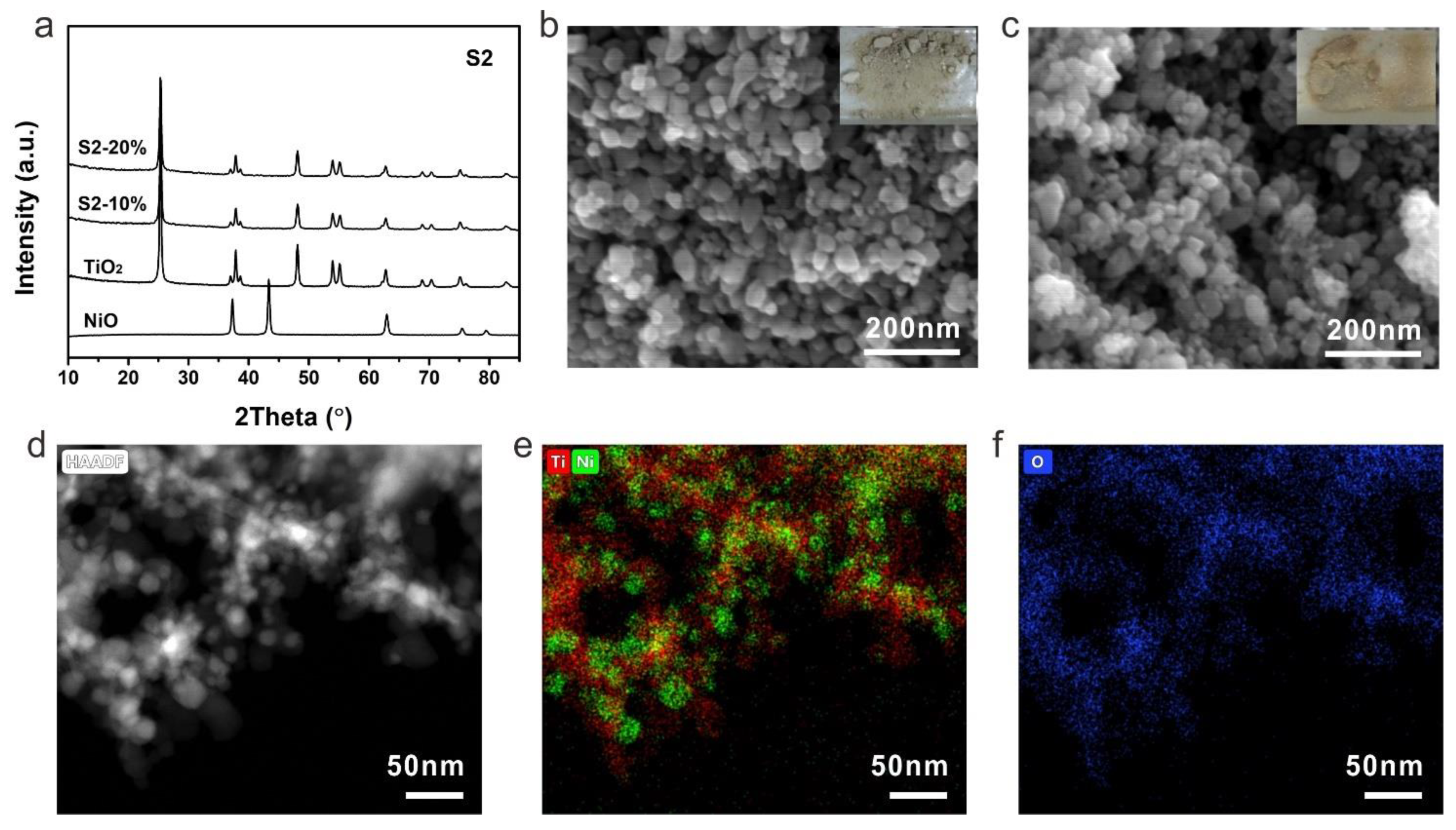
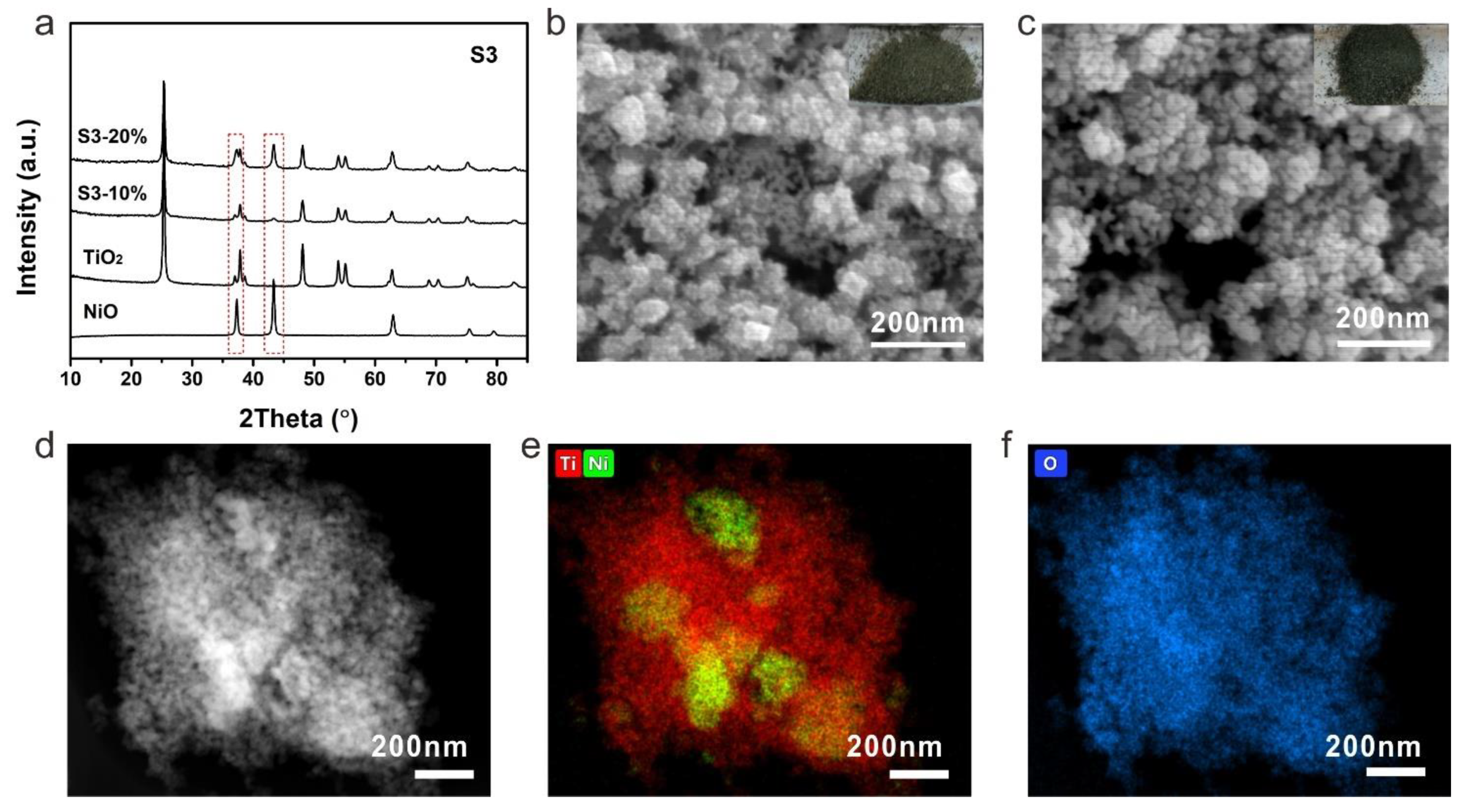
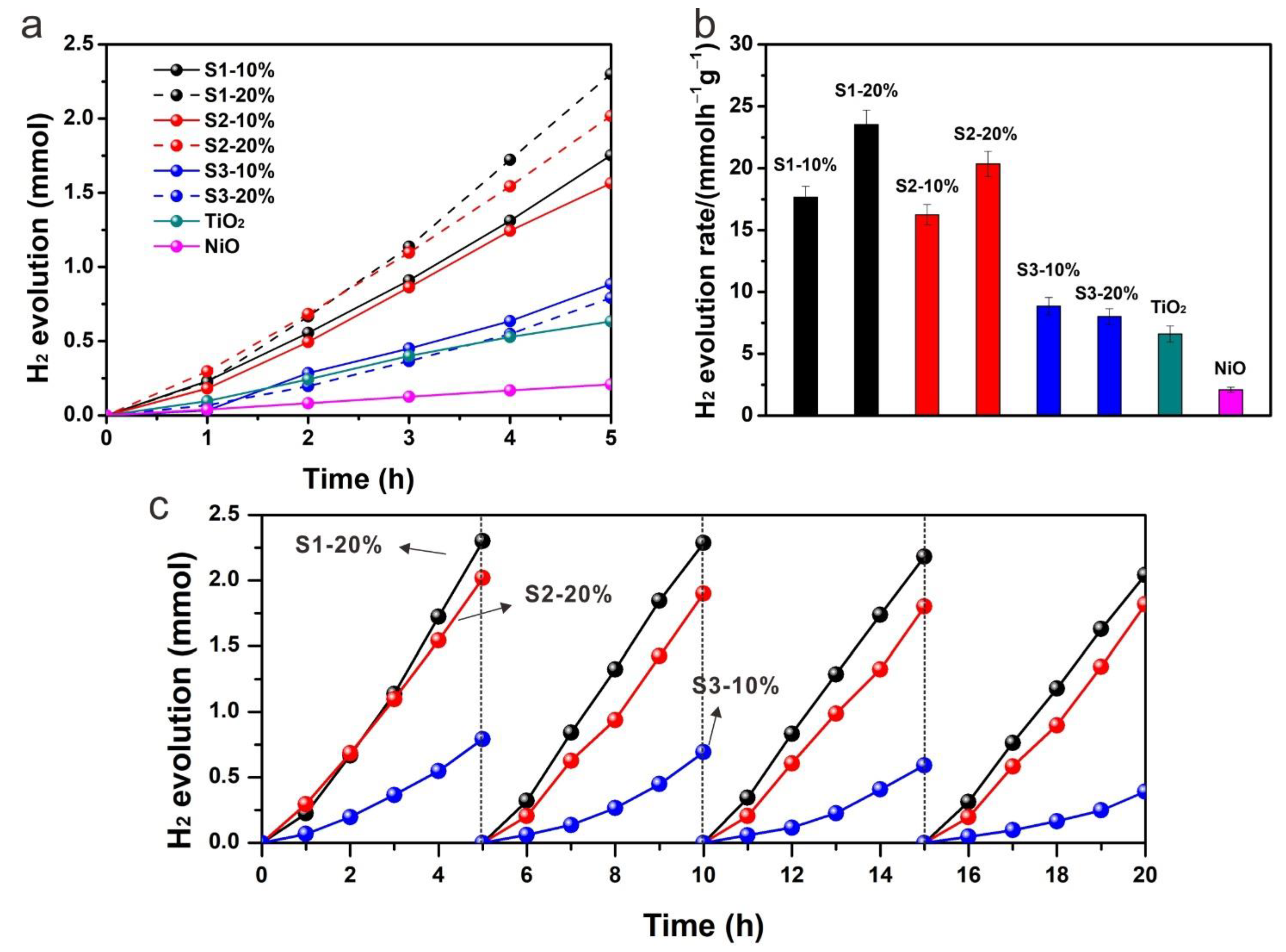
2. Results and Discussion

Figure 1 illustrates three fabrication processes for NiO-TiO2 nanoparticles. Strategy 1 (S1) shows a process by using both precursors of NiO and TiO2 (nickel acetate and tetraisopropyl titanate) directly. A nanocrystal of TiO2 covered by NiO clusters can be obtained during a sol-gel process and the following thermal treatment endows the nanocrystal with high crystallinity. This method can generate NiO-TiO2 nanocomposites with low NiO loading according to our previous work [29]. However, this method also leads to a crystal transformation of NiO to form NiTiO3, which has negative effects on photocatalytic hydrogen production [30]. To avoid the formation of NiTiO3, crystalline TiO2 was used to replace its precursor tetraisopropyl titanate in strategy 2 (S2). During a hydrothermal process, nickel ions are only absorbed on a surface of TiO2 rather than penetrated into TiO2 crystal as the high crystallinity of TiO2 inhibits a crystal transformation. NiO-TiO2 nanocomposites with a high dispersion of NiO can herein be obtained after calcination. However, the second strategy can only prepare NiO-TiO2 nanocomposites with a low NiO loading due to a weak electrostatic adsorption ability of a TiO2 surface. Herein, to further improve the loading of NiO, strategy 3 (S3) was employed by directly heating the suspension of TiO2 and nickel acetate followed by calcination. The effects of photocatalyst preparation strategies on NiO loading, a crystal size, a pore size/distribution, and photocatalytic hydrogen production were compared as shown in Table 1. It appears that the samples from S1 have almost the same parameters and performance as those from S2. Higher NiO content endows the samples from S1 and S2 with better photocatalytic hydrogen production. However, further increasing NiO content by S3 causes a decrease in hydrogen evolution.
The morphology of NiO-TiO2 composites prepared by strategy 1 was firstly investigated by scanning electron microscopy (SEM). Nanocrystals with a size of around 20 nm can be clearly observed for S1-10% (Figure 2a). Further increasing the loading of NiO, the size increased to around 30 nm for S2-20% (Figure 2b). The XRD patterns demonstrated that both S1-10% and S1-20% were mainly composed by anatase TiO2 with high crystallinity, indicating the presence of NiO with extremely low content in the as-fabricated composites (Figure 2c). The presence and distribution of NiO can be revealed by transmission electron microscopy (TEM). NiO nanocrystals with a size of around 30 nm were observed, with high crystallinity as evidenced by the distinguishable lattice fringe (Figure 3d). Numerous bright dots can be clearly observed on the surface of a TiO2 nanocrystal, which were ascribed to the loaded NiO, indicating that the presence of NiO was in the form of an ultrafine nanocluster and its distribution was uniform on the surface of TiO2. The even dispersion of NiO increases the photocatalytic performance due to the formation of numerous p-n heterojunction channels. However, the content of NiO by this method was limited to <3.33% as further increasing NiO loading would introduce the formation of NiTiO3 [29].
The samples prepared by strategy 2 were then investigated by XRD to firstly check their components. Similar to the samples from strategy 1, typical TiO2 with an anatase phase was detected and no peak of NiO was observed due to a low content of NiO (Figure 3a). Nanocrystals can be identified from SEM images for both S2-10% and S2-20% (Figure 3b,c). Because of the low content of NiO, the obtained photocatalysts exhibited a light grey color. As crystalline TiO2 was used to prepare the composites, NiTiO3 can be avoided even at a high concentration of a nickel precursor. The dispersion and interaction between TiO2 and NiO were then investigated by TEM. The high-angle annular dark-field scanning transmission electron microscopy (HAADF-STEM) showed a distinguishable nanocrystal of S2-20% (Figure 3d). The corresponding elemental mapping of Ti and Ni demonstrated a uniform distribution of NiO on TiO2, indicating the formation of uniform p-n heterojunction within the photocatalyst by strategy 2 (Figure 3e,f).
Due to the low content of NiO in S1 and S2, XRD did not show the typical peaks of NiO. To further demonstrate the chemical state of nickel in S1 and S2, X-ray photoelectron spectroscopy (XPS) was performed on samples S1-20% and S2-20%. The high-resolution XPS signal of Ni 2p was shown in Figure 4. It is clear that the Ni 2p spectrum of S1-20% has the same peak positions compared with that of S2-20%, indicating the chemical state of nickel in S1-20% and S2-20% is the same. Typical peaks at 855.5 eV and 873.1 eV corresponds to Ni 2p3/2 and Ni 2p1/2 respectively. The corresponding satellite peaks were also detected. The splitting energy of Ni 2p3/2 and Ni 2p1/2 is 17.6 eV, indicating the presence of nickel species is NiO rather than metallic nickel.
The samples prepared by strategy 3 were then investigated by XRD to check their components and crystallinity. Different from previous photocatalysts, the S3-10% and S3-20% showed typical diffusion peaks of NiO apart from the anatase TiO2 (Figure 5a). The intensities of NiO peaks were much higher of S3-20% than that of S3-10%, indicating a higher content of NiO in S3-20%. With high NiO loading, the color of NiO-TiO2 composites turned to black, which helps to improve the utilization of incident light. The morphology of S3-10% was quite different to that of the previous samples. A smooth surface of TiO2 nanocrystal changed to a rough surface due to the coverage of NiO on TiO2 and stick-like NiO can also be identified among the TiO2 nanocrystals (Figure 5b). The aggregation was more obvious with a higher NiO content (Figure 5c). Even though high NiO loading can be obtained by this method, the dispersion of NiO in the composite was revealed to be uneven. The NiO aggregation can clearly be observed by the HAADF-STEM and corresponding elemental mapping results (Figure 5d–f).
To compare the photocatalytic activities of different nanocomposites, hydrogen production in the presence of methanol as an electron donor was performed. Figure 6a shows the photocatalytic hydrogen production along with reaction time of pure NiO, pure TiO2 and other nanocomposites. All the samples exhibited almost a linear relationship of hydrogen production with reaction time. A small increase in hydrogen production rate could be observed at around 4 h and 5 h reaction, which is mainly due to the self-healing process, i.e., the in-situ reduction of oxidized Ni species to metallic Ni, as very recently demonstrated by operando XAS measurements [31]. The presence of metallic Ni is linked to improved photocatalytic performances. Pure NiO showed a low photocatalytic hydrogen production efficiency due to its p-type semiconductor property. In contrast, n-type TiO2 with electrons as charge carriers showed a relatively higher hydrogen generation rate (6.60 mmolh−1g−1). However, the performance of pure TiO2 was still limited due to a high recombination of photogenerated electrons and holes. Once TiO2 was combined with NiO, the photocatalytic performance was enhanced significantly (23.5 ± 1.2, 20.4 ± 1.0 and 8.8 ± 0.7 mmolh−1g−1 for S1-20%, S2-20% and S3-10%, respectively). Sample S1-20% exhibited the highest photocatalytic hydrogen activity and S2-20% showed a similar hydrogen production efficiency (Figure 6b). However, the samples from strategy 3 showed a much reduced photocatalytic performance, indicating a significant effect of a preparation method on the charge separation efficiency. It has been recognized that a more uniform distribution of NiO on a surface of TiO2 introduces more p-n heterojunction channels for the charge separation, thus leading to a higher photocatalytic performance. Even although the contents of NiO in the composites from strategy 1 and 2 were much lower than those from strategy 3, the enhanced photocatalytic performance revealed the dominant role of p-n heterojunction in improving photocatalytic hydrogen production. S3-10% showed a little higher hydrogen evolution rate than that of S3-20%, which was probably due to the limited light absorption by TiO2 in S3-20% as a high content of NiO with black color competes in light absorption. Cycling tests were performed for each photocatalyst to check its photocatalytic stability. S1-20% and S2-20% exhibited excellent stability during the cycling tests while S3-10% showed an obvious decrease in hydrogen production activity, indicating that high dispersion of NiO stabilizes the composite.
The mechanism of photocatalytic hydrogen production over the as-prepared p-n heterojunction was proposed accordingly (Figure 7). Due to the different Femi levels of NiO and TiO2, the built-in electric field spontaneously drives the spatial separation of photogenerated charges, leading to the band bending at the interface. Under the irradiation of simulated solar light, both NiO and TiO2 are activated to produce electrons and holes. Due to the relative positions of conduction band (CB) and valence band (VB), the photo-activated electrons on the CB of NiO are transferred to the CB of TiO2 and hydrogen is produced at the CB of TiO2 by proton or water reduction reaction. While the photogenerated holes at the VB of TiO2 are transferred to the VB of NiO and then consumed by sacrificial agent methanol. The uniform distribution of NiO leads to efficient formation of p-n heterojunction, thus improve charge separation for photocatalytic hydrogen production. The as-fabricated p-n heterojunction nanocomposites shed new light on the high solar-to-chemical conversion efficiency in a noble-metal free photocatalytic system.

3. Experimental Section

3.1. Materials

All the reagents in the experiments are in analytic grade and are commercially available. Tetraisopropyl titanate (Ti(OC4H9)4), nickel acetate tetrahydrate (Ni(CH3COO)2·4H2O), ethanol and acetic acid (CH3COOH) were purchased from Aldrich Industrial Co., Ltd. (Wuxi, China) without any further purification.

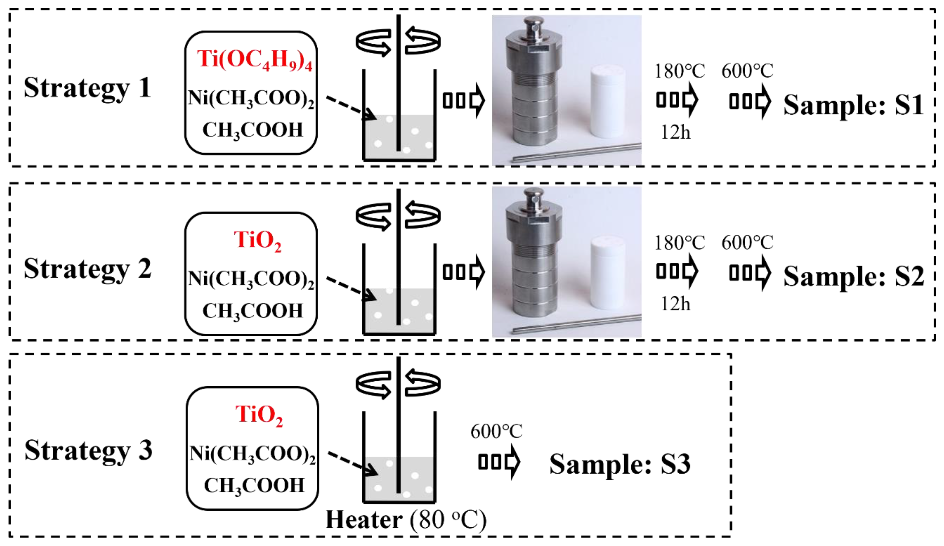
3.2. Synthesis of NiO-TiO2 Photocatalysts

3.2.1. Strategy 1

Ni(CH3COO)2·4H2O was firstly dissolved in 60 mL acetic acid and 2 mL Ti(OC4H9)4 was added dropwise into the mixture with vigorous stirring. After constantly stirred for 0.5 h, the mixture was transferred into a Teflon-lined autoclave for a hydrothermal treatment at 180 °C for 12 h. After cooling down, the precipitates were collected by centrifugation followed with washing with ethanol three times. The NiO-TiO2 samples were finally obtained after calcined at 600 °C for 2 h. NiO-TiO2 nanocomposites with different Ni:Ti ratios: 0.1 and 0.2 were fabricated by changing the amount of the added Ni(CH3COO)2·4H2O and labelled as S1-10% and S1-20%, respectively. Pure TiO2 and NiO as the reference samples were also fabricated in the same procedure without adding Ni(CH3COO)2·4H2O and Ti(OC4H9)4 respectively. The obtained pure TiO2 and NiO from hydrothermal treatment were directly used without calcination process.

3.2.2. Strategy 2

Ni(CH3COO)2·4H2O was firstly dissolved in 60 mL acetic acid. Then 0.2 g TiO2 fabricated above was added into the mixture with vigorous stirring. After constantly stirred for 0.5 h, the mixture was transferred into a Teflon-lined autoclave for a hydrothermal treatment at 180 °C for 12 h. The precipitates were collected by centrifugation followed with washing with ethanol three times. The final NiO-TiO2 samples were obtained after calcined at 600 °C for 2 h and the theoretical contents of 10% and 20% of Ni in mole were labelled as S2-10% and S2-20%, respectively.

3.2.3. Strategy 3

Ni(CH3COO)2·4H2O was first dissolved in 60 mL acetic acid with vigorous stirring. Then 0.2 g TiO2 fabricated above was added into the mixture. The suspension was constantly stirred on a heater until solid was obtained. The solid was calcined at 600 °C for 2 h and the theoretical contents of 10% and 20% of Ni in mole were labelled as S3-10% and S3-20%, respectively.

3.3. Characterization

Power X-ray diffraction (XRD, D8 ADVANCE, Berlin, Germany) at 40 kV, 40 mA equipped with a Cu anode X-ray tube (Cu Kα X-rays, λ = 1.54056 Å) was used to determine the crystalline phase of each sample. A field-emission scanning electron microscope (SEM, Hitachi S-4800, Tokyo, Japan) was performed to observe the sample morphology at a voltage of 5 kV and a transmission electron microscope (TEM, FEI Talos, USA) with an acceleration voltage of 200 kV. A micromeritic surface area and porosity analyzer (Micrometrics Tri Star II 3020, Ottawa, ON, Canada) was used to measure the specific surface area and pore distribution. The actual content of Ni in NiO-TiO2 composites was measured by an inductively coupled plasma emission spectrometer (ICP-AES, PerkinElmer Optima 4300DV, Waltham, MA, USA).

3.4. Photocatalytic H2 Evolution

The photocatalytic reactions were carried out in a closed circulation system (Labsolar-6A, Beijing Perfectlight Technology Co., Ltd., Beijing, China) using a PLS-SXE-300C lamp. A 20 mg sample was immersed in a mixed solution containing 50 mL water and 50 mL methanol. The suspension was sealed in a quartz reactor and after degassing, the reaction was undergoing under irradiation of UV-vis light (320–780 nm). The gas products were collected and analyzed periodically by a gas chromatograph (GC, Agilent 7890B, Santa Clara, CA, USA) with a thermal conductivity detector (TCD).

4. Conclusions

In summary, three strategies were used to fabricate a NiO-TiO2 p-n heterojunction photocatalyst. The results showed that a uniform distribution of NiO on a surface of TiO2 with intimate interfacial interaction was formed by the sol-gel and hydrothermal methods, while the direct calcination tended to form aggregation of NiO, thus leading to an uneven p-n heterojunction structure within the photocatalyst. Compared with pristine TiO2 (6.6 ± 0.7 mmolh−1g−1) and NiO (2.1 ± 0.2 mmolh−1g−1), the highest hydrogen production was achieved on S1-20% (23.5 ± 1.2 mmolh−1g−1). Besides, the high dispersion of NiO can also stabilize the photocatalyst for hydrogen production. This present work provides a simple and efficient method to greatly improve the solar-to-chemical energy conversion efficiency in a noble-metal free system by finely designing a p-n heterojunction structure.

Author Contributions

D.Z. and H.Z. designed and performed the experiment. S.W. contributed to the data analysis and characterizations. D.Z. drafted the original version. H.Z., J.H. and Z.C. reviewed and revised the manuscript. Z.C. supervised this project and provided funding. All authors have read and agreed to the published version of the manuscript.

Funding

This work is financially supported by the program, Key Technologies for Hydrogen Production by Renewable Energy (Wind, Solar and Hydro), PetroChina Research Institute of Petroleum Exploration and Development (RIPED) (YJG2019-14).

Data Availability Statement

Data is contained within the article.

Conflicts of Interest

The authors declare no conflict of interest.

References

  1. Schneider, J.; Matsuoka, M.; Takeuchi, M.; Zhang, J.L.; Horiuchi, Y.; Anpo, M.; Bahnemann, D.W. Understanding TiO2 photocatalysis: Mechanisms and materials. Chem. Rev. 2014, 114, 9919–9986. [Google Scholar] [CrossRef] [PubMed]
  2. Kubacka, A.; Fernandez-Garcia, M.; Colon, G. Advanced nanoarchitectures for solar photocatalytic applications. Chem. Rev. 2012, 112, 1555–1614. [Google Scholar] [CrossRef] [PubMed]
  3. Fujishima, A.; Honda, K. Electrochemical photolysis of water at a semiconductor electrode. Nature 1972, 238, 37–38. [Google Scholar] [CrossRef]
  4. Kudo, A.; Miseki, Y. Heterogeneous photocatalyst materials for water splitting. Chem. Soc. Rev. 2009, 38, 253–278. [Google Scholar] [CrossRef]
  5. Maeda, K.; Domen, K. Photocatalytic water splitting: Recent progress and future challenges. J. Phys. Chem. Lett. 2010, 1, 2655–2661. [Google Scholar] [CrossRef]
  6. Dinh, C.T.; Yen, H.; Kleitz, F.; Do, T.O. Three-dimensional ordered assembly of thin-shell Au/TiO2 hollow nanospheres for enhanced visible-light-driven photocatalysis. Angew. Chem. Int. Ed. 2014, 53, 6618–6623. [Google Scholar] [CrossRef]
  7. Zhang, L.J.; Li, S.; Liu, B.K.; Wang, D.; Xie, T.F. Highly efficient CdS/WO3 photocatalysts: Z-scheme photocatalytic mechanism for their enhanced photocatalytic H2 evolution under visible light. ACS Catal. 2014, 4, 3724–3729. [Google Scholar] [CrossRef]
  8. Wang, G.M.; Yang, X.Y.; Qian, F.; Zhang, J.Z.; Li, Y. Double-sided CdS and CdSe quantum dot co-sensitized ZnO nanowire arrays for photoelectrochemical hydrogen generation. Nano Lett. 2010, 10, 1088–1092. [Google Scholar] [CrossRef]
  9. Sun, S.M.; Wang, W.Z.; Li, D.Z.; Zhang, L.; Jiang, D. Solar light driven pure water splitting on quantum sized BiVO4 without any cocatalyst. ACS Catal. 2014, 4, 3498–3503. [Google Scholar] [CrossRef]
  10. Kato, H.; Asakura, K.; Kudo, A. Highly efficient water splitting into H2 and O2 over lanthanum-doped NaTaO3 photocatalysts with high crystallinity and surface nanostructure. J. Am. Chem. Soc. 2003, 125, 3082–3089. [Google Scholar] [CrossRef]
  11. Sathish, A.; Viswanath, R.P. Photocatalytic generation of hydrogen over mesoporous CdS nanoparticle: Effect of particle size, noble metal and support. Catal. Today 2007, 129, 421–427. [Google Scholar] [CrossRef]
  12. Holmes, M.A.; Townsend, T.K.; Osterloh, F.E. Quantum confinement controlled photocatalytic water splitting by suspended CdSe nanocrystals. Chem. Commun. 2012, 48, 371–373. [Google Scholar] [CrossRef] [PubMed] [Green Version]
  13. Guo, Q.; Zhou, C.; Ma, Z.; Ren, Z.; Fan, H.; Yang, X. Elementary photocatalytic chemistry on TiO2 surfaces. Chem. Soc. Rev. 2016, 45, 3701–3730. [Google Scholar] [CrossRef] [Green Version]
  14. Ge, M.Z.; Cao, C.Y.; Huang, J.Y.; Li, S.H.; Chen, Z.; Zhang, K.Q.; Al-Deyab, S.S.; Lai, Y.K. A review of one-dimensional TiO2 nanostructured materials for environmental and energy applications. J. Mater. Chem. A 2016, 4, 6772–6801. [Google Scholar] [CrossRef]
  15. Park, H.; Kim, H.I.; Moon, G.H.; Choi, W. Photoinduced charge transfer processes in solar photocatalysis based on modified TiO2. Energy Environ. Sci. 2016, 9, 411–433. [Google Scholar] [CrossRef] [Green Version]
  16. Moniz, S.J.A.; Shevlin, S.A.; Martin, D.J.; Guo, Z.X.; Tang, J.W. Visible-light driven heterojunction photocatalysts for water splitting—A critical review. Energy Environ. Sci. 2015, 8, 731–759. [Google Scholar] [CrossRef]
  17. Zhao, H.; Yu, X.; Li, C.-F.; Yu, W.; Wang, A.; Hu, Z.-Y.; Larter, S.; Li, Y.; Golam Kibria, M.; Hu, J. Carbon quantum dots modified TiO2 composites for hydrogen production and selective glucose photoreforming. J. Energy Chem. 2022, 64, 201–208. [Google Scholar] [CrossRef]
  18. Zhao, H.; Liu, P.; Wu, X.; Wang, A.; Zheng, D.; Wang, S.; Chen, Z.; Larter, S.; Li, Y.; Su, B.-L.; et al. Plasmon enhanced glucose photoreforming for arabinose and gas fuel co-production over 3DOM TiO2-Au. Appl. Catal. B Environ. 2021, 291, 120055. [Google Scholar] [CrossRef]
  19. Zhao, H.; Li, C.F.; Hu, Z.Y.; Liu, J.; Li, Y.; Hu, J.; Van Tendeloo, G.; Chen, L.H.; Su, B.L. Size effect of bifunctional gold in hierarchical titanium oxide-gold-cadmium sulfide with slow photon effect for unprecedented visible-light hydrogen production. J. Colloid Interface Sci. 2021, 604, 131–140. [Google Scholar] [CrossRef]
  20. Yu, X.; Zhang, J.; Zhao, Z.H.; Guo, W.B.; Qiu, J.C.; Mou, X.N.; Li, A.X.; Claverie, J.P.; Liu, H. NiO-TiO2 p-n heterostructured nanocables bridged by zero-bandgap rGO for highly efficient photocatalytic water splitting. Nano Energy 2015, 16, 207–217. [Google Scholar] [CrossRef]
  21. Rawool, S.A.; Pai, M.R.; Banerjee, A.M.; Arya, A.; Ningthoujam, R.S.; Tewari, R.; Rao, R.; Chalke, B.; Ayyub, P.; Tripathi, A.K.; et al. pn heterojunctions in NiO:TiO2 composites with type-II band alignment assisting sunlight driven photocatalytic H2 generation. Appl. Catal. B Environ. 2018, 221, 443–458. [Google Scholar] [CrossRef]
  22. Ren, X.; Gao, P.; Kong, X.; Jiang, R.; Yang, P.; Chen, Y.; Chi, Q.; Li, B. NiO/Ni/TiO2 nanocables with Schottky/p-n heterojunctions and the improved photocatalytic performance in water splitting under visible light. J. Colloid Interface Sci. 2018, 530, 1–8. [Google Scholar] [CrossRef] [PubMed]
  23. Lin, Z.Y.; Du, C.; Yan, B.; Wang, C.X.; Yang, G.W. Two-dimensional amorphous NiO as a plasmonic photocatalyst for solar H2 evolution. Nat. Commun. 2018, 9, 4036. [Google Scholar] [CrossRef] [PubMed] [Green Version]
  24. Uddin, M.T.; Nicolas, Y.; Olivier, C.; Jaegermann, W.; Rockstroh, N.; Junge, H.; Toupance, T. Band alignment investigations of heterostructure NiO/TiO2 nanomaterials used as efficient heterojunction earth-abundant metal oxide photocatalysts for hydrogen production. Phys. Chem. Chem. Phys. 2017, 19, 19279–19288. [Google Scholar] [CrossRef]
  25. Kamegawa, T.; Kim, T.H.; Morishima, J.; Matsuoka, M.; Anpo, M. Preferential oxidation of CO impurities in the presence of H2 on NiO-loaded and unloaded TiO2 photocatalysts at 293 K. Catal. Lett. 2009, 129, 7–11. [Google Scholar] [CrossRef]
  26. Chen, S.F.; Zhang, S.J.; Liu, W.; Zhao, W. Preparation and activity evaluation of p-n junction photocatalyst NiO/TiO2. J. Hazard. Mater. 2008, 155, 320–326. [Google Scholar]
  27. Chockalingam, K.; Ganapathy, A.; Paramasivan, G.; Govindasamy, M.; Viswanathan, A. NiO/TiO2 nanoparticles for photocatalytic disinfection of bacteria under visible light. J. Am. Ceram. Soc. 2011, 94, 2499–2505. [Google Scholar] [CrossRef]
  28. Oros-Ruiz, S.; Zanella, R.; Collins, S.E.; Hernandez-Gordillo, A.; Gomez, R. Photocatalytic hydrogen production by Au-MxOy (M=Ag, Cu, Ni) catalysts supported on TiO2. Catal. Commun. 2014, 47, 1–6. [Google Scholar] [CrossRef]
  29. Zhao, H.; Li, C.F.; Liu, L.Y.; Palma, B.; Hu, Z.Y.; Renneckar, S.; Larter, S.; Li, Y.; Kibria, M.G.; Hu, J.; et al. n-p Heterojunction of TiO2-NiO core-shell structure for efficient hydrogen generation and lignin photoreforming. J. Colloid Interface Sci. 2021, 585, 694–704. [Google Scholar] [CrossRef] [PubMed]
  30. Li, M.-W.; Yuan, J.-P.; Gao, X.-M.; Liang, E.-Q.; Wang, C.-Y. Structure and optical absorption properties of NiTiO3 nanocrystallites. Appl. Phys. A 2016, 122, 725. [Google Scholar] [CrossRef]
  31. Spanu, D.; Minguzzi, A.; Recchia, S.; Shahvardanfard, F.; Tomanec, O.; Zboril, R.; Schmuki, P.; Ghigna, P.; Altomare, M. An operando X-ray absorption spectroscopy study of a NiCu-TiO2 phtoocatalyst for H2 evolution. ACS Catal. 2020, 10, 8293–8302. [Google Scholar] [CrossRef]
Figure 1. Schematic illustration of three different fabrication processes for NiO-TiO2 nanoparticles.
Catalysts 11 01427 g001
Figure 2. SEM images of (a) S1-10% and (b) S1-20%, (c) XRD patterns and (d) HR-TEM image of S1-20%.
Catalysts 11 01427 g002
Figure 3. (a) XRD patterns, SEM images of (b) S2-10%, (c) S2-20%, (d) HAADF-STEM image of S2-20% and the corresponding elemental mapping (e) Ti (red), Ni (green) and (f) O (blue). Insets are the corresponding photographs of S2-10% and S2-20%.
Catalysts 11 01427 g003
Figure 4. High-resolution XPS signal of Ni 2p of (a) S1-20% and (b) S2-20%.
Catalysts 11 01427 g004
Figure 5. (a) XRD patterns, SEM images of (b) S3-10%, (c) S3-20%, (d) HAADF-STEM image of S3-20% and the corresponding elemental mapping (e) Ti (red), Ni (green) and (f) O (blue). Insets are the corresponding photographs of S3-10% and S3-20%.
Catalysts 11 01427 g005
Figure 6. (a) Hydrogen evolution along with reaction time, (b) the corresponding hydrogen generation rates of pure NiO, pure TiO2 and other nanocomposites, and (c) cycling tests of S1-20%, S2-20% and S3-10%.
Catalysts 11 01427 g006
Figure 7. Photocatalytic mechanism of NiO-TiO2 p-n heterojunction.
Catalysts 11 01427 g007
Table 1. Structural parameters along with photocatalytic hydrogen evolution of each sample.
SampleNiO Content (wt%)Crystallite Size XRD (nm)Crystallite Size SEM (nm)SBET/m2g−1Pore Size (nm)H2 Evolution rate/mmolh−1g−1
NiO-5540–809.5N/A2.1 ± 0.2
TiO2-2520–3031.95–506.6 ± 0.7
S1-10%1.72020–4038.05–5017.7 ± 0.9
S1-20%3.33020–4039.55–5023.5 ± 1.2
S2-10%1.53525–4536.45–4016.3 ± 0.8
S2-20%3.13525–4535.65–4020.4 ± 1.0
S3-10%9.84030–5050.75–408.9 ± 0.7
S3-20%19.44530–5052.75–408.8 ± 0.7
Publisher’s Note: MDPI stays neutral with regard to jurisdictional claims in published maps and institutional affiliations.

