Article

Influence of NiO/La2O3 Catalyst Preparation Method on Its Reactivity in the Oxy-Steam Reforming of LNG Process

by
Magdalena Mosinska
*,
Waldemar Maniukiewicz
,
Malgorzata I. Szynkowska-Jozwik
and
Pawel Mierczynski
*
Institute of General and Ecological Chemistry, Lodz University of Technology, Zeromskiego 116, 90-924 Lodz, Poland
*
Authors to whom correspondence should be addressed.
Catalysts 2021, 11(10), 1174; https://doi.org/10.3390/catal11101174
Submission received: 6 September 2021 / Revised: 21 September 2021 / Accepted: 26 September 2021 / Published: 28 September 2021
(This article belongs to the Special Issue Recent Advances in Nickel-Based Catalysts)

Abstract

:
The oxy-steam reforming of liquefied natural gas reaction (OSR-LNG) is promising process for syngas generation. In this paper, the catalytic properties of NiO/La2O3 systems prepared by wet impregnation and co-precipitation methods were extensively investigated in OSR-LNG reaction. The physicochemical properties of the studied catalytic materials were determined using various techniques including Temperature programmed reduction (TPR-H2), Temperature programmed desorption (TPD-NH3), Brunauer, Emmett and Teller (BET), X-ray diffraction (XRD) and Scanning electron microscopy (SEM) with an energy dispersive X-Ray spectrometer (EDS). Reactivity measurements performed in the OSR-LNG process showed that the catalyst preparation method and the calcination temperature significantly affected the activity of NiO/La2O3 catalysts in the OSR-LNG reaction. The catalytic activity tests showed that NiO/La2O3 system prepared by a wet impregnation method and calcined at 700 °C showed the total conversion of the LNG component at 900 °C and the highest H2 yield at 700 and 900 °C. The phase composition studies confirmed the formation of the LaNiO3 structure in the case of the NiO/La2O3 catalyst prepared by wet impregnation, calcined at the temperature of 700 °C. Catalytic activity measurements showed that the reactivity of the catalysts was related to their phase composition and acidity. SEM images of spent catalysts showed that the smallest amount of carbon deposit was detected on the surface of the most active systems.

Graphical Abstract

1. Introduction

The preparation of stable and active catalyst materials is crucial from an application point of view. Therefore, the selection of an appropriate method of catalyst synthesis has a significant impact on their physicochemical and catalytic properties [1]. The obtained heterogeneous catalysts should be characterized by a high activity in the desired temperature range, simultaneously demonstrating a high selectivity towards the reaction products and stability in the tested reaction. The high catalytic activity of heterogenous catalysts is obtained by using an appropriate support during catalyst preparation, which ensures the proper dispersion of the active phase and is characterized by the appropriate thermal and mechanical strength. Additionally, in order to increase the activity of metal or metal oxide catalysts, active phase promoters are introduced into the system, which are designed to modify the electronic structure of the catalyst, increase the dispersion of the active phase, inhibit unfavorable phase changes and facilitate the regeneration of the active phase [1]. Taking into account the above suggestions, this method of industrial catalyst preparation plays an important role in obtaining the active system. The preparation of industrial catalysts, in addition to the requirements of high activity and selectivity of the catalyst, must also take into account economic aspects and the availability of starting substances. One of the most popular methods of preparing catalysts used in industry is wet the impregnation (IMP) and the co-precipitation method (CP) [2]. The wet impregnation (IMP) method is the most widely used for the synthesis of heterogeneous catalysts. This method is attractive because of its simplicity and the low cost of obtaining a catalytic system, which makes it often used for the preparation of catalyst systems used in industry. The use of this method for the preparation of the catalytic systems also reduces the amount of waste generated during their synthesis [3,4]. The co-precipitation method (CP) consists of obtaining a suspension of a solid in a solvent. The precursors used as starting materials are usually inorganic salts and the precipitating agent can be a solvent (most often water), soluble hydroxides or weak acid salts which hydrolyze in water. The advantage of the co-precipitation (CP) method is its speed and the possibility of quantifying the reaction while maintaining appropriate pH values. The disadvantages of the CP method are the large size of the formed crystallites, concentration gradients and the possibility of inhomogeneous precipitation depending on the pH.
The scientific literature provides a lot of information on heterogenous catalysts obtained by the wet impregnation or the co-precipitation methods. Li Guohui et al. [5] investigated the physicochemical properties of Ni/γ-Al2O3 catalysts prepared by the impregnation (Ni-Al IM) and the co-precipitation methods (Ni-Al CP), respectively. The phase composition studies performed for Ni systems by the X-ray diffraction (XRD) method showed that the Ni-Al IM calcined catalyst showed the presence of the NiO phase and the NiAl2O4 spinel structure, while the Ni-Al CP catalyst phase analysis confirmed the presence of the NiAl2O4 spinel structure phase. In addition, the nickel catalyst prepared by the impregnation method was more easily reducible according to the Temperature programmed reduction (TPR-H2) measurement compared to the catalyst prepared by the CP co-precipitation method. XRD and Transmission electron microscopy (TEM) measurements performed for nickel catalysts after the reduction process confirmed that the metallic nickel particles in the case of Ni-Al CP catalyst were smaller in size compared to the Ni catalyst obtained by the impregnation method. Fang Liu et al. [6] also investigated the physicochemical and catalytic properties of the NiMo/Al2O3 catalysts obtained by the co-precipitation and the impregnation methods which were tested in the hydrodesulfurization process of the dibenzothiophene process. The specific surface area measurements carried out for the studied catalysts showed that the system obtained by the impregnation method had a mesoporous structure, while a macroporous structure was detected in the case of the catalyst prepared by co-precipitation method. The surface analysis of the catalysts carried out using the Scanning electron microscopy (SEM) technique showed the presence of partially aggregated crystals on the surface of the NiMo/Al2O3 impregnated catalyst. On the other hand, in the case of the NiMo catalyst obtained by co-precipitation, a homogeneous distribution of nickel and molybdenum was confirmed on the catalyst surface. The creation of the β-NiMo4 structure in the case of the NiMo/Al2O3 co-precipitated catalyst was detected by XRD and X-ray photoelectron spectroscopy (XPS) techniques. The presence of this structure on the catalyst surface and the regular distribution of the Ni and Mo particles explains the high catalytic activity of this system. Amalia Luz C. Pereira et al. [7] investigated chromium-doped magnetite catalysts prepared by impregnation (MCI) and precipitation methods (MCP). The catalytic activity performed for these catalysts was carried out in a water gas shift reaction (WGS). The results obtained in this work show that the method of catalytic system preparation has an impact on the catalytic properties and the structure of the investigated catalysts. The most active catalyst in the studied process was the catalyst prepared by the impregnation of chromium (MCI). For both tested catalytic systems (MCI and MCP), the authors observed a greater amount of chromium on the catalyst surface than in bulk. They also reported that the presence of chromium prevented the sintering of the catalyst surface and improves its stability. Azadeh Talati et al. [8] investigated the catalytic properties of Cr/ZrO2 and Cr/TiO2 catalysts prepared by the co-precipitation (CP) and impregnation (IM) methods in the oxidative dehydrogenation of ethane to ethylene using CO2 as an oxidant. The catalysts prepared by the co-precipitation (CP) method showed high specific surface area (SSA) values, and among these catalysts the Cr/ZrO2 (CP) system showed the highest SSA value. The results of the activity tests showed that chromium based catalysts prepared by the co-precipitation method showed a higher ethane conversion and ethylene yield. The authors claimed that the most active system in the oxidative dehydrogenation of the ethane reaction performed at 700 °C was the Cr/ZrO2 (CP) system. This catalytic material showed the highest SSA value, small particles and a better dispersion of the active phase on the surface.
The main goal of the presented paper was to determine the influence of the preparation method on the physicochemical and the catalytic properties of the NiO/La2O3 catalysts in the oxy-steam reforming of the liquefied natural gas (LNG) process. In order to achieve the intended purpose of the work, NiO/La2O3 catalysts were prepared by the wet impregnation (IMP) and co-precipitation (CP) methods. Their physicochemical properties were tested by the following research techniques: Temperature programmed reduction (TPR-H2), Temperature programmed desorption (TPD-NH3), Brunauer-Emmett-Teller (BET), X-ray powder diffraction (XRD) and Scanning electron microscopy equipped with an energy dispersive spectrometer (SEM-EDS). The reactivity of the investigated catalysts in the oxy-steam reforming of liquefied natural gas (OSR-LNG) reaction was correlated with their physicochemical properties.

2. Results and Discussion

2.1. Catalytic Activity Tests

The catalytic properties of the investigated NiO/La2O3 systems were performed in the oxy-steam reforming of the liquefied natural gas (OSR-LNG) reaction. The obtained results were expressed as the LNG components conversion, hydrogen yield and selectivity towards CO and CO2 products formation (see Table 1 and Table 2). The catalytic tests were conducted in the temperature range: 400–900 °C. The catalytic activity tests showed that the catalysts prepared by the wet impregnation method (IMP) exhibited a higher activity in the OSR-LNG reaction compared to the catalytic systems prepared by the co-precipitated method. These catalytic systems exhibited higher values of hydrocarbon conversions and hydrogen yield compared to the catalytic systems prepared by the co-precipitation method (CP). In addition, the catalysts calcined at 700 °C in an air atmosphere exhibited a higher activity in the studied reaction compared to samples calcined at 900 °C prepared by the same method. The highest values of methane and the higher hydrocarbon conversions at 700 °C showed the NiO/La2O3 calc. 700 °C IMP catalyst. This system also exhibited the highest value of hydrogen yield at 700 and 900 °C compared to the other investigated catalysts. Moreover, only for the catalysts prepared by the wet impregnation (IMP) method, the total conversions for all of the hydrocarbons were observed at 900 °C. In the case of the catalysts prepared by the co-precipitation method (CP), a small amount of H2 formation was observed at 500 and 600 °C. However, the NiO/La2O3 calc. 700 °C CP catalyst was more active compared to the NiO/La2O3 calc. 900 °C CP system, which showed that CO formation only occurred at 900 °C. The reactivity results showed that the NiO/La2O3 catalyst calcined at 700 °C and prepared by the impregnation method was more active in the OSR-LNG process than the same catalyst calcined at 900 °C. Furthermore, the NiO/La2O3 calc. 700 °C IMP catalyst exhibited H2, CO and CO2 products formation and the highest value of H2 yield at 700 and 900 °C, respectively. It should be also noted that the NiO/La2O3 calc. 900 °C IMP catalyst exhibited CO formation in the OSR LNG process at 900 °C, together with formation of a small amount of H2 already at 600 °C. The same activity results were confirmed for the NiO/La2O3 catalyst synthesized by the co-precipitation method and calcined in an air atmosphere at 900 °C.

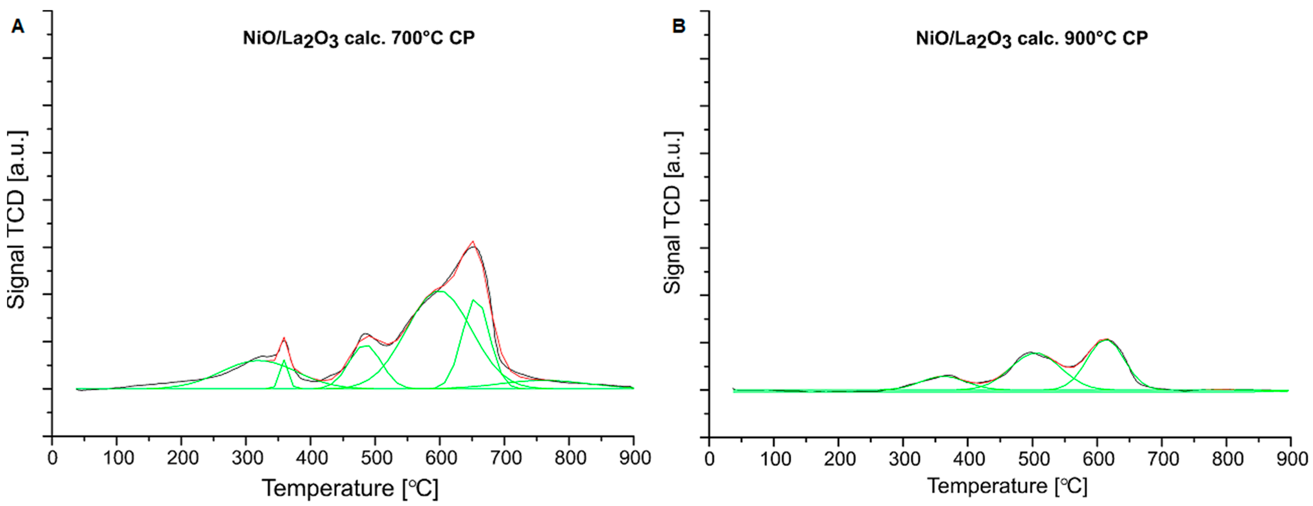
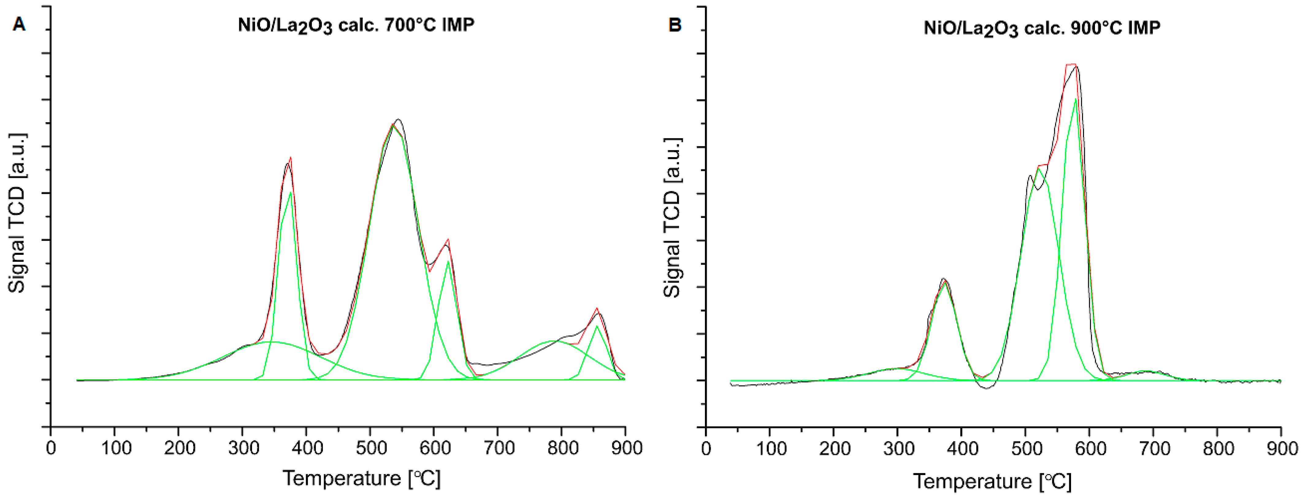
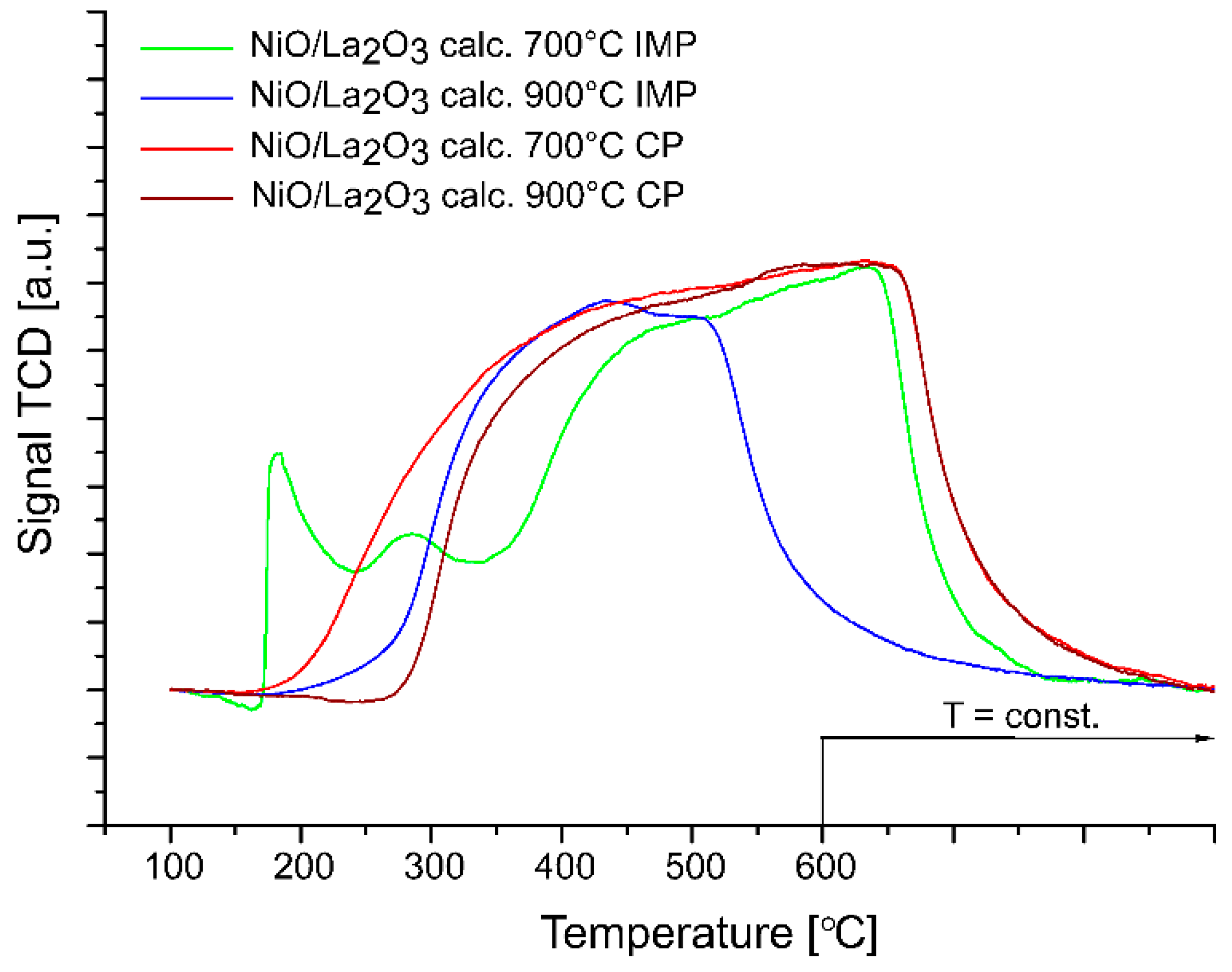
2.2. Reduction Behavior of the Investigated Catalysts

The reduction behavior of the studied NiO/La2O3 catalysts were determined using the temperature-programmed reduction method (TPR-H2). TPR-H2 measurements were performed in order to explain the interactions between the catalyst components. The TPR-H2 profiles recorded for the investigated NiO/La2O3 catalysts are presented in Figure 1 and Figure 2, respectively. The TPR-H2 curve recorded for the NiO/La2O3 calc. 700 °C CP catalyst showed five reduction effects. The first low temperature effects located in the temperature range from 250–350 °C were assigned to the “free” NiO species reduction. This effect was associated with the reduction of NiO species which weakly interacted with the support surface. The next stage (330–380 °C) was attributed to the NiO species reduction, which interacted with the La2O3. The third reduction step visible on the TPR profile was assigned to the reduction of NiO, which interacted strongly with the support compared to the previously described NiO species. The reduction effect located in the temperature range from 520–650 °C was related with the reduction of nickel oxide, which interacted more strongly with the carrier. The high temperature reduction effect observed on the TPR profile above 600 °C was ascribed to the reduction of NiO, which strongly interacted with the support or could be attributed to the perovskite or spinel phases reduction process [9,10,11]. The TPR-H2 profile of the NiO/La2O3 calc. 900 °C CP presented three H2 consumption peaks which were assigned to the reduction of free NiO which interacted both weakly and strongly with the NiO species and the La2O3 [12]. The TPR profile curve recorded for the NiO/La2O3 calc. 700 °C IMP catalyst showed reduction peaks located in the temperature range from 200–700 °C, which was associated with the reduction of free nickel oxides and NiO, which interacted variously with the La2O3 carrier. In addition, the reduction effects above 700 °C were connected with the two steps of LaNiO3 reduction to La2O3 and Ni species according to the following stages [13,14]:
LaNiO 3 + 1 2 H 2 LaNiO 2.5 + 1 2 H 2 O
LaNiO 2.5 + H 2 1 2 La 2 O 3 + Ni + H 2 O
This result corresponded well with the reflexes observed on the X-ray diffraction pattern recorded for the NiO/La2O3 calc. 700 °C IMP catalyst (see the XRD part of the work). The TPR profile of the NiO/La2O3 calc. 900 °C IMP catalyst showed the reduction effects located in the temperature range: 250–650 °C. The observed reduction steps were connected with free NiO or nickel oxides interacting differently with the carrier. On the TPR profile recorded for this system we can distinguish that the reduction peaks assigned to the NiO species interacted, both weakly and strongly, with La2O3. The last H2 consumption peak, at approximately 650 °C, was assigned to the reduction of the La2NiO4 structure [14,15].
Hassiba Messaoudi et al. [15,16] investigated the reduction behavior of LaNiO3 perovskite (noted LN3) and La2NiO4 spinel (noted LN4) catalysts prepared by the sol-gel method and calcined at 1023 K for 6 and 4 h, respectively. TPR-H2 profiles recorded for these systems showed two reduction effects. The first peak was related to the reduction of Ni3+ to Ni2+ (according to following scheme: 2LaNiO3 + H2 → La2Ni2O5 + H2O) and NiO species (for LN4). The second peak was attributed to the reduction of Ni2+ (for perovskite LN3: La2NiO5 and for spinel LN4: La2NiO4) to La2O3 and Ni0 according below scheme:
La2NiO5 + 2H2 → Ni + La2O3 + 2H2O
La2NiO4 + H2 → Ni + La2O3 + H2O
The LN3 catalyst showed the reduction effects in a lower temperature range compared to the LN4 catalyst which proved that the LaNiO3 perovskite system was easier to reduce under the TPR-H2 conditions of measurement. The reducibility results corresponded well with the catalytic activity of these systems in the dry reforming of the methane reaction. The obtained results showed better catalytic performances for the perovskite structure (LN3) due to its high reducibility compared to the spinel catalysts (LN4). Arandia et al. [17] also studied bulk types of nickel catalyst, such as the Ni-La perovskites: LaNiO3 and La2NiO4, respectively. These catalysts were prepared by the auto-combustion method from nickel and lanthanum nitrate solutions, using urea as a fuel. The LaNiO3 and La2NiO4 perovskites systems were calcined at 700 °C. The TPR profiles recorded for the perovskite structure showed two reduction effects. In the case of the LaNiO3 catalyst, these effects were related with the reduction of the Ni3+ to Ni2+ (in La2Ni2O5 species) and of La2Ni2O5 to metallic nickel (Ni0) and lanthanum oxide (La2O3), whereas the reduction behavior of the La2NiO4 system was described as twofold. The authors maintained that the reduction of the La2NiO4 perovskite could occur according to: Ni3+ to Ni2+ and further Ni2+ to Ni0, respectively [18,19,20]. On the other hand, they reported that the reduction of La2NiO4 could also rely on the reduction of excess oxygen in La2NiO4+δ at first and, after that, the reduction of La2NiO4 in one step at approximately 600 °C [21,22]. Furthermore, the reduction effects recorded for the La2NiO4 catalyst were shifted to a higher temperature range compared to LaNiO3 due to the presence of a higher interaction between Ni and La2O3 in the La2NiO4 perovskite catalyst [23]. Matthieu Fleys et al. [24] investigated the reduction behavior of the Ni/La2O3 catalyst prepared by the wet impregnation method and calcined for 5 h at 800 °C in an air atmosphere. They were presented with the TPR analysis for samples that were fresh and those that experienced a reaction of the partial oxidation of methane. The authors observed on the TPR profile recorded for the fresh catalyst two reduction effects which were named α and β, respectively. The α peak with a maximum at 410 °C was related with the reduction of the NiO species to metallic Ni. The next effect (β) was assigned to the reduction of hydroxy or the oxycarbonate species. The TPR profile recorded for the used Ni/La2O3 catalyst showed significantly smaller reduction effects. These phenomena were related with the possibility of catalyst sample reduction during the partial oxidation of methane reaction.
Table 3 presents the results of the deconvolution of the observed reduction peaks and their contribution to the total area of the TPR peaks. Additionally, in Table 3, the maximum of each reduction peak is presented. The NiO/La2O3 CP catalyst calcined at 900 °C presented the reduction effects at a higher temperature range compare to the NiO/La2O3 CP catalyst calcined at 700 °C. This relationship proved that the lower temperature of the calcination process facilitates the reduction process of the NiO/La2O3 catalyst prepared by the co-precipitation method (CP). A more complicated situation was observed in the case of the catalysts prepared by the wet impregnation method (IMP). On the one hand, the NiO/La2O3 IMP catalyst calcined at 900 °C presented the reduction peaks connected with the NiO species, which were differently interacting with their support, and were shifted towards the lower temperature range compared to the NiO/La2O3 IMP catalyst calcined at 700 °C. On the other hand, for this system we also observed a shift in the reduction peaks assigned to the reduction of free NiO, and NiO interacted with the carrier towards a higher temperature range. This reduction behavior corresponded well with the reactivity results of these catalysts studied in the oxy-steam reforming of the LNG process. The NiO/La2O3 calc. 700 IMP catalysts which were the most active system in the OSR-LNG reaction showed the highest contribution of nickel oxide, which weakly interacted with the support or NiO species, with medium-strength interactions with the carrier compared to the rest of the studied catalytic systems. In addition, the reduction peak assigned to the NiO species, which weakly interacted with support, were located at the lowest temperature range compared to the rest of the investigated catalysts. Furthermore, in the case of the NiO/La2O3 calc. 700 IMP system’s contribution to the peaks assigned to the reduction of the NiO species, these strongly interacted with the support. The TPR profiles recorded for the LaNiO3 or NiLa2O4 reduction were also the lowest compared to the rest of the investigated catalysts.

2.3. Specific Surface Area Measurements of Investigated Catalysts

The specific surface area (SSA) measurements were performed for all investigated catalytic systems using the N2 adsorption–desorption method. The values of the BET surface area, monolayer capacity and average pore radius were given in Table 4. The La2O3 support had the lowest BET surface area and the highest average pore radius values. The NiO/La2O3 catalysts exhibited a higher specific surface area and monolayer capacity values and a lower average pore radius value compared to the La2O3 carrier. The NiO/La2O3 catalysts prepared by the co-precipitation method (CP) showed a higher BET surface area compared to the NiO/La2O3 catalysts prepared by the wet impregnation method (IMP). On the other hand, the NiO/La2O3 calc. 700 °C CP and NiO/La2O3 calc. 900 °C CP systems had the lowest value of average pore radius. The highest SSA value, equal to 24.41 m2/g, exhibited the NiO/La2O3 calc. 700 °C CP catalyst. In addition, the catalytic systems calcined at 700 °C showed a higher BET surface area and average pore radius compared to the catalysts calcined at 900 °C and prepared by the same method of synthesis. Among all of the studied catalysts, the NiO/La2O3 calc. 700 °C IMP and the NiO/La2O3 calc. 900 °C CP systems had the highest and the lowest value of average pore radius, equal to 16.31 and 8.43 nm, respectively. These results corresponded well with the reactivity of the catalysts in the OSR-LNG reaction. The SSA measurements clearly showed that the most active system exhibited the highest average pore radius. Additionally, we observed that the NiO/La2O3 calc. 900 °C CP system showed the lowest activity in the OSR-LNG process and had the lowest value of average pore radius. This relationship suggested that the pore radius could determine the catalytic activity in the oxy -steam reforming of LNG reaction.
The N2 adsorption/desorption isotherms obtained for the investigated NiO/La2O3 catalysts are presented in Figure 3. Brunauer, Emett, and Teller classified five types of physical adsorption isotherms which were commonly named BET isotherms [25]. For all studied catalysts, we observed the II type of isotherms, which were related to the formation of a multi-molecular layer. The shape of the hysteresis loop depends on the type of pores presented on the catalyst surface. We observed the first type of hysteresis loop characteristic for pores with a cylindrical shape, various cross-sections and a similar radius. The hysteresis loops of investigated catalysts started from p/p0 = 0.80 and were characteristic of a mesoporous surface.
Messaoudi et al. [15,16] studied the BET surface area and average pore diameter for the LaNiO3 perovskite and La2NiO4 spinel systems prepared by the sol-gel method. The SSA and dpore values for LaNiO3 perovskite were equal to 7.3 m2/g and 4.9 nm, respectively. However, for the La2NiO4 spinel catalyst, the authors observed slightly lower values of the specific surface area and an average pore diameter equal to 5.5 and 4.3 nm. The N2 adsorption-desorption isotherms recorded for the calcined samples were attributed to the IV type of isotherm according to International Union of Pure and Applied Chemistry (IUPAC) classification [26]. The pore size distribution confirmed the mesoporous structure of the tested catalysts. Aitor Arandia et al. [17] also investigated the specific surface area, pore volume and pore diameter for LaNiO3 and La2NiO4 perovskite structures. The LaNiO3 catalyst had SBET, Vpore and dpore equal to 9.2 m2/g, 0.062 cm3/g and 29.5 nm, respectively. However, for La2NiO4 perovskite, the authors observed slightly lower values of these parameters, equal to 7.3 m2/g, 0.012 cm3/g and 6.8 nm, respectively. Fleys et al. [24] compared the BET surface area of the Ni/La2O3 catalyst before and after the partial oxidation of methane reaction. They studied the catalytic system prepared by the wet impregnation method and calcined at 800 °C for 5 h in an air atmosphere. The specific surface area for the spent Ni/La2O3 catalyst was 12.5, compared to 8.5 m2/g obtained for the calcined sample. This result was explained by the sintering process and by the carbon deposit formation on the surface of this system.

2.4. Acidity Measurements of Investigated Catalysts

The acidity properties of La2O3 support and NiO/La2O3 catalysts were studied using the temperature-programmed desorption of ammonia technique (TPD-NH3). The main purpose of these measurements was to determine the donor–acceptor properties of the tested catalytic materials. The TPD-NH3 results are shown in Table 5 and Figure 4, respectively. The La2O3 support had the lowest total acidity values, equal to 0.15 mmol/g. In the case of NiO/La2O3 catalysts, the samples were reduced before each test, at 500 °C in pure hydrogen for 1 h. The acidity results showed that the catalysts prepared by the co-precipitation method (CP) exhibited a higher total acidity compared to the catalysts prepared by the wet impregnation method (IMP). Taking into account the NiO/La2O3 CP systems, the catalyst calcined at a temperature of 700 °C had a lower total acidity value. However, among the NiO/La2O3 IMP systems, the catalyst which exhibited the lowest total acidity value was calcined at 900 °C. The NiO/La2O3 system had the highest value, with a total acidity of 3.73 mmol/g, and was prepared by the co-precipitation method and calcined at 900 °C, while the same system, which was calcinated at 700 °C, exhibited 3.20 mmol of the adsorbed ammonia per gram of the catalyst. It is also worth noting that both systems prepared by the CP method, calcined at 700 and 900 °C, exhibited very similar catalytic activities in the OSR-LNG process. In addition, the NiO/La2O3 system prepared by the co-precipitation method and calcined at 900 °C showed the highest value of a strong acid centre on the catalyst surface. On the other hand, the NiO/La2O3 catalyst prepared by the impregnation method and calcined at 700 °C exhibited the highest activity among all of the investigated catalysts in the OSR-LNG reaction and showed the highest value of the weak acid centres. It was also characterized by the lowest number of acid centers of medium strength compared to the rest of the catalysts.

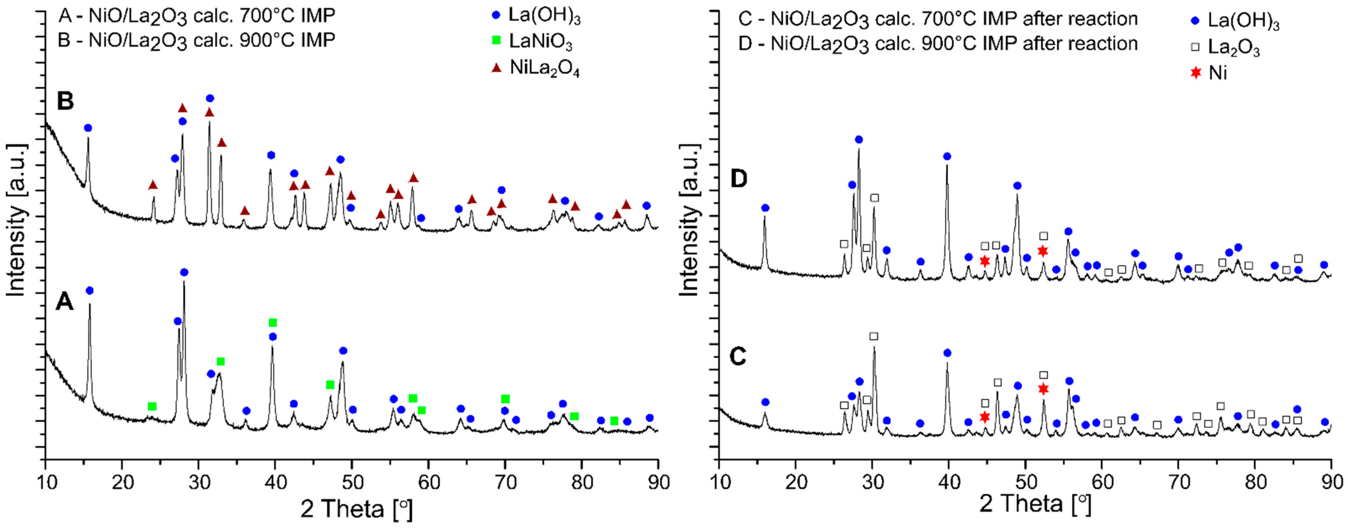
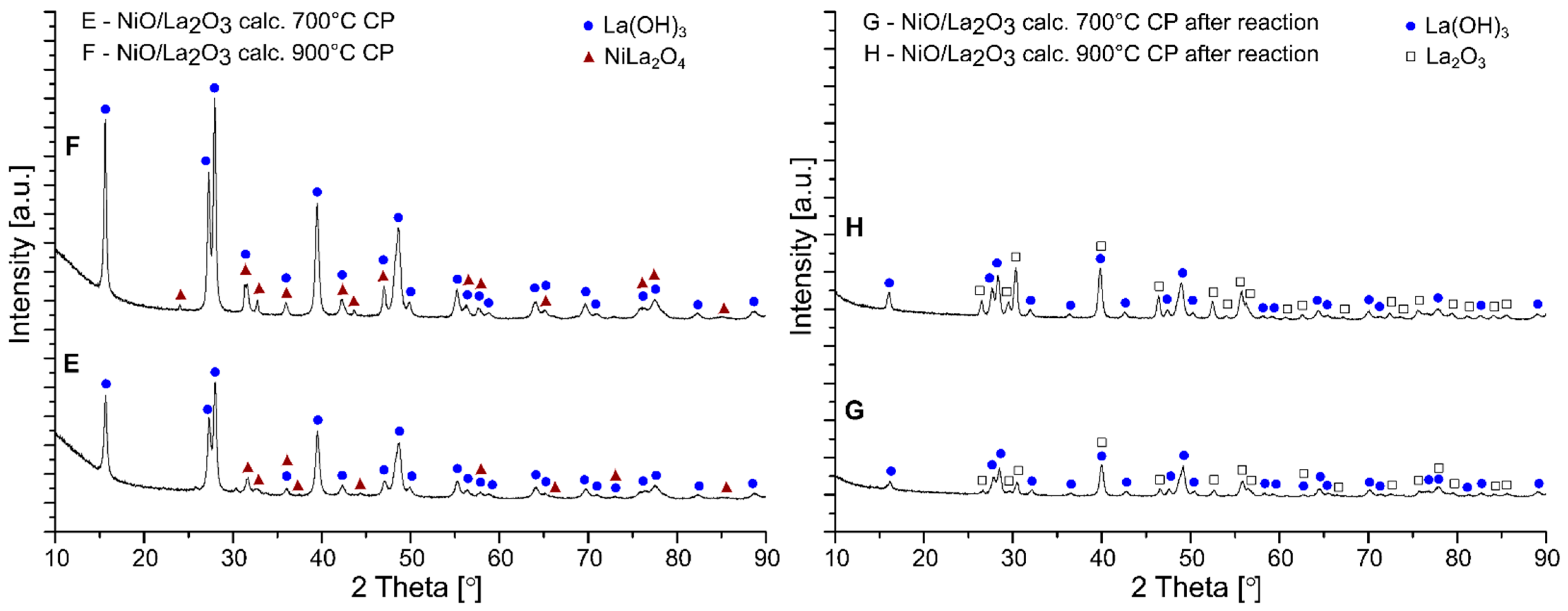
2.5. Phase Composition Studies of Investigated Catalysts

The phase composition studies were carried out for all the investigated NiO/La2O3 catalysts. Figure 5 presents the XRD patterns of the NiO/La2O3 catalysts prepared by impregnation methods and calcined at (line A in Figure 5) 700 °C and (line B in Figure 5) at 900 °C, while line C in Figure 5 and line D in Figure 5 show the diffraction curves for the same catalysts tested in the OSR-LNG reaction. The XRD pattern of the NiO/La2O3 catalyst calcined at 700 °C (line A in Figure 5) confirmed the presence of the La(OH)3 and LaNiO3 phases. The diffraction pattern of the same catalyst after the OSR-LNG reaction (line C in Figure 5) showed the presence of the diffraction peaks assigned to the La(OH)3, La2O3 and metallic Ni phases. The X-ray diffraction curve recorded for the NiO/La2O3 calc. 900 °C IMP catalyst (Line B in Figure 5) demonstrated the crystallographic phases assigned to the La(OH)3 and NiLa2O4 structure. On the other hand, the XRD curve of this catalyst after the OSR-LNG reaction (line D in Figure 5) showed peaks attributed to the La(OH)3, La2O3 and metallic Ni phases. In the next part of the phase composition studies, analogical measurements were performed for the NiO/La2O3 catalysts prepared by the co-precipitation method and calcined in an air atmosphere at 700 °C (line E in Figure 6) and at 900 °C (line F in Figure 6) were carried out and the results are given in line E in Figure 6 and line F in Figure 6, respectively. The XRD patterns recorded for those investigated catalysts showed the diffraction peaks assigned to the La(OH)3 and NiLa2O4 phases. In terms of the same catalyst tested in the OSR-LNG reaction, the phase compositions studies (line G in Figure 6 and line H in Figure 6) showed the reflexes attributed to the La(OH)3 and La2O3 phases. The presence of the Ni phase on the surface of the spent catalysts prepared by the wet impregnation method (IMP) could be responsible for their higher activity in the the OSR-LNG reaction compared to the catalytic material prepared by the co-precipitation method. The XRD analysis of the most active NiO/La2O3 calc. 700 °C IMP system showed the presence of LaNiO3 structure on the catalyst surface which can explain its superior activity in the OSR-LNG process. The reduction process of this compound at a higher temperature generated metallic nickel particles which were the active species and played an important role during the OSR-LNG process.
In a further part of the phase composition study, the percentage of crystallographic phases present in the investigated systems was calculated based on the XRD results. The percentage of each phase in the studied systems are given in Table 6. Taking into account the NiO/La2O3 catalysts produced by the co-precipitation (CP) method, the catalyst calcined at 700 °C consisted mainly of the La(OH)3 phase, and a small amount of the spinel phase was also detected. The increase in the calcination temperature, by up to 900 °C, resulted in an increase in the quantity of the spinel structure in the catalytic material. However, the La(OH)3 phase represented a majority (about 90%) compared to the NiLa2O4 phase, in the case of these catalysts. After the OSR-LNG reaction, we observed a significant decrease in the percentage of La(OH)3 phase in favor of the formation of La2O3. Additionally, the NiO/La2O3 calc. catalyst was consumed. Moreover, the catalyst tested in the reaction and calcined at 900 °C showed a higher content of the La2O3 phase compared to the La(OH)3 phase.
In the case of the NiO/La2O3 catalysts prepared by the wet impregnation method (IMP), only the NiO/La2O3 calc. 700 °C IMP system exhibited the presence of LaNiO3, rather than NiLa2O4, next to La(OH)3 phase. For the NiO/La2O3 system prepared via the impregnation method and calcined at higher temperature (900 °C), a larger amount of the NiLa2O4 phase was observed compared to the La(OH)3 phase, while in the case of the spent NiO/La2O3 IMP catalysts, we observed an additional metallic Ni phase on the XRD diffractograms. The NiO/La2O3 calc. 700 IMP catalyst, after the OSR-LNG reaction, showed a higher contribution of the La2O3 phase than the La(OH)3 phase, which simultaneously showed a higher contribution of the metallic Ni phase compared to the NiO/La2O3 IMP catalyst calcined at 900 °C. These results clearly showed that the percentage contribution of crystallographic phases also had a great influence on the activity of the investigated NiO/La2O3 catalysts in the oxy-steam reforming of the LNG reaction. Moreover, the presence of the Ni and LaNiO3 phases and their quantities had a crucial impact on the catalytic activity of the investigated materials in the studied process.
The crystallite sizes of the phase components were evaluated for the spent NiO/La2O3 IMP catalysts and are presented in Table 7. The crystallites size of the phase components were calculated based on the Scherrer’s formula. More active catalysts in the oxy-steam reforming of the LNG reaction, i.e., NiO/La2O3 catalysts prepared by the wet impregnation method (IMP), showed the presence of smaller metallic nickel crystallites on the surface of the spent catalyst. The NiO/La2O3 calc. 900 °C IMP catalyst had a slightly higher size of Ni crystallite equal to 27 nm. This result could suggest that the most active system in OSR-LNG process (NiO/La2O3 calc. 700 IMP) exhibited lower metallic Ni crystallite sizes, which could determine its reactivity in the studied reaction. In addition, the obtained results showed that, the size of the La2O3 crystallites was larger for the system calcined at 900 °C, while for La(OH)3, no changes in the crystallite sizes were observed. These results alsoconfirmed the increase in the calcination temperature result in the growth of the catalyst crystallinity.
Hassiba Messaoudi et al. [15,16] studied the phase composition of the LaNiO3 perovskite (LN3) and La2NiO4 spinel (LN4) catalysts prepared by the sol-gel method using the XRD technique. The X-ray diffractogram recorded for LN3, calcined in a catalytic system, showed the presence of the perovskite structure on the XRD pattern recorded for this material. However, the XRD pattern of the LN3 sample after reduction showed the presence of La2O3 and metallic Ni phases. The authors also performed the phase composition analysis of the LN4 calcined catalyst and confirmed the formation of the La2NiO4 crystallographic phase for this catalytic material. The diffraction pattern recorded for the reduced system, as well as for the LN3 system, showed the presence of the diffraction peaks assigned to the La2O3 and Ni phases. Arandia et al. [17] investigated the phase composition of the LaNiO3 and La2NiO4 perovskite catalysts. The XRD patterns recorded for calcined catalytic systems confirmed the presence of the LaNiO3 phase for the LaNiO3 perovskite and the LaNiO3 and La2O3 phases for the La2NiO4 system. The X-ray diffraction patterns recorded for both reduced samples showed the diffraction peaks attributed to the metallic Ni and La2O3 phases. The Ni0 crystallite sizes calculated from the Scherrer equation were 14.2 and 11.6 for LaNiO3 and La2NiO4 perovskite, respectively. The higher value of metallic nickel crystallite size in the case of the LaNiO3 catalyst was related to the higher amount of Ni in the case of the LaNiO3 system which resulted in a poorer metallic nickel dispersion on the surface of this system. The authors corelated the XRD results with the activity and stability of the investigated LaNiO3 and La2NiO4 perovskite catalysts in the oxy-steam reforming of bio-oil process. They reported that the Ni0 crystallite size played a crucial role in this process and determined the reactivity of the studied catalysts. Fleys et al. [24] studied the phase composition of the Ni/La2O3 catalyst synthesized by the wet impregnation method. The XRD pattern recorded for the calcined Ni/La2O3 sample showed the presence of the La(OH)3, La(OH)CO3 and NiLa2O4 phases. These authors also studied the phase composition of the Ni/La2O3 catalyst tested in the partial oxidation of methane process. The results showed that the spent sample exhibited the existence of the diffraction peaks, assigned to the La(OH)3 and La2O3 phases, on the XRD pattern. The authors explained the lack of the Ni or NiO phases in the diffraction pattern, as the nickel content in the catalyst was too low to detect by conventional XRD techniques and other research methods are required to observe these phases. Muroyama et al. [27] also investigated the phase composition of the Ni/La2O3 catalysts prepared by various methods, including impregnation and co-precipitation, respectively. They compared the XRD patterns recorded for the Ni/La2O3-calcined catalysts with a various nickel loading (from 10 to 70%). The XRD analysis of 10% of Ni/La2O3- and 20% of Ni/La2O3-calcined catalysts showed the presence of the La(OH)3, La2O3 and LaNiO3 phases on the XRD pattern recorded for these systems. Above 30% wt. of nickel loading, in the case of Ni systems, the NiO phase was detected on the XRD curves recorded for the studied catalysts. The authors also observed for the Ni/La2O3 catalysts with a high nickel loading from 40 to 70% the presence of the NiO and LaNiO3 phases on the diffraction patterns. The XRD pattern recorded for the nickel catalyst prepared by the co-precipitation method showed the diffraction peaks attributed to the La(OH)3 and LaNiO3 phases. The influence of calcination temperature on the composition of Ni/La2O3 catalysts was also examined for samples prepared by the wet impregnation method. The authors also performed the phase composition studies for catalytic systems calcined in the temperature range: 400–800 °C. The authors observed, in the case of the Ni/La2O3 catalyst calcined at 700 and 800 °C, the presence of the LaNiO3 phase on the XRD pattern, the crystallinity of which increased with the increase in calcination temperature, and the crystallographic phase itself became more difficult to reduce.

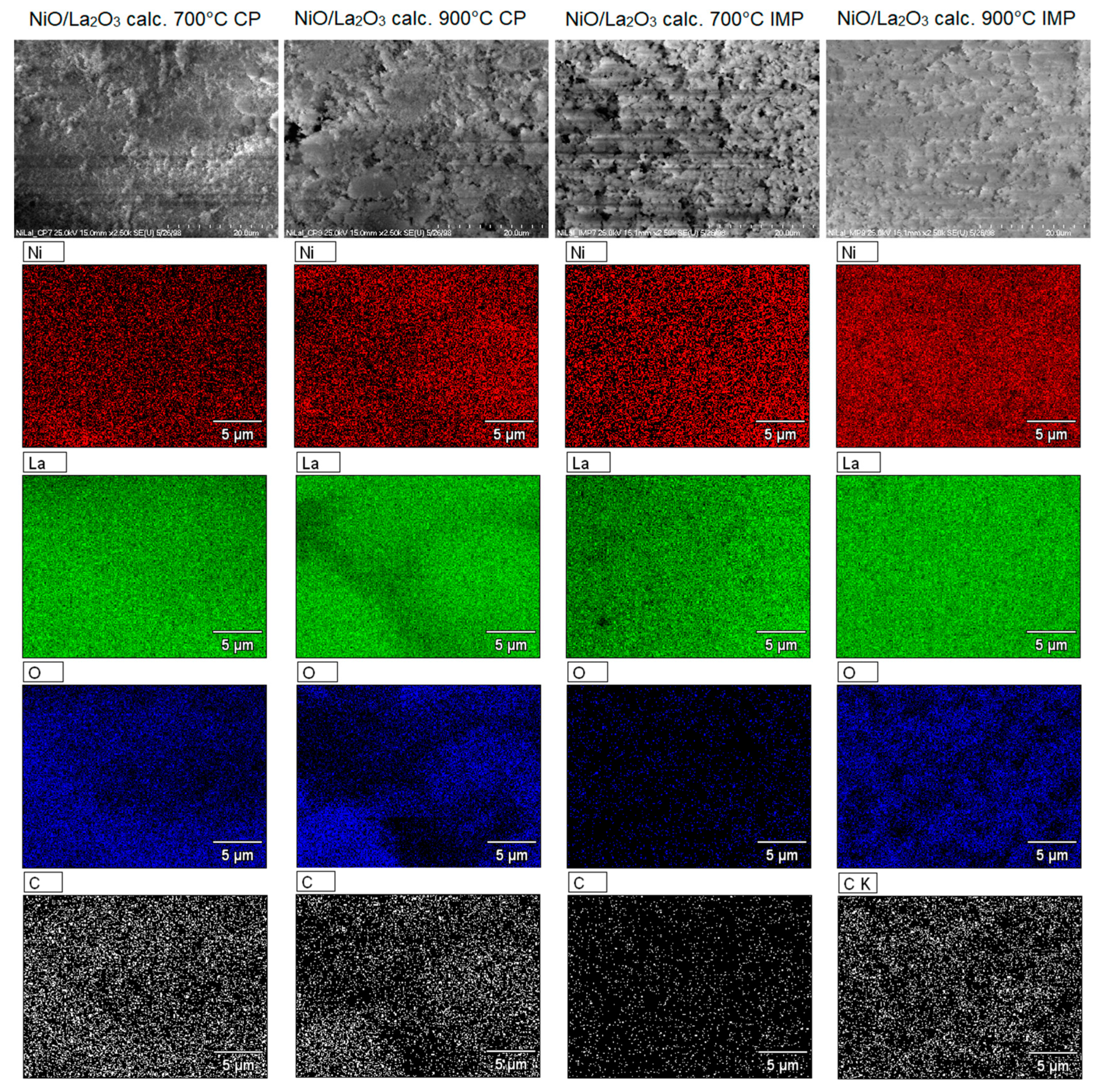
2.6. SEM-EDS Measurements of Investigated Catalysts

The surface morphology of the investigated NiO/La2O3 catalysts were investigated using scanning electron microscopy (SEM) equipped with an energy dispersion spectrometer detector (EDS). The obtained results were given as SEM images which are presented in Figure 7 for the tested catalysts in the OSR-LNG reaction. SEM images obtained for the investigated catalysts confirmed their composition. The presence of the elements, nickel, lanthanum and oxygen, on the catalyst surfaces was confirmed. Additionally, SEM-EDS measurements showed the presence of carbon which confirmed the carbon deposit formations on the catalyst surfaces during the OSR-LNG reaction. In the case of the NiO/La2O3 calc. 700 IMP catalyst, we observed the lowest amount of the carbon on the surface compared to the rest of the studied catalyst systems. This tendency explained the highest activity of this catalytic system in OSR-LNG reaction. The NiO/La2O3 IMP catalysts were characterized by a greater amount and better dispersion of nickel particles on their surface. These results also indicated that the size of the nickel particles affected the activity of the studied catalysts in the OSR-LNG process, whereas, in the case of the catalysts prepared by the co-precipitation method (CP), a part of the nickel active species was covered by a lanthanum species which could explain the lower activity of these catalysts in the studied process.

3. Materials and Methods

3.1. Supports and Catalysts Preparation

NiO/La2O3 catalysts were synthesized by the wet impregnation (IMP) and co-precipitation (CP) methods. NiO and La2O3 oxides precursors were nickel (II) nitrate hexahydrate and lanthanium nitrate hexahydrate, respectively. In the case of catalytic systems prepared by co-precipitation method, an aqueous solution of appreciate precursor salts were mixed in molar ratio Ni:La equal to 1:2. Thereafter, the obtained solutions were vigorously stirred. The precipitation process was carried out using an ammonia solution as a precipitation agent until the pH was reached the value was between 10–11. The obtained nickel or lanthanum hydroxides were filtrated, washed, and dried in an air atmosphere at 120 °C for 2 h. Finally, the NiO/La2O3 catalysts were calcined in an air atmosphere for 4 h at 700 and 900 °C, respectively. The catalysts obtained by this method were named NiO/La2O3 calc. 700 °C CP and NiO/La2O3 calc. 900 °C CP. Figure 8 illustrates schematically the synthesis steps of the NiO/La2O3 catalysts prepared via the co-precipitation method.
Subsequently, NiO/La2O3 catalysts were prepared by the wet impregnation method (see Figure 9). The La2O3 oxide support was synthesized by the precipitation method. The precipitate was formed using an ammonia solution which was added dropwise until the pH of the solution reached the value of 10. The lanthanum hydroxide was filtrated, washed, and dried in an air atmosphere at 120 °C for 2 h. Finally, the La2O3 carrier was calcined for 4 h at 700 °C. The NiO oxide was introduced on the obtained La2O3 support surfaces using a nickel (II) nitrate hexahydrate precursor. The molar ratio Ni:La in NiO/La2O3 catalysts was also equal to 1:2. The impregnation process took 12 h. The catalytic materials were then dried for 2 h at 80 °C and calcined in an air atmosphere for 4 h at 700 and 900 °C. The catalysts obtained by this method were named NiO/La2O3 calc. 700 °C IMP and NiO/La2O3 calc. 900 °C IMP, respectively.

3.2. Characterization of the Catalytic Materials

The reducibility of the NiO/La2O3 catalysts was investigated using the temperature programmed reduction technique (TPR-H2) using an automatic AMI-1 instrument (Altamira Instruments, Pittsburgh, PA, USA). The reduction behavior of the catalytic materials were determined in the temperature range of 35–900 °C. The specific surface area and porosity of the investigated NiO/La2O3 catalysts was determined using the BET method. The analyses were carried out in ASAP 2020 Micrometrics apparatus (Surface Area and Porosity Analyzer, Micromeritics Instrument Corporation, Norcross, GA, USA). The distributions of the pore sizes were determined using BJH method. The acidic properties of the catalytic materials were studied by temperature programmed desorption of ammonia technique (TPD-NH3). In each experiment, the catalyst samples were reduced at 500 °C in a mixture of 5% H2–95% Ar and the TCD detector monitored the concentration of ammonia in the temperature range of 100–600 °C. The phase composition of the synthesized catalysts were determined using X-ray diffraction technique in a PANalytical X’Pert Pro MPD diffractometer (Malvern Panalytical Ltd., Malvern, United Kingdom) in Bragg-Brentano reflecting geometry. The morphology and distribution of the elements on the catalyst surfaces were studied using a S-4700 scanning electron microscope HITACHI (Tokyo, Japan), equipped with an energy dispersive spectrometer (ThermoNoran, Madison, WI, USA) (SEM-EDS). The samples were not sputtered with carbon before the measurements.

3.3. Catalytic Activity Measurements in Oxy-Steam Reforming of the Liqufied Natural Gas Reaction (OSR-LNG)

The catalytic activity tests of the studied NiO/La2O3 catalysts were carried out in the oxy-steam reforming of liquefied natural gas reaction (OSR-LNG). The LNG mixture contains a hydrocarbons such as: methane (5%), ethane (0.4%), propane (0.2%) and butane (0.05%). The catalytic tests were performed in a quartz microreactor in the temperature range 400–900 °C under atmospheric pressure. The weight of a catalyst sample was 0.2 g in all cases. The catalytic activity was measured after 30 min of running the process. The total gas flow rate of the reaction mixture was 51 cm3/min. The composition of the reaction mixture was constant during the activity test. During all catalytic activity measurements a model gas mixture of LNG (5% CH4, 0.4% C2H6, 0.2% C3H8, 0.05% C4H10 and 94.35% Ar) and a mixture of 5%O2/95%Ar were used. The molar ratio between reagents in the reaction mixture was CH4:H2O:O2 = 1:2.7:0.35, respectively. The analysis of the gaseous products produced in the OSR-LNG reaction were monitored using gas chromatographs equipped with TCD and FID detectors. The catalytic activity results were expressed as hydrocarbons (methane, ethane, propane, butane) conversion, and as selective to CO and CO2 and hydrogen yield, which were calculated based on the following Equations (5)–(8):
C X H Y Conv . = ( 1 n out C X H Y n in C X H Y ) × 100 %
CO Sel . = ( n out CO n out CO + n out CO 2 ) × 100 %
CO 2 Sel . = ( n out CO 2 n out CO + n out CO 2 ) × 100 %
H 2 Yield = ( n out H 2 2.73 ( n in C X H Y ) ( n out C X H Y ) ) × 100 %
where:
  • n in C X H Y —the moles of hydrocarbon at the reactor inlet;
  • n out C X H Y —the moles of hydrocarbon at the reactor outlet;
  • n out CO —the moles of the CO at the reactor outlet;
  • n out CO 2 —the moles of the CO2 at the reactor outlet;
  • n out H 2 —the moles of the H2 at the reactor outlet;
  • ( n in C X H Y ) —the sum of the moles of the hydrocarbons the reactor inlet;
  • ( n out C X H Y ) —the sum of the moles of the hydrocarbons at the reactor outlet.

4. Conclusions

In the present study, hydrogen production via the oxy-steam reforming of LNG reaction (OSR-LNG) was carried out over a series of NiO/La2O3 catalysts. The obtained results indicated the influence of the preparation method and the calcination process temperature on the activity of the tested catalytic systems. The reactivity measurements showed that the nickel catalyst prepared by the conventional wet impregnation method exhibited a higher activity compared to the catalyst system prepared by the co-precipitation method. In addition, it was proven that the catalytic systems calcined at 700 °C showed a higher activity in the OSR-LNG process. The catalytic activity tests pointed out that the most active system in the OSR-LNG process at 900 °C was the NiO/La2O3 system prepared via the impregnation method and calcined at 700 °C which exhibited the total LNG components conversion and the highest hydrogen yield compared to the rest of the studied catalysts. The highest activity of the NiO/La2O3 calc. 700 IMP catalyst was explained by its phase composition, reducibility and the average crystallite sizes of metallic nickel present on the catalyst surface. The presence of the LaNiO3 as a one of the phase components of the calcined catalyst, facilitated the formation of metallic nickel particles during the reduction process which took place during the OSR-LNG reaction at a higher temperature, leading to the high catalytic activity of the NiO/La2O3 calc. 700 IMP catalyst. SEM-EDS measurements also confirmed the formation of the smallest amount of carbon deposit formed on the surface of the most active catalytic system. The results presented in this article may contribute to broadening the available knowledge about nickel catalysts applied in the LNG reforming process.

Author Contributions

The work was designed and presented by M.M., W.M., M.I.S.-J. and P.M. All authors have read and agreed to the published version of the manuscript.

Funding

The project was funded by the National Science Centre (Opus Programme—Grant No. 2018/29/B/ST8/01317).

Conflicts of Interest

The authors declare no conflict of interest.

References

  1. Schwarz, J.A.; Contescu, C.; Contescu, A. Methods for Preparation of Catalytic Materials. Chem. Rev. 1995, 95, 477–510. [Google Scholar] [CrossRef]
  2. Irandoust, A.; Haghtalab, A. A Hybrid Reduction–Impregnation Method in Preparation of Co–Ru/γ-Al2O3 Catalyst for Fischer–Tropsch Synthesis. Catal. Lett. 2017, 147, 2967–2981. [Google Scholar] [CrossRef]
  3. Sietsma, J.R.A.; Jos van Dillen, A.; de Jongh, P.E.; de Jong, K.P. Application of ordered mesoporous materials as model supports to study catalyst preparation by impregnation and drying. In Studies in Surface Science and Catalysis; Gaigneaux, E.M., Devillers, M., De Vos, D.E., Hermans, S., Jacobs, P.A., Martens, J.A., Ruiz, P., Eds.; Elsevier: Amsterdam, The Netherlands, 2006; Volume 162, pp. 95–102. [Google Scholar]
  4. Yamada, Y.; Akita, T.; Ueda, A.; Shioyama, H.; Kobayashi, T. Instruments for preparation of heterogeneous catalysts by an impregnation method. Rev. Sci. Instrum. 2005, 76, 62226. [Google Scholar] [CrossRef]
  5. Li, G.; Hu, L.; Hill, J.M. Comparison of reducibility and stability of alumina-supported Ni catalysts prepared by impregnation and co-precipitation. Appl. Catal. A Gen. 2006, 301, 16–24. [Google Scholar] [CrossRef]
  6. Liu, F.; Xu, S.; Cao, L.; Chi, Y.; Zhang, T.; Xue, D. A Comparison of NiMo/Al2O3 Catalysts Prepared by Impregnation and Coprecipitation Methods for Hydrodesulfurization of Dibenzothiophene. J. Phys. Chem. C 2007, 111, 7396–7402. [Google Scholar] [CrossRef]
  7. Pereira, A.L.C.; Berrocal, G.J.P.; Marchetti, S.G.; Albornoz, A.; de Souza, A.O.; Rangel, M.d.C. A comparison between the precipitation and impregnation methods for water gas shift catalysts. J. Mol. Catal. A Chem. 2008, 281, 66–72. [Google Scholar] [CrossRef]
  8. Talati, A.; Haghighi, M.; Rahmani, F. Impregnation vs. coprecipitation dispersion of Cr over TiO2 and ZrO2 used as active and stable nanocatalysts in oxidative dehydrogenation of ethane to ethylene by carbon dioxide. RSC Adv. 2016, 6, 44195–44204. [Google Scholar] [CrossRef]
  9. Oemar, U.; Ang, M.L.; Hidajat, K.; Kawi, S. Enhancing performance of Ni/La2O3 catalyst by Sr-modification for steam reforming of toluene as model compound of biomass tar. RSC Adv. 2015, 5, 17834–17842. [Google Scholar] [CrossRef]
  10. Oemar, U.; Hidajat, K.; Kawi, S. Role of catalyst support over PdO–NiO catalysts on catalyst activity and stability for oxy-CO2 reforming of methane. Appl. Catal. A Gen. 2011, 402, 176–187. [Google Scholar] [CrossRef]
  11. Yu, Y.; Gan, Y.-M.; Huang, C.; Lu, Z.-H.; Wang, X.; Zhang, R.; Feng, G. Ni/La2O3 and Ni/MgO–La2O3 catalysts for the decomposition of NH3 into hydrogen. Int. J. Hydrog. Energy 2020, 45, 16528–16539. [Google Scholar] [CrossRef]
  12. Kathiraser, Y.; Thitsartarn, W.; Sutthiumporn, K.; Kawi, S. Inverse NiAl2O4 on LaAlO3–Al2O3: Unique Catalytic Structure for Stable CO2 Reforming of Methane. J. Phys. Chem. C 2013, 117, 8120–8130. [Google Scholar] [CrossRef]
  13. Barbero, J.; Peña, M.A.; Campos-Martin, J.M.; Fierro, J.L.G.; Arias, P.L. Support Effect in Supported Ni Catalysts on Their Performance for Methane Partial Oxidation. Catal. Lett. 2003, 87, 211–218. [Google Scholar] [CrossRef]
  14. Requies, J.; Cabrero, M.A.; Barrio, V.L.; Güemez, M.B.; Cambra, J.; Arias, P.L.; Pérez-Alonso, F.J.; Ojeda, M.; Peña, M.A.; Fierro, J.L.G. Partial oxidation of methane to syngas over Ni/MgO and Ni/La2O3 catalysts. Appl. Catal. A Gen. 2005, 289, 214–223. [Google Scholar] [CrossRef]
  15. Messaoudi, H.; Thomas, S.; Slyemi, S.; Djaidja, A.; Barama, A. Syngas Production via Methane Dry Reforming over La-Ni-Co and La-Ni-Cu Catalysts with Spinel and Perovskite Structures. Bull. Chem. React. Eng. Catal. 2020, 15, 885–897. [Google Scholar] [CrossRef]
  16. Messaoudi, H.; Thomas, S.; Djaidja, A.; Slyemi, S.; Barama, A. Study of LaxNiOy and LaxNiOy/MgAl2O4 catalysts in dry reforming of methane. J. CO2 Util. 2018, 24, 40–49. [Google Scholar] [CrossRef]
  17. Arandia, A.; Remiro, A.; García, V.; Castaño, P.; Bilbao, J.; Gayubo, A.G. Oxidative Steam Reforming of Raw Bio-Oil over Supported and Bulk Ni Catalysts for Hydrogen Production. Catalysts 2018, 8, 322. [Google Scholar] [CrossRef] [Green Version]
  18. Maneerung, T.; Hidajat, K.; Kawi, S. LaNiO3 perovskite catalyst precursor for rapid decomposition of methane: Influence of temperature and presence of H2 in feed stream. Catal. Today 2011, 171, 24–35. [Google Scholar] [CrossRef]
  19. Lin, K.-H.; Wang, C.-B.; Chien, S.-H. Catalytic performance of steam reforming of ethanol at low temperature over LaNiO3 perovskite. Int. J. Hydrog. Energy 2013, 38, 3226–3232. [Google Scholar] [CrossRef]
  20. Moradi, G.R.; Rahmanzadeh, M.; Khosravian, F. The effects of partial substitution of Ni by Zn in LaNiO3 perovskite catalyst for methane dry reforming. J. CO2 Util. 2014, 6, 7–11. [Google Scholar] [CrossRef]
  21. Wei, T.; Liu, B.; Jia, L.; Li, R. Perovskite materials for highly efficient catalytic CH4 fuel reforming in solid oxide fuel cell. Int. J. Hydrog. Energy 2021, 46, 24441–24460. [Google Scholar] [CrossRef]
  22. Li, P.; Yu, B.; Li, J.; Yao, X.; Zhao, Y.; Li, Y. A single layer solid oxide fuel cell composed of La2NiO4 and doped ceria-carbonate with H2 and methanol as fuels. Int. J. Hydrog. Energy 2016, 41, 9059–9065. [Google Scholar] [CrossRef] [Green Version]
  23. Guo, C.; Zhang, J.; Zhang, X. Comparative study of LaNiO3 and La2NiO4 catalysts for partial oxidation of methane. React. Kinet. Catal. Lett. 2008, 95, 89. [Google Scholar] [CrossRef]
  24. Fleys, M.; Simon, Y.; Swierczynski, D.; Kiennemann, A.; Marquaire, P.-M. Investigation of the Reaction of Partial Oxidation of Methane over Ni/La2O3 Catalyst. Energy Fuels 2006, 20, 2321–2329. [Google Scholar] [CrossRef]
  25. Khalfaoui, M.; Knani, S.; Hachicha, M.A.; Lamine, A.B. New theoretical expressions for the five adsorption type isotherms classified by BET based on statistical physics treatment. J. Colloid Interface Sci. 2003, 263, 350–356. [Google Scholar] [CrossRef]
  26. Leofanti, G.; Padovan, M.; Tozzola, G.; Venturelli, B. Surface area and pore texture of catalysts. Catal. Today 1998, 41, 207–219. [Google Scholar] [CrossRef]
  27. Muroyama, H.; Saburi, C.; Matsui, T.; Eguchi, K. Ammonia decomposition over Ni/La2O3 catalyst for on-site generation of hydrogen. Appl. Catal. A Gen. 2012, 443, 119–124. [Google Scholar] [CrossRef]
Figure 1. TPR-H2 profiles of NiO/La2O3 catalysts prepared by co-precipitation method and calcined at 700 °C (A) and 900 (B) °C in an air atmosphere for 4 h.
Catalysts 11 01174 g001
Figure 2. TPR-H2 profiles of NiO/La2O3 catalysts prepared by wet impregnation method and calcined at 700 °C (A) and 900 (B) °C in an air atmosphere for 4 h.
Catalysts 11 01174 g002
Figure 3. Nitrogen adsorption-desorption isotherms for NiO/La2O3 catalysts.
Catalysts 11 01174 g003
Figure 4. The temperature programmed desorption of ammonia profiles recorded for NiO/La2O3 catalysts reduced in hydrogen atmosphere for 1 h at 500 °C.
Catalysts 11 01174 g004
Figure 5. XRD diffraction patterns recorded for the NiO/La2O3 catalysts prepared by wet impregnation method and calcined in an air atmosphere for 4 h at 700 and 900 °C and for spent systems.
Catalysts 11 01174 g005
Figure 6. XRD diffraction patterns recorded for the NiO/La2O3 catalysts prepared by co-precipitation method and calcined in an air atmosphere for 4 h at 700 and 900 °C and for spent systems.
Catalysts 11 01174 g006
Figure 7. SEM images of investigated catalysts being after OSR-LNG reaction.
Catalysts 11 01174 g007
Figure 8. Synthesis diagram of NiO/La2O3 CP catalysts calcined in air atmosphere for 4 h at 700 °C and 900 °C.
Catalysts 11 01174 g008
Figure 9. Synthesis diagram of NiO/La2O3 IMP catalysts calcined in air atmosphere for 4 h at 700 °C and 900 °C.
Catalysts 11 01174 g009
Table 1. Conversion values of the hydrocarbons obtained in the oxy-steam reforming of liquefied natural gas (LNG) process over NiO/La2O3 catalysts.
CatalystsTemp
[°C]
Methane
Conversion
[%]
Ethane
Conversion
[%]
Propane
Conversion
[%]
Butane
Conversion
[%]
NiO/La2O3
calc. 700 °C
CP
40031343744
50037607891
60043688595
700457088100
9006093100100
NiO/La2O3
calc. 900 °C
CP
40034363836
50031384448
60038647991
70046698693
900578699100
NiO/La2O3
calc. 700 °C
IMP
40033344044
50035435568
60038577387
700648796100
900100100100100
NiO/La2O3
calc. 900 °C
IMP
40033363946
50035445468
60038607783
700396281100
900100100100100
Table 2. The hydrogen yield and selectivity values to CO and CO2 obtained in the oxy-steam reforming of LNG process over NiO/La2O3 catalysts.
CatalystsTemp
[°C]
CO
Selectivity
[%]
CO2
Selectivity
[%]
H2
Yield
[%]
NiO/La2O3
calc. 700 °C
CP
40001000
50001004
60001004
700010011
900712946
NiO/La2O3
calc. 900 °C
CP
40001000
50001000
60001003
70001002
900742639
NiO/La2O3
calc. 700 °C
IMP
40001000
50001000
60001000
700653529
900901056
NiO/La2O3
calc. 900 °C
IMP
40001000
50001000
60001001
700010020
90098254
Table 3. Reduction data for the investigated NiO/La2O3 catalysts.
CatalystsPeak Contribution to the Overall TPR Peak Area (%)
I-Peak (Tmax)II-Peak (Tmax)III-Peak (Tmax)IV-Peak (Tmax)V-Peak (Tmax)VI-Peak (Tmax)
NiO/La2O3
calc. 700 °C
CP
0.16
(325 °C)
0.02
(360 °C)
0.11
(487 °C)
0.47
(585 °C)
0.18
(656 °C)
0.06
(807 °C)
NiO/La2O3
calc. 900 °C
CP
-0.14
(371 °C)
0.43
(506 °C)
0.43
(614 °C)
--
NiO/La2O3
calc. 700 °C
IMP
0.14
(311 °C)
0.14
(369 °C)
0.49
(548 °C)
0.09
(626 °C)
0.10
(807 °C)
0.04
(862 °C)
NiO/La2O3
calc. 900 °C
IMP
0.04
(355 °C)
0.14
(377 °C)
0.44
(512 °C)
0.36
(582 °C)
0.02
(713 °C)
-
Table 4. The specific surface area, monolayer capacity and average pore size for La2O3 support and NiO/La2O3 catalysts.
MaterialsBET Surface Area
[m2/g]
Monolayer Capacity
[cm3/g]
Average Pore Radius
[nm]
La2O3
calc. 700 °C
0.440.00219.93
NiO/La2O3
calc. 700 °C
CP
24.410.14411.94
NiO/La2O3
calc. 900 °C
CP
7.890.0348.43
NiO/La2O3
calc. 700 °C
IMP
4.990.03516.31
NiO/La2O3
calc. 900 °C
IMP
3.050.01613.08
Table 5. The amount of NH3 adsorbed on the surface of NiO/La2O3 catalysts reduced at 500 °C in pure hydrogen for 1 h calculated from the surface under the peaks recorded during the TPD-NH3 measurements.
MaterialsTotal Acidity [mmol/g]Weak Centers [mmol/g]Medium Centers [mmol/g]Strong Centers [mmol/g]
180–600 °C180–300 °C300–450 °C450–600 °C
La2O3
calc. 700 °C
0.150.020.110.02
NiO/La2O3
calc. 700 °C
CP
3.200.331.231.64
NiO/La2O3
calc. 900 °C
CP
3.730.021.242.47
NiO/La2O3
calc. 700 °C
IMP
3.140.471.061.61
NiO/La2O3
calc. 900 °C
IMP
2.120.161.280.68
Table 6. The percentage contribution of crystallographic phases determined for the investigated catalysts after calcination process and the spent catalysts in the OSR-LNG reaction calculated based on the XRD results.
MaterialsPercentage Contribution of the Phases [wt.%]
After calcinationNiO/La2O3
calc. 700 °C CP
La(OH)393
NiLa2O47
NiO/La2O3
calc. 900 °C CP
La(OH)388
NiLa2O412
NiO/La2O3
calc. 700 °C IMP
La(OH)369
LaNiO331
NiO/La2O3
calc. 900 °C IMP
La(OH)345
NiLa2O455
After OSR-LNG reactionNiO/La2O3
calc. 700 °C CP
La(OH)360
La2O340
NiO/La2O3
calc. 900 °C CP
La(OH)345
La2O355
NiO/La2O3
calc. 700 °C IMP
La(OH)334
La2O359
Ni7
NiO/La2O3
calc. 900 °C IMP
La(OH)355
La2O339
Ni6
Table 7. The size of the crystallites calculated from the XRD measurements of spent NiO/La2O3 IMP catalysts in the OSR of LNG process.
CatalystsThe Size of Crystallites [nm]
NiLa2O3La(OH)3
NiO/La2O3 calc. 700 °C IMP
after OSR-LNG reaction
224827
NiO/La2O3 calc. 900 °C IMP
after OSR-LNG reaction
275826
Publisher’s Note: MDPI stays neutral with regard to jurisdictional claims in published maps and institutional affiliations.

