Article

Two-Stage Catalytic Abatement of N2O Emission in Nitric Acid Plants

1
Łukasiewicz Research Network—New Chemical Syntheses Institute, Al. Tysiąclecia Państwa Polskiego 13a, 24-110 Puławy, Poland
2
Grupa Azoty Zakłady Azotowe Kędzierzyn S.A., Mostowa 30a, 47-220 Kędzierzyn-Koźle, Poland
*
Author to whom correspondence should be addressed.
Catalysts 2020, 10(9), 987; https://doi.org/10.3390/catal10090987
Submission received: 30 July 2020 / Revised: 18 August 2020 / Accepted: 27 August 2020 / Published: 1 September 2020
(This article belongs to the Special Issue Catalytic Decomposition of N2O and NO)

Abstract

:
Different variants for abatement of N2O emission from nitric acid plants with the use of catalysts developed at Łukasiewicz-INS were analyzed. Activity tests on a pilot scale confirmed the high activity of the studied catalysts. A two-stage catalytic abatement of N2O emission in nitric acid plants was proposed: by high-temperature decomposition in the nitrous gases stream (HT-deN2O) and low-temperature decomposition in the tail gas stream (LT-deN2O). The selection of the optimal variant for abatement of N2O emission depends on the individual characteristics of the nitric acid plant: ammonia oxidation parameters, construction of ammonia oxidation reactor and temperature of the tail gas upstream of the expansion turbine. It was shown that the combination of both deN2O technologies, taking into account their technological constraints (dimensions of the catalyst bed), allows for a greater abatement of N2O emission, than the use of only one technology. This solution may be economically advantageous regarding the high prices of CO2 emission allowances.

1. Introduction

Nitric acid plants are one of the largest stationary emitters of greenhouse gas—a nitrous oxide (N2O). Tightening up the legislation, specifying the permissible level of this gas emission into the atmosphere and high prices of CO2-eq emission allowances, make it highly desirable to find effective solutions to reduce N2O emission from this plant. In the course of the nitric acid manufacture, N2O is formed as a byproduct of NH3 to NO oxidation, occurring on Pt-Rh gauzes. The amount of formed N2O depends on the conditions of this process, as well as on the catalytic gauze’s efficiency and time of their operation in the ammonia oxidation reactor.
In general, abatement emission of N2O from nitric acid plants can be reached in two different methods: (1) by preventing or limiting N2O formation during ammonia oxidation and (2) by removal of formed N2O from the process gas.
The first method relies on using appropriately designed Pt-Rh catalytic packages, so-called low-emission packages or optimizing ammonia oxidation parameters (e.g., temperature, reactor’s load) [1]. This method can be treated as a preliminary one because it is not sufficient to meet the applicable emission standards. The second method is focused on the N2O decomposition thermally or catalytically. The thermal N2O decomposition method requires long residence time of the nitrous gas in the high temperature zone (downstream of the ammonia oxidation reaction zone), which is economically an unjustified solution. This method is not commonly used in nitric acid plants. It is, therefore, necessary to use other, more effective methods, based on catalytic ones [2,3].
Among the catalytic technologies: (1) N2O decomposition from the nitrous gas stream at high temperature directly after ammonia oxidation reactor (secondary abatement system or HT-deN2O) and (2) N2O decomposition or N2O reduction by hydrocarbon from the tail gas stream at low or medium temperature (tertiary abatement system or LT-deN2O) is of practical importance.
The method, based on the catalytic N2O decomposition in the ammonia oxidation reactor downstream of the Pt-Rh gauze’s package, allows the reduction of nitrous oxide emissions by 80–97% [3,4,5]. In this case, the catalyst should be active and work stable under severe process conditions, including: high process temperature, short residence time and the presence of significant amounts of H2O in the gas stream. An additional limitation is a free available space in the ammonia oxidation reactor and allowable pressure drop, on which the maximum volume of the catalyst bed and the minimum size of the shaped catalyst is dependent.
Another effective method of purifying the gas stream from N2O relies on a low-temperature catalytic N2O decomposition or reduction by hydrocarbon in the tail gas’ stream. In this case, there are no significant restrictions on the reactor’s size and the catalyst works under milder conditions (relatively low process temperature) and with longer residence times of a reacting gas in the catalyst bed [2,3,6].
Studies on the catalytic N2O decomposition are a nonexhaustive topic of the scientific publications. They mainly involve the development of an optimal catalyst formula, studying the influence of reacting gas composition, and of composition and physicochemical parameters of the catalyst on the catalyst activity, as well as determining a reaction rate constant in the kinetic regime [6,7,8,9,10,11,12,13,14,15,16,17,18,19]. The results of these studies are of great importance for understanding the mechanism of N2O decomposition over different types of catalytic materials and for the development of this catalysis area. However, a vast majority of these findings refer only to the laboratory activity tests (for milligram amount of the catalyst) under model conditions and over a fine-grained catalyst (powder fraction). Only in a few scientific papers, the application aspect is considered, i.e., the topic of scaling-up the catalyst manufacturing process and industrial application [5,20,21,22,23,24].
Several types of commercial HT-deN2O catalysts are available on the market, which are patented, and in most cases, produced: Johnson Matthey (La0.8Ce0.2CoO3 [25]), BASF (e.g., CuO-ZnO-Al2O3 catalyst [26,27]), Norsk Hydro (e. g. Co3−xMxO4, M = Fe or Al, x = 0–2, NH-1 and NH-2 catalysts [28]), Grande Paroisse (mixed oxide of ZrO2 and Al2O3 impregnated with zirconium salt [29]), Heraeus (Rh or RhO2 on α-Al2O3 or ZrO2 support [30]), Łukasiewicz-INS (Fe2O3-Al2O3 [31,32]), Hermsdorfer Institute (active phase based on a perovskite (La, Cr, Mn, Fe, Co, Ni, Cu) supported on a porous ceramic material, e.g., MgO [33]).
In the low-temperature process, catalysts, whose active phase consists of precious metals [14,15] and less expensive 3d group transition metals, have relatively high activity. The latter can be used in a wide temperature range, depending on their properties. The catalysts for a low-temperature N2O decomposition include mainly simple and mixed oxides (NiO, CuO, Co3O4, MnO2, Fe3O4 [6], NiO-ZrO2 Fe-ZrO2 [17]). Recently, spinel catalysts have attracted growing interest due to their high activity in the LT-deN2O process and thermal stability. Their activity is associated with the presence of oxygen vacancies, which act as the additional active sites in nitrous oxide decomposition. The advantage of cobalt spinels is the ability to modify their activity and resistance to poisoning (by inhibitors present in the gas stream) by using surface (K, Cs) and structural dopants (np. Zn, Mg, Cu, Ni, Fe, Zn, Ba, Bi, Ca, Sr, Sn, Pb, Ag, Ce) [8,11,12,13,16]. This type of material has not yet been used under industrial conditions.
Zeolites modified with transition metals (e.g., Fe-ZSM-5) [10] are usually used in the reactor for selective catalytic reduction (SCR), in which they have a double function: they catalyze a reaction of selective NOx reduction with ammonia and N2O reduction with hydrocarbon [34]. The advantages of zeolites are their relatively low cost and developed specific surface area, providing better dispersion of the active sites on the support’s surface. However, their disadvantage is the possibility of deactivation in the presence of water in the gas stream.
The commercially available catalysts on the market for the LT-deN2O process are modified zeolite catalysts produced by BASF (NOXCAT ™ZN2O) [35] and Clariant (EnviCat®) [36] which is used in EnviNOx® process [34].
An important aspect when changing the scale of the catalyst testing from a laboratory to the industrial one is to determine the catalyst bed volume, necessary to achieve the required nitrous oxide conversion in the ammonia oxidation reactor and/or to design LT-deN2O reactor, for specific operating conditions of these reactors (p, T, VNG/TG). In this case, it is necessary to determine the rate constant of the deN2O reaction. The reaction of nitrous oxide decomposition:
2 N 2 O cat . 2 N 2 + O 2
can be approximated by a first-order rate law equation with respect to N2O:
r c a t = k g e n C N 2 O
Its solution (after converting N2O concentration to a conversion) leads to the dependence of N2O conversion (XN2O) on the reaction rate constant (kgen) and the residence time (τ):
X N 2 O ( T ,   p ,   V ) = 1 e k g e n τ
k g e n = k 0 e E 0 / R T
which is associated with the volume of the catalyst bed.
In the contact process with the participation of a solid catalyst, apart from a chemical reaction, the physical processes are also involved [37], including: external diffusion of reactants at the interface reacting gas-external surface of the catalyst and internal diffusion of reactants inside the pores of the catalyst grain and product desorption. The significant influence of the internal mass transport limitations (diffusion resistances) on the deN2O reaction rate becomes apparent in the change of the process scale from a laboratory to the industrial one, especially when the shaped catalyst is used in the contact process. Due to the internal diffusion resistance, the reaction rate of N2O decomposition and the reaction rate constant for the shaped catalyst are lower compared to the catalyst in the form of grains. Thus, for the shaped catalyst, not only the chemical composition, but also texture (e.g., pore size, porosity and tortuosity) is crucial for its activity [20,21,22,23]. Kinetic parameters, determined on the basis of the activity tests on the shaped catalyst, using the approximation of the first-order rate law (reaction rate constant includes all the stages of the contact process, i.e., kinetic and diffusion resistances) can be directly used to calculate the volume of the catalyst bed or size of the reactor for N2O decomposition in the nitric acid plant.
For the LT-deN2O catalyst, it is proposed to install the LT-deN2O reactor upstream of the expansion turbine. This location is advantageous, due to the positive influence of higher operating pressure on the deN2O process, resulting in higher N2O partial pressure, higher concentration of reactants adsorbed on the catalyst surface and longer residence time [21].
The aim of the study is to present a technological solution that allows the abatement of N2O emission from nitric acid plants to the greatest extent possible (zero emissivity). A two-stage method of purifying the gas stream from nitrous oxide, using high- and low-temperature catalytic decomposition methods (secondary and tertiary) was proposed. In the discussion, the technological conditions that may have a potential impact on higher than expected N2O emission are indicated and various scenarios for its minimization are presented. The results of the activity tests of HT-deN2O and LT-deN2O catalysts on a pilot scale for the shaped catalyst (extrudates, Raschig rings) are presented. The proposed catalysts are the original solutions: the HT-deN2O catalyst is already used in nitric acid plants, the while LT-deN2O catalyst is at the stage of pilot-scale testing under industrial conditions.

2. Results

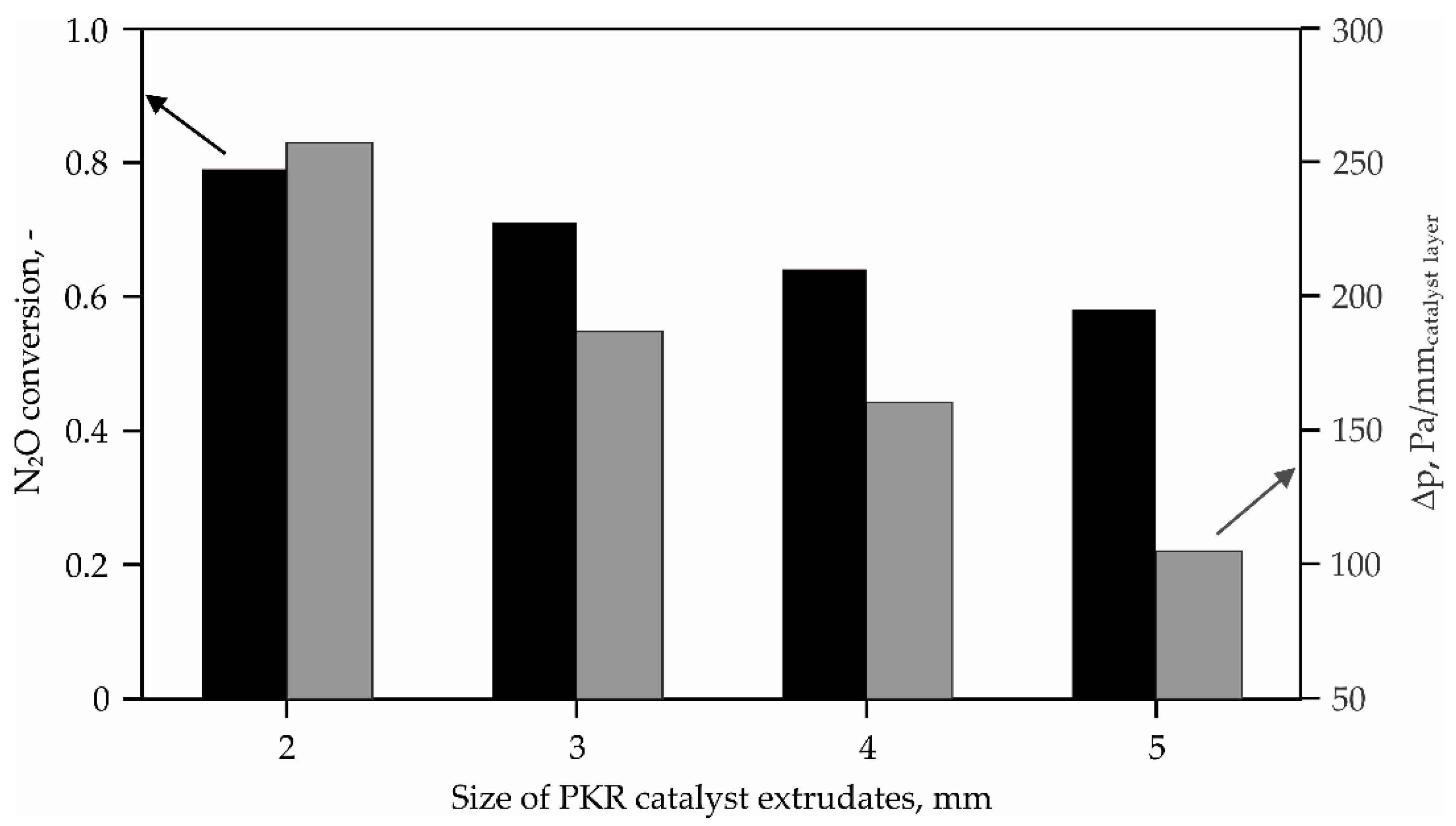
2.1. High-Temperature N2O Decomposition

The proposed catalyst for a high-temperature N2O decomposition is a commercial catalyst (PKR), whose formula and method of manufacture were developed at ŁUKASIEWICZ—New Chemical Syntheses Institute and they were patented [32]. It is a result of years of research, carried out both on a laboratory, pilot and industrial scale.
In Figure 1, the results of the activity tests in a pilot nitric acid plant are presented for PKR catalyst in the form of cylindrical extrudates of various diameters, in the range of 2–5 mm, and a length of 6 ± 2 mm. The catalyst layer was installed in a reactor with an internal diameter of 100 mm, downstream of the Pt-Rh catalytic gauze’s package. Based on the pilot-scale activity tests, the dependence of N2O conversion over the catalyst layer of a fixed height versus the size of the catalyst extrudates (extrudates diameter in the range of dextr. = 2–5 mm) forming the layer, was determined. N2O conversion over PKR catalyst was referred to as a nitrous oxide concentration downstream of Pt-Rh gauze’s package, measured in the reference reactor (as a primary N2O emission). All the measurements were performed for the same operating conditions of ammonia oxidation (TNG = 890 °C, p = 5 bar, VNG = 58 Nm3/h). In addition, the nitrous gases flow resistances across the studied PKR catalyst beds were measured.
Catalysts for a high-temperature N2O decomposition usually have high initial activity, but do not have sufficiently high stability to maintain it throughout the entire operating time. Therefore, except for the high activity, another condition for their implementation in an industrial reactor is their lifetime. It is particularly important for extremely severe operating conditions, i.e., high temperature, reaching about 900 °C and a high water content in the nitrous gases stream CH2O > 15 vol %.
In order to determine the rate of the catalyst aging, the dependence of its activity on the time of its exposure to the real nitrous gas’ stream was tested, under the same operating parameters as prevailing in the industrial plant. The results were related to the activity of the fresh catalyst sample (Figure 2).
In Figure 3, the dependence of N2O concentration in the post-reaction gas (secondary emission) on the nitrous gas temperature and gas flow rate was shown. The presented results indicate a significant influence of the gas flow rate on the secondary emission of nitrous oxide, especially at lower process temperatures. Based on this research, it is possible to select the optimal operating conditions for various forms of the HT-deN2O catalyst and to select its suitable form for a given industrial reactor.

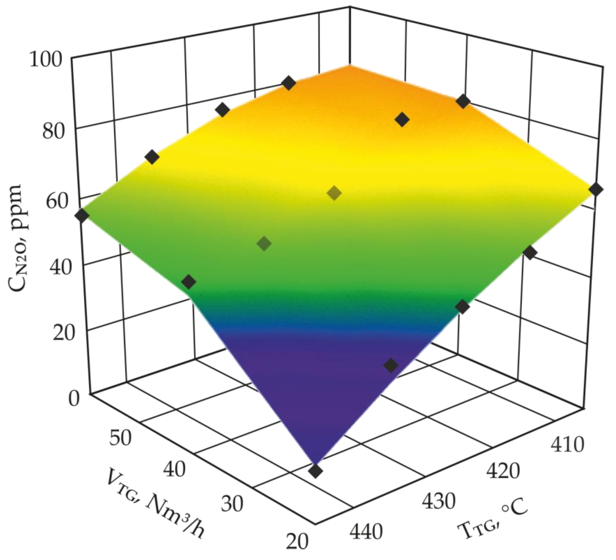
2.2. Low-Temperature N2O Decomposition

As part of ŁUKASIEWICZ-INS cooperation with Jagiellonian University, an original catalyst for a low-temperature N2O decomposition (LT-deN2O) from the tail gas stream was developed (National Center for Research and Development Project No. PBS2/A5/38/2013). It is a supported catalyst, consisting of cobalt-zinc spinel surface-modified with potassium, deposited on α-Al2O3 support in the form of rings (diameter × height = 5 × 2 mm). Catalytic tests carried out under model conditions using the model mixture containing only N2O in N2 confirmed its high activity in the LT-deN2O reaction [38]. However, a key aspect of its industrial implementation is the pilot-scale testing under real process conditions. The developed catalyst was tested in a pilot reactor with an internal diameter of 0.21 m, fed with the tail gas from industrial nitric acid plant. The reactor is connected to a bypassed tail gas stream, between the industrial SCR-deNOx reactor and the expansion turbine.
In Figure 4, the dependence of N2O concentration in the tail gas stream downstream of the LT-deN2O catalyst layer on the tail gas flow rate and tail gas temperature is shown.
Similarly, for PKR catalyst, the stability tests for K/Zn0.4Co2.6O4/α-Al2O3 catalyst were performed. The measured activity of the cobalt catalyst, after various times of its exposure to the tail gas’ stream (up to 7200 h) was compared with the activity of the fresh sample. All activity measurements were performed under the same operating parameters i.e., TTG = 445 °C, p = 10.5 bar, VTG = 40 Nm3/h.
The results shown in Figure 5 indicate that K/Zn0.4Co2.6O4/α-Al2O3 catalyst retains its initial activity for at least 7200 h of its exposition in the tail gas stream. Small differences in N2O conversion may be associated with the variability of the tail gas composition, i.e., differences in the content of NOx, which has a strong inhibitory effect on the deN2O process over a cobalt catalyst [38].

3. Discussion

The results of the tests, performed for both types of catalysts indicate that they are active in the N2O decomposition reaction under the conditions prevailing in the nitric acid plants.
In Figure 6, the N2O conversion curve as a function of the product kgenτ for first-order rate law (Equation (3)) which is fulfilled for any catalyst type is shown.
For a given constant process temperature which specifies the value of the reaction rate constant kgen according to Equation (4), the final N2O conversion (Equation (3)) is determined by the residence time τ. Hence, the use of a sufficiently large volume of the catalyst bed allows for a deep abatement of N2O emission.
For a high-temperature N2O decomposition method, the operating temperature is determined by the conditions of the ammonia oxidation process on Pt-Rh gauzes. If the catalyst is installed in an existing reactor, both the diameter and the height of the catalyst layer are predetermined. Ammonia oxidation reactors have usually diameters from 2 to 6 m, whereas the height of the catalyst bed is 50–300 mm, depending on the reactor design.
So far, an inert bed in the form of Raschig rings (e.g., made of Al2O3) was installed downstream of the Pt-Rh gauze’s package in existing ammonia oxidation reactors. The role of this bed is to stabilize the gas flow throughout the whole cross-section of the reactor. Replacing the layer of the Raschig rings with the deN2O catalyst bed, allows not only to stabilize the gas flow but also to reduce N2O concentration in the nitrous gas’ stream.
As seen in Figure 1, reducing the diameter of the shaped catalyst from 5 mm to 2 mm leads to an increase of N2O conversion from 0.58 to 0.79 and simultaneously to 2.5-fold increase of pressure drop across the catalyst layer.
Usually, when choosing a catalyst, a compromise solution is adopted, taking into account the allowable pressure drop in the ammonia oxidation reactor (which is a significant problem in the case of high-pressure plants), the desired reduction of N2O emission and a free space in the reactor downstream of the catalytic gauze’s package, available for installing on the catalyst layer.
The results shown in Figure 2 indicate that the activity of the PKR catalyst does not decrease after more than a year of its time-on-stream in the typical operating conditions prevailing in an industrial plant. In practice, in many nitric acid plants, PKR catalyst works stably for several years and no significant deviations from its initial activity are observed [4]. The condition is, however, to provide a stable catalyst layer, which is problematic in the case of some ammonia oxidation reactors, due to their construction. The catalyst for HT-deN2O installed downstream of Pt-Rh gauzes works under severe process conditions. In addition, and as a consequence the catalyst may undergo a thermal shrinkage due to high operating temperature, and as a consequence, the catalyst layer is lowered. Although no excessive mechanical pressure on the catalyst bed has been identified (low bed height) and the forces arising from the flow resistances are insignificant, it should be emphasized that the catalyst is usually installed in a catalytic basket resting directly on the heat exchanger pipes or on the supporting structure. During its operation, vibrations occur, which can cause migration of the catalyst bed in the reactor towards its central part. As a result, the phenomenon of a gas bypassing may occur, during its flow through the catalyst layer. This means in practice that the final N2O emission can increase during catalyst operation, although no decrease in catalyst activity over time of its operation was observed.
The operating parameters of ammonia oxidation can also affect the final N2O emission [1]. The results presented in Figure 3, where the concentration of N2O in the post-reaction gas was expressed, take into account the variability of the amount of N2O formed during the ammonia oxidation.
It should also be taken into account that the HT-deN2O method does not contribute to the removal of nitrous oxide, formed at the later stages of nitric acid production. It can be formed in much smaller amounts than at the beginning of the technological line, but in some cases, this problem cannot be ignored. The source of additional nitrous oxide production may be side reactions occurring during the process of NOx removal from the tail gas by SCR with ammonia.
When analyzing Figure 6, it was found that increasing N2O conversion from 0.80 to 0.95 requires increasing the volume of a catalyst bed by 1.875-fold. This is not always possible meet while replacing the reactor with another, as only increasing the abatement of N2O emission is economically unreasonable.
The results of our works that we have carried out show that HT-deN2O is not the only effective solution. N2O decomposition can be also successfully realized by the LT-deN2O method at the end of the technological line of nitric acid production. Due to the milder operating conditions, especially due to lower temperature, no shrinkage of the shaped catalyst is observed. The installation of an additional reactor upstream of the expansion turbine guarantees N2O decomposition from all the stages of nitric acid production. In addition, the process selectivity is not required here.
Presented results (Figure 4 and Figure 5) of the developed catalyst for the LT-deN2O process indicate that it is active under the conditions prevailing in the nitric acid plants and it maintains its initial activity over the long operating time.
The main limitation of the effective use of this catalyst and LT-deN2O method is the necessity to ensure a sufficiently high temperature of the tail gas and sufficiently long residence time in the reactor. If the temperature of the tail gas in the technological line is too low for the effective operation of the catalyst, then this technology cannot be used or it is necessary to heat up the tail gas. The costs of gas heating should be included in the costs of the technology’s implementation. Implementation of the LT-deN2O catalyst requires the installation of an additional apparatus—reactor for N2O decomposition. If it is properly designed, it ensures high final N2O conversion. At the design stage of the LT-deN2O reactor, the size of the catalyst bed should be optimized. The results of the activity tests show that for a given temperature it is possible to select such a residence time that N2O conversion close to one can be obtained. Under industrial conditions, the process of N2O decomposition begins at a temperature of about 400 °C. The only parameter of the tail gas that can affect this process is NOx concentration in the gas stream, downstream of the deNOx catalyst bed. Purification of the tail gas from NOx leads to a higher conversion of nitrous oxide and its lower concentration downstream of the LT-deN2O catalyst bed [37]. When choosing the volume of the catalyst, also the economic aspect should be taken into account. According to the dependence, presented in Figure 6, increasing N2O conversion from, e.g., to 0.99 requires a substantial increase in the amount of the used catalyst.
Analyzing the advantages and limitations of high-and low-temperature methods, it can be concluded that a combination of these both technologies in one nitric acid plant can be a beneficial and attractive solution. The obvious benefit is a high final N2O conversion. Taking into account the high price of CO2-eq emission allowances, maximizing the reduction of nitrous oxide emission can bring tangible economic benefits. The combination of both methods of N2O decomposition allows for minimizing the implementation cost by reducing the catalyst bed volume used in the process (V). The solution is illustrated in the following simulations (Table 1).
Based on the data presented in the experimental part and simulation calculations, the more preferred option seems to be the scenario, in which both technologies of N2O decomposition are involved (Scenario 4–6). This combination ensures a high final nitrous oxide conversion (CN2O at the outlet of the plant below 40 ppm). Only the use of the catalyst layer, which achieves a 0.95 conversion rate of N2O (Scenario 3), would provide comparable results. However, Scenario 3 may not be technically feasible in numerous cases, due to the insufficient free available space in the ammonia oxidation reactor (for high-temperature technology) or the necessity to use a large catalyst bed volume, translating into high investment costs and an excessive increase in the gas flow resistances (for LT-deN2O technology). On the other hand, the use of both technologies in one nitric acid plant gives greater reserve in meeting the emission standards when, for operational reasons (e.g., gas bypassing in the ammonia oxidation reactor), the efficiency of high-temperature technology will be reduced.
Given the persistently high prices of CO2-eq emission allowances it will be economically profitable in the long term, despite the fact that it requires investment outlays, related to the interference in the nitric acid installation, additional reactor construction and purchasing the LT-deN2O catalyst.

4. Materials and Methods

4.1. Manufacturing of the Catalysts on a Large Scale

4.1.1. HT-deN2O Catalyst (PKR)

The mixture of aluminum and iron hydroxides was used as a precursor of the PKR catalyst and was prepared by coprecipitation of the corresponding iron (III) and aluminum salts in a water solution. The resulting suspension was filtered off, washed with distilled water and dried in air atmosphere. The obtained powder was ground, mixed with batch water to obtain a plastic mass and shaped by an extrusion into extrudates with diameters of 2–5 mm and a length of 4–8 mm. The shaped catalyst precursor was dried and calcined at a temperature of 400 °C in air atmosphere. The average final catalyst composition is the following: 75 wt % Fe2O3 and 25 wt % Al2O3. The PKR catalyst is produced on an industrial scale at Łukasiewicz Research Network—New Chemical Syntheses Institute and is the subject of patent No. PL 207,666 B1 [32]. The physical characterization of the PKR catalyst is included elsewhere [39,40].

4.1.2. LT-deN2O Catalyst (K/Zn0.4Co2.6O4/α-Al2O3)

The catalyst support was prepared by mixing aluminum hydroxide with batch water and then shaped into Raschig rings with dimensions: diameter × height = 5 × 2 mm. The shaped support was dried at a temperature of 105 °C and calcined in air atmosphere at 1400 °C for 4 h. Then, α-Al2O3 support was coimpregnated with a solution of cobalt, zinc and potassium nitrates. The precursor of K/Zn0.4Co2.6O4/α-Al2O3 catalyst was dried at a temperature of 105 °C and calcined for 4 h at 450 °C in air atmosphere. The concentration of Co, Zn and K salts, as well as the multiplicity of impregnation were selected in such a way as to obtain the final concentration of the active phase in the supported catalyst at a level of ≤20 wt %, based on the total mass of the catalyst. The potassium content in the supported catalyst was about 5 atoms per 1 nm2 of the support’s surface. The catalyst is the subject of Patent Application No. EP 16,000,547 [41]. The physical characterization of the catalyst is included elsewhere [42,43].

4.2. Activity Tests for PKR Catalyst in a Pilot Nitric Acid Plant

The activity of the PKR catalyst for a high-temperature N2O decomposition was tested in a pilot nitric acid plant, which was presented in previous work [1,44]. The plant consists of the analogical units as existing in industrial plants, i.e., ammonia–air mixture preparation, ammonia oxidation, heat exchange, nitric oxide oxygenation and absorption unit. Ammonia oxidation unit consists of identical, parallel working reactors, in which standard knitted gauzes of a specific weight of 600 g/m2, made of 0.076 mm wire of platinum alloy with 10% rhodium addition, were used as an ammonia oxidation catalyst. N2O concentration, measured in the reactor, containing only the catalytic gauzes, was taken as the primary N2O emission, resulting from the side reaction of ammonia oxidation to N2O. The PKR catalyst in the form of extrudates with diameters of 2, 3, 4 and 5 mm was installed in the ammonia oxidation reactor downstream of the catalytic gauze’s package in the catalytic basket with a diameter of 0.1 m. The mass of the catalyst, installed in the reactor, was about 0.6 kg for all the tested samples.
Activity tests were conducted at the operating parameters, corresponding to the operating conditions of a medium pressure nitric acid plant: p = 5.0 bar, TNG = 890 °C, VNG = 58 Nm3/h and NH3 concentration in NH3-air mixture was about 10.7 vol %. On the basis of N2O concentration, measured in the reference reactor and in the reactor containing PKR catalyst, N2O conversion over the catalyst layer was determined. For a chosen PKR catalyst sample (d = 2 mm), the influence of operating temperature and gas flow rate on N2O concentration at the outlet of the reactor were studied. The parameters were changed in the range of: TNG = 870–910 °C, VNG = 44–68 Nm3/h. All the measurements were conducted at a pressure of p = 45 bar.
The N2O concentration in nitrous gas was determined by a gas chromatography method using a discharge ionization detector (DID).

4.3. Activity Test of the LT-deN2O Catalyst

The activity tests of the LT-deN2O catalyst were conducted in the fixed bed reactor of an internal diameter of 0.21 m, connected to the bypassed tail gas from industrial nitric acid plant. A catalyst layer in the form of single-hole Raschig rings was installed in the reactor (mass of the catalyst: 10.2 kg). The activity tests were carried out at a temperature of TTG = 405–445 °C, the inlet pressure of p = 10.5 bar and at a tail gas flow rate varying in the range of VTG = 20–60 Nm3/h. The average composition of the gas stream at the inlet of the LT-deN2O reactor was as follows: 80 ppm N2O, 65 ppm NOx, 2.4% obj. O2, H2O and N2. The N2O concentration in the tail gas stream at the inlet and the outlet of the reactor was determined by FTIR method using an on-line analyzer.

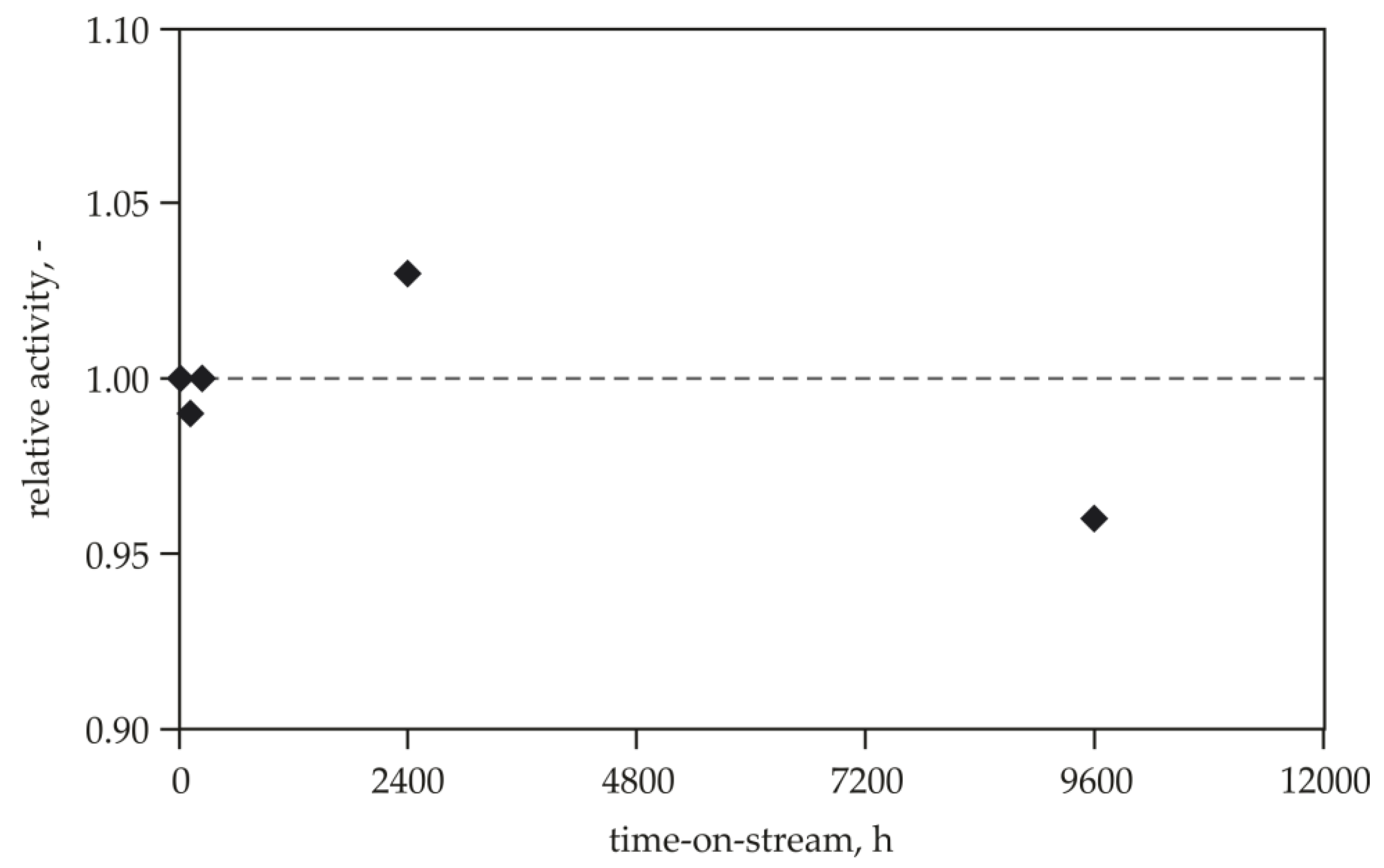
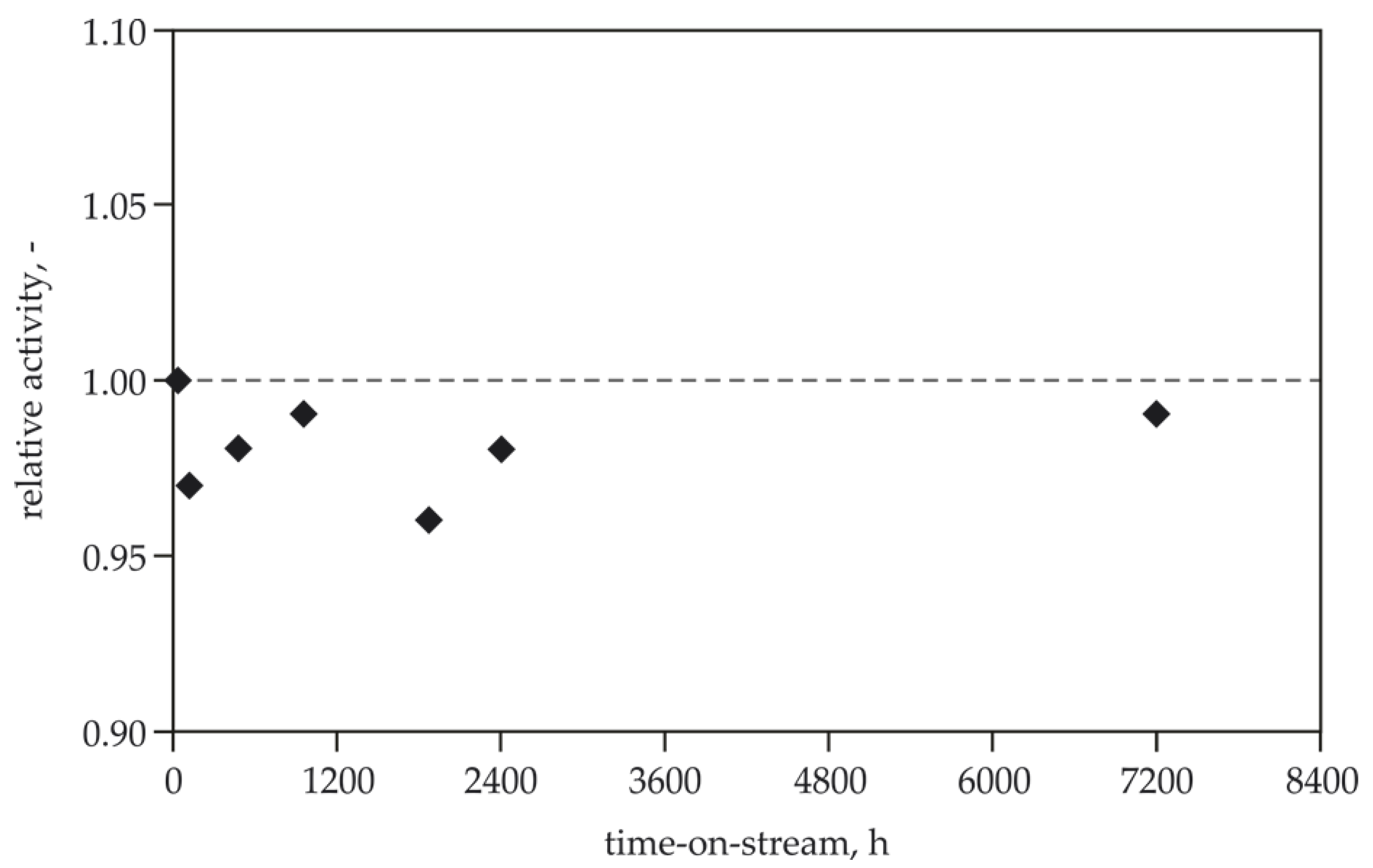
4.4. Stability Tests of the HT-deN2O and LT-deN2O Catalysts

The stability tests of both catalysts (for HT-deN2O and LT-deN2O) were carried out on the pilot scale. The catalyst’s samples were placed into a real reaction gas stream. For the selected catalyst sample (independently for both catalysts) after appropriate time-on-stream, the N2O conversion was determined. All results were related to the activity of the fresh catalyst sample. Conditions of the tests were the following: TNG = 890 °C, p = 5.0 bar VNG = 58 Nm3/h and TTG = 445 °C, p = 10.5 bar, VTG = 40 Nm3/h for the HT-deN2O and LT-deN2O catalysts, respectively. Analytical methods were identical as in activity tests.

5. Conclusions

The results of the activity tests, carried out under real process conditions for the catalysts developed at INS indicate that the use of both types of catalysts, after meeting the relevant conditions (process temperature, residence time), allow for the effective N2O decomposition. For the HT-deN2O method, the catalyst is usually installed in existing reactors and both the diameter and the height of the catalyst bed are predetermined. In this case, an increase of N2O conversion is possible by reducing the diameter of the shaped catalyst. However, it leads to the simultaneous increase of pressure drop across the catalyst layer. The presented results of the developed catalyst for the LT-deN2O process indicate it is active under the conditions prevailing in the nitric acid plants and it maintains its initial activity over the operating time. For this catalyst, designing of the reactor with sufficiently large dimensions is possible, however when we choose the catalyst volume, the economic aspect should also be taken into account.
The combined use of high-and low-temperature methods leads to a deep purification of the process gas of N2O (below 40 ppm), despite the technological constraints. The implementation of these deN2O technologies according to Scenarios 1–6, depends on the individual characteristics of the nitric acid plant, especially: ammonia oxidation parameters, the construction of ammonia oxidation reactor and tail gas temperature upstream of the expansion turbine. The selection of the optimal technology must be considered individually for the particular nitric acid plant.
Assuming the long lifetime of the catalyst for a low-temperature N2O decomposition, despite a quite high investment costs, it can be concluded that the combination of both deN2O technologies can be an economically attractive solution.

Author Contributions

Conceptualization, M.I. and M.W.; methodology, M.I. and B.M.; investigations, M.I., B.M., M.R., and J.R.; writing—original draft preparation, M.I. and M.R.; writing—review and editing, B.M., J.R. M.W. All authors have read and agreed to the published version of the manuscript.

Funding

Part of this research was funded by NCBiR (National Centre for Research and Development) Project No. PBS2/A5/38/2013.

Conflicts of Interest

The authors declare no conflict of interest.

Abbreviations

CN2Oconcentration of N2O (mol·m−3 or ppm)
dextextrudate diameter (mm)
E0activation energy (J/mol)
kgengeneral reaction rate constant, first-order rate law (s−1)
k0Arrhenius pre-exponential factor (s−1)
poperating pressure (barg)
Rgas constant (J·mol−1·K−1)
rcatreaction rate per unit weight of catalyst (mol·kg−1·s−1)
XN2Omolar fraction of N2O (−)
Ttemperature in Arrhenius equation (K)
TNGnitrous gas temperature (°C)
TTGtail gas temperature (°C)
Vcatalyst bed volume (m3)
VNGnitrous gases flow rate (Nm3·h−1)
VTGtail gas flow rate (Nm3·h−1)
XN2ON2O conversion
Greek symbols:
πpressure drop (Pa/mmcatalyst layer)
τresidence time (s)

References

  1. Inger, M.; Dobrzyńska-Inger, A.; Rajewski, J.; Wilk, M. Optimization of ammonia oxidation using Response Surface Methodology. Catalysts 2019, 9, 249. [Google Scholar] [CrossRef] [Green Version]
  2. Pérez-Ramírez, J.; Kapteijn, F.; Schöffel, K.; Moulijn, J.A. Formation and control of N2O in nitric acid production: Where do we stand today? Appl. Catal. B Environ. 2003, 44, 117–151. [Google Scholar] [CrossRef]
  3. Isupova, L.A.; Ivanova, Y.A. Removal of nitrous oxide in nitric acid production. Kinet. Catal. 2019, 60, 744–760. [Google Scholar] [CrossRef]
  4. Wilk, M.; Inger, M.; Kruk, J.; Gołębiowski, A.; Jancewicz, R.; Szczepaniak, B. Obniżenie emisji podtlenku azotu z instalacji kwasu azotowego. Przem. Chem. 2009, 88, 730–733. [Google Scholar]
  5. Stefanova, M.; Chuturkova, R. Technical engineering for catalytic reduction of nitrous oxide emissions. J. Eng. Technol. 2015, 3, 89–94. [Google Scholar] [CrossRef] [Green Version]
  6. Konsolakis, M.I. Recent advances on nitrous oxide (N2O) decomposition over non-noble-metal oxide catalysts: Catalytic performance, mechanistic considerations, and surface chemistry aspects. ACS Catal. 2015, 5, 6397–6421. [Google Scholar] [CrossRef]
  7. Centi, G.; Perathoner, S. Reduction of greenhouse gas emissions by catalytic processes. In Handbook of Climate Change Mitigation and Adaptation, 2nd ed.; Springer: Cham, Switzerland, 2016; Volume 4, pp. 2827–2880. [Google Scholar]
  8. Kim, M.-J.; Lee, S.J.; Ryu, I.-S.; Jeon, M.-W.; Moon, S.-H.; Roh, H.-S.; Jeon, S. Catalytic decomposition of N2O over cobalt based spinel oxides: The role of additives. Mol. Catal. 2017, 442, 202–207. [Google Scholar] [CrossRef]
  9. Granger, P.; Dacquin, J.-P.; Dujardin, C. Catalytic abatement of N2O from stationary sources. In Perovskites and Related Mixed Oxides: Concepts and Applications; Wiley-VCH Verlag GmbH & Co. KGaA: Weinheim, Germany, 2015; pp. 611–630. [Google Scholar]
  10. Schoonheydt, R.; Vanelderen, P.; Sels, B. Direct catalytic decomposition of N2O over Cu-and Fe-zeolites. In New and Future Develelopments in Catalysis: Catalysis for Remediation and Environmental Concerns; Elsevier: Amsterdam, The Netherlands, 2013; pp. 399–419. [Google Scholar]
  11. Ohnishi, C.; Asano, K.; Iwamoto, S.; Chikama, K.; Inoue, M. Preparation of Co3O4 catalysts for direct decomposition of nitrous oxide under industrial conditions. Stud. Surf. Sci. Catal. 2006, 162, 737–744. [Google Scholar]
  12. Wójcik, S.; Grzybek, G.; Stelmachowski, P.; Sojka, Z.; Kotarba, A. Bulk, surface and interface promotion of Co3O4 for the low-temperature N2O decomposition catalysis. Catalysts 2020, 10, 41. [Google Scholar] [CrossRef] [Green Version]
  13. Zhao, T.; Li, Y.; Gao, Q.; Liu, Z.; Xu, X. Potassium promoted Y2O3-Co3O4 catalysts for N2O decomposition. Catal. Commun. 2020, 137, 105948. [Google Scholar] [CrossRef]
  14. Richards, N.; Carter, J.H.; Nowicka, E.; Parker, L.A.; Pattisson, S.; He, Q.; Dummer, N.F.; Golunski, S.; Hutchings, G.J. Structure-sensitivity of alumina supported palladium catalysts for N2O decomposition. Appl. Catal. B Environ. 2020, 264, 118501. [Google Scholar] [CrossRef]
  15. Hoang Ho, P.; Jabłońska, M.; Palkovits, R.; Rodriguea-Castellon, E.; Ospitali, F.; Formasari, G.; Vaccari, A.; Benito, P. N2O catalytic decomposition on electrodeposited Rh-based open-cell metallic foams. Chem. Eng. J. 2020, 379, 122259. [Google Scholar]
  16. Zhao, T.; Gao, Q.; Liao, W.; Xu, X. Effect of Nd-incorporation and K-modification on catalytic performance of Co3O4 for N2O decomposition. J. Fuel Chem. Technol. 2019, 47, 1120–1128. [Google Scholar] [CrossRef]
  17. Basahal, S.N.; Mokhtar, M.; Ali, T.T.; Narasimharao, K. Porous Fe2O3-ZrO2 and NiO-ZrO2 nanocomposites for catalytic N2O decomposition. Catal. Today 2020, 348, 166–176. [Google Scholar] [CrossRef]
  18. Pietrogiacomi, D.; Campa, M.C.; Carbone, L.R.; Occhiuzzi, M. N2O decomposition and reduction on Co-MOR, Fe-MOR and Ni-MOR catalysts: In situ UV–vis DRS and operando FTIR investigation. An insight on the reaction pathways. Appl. Catal. B Environ. 2019, 240, 19–29. [Google Scholar] [CrossRef]
  19. Bernauer, M.; Bernauer, B.; Sádovská, G.; Sobalík, Z. High-temperature decomposition of N2O from the HNO3 production: Process feasibility using a structured catalyst. Chem. Eng. Sci. 2020, 220, 115624. [Google Scholar] [CrossRef]
  20. Galejová, K.; Obalová, L.; Jirátová, K.; Pacultová, K.; Kovanda, F. N2O catalytic decomposition—Effect of pelleting pressure on activity of Co-Zn-Al mixed oxide catalyst. Chem. Pap. 2009, 63, 172–179. [Google Scholar] [CrossRef]
  21. Obalová, L.; Jirátová, K.; Karásková, K.; Chromčáková, Ž. N2O catalytic decomposition—From laboratory experiment to industry reactor. Catal. Tod. 2012, 191, 116–120. [Google Scholar] [CrossRef] [Green Version]
  22. Inger, M.; Wilk, M.; Saramok, M.; Grzybek, G.; Grodzka, A.; Stelmachowski, P.; Makowski, W.; Kotarba, A.; Sojka, Z. Cobalt spinel catalyst for N2O abatement in the pilot plant operation—Long-term activity and stability in tail gases. Ind. Eng. Chem. Res. 2014, 53, 10335–10342. [Google Scholar] [CrossRef]
  23. Obalová, L.; Klegova, A.; Matĕjová, L.; Pacultová, K.; Fridrichová, D. Must the best laboratory prepared catalyst also be the best in an operational application. Catalysts 2019, 9, 160. [Google Scholar]
  24. Melian-Cabrera, I.; Espinosa, S.; Mentruit, C.; Murray, B.; Falco, L.; Socci, J.; Kapteijn, F.; Moulijn, J.A. Overcoming the engineering constraints for scaling-up the state-of-the-art catalyst for tail-gas N2O decomposition. Ind. Eng. Chem. Res. 2018, 57, 939–945. [Google Scholar] [CrossRef] [Green Version]
  25. Axon, S.; Coupland, D.; Horner, B.; Ridland, J.; Wishart, I.; Johnson Matthey PLC. Improved Catalyst Charge Design. Patent WO 2004/096702 A2, 11 November 2004. [Google Scholar]
  26. Schumacher, V.; Bürger, G.; Fetzer, T.; Baier, M.; Hesse, M.; BASF. Method for the Catalytic Decomposition of N2O. Patent WO 99/55621, 4 November 1999. [Google Scholar]
  27. Baier, M.; Fetzer, T.; Hofstadt, O.; Hesse, M.; Buerger, G.; Harth, K.; Schumacher, V.; Wistuba, H.; Otto, B.; BASF. High-Temperature Stabile Catalysts for Decomposing N2O. Patent WO 0023176, 27 April 2000. [Google Scholar]
  28. Nirisen, O.; Schoeffel, K.; Waller, D.; Oevreboe, D.; Norsk Hydro, A.S. Catalyst for Decomposing Nitrous Oxide and Method for Performing Processes Comprising Formation of Nitrous Oxide. Patent WO/2002/002230, 10 January 2002. [Google Scholar]
  29. Neveu, B.; Hamon, C.; Grande Paroisse, S.A. Method for Reducing Nitrous Oxide in Gases and Corresponding Catalysts. Patent WO1999/64139 A1, 16 December 1999. [Google Scholar]
  30. Jantsh, U.; Lund, J.; Kraus, M.; Gorywoda, M.; Heraeus GMBH. Catalyst for Decomposition of Nitrous Oxide under Conditions of Ostwald Process, Comprises Carrier Material, and Coating of Rhodium, Rhodium Oxide, or Palladium-Rhodium Alloy. Patent DE 102004024026 A1, 29 September 2005. [Google Scholar]
  31. Wilk, M.; Kruk, J.; Gołębiowski, A.; Prokop, U.; Śpiewak, Z.; Saran, H.; Instytut Nawozów Sztucznych. Sposób Wytwarzania Katalizatora do Rozkładu Podtlenku Azotu, Zwłaszcza w Gazach z Instalacji Kwasu Azotowego. Patent PL206340, 19 December 2005. [Google Scholar]
  32. Wilk, M.; Kruk, J.; Gołębiowski, A.; Instytut Nawozów Sztucznych. Katalizator do Rozkładu Podtlenku Azotu, Zwłaszcza w Gazach z Instalacji Kwasu Azotowego. Patent PL207666, 19 December 2005. [Google Scholar]
  33. Burckhardt, W.; Seifert, F.; Voigt, M.; Winterstein, G.; Hermsdorfer Institut für Technische Keramik. Ceramic Catalyst for Selectively Decomposing N2O and a Method for the Production Thereof. Patent WO2000/13789, 27 July 2000. [Google Scholar]
  34. Schwefer, M.; Seifert, R.; Fuchs, J.; Ruthardt, K.; Groves, M.; Thyssenkrupp Industrial Solutions AG. Method for Removing N2O and NOx From the Nitric Acid Production Process, and an Installation Suitable for Same. Patent US20170334722, 23 November 2017. [Google Scholar]
  35. BASF Page. Available online: https://catalysts.basf.com/literature-library/stationary-emissions-catalysts/nitrous-oxide-destruction (accessed on 30 July 2020).
  36. Clariant Page. Available online: https://www.clariant.com/de/Solutions/Products/2019/07/22/08/03/EnviCat-N2O (accessed on 30 July 2020).
  37. Burghardt, A.; Bartelmus, G. Inżynieria Reaktorów Chemicznych; PWN: Warszawa, Poland, 2001. [Google Scholar]
  38. Inger, M.; Rajewski, J.; Ruszak, M.; Wilk, M. The influence of NOx presence on the catalytic N2O decomposition over the supported double-promoted cobalt spinel catalyst. Chem. Pap. 2019, 73, 1979–1986. [Google Scholar] [CrossRef] [Green Version]
  39. Giecko, G.; Borowiecki, T.; Gac, W.; Kruk, J. Fe2O3/Al2O3 catalysts for N2O decomposition in the nitric acid industry. Catal. Tod. 2008, 137, 403–409. [Google Scholar] [CrossRef]
  40. Kruk, J.; Stołecki, K.; Michalska, K.; Konkol, M.; Kowalik, P. The influence of modifiers on the activity of Fe2O3 catalyst for high temperature N2O decomposition (HT-deN2O). Catal. Tod. 2012, 191, 125–128. [Google Scholar] [CrossRef]
  41. Wilk, M.; Inger, M.; Ruszak, M.; Saramok, M.; Kowalik, P.; Antoniak-Jurak, K.; Sojka, Z.; Kotarba, A.; Grzybek, G.; Stelmachowski, P.; et al. Supported Co-Zn Spinel Catalyst for the Abatement of Nitrogen(I) Oxide Emissions Especially from Nitric Acid Plants and a Method for Its Manufacture. Patent EP 16000547, 3 March 2016. [Google Scholar]
  42. Grzybek, G.; Wójcik, S.; Legutko, P.; Gryboś, J.; Indyka, P.; Leszczyński, B.; Kotarba, A.; Sojka, Z. Thermal stability and repartition of potassium promoter between the support and active phase in the K-Co2.6Zn0.4O4/α-Al2O3 catalyst for N2O decomposition: Crucial role of activation temperature on catalytic performance. Appl. Catal. B Environ. 2017, 205, 597–604. [Google Scholar] [CrossRef]
  43. Ciura, K.; Grzybek, G.; Wójcik, S.; Indyka, P.; Kotarba, A.; Sojka, Z. Optimization of cesium and potassium promoter loading in alkali-doped Zn 0.4 Co2.6 O4/Al2 O3 catalysts for N2O abatement. React. Kinet. Mech. Catal. 2017, 121, 645–655. [Google Scholar] [CrossRef] [Green Version]
  44. Gołębiowski, A.; Kruk, J.; Wilk, M. Katalizator do wysokotemperaturowego rozkładu tlenku diazotu. Przem. Chem. 2006, 85, 709–711. [Google Scholar]
Figure 1. The dependence of N2O conversion and pressure drop across the PKR catalyst layer (Δp) on the size of the catalyst extrudes forming the layer. Test parameters: TNG = 890 °C, p = 5 bar, VNG = 58 Nm3/h.
Catalysts 10 00987 g001
Figure 2. Long-term stability test of the PKR catalyst. Test parameters: TNG = 890 °C, p = 5 bar, VNG = 58 Nm3/h.
Catalysts 10 00987 g002
Figure 3. The dependence of N2O concentration in the nitrous gas downstream of the PKR catalyst layer on the nitrous gas temperature and nitrous gas flow rate.
Catalysts 10 00987 g003
Figure 4. The dependence of N2O concentration in the tail gas stream downstream of the LT-deN2O catalyst layer on the tail gas temperature and tail gas flow rate. N2O concentration in tail gas at the inlet equals 80 ppm.
Catalysts 10 00987 g004
Figure 5. Long-term stability test of K/Zn0.4Co2.6O4/α-Al2O3 catalyst. Test parameters: TNG = 445 °C, p = 10.5 bar, VNG = 40 Nm3/h.
Catalysts 10 00987 g005
Figure 6. The dependence of N2O conversion on the product of a reaction rate constant and residence time according to first-order rate law (Equation (3)).
Catalysts 10 00987 g006
Table 1. The comparison of nitrous oxide emission, expressed as N2O concentration at the end of technological line (in the chimney) for combination of different deN2O variants. Assumed primary N2O concentration in nitrous gas after ammonia oxidation reaction zone equals to 1000 ppm.
Scenario 1Scenario 2Scenario 3Scenario 4Scenario 5Scenario 6
XN2O for HT-deN2O0.80.90.950.80.80.9
XN2O for LT-deN2O 0.80.90.9
Vcat for HT-deN2OV1.43 V1.875 VVV1.43 V
Vcat for LT-deN2OV1.43 V1.43 V
CN2O outlet, ppm20010050402010

