Article

Revealing the Effect of Nickel Particle Size on Carbon Formation Type in the Methane Decomposition Reaction

State Key Laboratory of Heavy Oil Processing, China University of Petroleum, Qingdao 266580, China
*
Author to whom correspondence should be addressed.
Catalysts 2020, 10(8), 890; https://doi.org/10.3390/catal10080890
Submission received: 16 July 2020 / Revised: 3 August 2020 / Accepted: 5 August 2020 / Published: 6 August 2020

Abstract

:
Carbon species deposition is recognized as the primary cause of catalyst deactivation for hydrocarbon cracking and reforming reactions. Exploring the formation mechanism and influencing factors for carbon deposits is crucial for the design of rational catalysts. In this work, a series of NixMgyAl-800 catalysts with nickel particles of varying mean sizes between 13.2 and 25.4 nm were obtained by co-precipitation method. These catalysts showed different deactivation behaviors in the catalytic decomposition of methane (CDM) reaction and the deactivation rate of catalysts increased with the decrease in nickel particle size. Employing TG-MS and TEM characterizations, we found that carbon nanotubes which could keep catalyst activity were more prone to form on large nickel particles, while encapsulated carbon species that led to deactivation were inclined to deposit on small particles. Supported by DFT calculations, we proposed the insufficient supply of carbon atoms and rapid nucleation of carbon precursors caused by the lesser terrace/step ratio on smaller nickel particles, compared with large particles, inhibit the formation of carbon nanotube, leading to the formation of encapsulated carbon species. The findings in this work may provide guidance for the rational design of nickel-based catalysts for CDM and other methane conversion reactions.

Graphical Abstract

1. Introduction

Nowadays, in order to solve the problems of energy shortage, increasing environmental pollution and energy demand, the development of new and renewable energy has become the primary tasks facing humanity [1]. According to Richter et al., in the situation of current global energy structure, the world’s demand for primary energy will meet an increase of 55% by the year of 2030 compared to that of 2005, accompanied by a 55% increase in carbon dioxide (CO2) emissions [2]. As a clean, safe, efficient, and renewable energy source, hydrogen (H2) is one of the most economical and effective alternative energy sources for human beings to get rid of their dependence on fossil energy resources [3]. Although it has been industrialized for quite a long time, the steam methane reforming (SMR) process still cannot avoid the shortcomings of high energy consumption and high CO2 emissions [4]. The catalytic decomposition of the methane (CDM) process directly decomposes methane into hydrogen and carbon species under mild endothermic conditions, and is regarded as an alternative process for environmentally benign H2 production. The reaction equation is depicted in Equation (1). Although the prepared hydrogen may be mixed by a small amount of methane, it can be utilized directly in consideration of the tolerance of downstream processes to trace CO2. Besides this, the applications of produced carbon are diverse, further improving the economics of this process [5].
C H 4 C   ( s ) + 2 H 2   ( g )     H r 0 = + 74.6   ( k J / m o l )
Through thermodynamic analysis of the reaction, the temperature for the complete conversion of methane is nearly 1100 °C [6]. Hence, the selection of suitable catalysts is crucial for CDM process. In catalyst research, the nickel-based catalyst has become the most promising candidate because of its high catalytic activity and low price [7,8]. However, the industrial application of nickel-based catalysts is limited by the disadvantages of fast deactivation. Many studies devoted to revealing the deactivation mechanism of nickel-based catalysts indicated that sintering, carbon deposition, poisoning, and mechanical degradation are the main forms of deactivation [9,10,11]. The occurrence of sintering and mechanical degradation can be effectively reduced by optimizing the catalysts’ preparation method, and poisoning can be prohibited by the purification of feed. However, carbon deposits cannot be avoided due to the fact that carbon is one of the doomed products of CDM reaction. Therefore, it is of great theoretical and practical significance to investigate the deactivation mechanism of carbon deposition.
As described in a widely accepted reaction process, methane molecules undergo a cracking reaction on the surface of nickel particles, with the generated hydrogen atoms combining to generate hydrogen molecules. At the same time, the generated carbon atoms diffuse to the metal-support interface and accumulate to form carbon species [6]. The widely reported types of carbon deposits include amorphous carbon and structured graphite-like carbons, such as carbon nanotubes (CNTs) and carbon nano-onions. Once the nickel particles are detached from the support by the formed carbon, CNTs are more likely to form [12,13]. Since the nickel particles locate on the tip of CNTs and keep the active surface exposed, deactivation will not occur until the generated CNTs are crosslinking with each other or the reactor is blocked by excessive production. On the contrary, the encapsulated amorphous carbon is more likely to deactivate by pore blocking or complete encapsulation of metal’s active surface [14]. Much of the literature has revealed the factors of the influence of carbon formation type in CDM reaction, such as the catalyst, reaction condition, feed composition, and fluid field. For example, increasing hydrogen partial pressure or decreasing methane flow rate could lower the encapsulation carbon formation rate, while increasing temperature promoted encapsulation carbon formation [15,16]. Metal–support interaction (MSI), which can be regulated by catalyst composition, will affect the formation of carbon deposits by restricting the mobility of metal particles. It has been found that weak interaction resulted in the tip-growth mode of CNTs, while the strong MSI led to the formation of the base-growth mode of CNTs or encapsulated carbon [17]. Besides this, it has been found that the particle size of metal particles is also a vital factor affecting carbon formation in the methane conversion reaction. Kim et al. [18] observed that the formation of filamentous carbon in dry reforming of methane reaction was significantly affected by the metal particle size and proceeded mostly in metal particles larger than 7 nm. Chen et al. [19] found that a catalyst with small nickel particles deactivated fast when synthesizing carbon nanofibers and obtained a low yield of carbon nanofibers. The nickel particles with a diameter of 34 nm processed the optimum growth rate and yield of nanofibers. Ermakova et al. obtained a similar conclusion to Chen’s results. They observed that the maximum yield of carbon produced by methane decomposition was at the nickel particle size of 20–60 nm [20]. In these works, the authors took the generation of carbon nanotube as the starting point, thus ignoring the discussion on the variation in the hydrogen formation rate during the CDM reaction, and lacked detailed analysis of other carbon deposition types. With the deep understanding of the mechanism of the CDM reaction in recent years, the descriptions of the formation of carbon deposits in these works seems to be insufficient. Given such complexities, further analyses of the effect of metal particle size on the carbon formation in the CDM reaction are urgently needed to guide the design of rational catalysts.
Layered double hydroxides (LDHs), also known as hydrotalcite, are composed of positively charged cationic laminates and interlayer filled anions. The high dispersion of the metal cations in the laminates of LDHs and the alignment of the interlayer anions make the LDHs form a defective structure after calcination and reduction, which greatly improves the catalytic activity of the LDH-based materials. At the same time, the derived strong metal–support interaction from the calcination process prevents the agglomeration of active metals, thus improving catalyst stability. To date, researchers have carried out tremendous works in the preparation of catalysts for methane-cracking or methane-reforming reactions, utilizing hydrotalcite as a precursor [21,22,23,24]. Among these studies, Ni-Mg-Al ternary hydrotalcite was more suitable for methane conversion reactions. In the present study, a series of NiMgAl catalysts with different nickel particle sizes were prepared by the co-precipitation method, and their performances for CDM reaction were tested under the same reaction condition. The catalysts were characterized before reaction to elucidate how the Mg/Al ratio influences the size of the reduced nickel particles. These catalysts were evidenced to have different deactivation rates during the reaction and detailed characterizations were performed to investigate the causes of different deactivation behaviors. The relationship between metal particle size and carbon formation is revealed. With the aid of density functional theory calculations, the mechanism of carbon formation on nickel particles of different sizes is proposed.

2. Results and Discussion

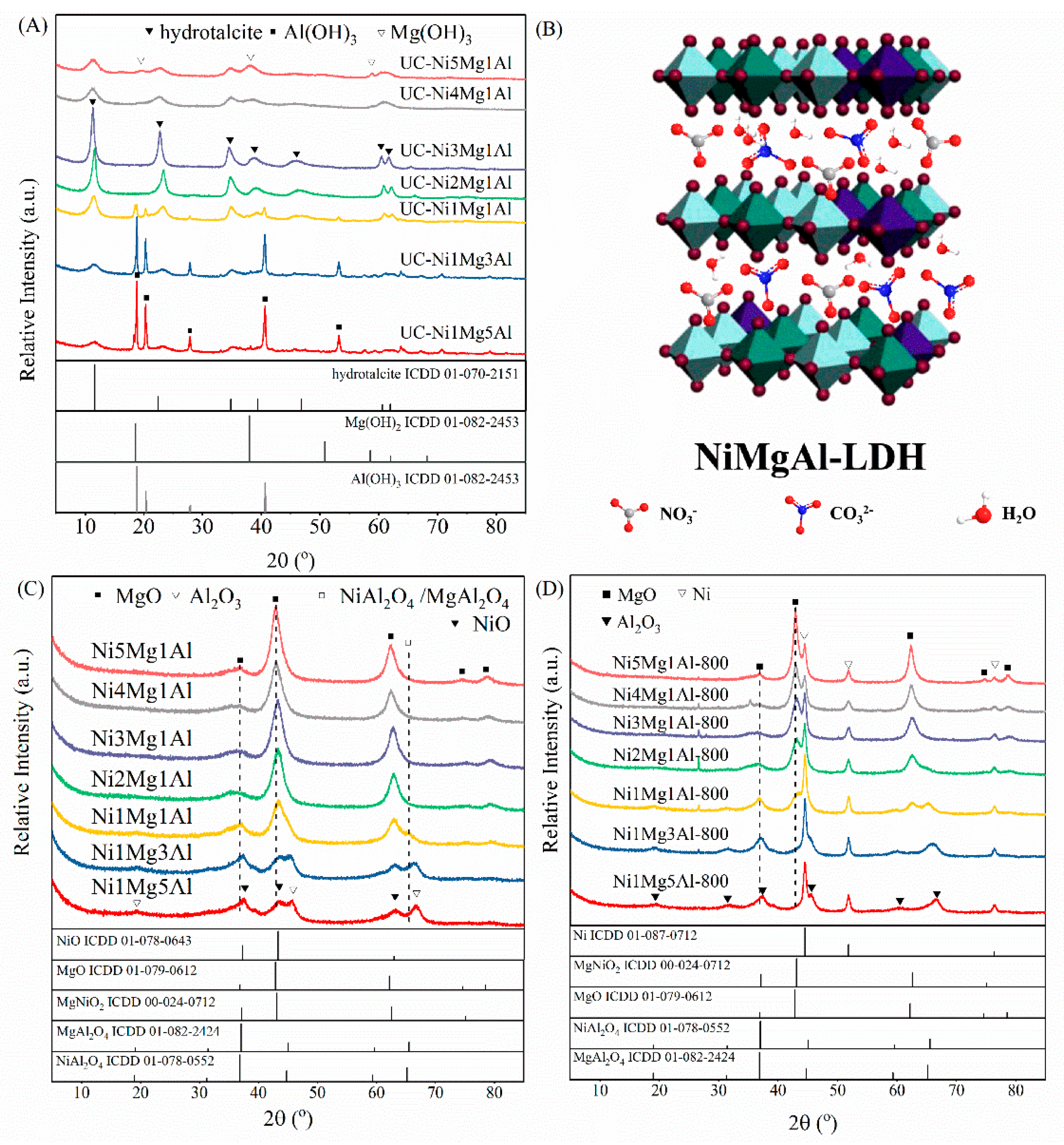
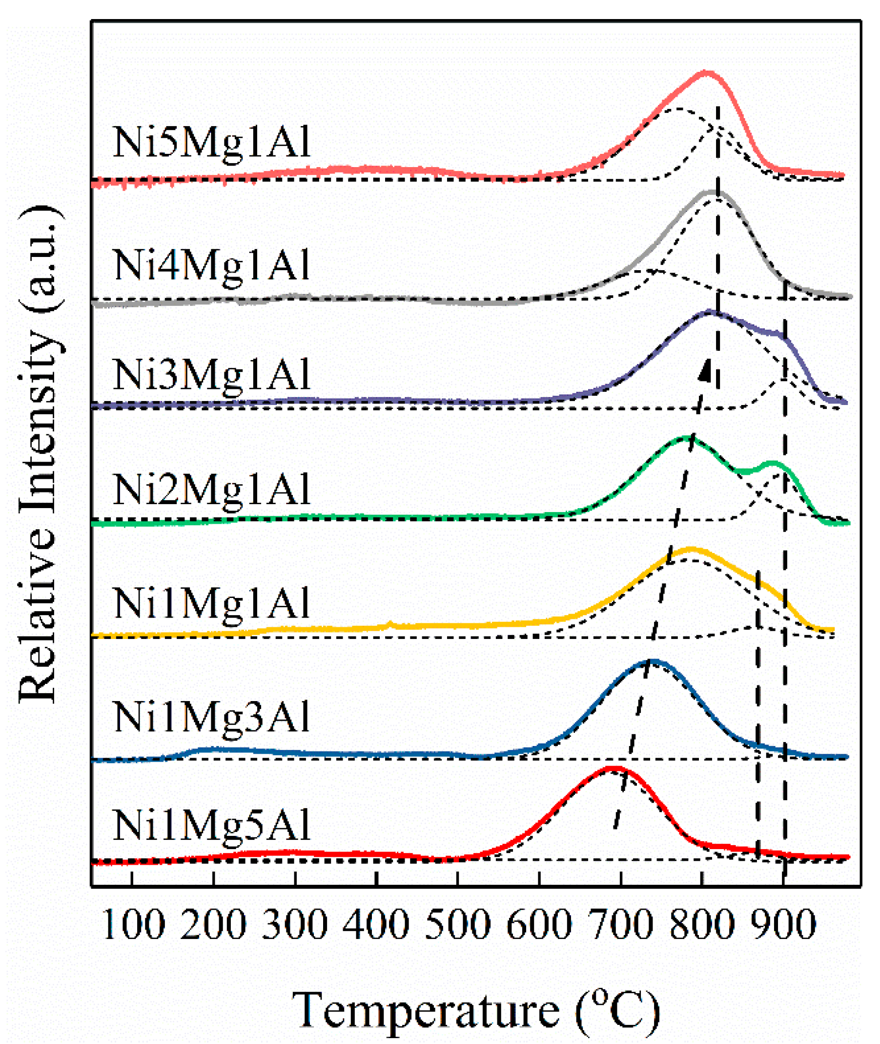
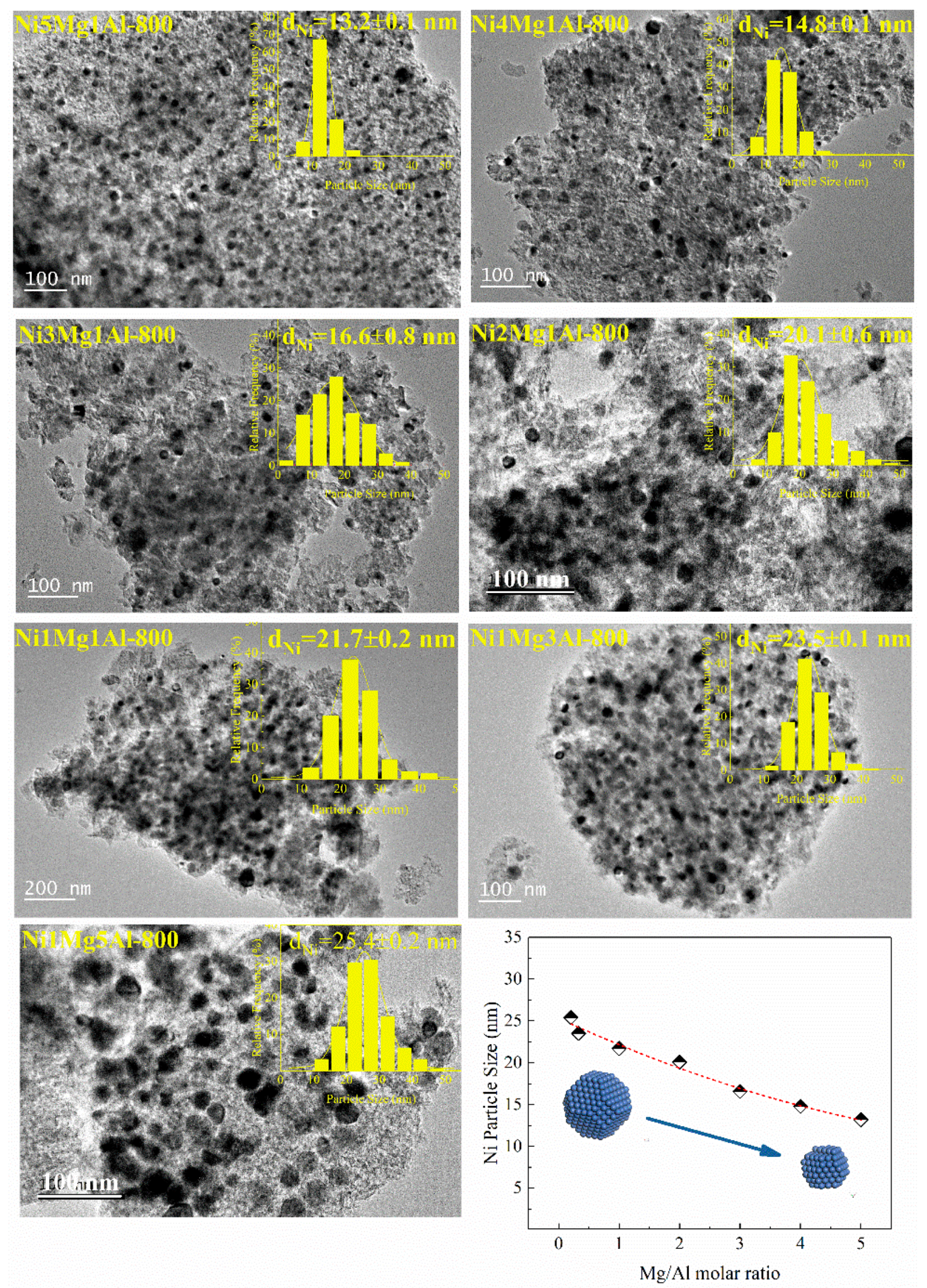
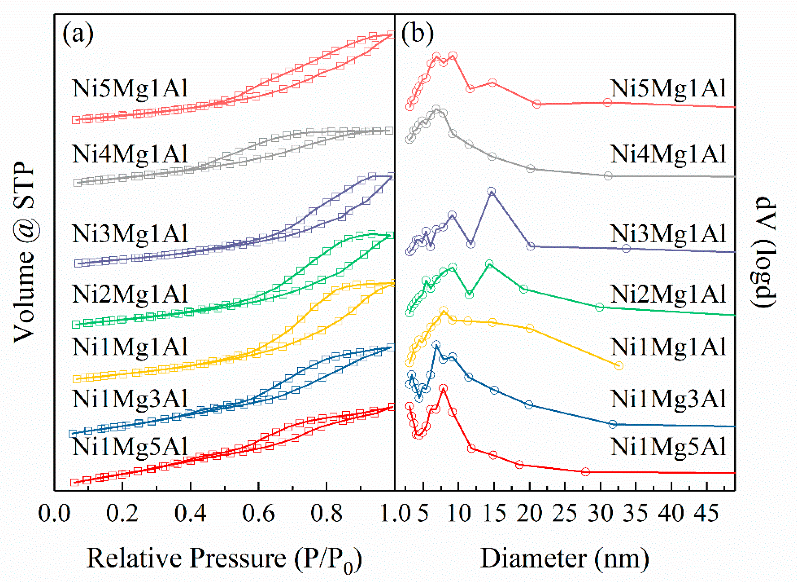
2.1. Characterization of Fresh Catalysts

Phase assignments of the as-synthesized uncalcined samples and calcined samples were carried out on XRD measurements; the results are shown in Figure 1. As can be seen from Figure 1A, all the as-synthesized samples exhibit the similar characteristic diffraction peaks of the hydrotalcite (ICDD 01-070-2151). The hydrotalcite structure can be denoted as [Mg1−x−yNixAly(OH)2]y+(CO32−)y/2·mH2O, which possessed Ni2+, Mg2+, Al3+ cations located in the center of the octahedron unit on the hydrotalcite lamellar [25]. The relative intensity of diffraction peaks related to hydrotalcite is heightened with the increase in Mg/Al ratio from 1/5 to 3/1. As the ratio continues to increase to 4/1 and 5/1, the intensity begins to weaken. Moreover, it can be observed that the characteristic diffraction signals at around 2θ = 11.4°, 22.8°, 34.4°, (representing (003), (006), (009) crystal planes of LDH) shifted to higher angles as the Mg/Al ratio decreased. The shift in these signals was caused by the increased electrostatic interaction between the layer and interlayer due to the excess charge introduced by the trivalent Al3+. The Al3+ with a more positive charge will decrease with the interlayer distance by enhancing the strength of coulombic attractive forces. Except for the typical diffraction peaks of hydrotalcite structure, a crystalline phase of bayerite Al(OH)3 (ICDD 01-074-1119) (diffraction peaks located at 2θ = 18.8°, 20.3°, 40.7°) is observed in the sample of Ni1Mg5Al, Ni1Mg3Al, and Ni1Mg1Al. Meanwhile, the intensity of the diffraction peaks belonged to the Al(OH)3 increase while decreasing the Mg/Al molar ratio. On the other hand, feeble diffraction peaks at 2θ = 18.6°, 38.0°, 50.8° belonged to brucite Mg(OH)2 (ICDD 01-082-2453), appearing in the UC-Ni4Mg1Al samples, and became more intense in the UC-Ni5Mg1Al samples. The chemical composition of layered double hydroxide (LDHs) can be adjusted in a certain range by regulating the feeding ratio of cautions. It is generally recognized that only when the x value (x = M3+/(M2++M3+)) is between 0.2 and 0.33 could a pure phase hydrotalcite structure be obtained [26]. In this research, samples (UC-Ni3Mg1Al, UC-Ni2Mg1Al, UC-Ni1Mg1Al) with rational x could form hydrotalcite with high purity. The excessive addition of caution ions would lead to the corresponding precipitate during the synthetic process [27].
Figure 1C represents the XRD patterns of the calcined NixMgyAl catalysts. The entire diffraction peaks assigned to hydrotalcite completely disappear. For the high Al content samples (Ni1Mg3Al, Ni1Mg5Al), diffraction peaks assigned to NiO (2θ = 37.5°, 43.5°, 63.2°) (ICDD 01-078-0643) and Al2O3 (2θ = 45.6°, 66.7°) (ICDD 00-004-0877) were the sole peaks to be found that could help to deduce that magnesium was well dispersed in the oxide matrix. By increasing the Mg/Al ratio, several variation trends can be realized. The characteristic peaks of Al2O3 are diminished; inversely, the diffraction peaks reflected that MgO (2θ = 36.8°, 42.9°, 62.4°) (ICDD 01-079-0612) emerged for the Mg-rich samples. While increasing the Mg/Al ratio, the diffraction peaks belonging to NiO at 2θ = 43.5° continue to shift slightly to lower diffraction angles, until the diffraction peak arose at 2θ = 42.9° which was affiliated with MgO; this variation implies that the commixture exist. According to Zhu’ s and Zhan’ s works [27,28], MgNiO2 possessed a typical diffraction peak at 2θ = 43.1° located in the range of 42.9° to 43.5°. It is reasonable to infer the coexistence of an MgNiO2 solid solution with the MgO crystal phase in these samples [29]. The vanishment of typical diffraction peaks of NiO in Mg-rich samples indicates the promoting effect of magnesium on nickel dispersion. Besides this, the inexistence of diffraction peaks at 2θ = 65.5° could help to rule out the formation of NiAl2O4 spinel.
The XRD patterns of the NixMgyAl-800 samples, after being reduced at 800 °C for 1 h, are shown in Figure 1D. Diffraction peaks appearing at 2θ = 44.5°, 51.9°, 76.4° can be indexed to the nickel–metal phase (ICDD 01-087-0712), which was regarded as the active site for CDM reaction. The intensity of the diffraction peaks related to nickel decrease seemingly with the increase in Mg/Al molar ratio; this indicates that smaller nickel particles were formed on high Mg content samples based on the Scherrer equation. The Ni0 crystallite size was determined by applying the Scherrer equation to the main Ni (200) diffraction peak at 2θ = 51.7° and is listed in Table 1. Notably, the MgO phase dominates on high Mg content samples, while the Al2O3 phase takes place on high Al content samples. A more detailed analysis of the spectrogram reveals the possible existence of spinel phases (e.g., NiAl2O4 (ICDD 01-078-0552) and MgAl2O4 (ICDD 01-082-2424)), but it can hardly distinguish them due to the overlapping of their diffraction peaks [29,30]. The disappearance of the relative diffraction peaks located at 2θ = 65.3° for high Mg content samples indicates the inhibiting effect of Mg addition on the formation of spinel phases. Combined with the former analysis, the greater tendency to form an MgO-NiO solid solution (e.g., MgNiO2) may be the main reason for the inhibition of spinel formation on Mg-rich samples [31].
The hydrogen temperature-programmed reduction (H2-TPR) characterization was employed to investigate the reducibility of the nickel species and to study the metal–support interaction of calcined NixMgyAl samples. The results are displayed in Figure 2. Evidently, the strength of the interaction between active metal and the support would have a significant influence on the TPR profiles of the catalysts [29,32]. As the other oxides, with the exception of NiO, cannot be reduced under the restrictive H2-TPR atmosphere, the hydrogen consumption peaks can be assigned to the reduction of Ni2+ to Ni0 exclusively. All seven samples exhibit broad hydrogen consumption peaks at relatively high temperatures beyond 550 °C, indicating a strong interaction between Ni2+ and the support. It can be seen from Figure 2 that the main hydrogen consumption peaks shift to higher temperature companies with the increase of the Mg/Al ratio. It was proposed that introduction of Mg would have an effective stabilization effect on nickel species attributed to enhanced metal–support interaction [33]. The strong metal–support interaction can not only promote the dispersion of nickel species on calcined catalysts but also prevent the sintering of nickel species during the reduction process, which may lead to smaller nickel particles [34,35]. Through more elaborate analysis, the hydrogen consumption peaks of each sample can be deconvoluted by Gaussian type into several distinguished peaks. With the increase in Mg/Al ratio, the peaks at relatively low temperature can be assigned to the reduction in Ni2+ in the Ni-Mg-Al matrix generated from the calcination of hydrotalcite precursors [36]. When increasing the Mg content, the polarization effect on Ni-O bonds incurred by Al3+ and Mg2+ ions in the metal oxides becomes stronger, thus hindering the reduction in Ni2+ species [37]. The small reduction peaks located between 800 and 900 °C in Ni1Mg5Al, Ni1Mg3Al, Ni1Mg1Al samples can be associated with the reduction in NiAl2O4 species, whose existence has also been confirmed by XRD characterization results, shown in Figure 1C [33]. For the sample of Ni2Mg1Al and Ni3Mg1Al, other than the reduction peak at relatively low temperatures represented for the Ni2+ in Mg-Al matrix, the peaks positioned at a higher temperature than low Mg content samples could be identified as the reduction in NiAl2O4 spinel which may also be generated during the TPR process [30,38,39]. Adversely, continuing to increase the Mg content could result in the reduction peaks shifting to a slightly lower temperature. The reduction peak located at a relatively low temperature could be assumed for the reduction in MgNiO2 [40], which could be confirmed by the XRD patterns of the calcined samples in Figure 1C. In conclusion, the strong metal–support interaction on NixMgyAl catalysts can be modulated through modified Mg addition, which should play an important role in improving the dispersion of nickel species.
To further determine the promotion effect of the metal–support interaction on decreasing the dimension of reduced Ni particles, TEM characterization was carried out on NixMgyAl-800 samples. The results are shown in Figure 3. After reduction, Ni particles, represented by black spots, are spread out on the substrate. Thanks to the confinement effect of the LDH structure, the round-like nickel particles are nanosized and dispersed homogeneously on the carrier. By counting at least 200 random particles on different regions of each catalyst, the nickel particle size distributions are calculated and shown as the insert figures in each picture. It can be found that the mean nickel particle size decreases with the increase in Mg/Al ratio from 25.4 nm on Ni1Mg5Al-800 catalyst to 13.2 nm on Ni5Mg1Al-800 catalyst. This result is consistent with the intensity variation in reflection peaks related to Ni in Figure 1D. As have already stated in the TPR analysis, the metal–support interaction became stronger by increasing the amount of Mg addition and could affect the electronic structure of the metal and prevent the nickel particle from sintering during calcination and reduction processes. Therefore, it can be seen that by adjusting the Mg/Al molar ratio of synthesis gel in the co-precipitation method, the size of nickel particles formed after reduction can be regulated favorably.
The physical structure of the reduced NixMgyAl-800 samples was characterized by nitrogen adsorption isotherms performed at −196 °C; the results are exhibited in Figure 4. All the seven prepared samples display typical IV isotherms with H1 hysteresis loops, which are generated by the capillary condensation effect, demonstrating the existence of mesoporous in all the samples. The specific surface area is calculated by the BET method in the relative pressure range of 0.05–0.30 of the adsorption branch, and the pore volume is calculated from the adsorption isotherm at relative pressure of 0.99; both the results are shown in Table 1. The BET surface increased with the decrease in Mg/Al ratio, indicating that Al plays a vital role in maintaining a large surface area; the same phenomenon was also observed by Sun et al. [41]. The pore size distributions become broad then narrow again with the increasing Mg/Al ratio, which implied a slight change in catalysts’ structure with the variation in Mg/Al ratios. As shown in Table 1, the mean particle size does not seem to change much with the variation in Mg/Al ratios.

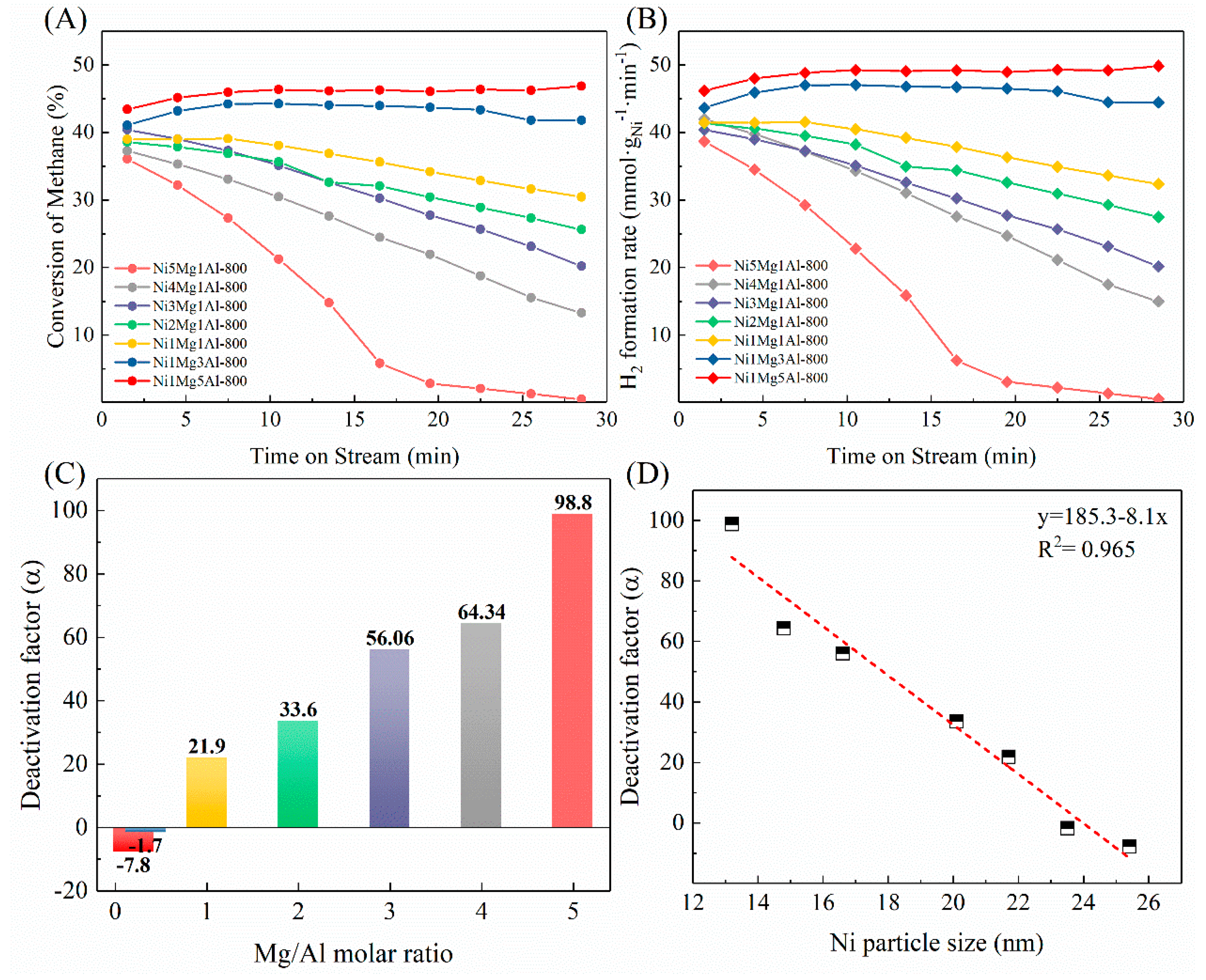
2.2. The Catalytic Activity of NixMgyAl-800 Catalysts on CDM Reaction

The CDM reaction was employed to examine the methane cracking activity and stability of NixMgyAl-800 catalysts. As can be seen from Table 1, the nickel content on each NixMgyAl catalyst is not consistent as a result of the difference in the preparation environment. Therefore, the hydrogen formation rate is further calculated to eliminate the effect of different nickel loadings. All the results are given in Figure 5. As can be seen from Figure 5B, the initial hydrogen formation rates seem to increase in line with the decreasing Mg/Al molar ratio, but the variations are relatively small. The Ni1Mg5Al catalyst has the highest H2 formation rate of 46 mmol·gNi−1·min−1, in contrast with the 39 mmol·gNi−1·min−1 of Ni5Mg1Al catalyst, which is the lowest among the seven catalysts. Duprez and Kim have reported that metal particle size could influence both the catalytic activity of methane conversion and coke formation [18,42]. Furthermore, depending on the DFT calculations, Bengaard et al. stated that the steps sites (e.g., Ni (211)) on nickel particles were more active than the close-packed surface (e.g., Ni (111)) [43]. Therefore, methane conversion reactions have been recognized as size-dependent reactions. The nickel atoms positioned at the corner and edge sites are more active than the atoms on terrace due to the higher degree of unsaturation [44]. However, only when the nickel particle size is less than 10 nm would the fraction of each type of surface atoms change significantly [45]. In this research, the nickel particles’ size on the NixMgyAl catalysts is larger than 13 nm, and therefore we can infer that the particle size effect on the initial catalytic activity is feeble. Besides this, the data of catalyst activity are observed as averages over time. Therefore, it can be considered that the initial activity of these catalysts is very close. In contrast, the activities of the catalysts have changed differently with the extension of reaction time. During the 30 min reaction time, the H2 formation rates of Ni1Mg5Al and Ni1Mg3Al catalysts were extremely stable in the range of 43–48%. The other five catalysts experienced varying degrees of deactivation as the reaction proceeded. Obviously, the catalyst deactivation was more severe, with the Mg/Al molar ratio increasing. To depict the degree of deactivation more intuitively, we defined the deactivation factor (α) as the ratio of the change in reactivity to the initial activity (Equation (2)). The results are shown in Figure 5C.
D e a c t i v a t i o n   f a c t o r   ( α ) = R H 2 ( t = 1.5   min ) R H 2 ( t = 28.5   min ) R H 2 ( t = 1.5   min ) × 100
With the increase in Mg/Al ratio, the deactivation factor (α) becomes larger, which indicates that the more severe catalyst deactivated. Since the magnesium–aluminum oxide support is inactive for methane cracking at the reaction temperature, it can be further inferred that the smaller the nickel particles, the faster the catalyst is deactivated. Moreover, Figure 5D shows the deactivation factor as a function of nickel particle size. The linear correlation between deactivation factor and nickel particle size indicated that the deactivation of the catalyst is closely related to the size of nickel particles.

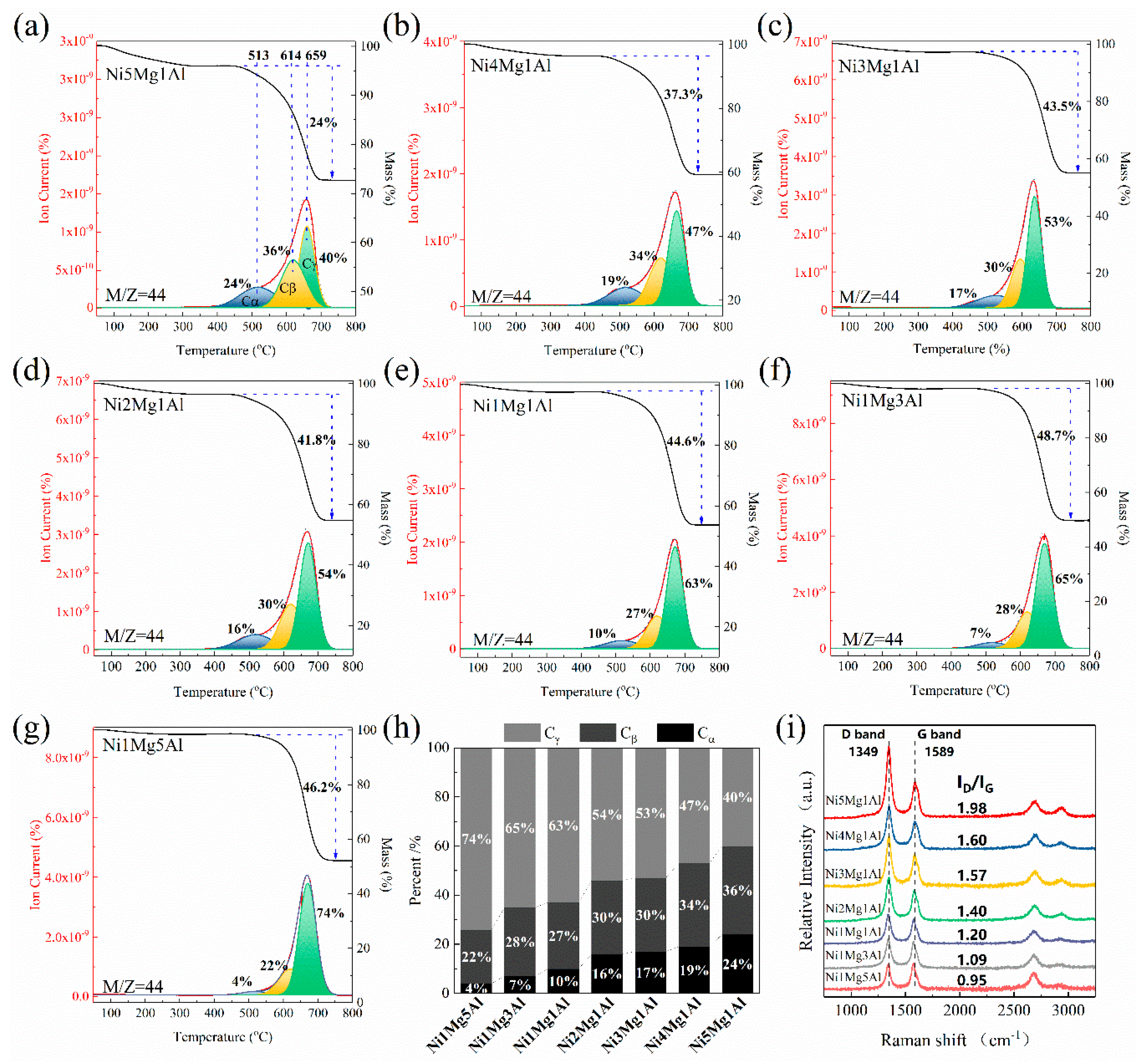
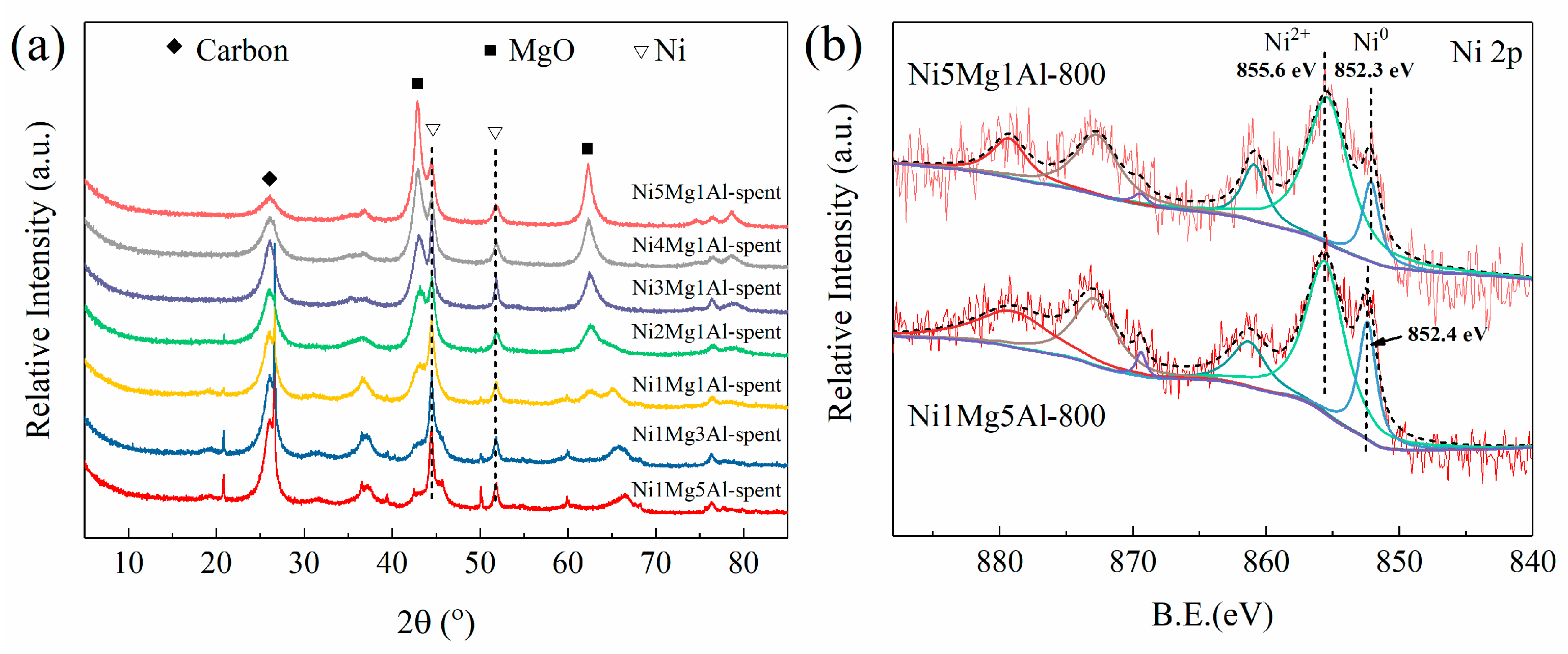
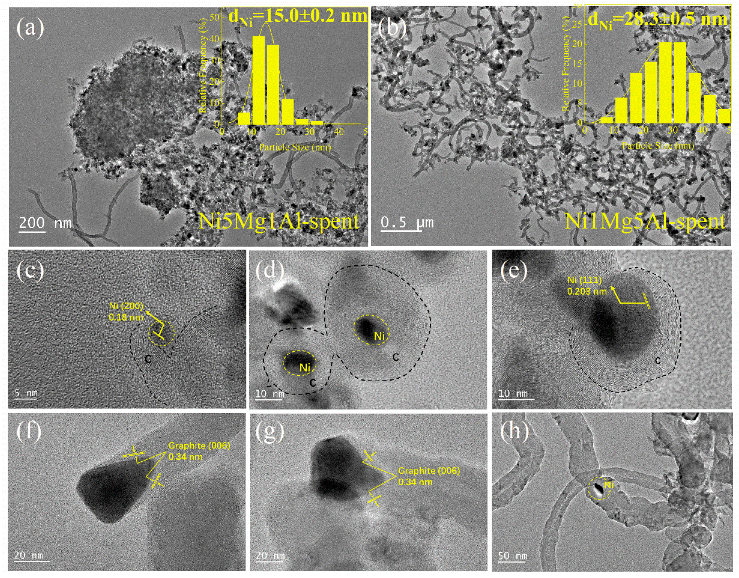
2.3. Characterization of Spent Catalysts
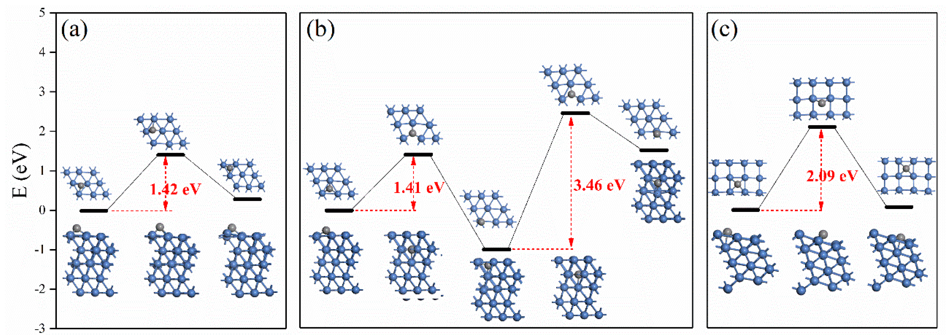
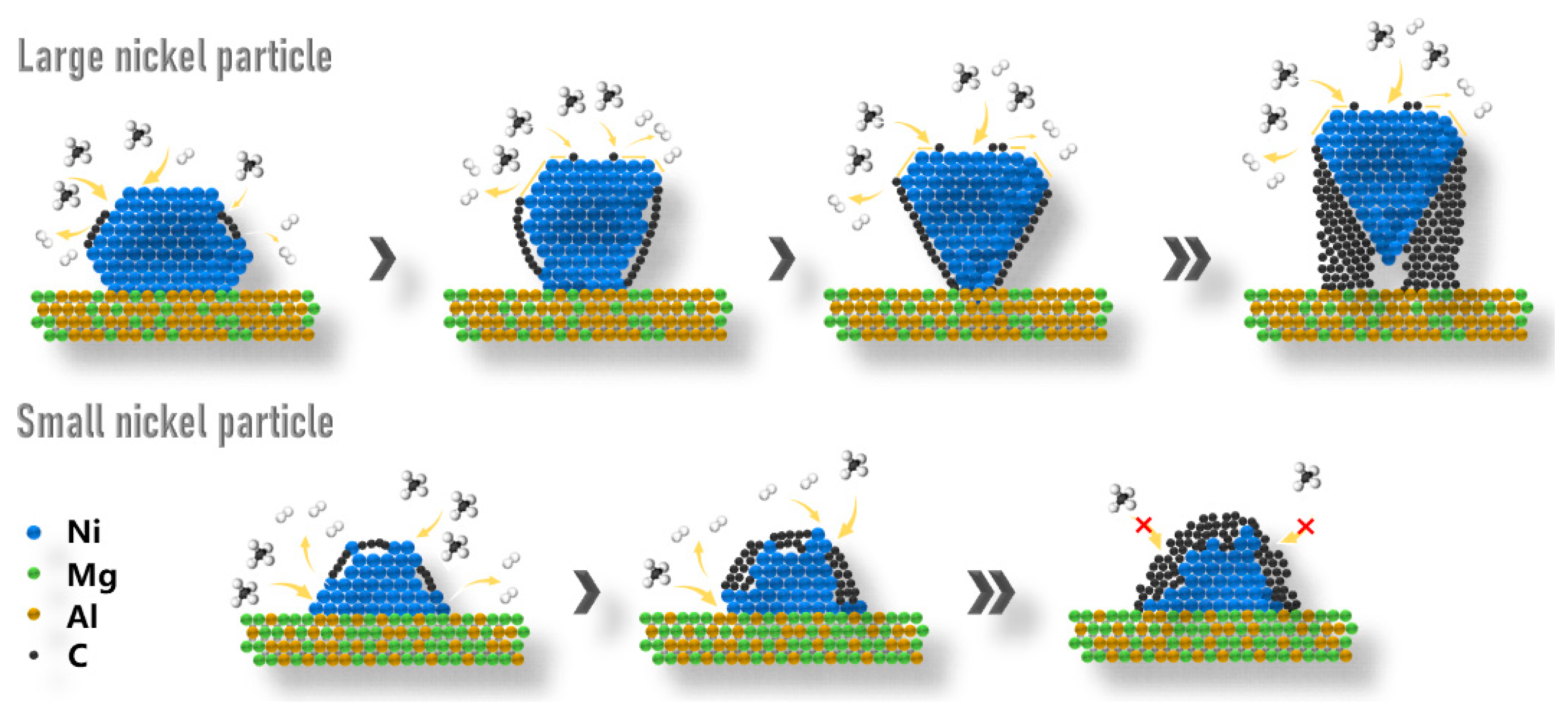
To explore the reasons for the different catalytic behaviors of NixMgyAl-800 catalysts, multiple characterizations were performed on the spent catalysts. The TG-MS analysis was adopted to determine the amount of coke deposition on the spent catalysts. As can be seen in Figure 6, the weight loss before 300 °C is assigned to the elimination of adsorbed water on the catalysts. Moreover, the weight loss between 400 and 800 °C is attributed to the oxidation of deposited carbon. The amount of deposited carbon decreases according to the increase in Mg/Al molar ratio, which is owing to the rapid deactivation rate for high Mg content catalysts. In consideration of the disturbance of TG profile caused by the oxidation of the support and the reduced nickel species, the MS signal of CO2 was detected to analyze the deposited carbon more accurately. As is clearly shown in Figure 6a–g, the multiplet type for MS signal indicates the existence of multiple carbon species. After the curve fitting of the Gauss type for the peaks, three segregated peaks can be distinguished, which are located at oxidation temperatures of 513, 614, and 659 °C. The three types of deposited carbon were denoted as Cα, Cβ, and Cγ, respectively. The number of different types of carbon species on each catalyst was obtained by integrating the peak area and visualized in Figure 6h. As can be seen in the graph, the proportion of Cα and Cβ increases with the increase in Mg/Al ratio, while the proportion of Cγ decreases. The graphitization degree of the deposited carbon on spent catalysts was analyzed by Raman spectroscopy and shown in Figure 6i. Two distinguished peaks around 1349 and 1589 cm−1 can be assigned to the D-band and G-band, respectively [46]. The D-band is indicative of the disordered structure of defect-rich carbon, which is more reactive and easily vaporized by oxygen medium [47]. The G-band is ascribed to graphitic material with ordered and well-graphitized sp2 carbon species, which is harder to gasify [48]. The ratio of the intensity of the D- and G- band (ID/IG) was calculated to characterize the degree of disorder/order in carbon structure [47,49]; the values are marked in Figure 6i. The ID/IG value increases along with the increase in Mg/Al ratio. The result indicated that more disordered carbon species would be formed on catalysts with a high Mg/Al ratio. Combining analysis results of TG-MS and Raman characterizations, Cα should be attributed to disordered carbon, while Cβ should be attributed to ordered carbon species with defects and Cγ to ordered carbon with intact structure.
XRD characterization was performed on spent catalysts to explore whether the catalyst composition changed during the reaction. As shown in Figure 7a, we cannot see an obvious change in structural composition, except for the emergence of a diffraction peak located at 2θ = 26°, which represents carbon (ICDD 00-026-1076). The increase in the intensity of this diffraction peak with the decrease in Mg/Al ratio indicates the decrease in carbon content on catalysts, which is consistent with the trend of weight loss depicted in TG characterization. Meanwhile, the formation of inactive surface nickel species (NiCx or NiO) can be excluded because no corresponding characteristic diffraction peak is observed.
Subsequently, the particle size distribution of nickel particles after the reaction was determined by TEM. As shown in Figure 8a,b, the average particle size of Ni5Mg1Al-800 and Ni1Mg5Al-800 catalysts, initially 13.2 and 25.4 nm, slightly increased to 15.0 and 28.3 nm, respectively, after methane decomposition reaction. For comparison, the particle sizes of nickel on all the used catalysts were estimated by Scherrer equation using the FWHW of diffraction signal at 2θ = 51.7°. The nickel particle sizes on all the catalysts increased slightly after the reaction, but the tendency of decreasing nickel particle size with an increase in Mg/Al ratio still existed. The estimated corresponding active surface area decrease in nickel for each catalyst is negligible [50]. Therefore, the possibility of catalyst deactivation caused by nickel particle agglomeration may be ruled out. From the characterization results of the spent catalysts above, it can be deduced that the deactivation of catalysts is closely related to the type of carbon deposited on the catalyst. HRTEM characterizations were performed on used Ni5Mg1Al-800 and Ni1Mg5Al-800 catalysts, which have the most significant difference in deactivation behaviors. As presented in Figure 8b, the surface of Ni1Mg5Al-800 catalyst was severely covered with carbon nanotubes. On the contrary, few carbon nanotubes can be observed on the Ni5Mg1Al-800 catalyst (Figure 8a). HRTEM was further employed to observe the morphology of the deposited carbon. It is observed from Figure 8c–e, the marked interplanar distances of 0.18 and 0.203 nm are in accordance with the lattice spacing of the (200) and (111) surfaces of metallic FCC type Ni crystallites [37], which dispersed randomly on amorphous Mg(AlO) support. Carbonaceous species with amorphous structure were formed and tightly wrapped around the nickel particles, shaped like onions. The fringes of the carbon shell can be seen but were not well arranged. This kind of carbon can be identified as Cα, which should be responsible for the catalyst deactivation through fully encapsulating the active sites and prohibiting contact with the reactants [51,52]. However, the Cα is the most easily removed carbon species by oxidation. For the spent Ni1Mg5Al-800 catalyst, the most common seen carbon structure is carbon nanotubes with nickel particles located at the top (Figure 8f,g). The graphite layers are well arranged in an ordered manner and the lattice spacing is measured to be 0.34 nm, which is consistent with the (002) planes of graphite. It has been suggested that the carbon atoms generated from the breaking of C-H bonds on Ni active surface would spread to the metal–support interface and force the growth of the nanotube [53]. This type of carbon is identified as Cγ. The nickel particles located at the tip of carbon nanotubes can keep exposing active sites and reserve catalysis activity. Cγ would be the hardest carbon species to be removed by oxidation [52]. Besides this, the carbon nanotubes embedding small pieces of Ni particles can be recognized in Figure 8h. Due to the inclusion of fragmented nickel particles, the regularity of carbon nanotubes is reduced. Similar defective carbon nanotubes can be deemed as Cβ. The Cβ species can also lead to catalyst deactivation due to limitations regarding the contact between active sites and reactants. Combined with the characterizations of TG-MS and HRTEM, we conclude that the largest amount of amorphous Cα on high-Mg-content catalysts led to the catalyst deactivation, while the most formed ordered carbon nanotubes on high-Al-content catalysts help to maintain the catalysts’ stability.

2.4. Discussions

Investigation into the formation of carbonaceous species is of prime importance as it can help to design a rational catalyst structure to avoid breakdown of catalysts. Similar to what we found in our work, several carbon structures, for example, CNTs, CNFs, carbon onions and encapsulated carbon species have been obtained in the methane conversion reactions [51,52,53,54,55]. In a widely accepted viewpoint, the strength of the interaction between the carrier and metal particles was considered to be the determinant of the formation of different types of carbon species [37,53,56,57]. It has been proposed that the carbon atoms generated by the break of the C-H bond at nickel particle surface would diffuse to the rear end of nickel and be incorporated into the new graphene layers of the growing nanotubes [58]. The weak interaction between the nickel particle and support would result in the tip-growth manner of carbon nanotube, whereas strong interaction brought about base-growth or encapsulated carbon. The electronic states of the surface nickel atom on Ni5Mg1Al-800 and Ni1Mg5Al-800 catalysts were investigated by XPS characterization. In the high-resolution Ni 2p spectra shown in Figure 7b, the peak at the binding energy of 855.6 eV is assigned to Ni2+, whose formation results from the inevitable exposure in air during the sample transfer process [59]. For the Ni5Mg1Al-800 catalysts, the peak at 852.3 eV can be assigned to metallic Ni0 [60]. The peak slightly shifts by merely 0.1 eV to the binding energy of 852.4 eV for Ni1Mg5Al-800 catalysts. Therefore, it can be assumed that the strength of the metal–support interaction does not change on different NixMgyAl-800 catalysts. The participation of the metal–support interaction in the formation of different types of carbon deposits can be excluded in this research.
The variation in nickel particle size should be recognized as the main reason for the change in carbon deposits’ type. Some outstanding studies have revealed the atomistic growth mechanism of carbon nanotube by combining experiments and DFT calculations. As confirmed by HRTEM and DFT calculations, most researchers have reached a consensus that the step-edge sites of metal particles acted as the growth center for grapheme [43,61,62,63]. The growth of carbon nanotubes can be elaborated as follows. As the hydrocarbon cracking reaction begins, the produced carbon atoms are adsorbed on the metal particles surfaces, forming steps on the surfaces. The graphene embryo begins to grow on the newly formed step sites or pre-existing step sites on the metal particle. Since the binding energy of Ni-C is stronger than the energy of the Ni-Ni bond, the nickel atoms located at the graphene–nickel interface will migrate towards the rear end of the nickel cluster through surface diffusion with the growth of graphene. As a consequence, accompanied by the vanish of step-edges, a new graphene layer is eased at the nickel–graphene interface.
As observed by Rao et al., the growing graphene layer would bond to steps and cover part of the terrace, thus the migration of carbon atoms, which is generated by methane cracking from the free metal surface to the interface, is crucial for the continuous growth of carbon nanotube. The migration path of carbon atoms is still controversial. Two distinct paths named bulk diffusion [64,65] and surface diffusion [66,67] were proposed and evidenced by researchers. Taking the most easily exposed Ni (111) packed surface as an example, we calculated the carbon atom diffusion barriers for each path, utilizing DFT simulation. As can be seen in Figure 9, the diffusion barrier of C on Ni (111) surface was calculated to be 1.42 eV, which is very close to the barrier energy of 1.41 eV as the C atom diffuses from the surface to the second layer of nickel particles. The calculated barrier energy agreed well with the value reported by Nørskov et al. [58]. However, the barrier energy increased to 3.46 eV when the carbon atom continues to permeate into the third layer of nickel, which is much larger than diffusion on the surface. Therefore, we suggest that the surface diffusion path plays a major role in C atoms transportation. Hereafter, the barrier energy of C atoms transported on the Ni (511) step surface and Ni (100) terrace surface was calculated as 2.09 eV, which is larger than that on Ni (111) surface. The result is consistent with the finding presented by Li et al., indicating that the adsorption energy of C atoms on Ni (553) was larger than on Ni (111) surface [68]. This result indicates that the C atoms are easier to migrate on the terrace surface of nickel than the step surface. Therefore, we suggested that the low-energy terrace Ni (111) surface should act as the “plant” for carbon atom production, not only because Ni (111) is the most abundant and easily exposed facet, but also because of the advantage of the easy migration of carbon atoms. The generated carbon atoms by methane decomposition can easily diffuse to the adjacent step sites to maintain the growth of carbon nanotube. Another important factor to consider is that the CDM reaction has been proven to be structurally sensitive to nickel particle size; small nickel particles showed high methane cracking activity [69]. That can be explained by the lower activation barriers of CHx species dissociation on uncoordinated crystallographic planes (e.g., Ni (553) or Ni (100)) compared with the packed surface (e.g., Ni (111)), which are greater on small-sized particles [70]. On the contrary, a large amount of Ni (111) surfaces are present on the large nickel particles. Although the methane dissolution rate of Ni (111) is low, sufficient carbon atoms can be produced to meet the needs of graphene growth on step-edge. This explains why it is easier to form carbon nanotubes on large nickel particles. For small-sized nickel particles, the initial methane cracking rate was increased due to the rich defect sites. A large number of carbon deposits started to grow rapidly at the pre-existing step sites. As the step sites are covered with graphene embryo, the carbon atoms required by nanotube growth cannot be satisfied by generation on a small number of Ni (111), thus inhibiting the growth of the new graphite layer. Besides, the migration of nickel atoms during the growth of graphene is limited due to the anchoring of nickel particles by multiple carbon layers. Eventually, the encapsulation carbon is formed by combining the carbon layers growing in multiple directions on nickel particles, leading to the deactivation of the catalyst [71]. It can be concluded that the ratio of terrace and step sites changes induced by the variation in nickel particle size affects the growth of different carbon deposits. In order to facilitate the understanding of the process, the stated formation mechanisms of different carbon species were visualized in Figure 10.
As pointed out in our previous article [55], we suggest that the fluidized-bed reactor was more suitable for CDM reaction than fixed-bed reactor, considering that the deactivated catalysts required frequent regeneration. The regeneration stability is critical for catalysts used in the fluidized-bed reactor. The catalyst with small-sized nickel particles not only processes high methane conversion rate but also produces coated carbon that can be removed at lower temperatures. Moreover, the coated carbon anchors nickel particles on the support, thus improving regeneration stability. Within the scope of this research, we believe that the Ni5Mg1Al catalyst with the smallest nickel particles is most suitable for CDM reactions. The insights presented in this article may provide guidance for the rational design of catalysts for CDM reaction, and also shed new light on the interpretation of the deactivation mechanism of other methane conversion reactions (e.g., methane steam reforming (SMR) and methane dry reforming (DRM)).

3. Experimental Section

3.1. Chemicals

Aluminum nitrate nonahydrate (Al(NO3)3·9H2O), magnesium nitrate hexahydrate (Mg(NO3)2·6H2O), nickel (II) nitrate hexahydrate (Ni(NO3)2·6H2O) and sodium carbonate anhydrous (Na2CO3) were purchased from Sinopham Chemical Reagent Co., Ltd. (Shanghai, China). Sodium hydroxide (NaOH) was supplied by Xilong Scientific Co., Ltd. (Shantou, Guangdong province, China). All the chemicals were of analytical purity. All the experimental gases used were supplied by Qingdao Airox Gases & Chemicals Co., Ltd. (Qingdao, Shandong Province, China). with each component of 99.999% purity, except 99.99% purity for methane.

3.2. Catalyst Preparation

A series of NiMgAl catalysts with different Mg/Al molar ratios were prepared by the co-precipitation method. The value of Mg2+/Al3+ molar ratio was varied from 5:1 to 1:5. In this series, the nickel content in the initial preparing gel of catalysts was fixed to 10 wt%. To raise a typical procedure of catalyst preparation, solution A was prepared by dissolving a pre-determined amount of Al(NO3)3·9H2O, Mg (NO3)2·6H2O, Ni(NO3)2·6H2O in 150 mL deionized water. A precalculated amount of Na2CO3 and NaOH were dissolved in 150 mL deionized water to obtain a solution B, which had a molar concentration of 0.8 and 1.2 mol/L for Na2CO3 and NaOH respectively. Both solutions A and B were filled in separating funnel and added dropwise into a three-necked flask simultaneously under vigorous stirring at 65 °C. During the dropwise mixing process, the pH of the corresponding slurry was maintained at 10.5 by adding dropwise of 1 M NaOH aqueous solution. The obtained slurry was stirred vigorously for 24 h at 65 °C then aged static for another 24 h at the same temperature, after which the product was filtered by deionized water and then oven-dried for 12 h at 60 °C. Finally, the obtained samples were calcined at 600 °C in a muffle oven for 3 h with a heating rate of 2 °C/min. For the sake of distinction, the obtained NiMgAl mixed-oxide catalysts were designated as NixMgyAl, where x and y each represent the nominal Mg molar ratio and Al molar ratio. Correspondingly, the as-synthesized uncalcined samples were denoted as UC-NixMgyAl, and the catalysts reduced at 800 °C were named as NixMgyAl-800. More details of the seven NiMgAl mixed-oxide catalysts are listed in Table 1.

3.3. Characterization Techniques

Specific surface areas and pore structure properties of the catalysts were determined by adsorption–desorption measurements of nitrogen at liquid nitrogen temperature carrying on a Quantachrome Automated Gas Sorption apparatus (Graz, Austria). Prior to measurement, all samples were evacuated at 300 °C for 4 h at a pressure of 1.0 × 10⁻³ kPa to ensure complete removal of adsorbed moisture. The pore size distribution was calculated from the adsorption branches of the isotherms using BJH methods. The specific surface area was calculated by the Brunaur–Emmett–Teller (BET) method in the relative pressure range of 0.05–0.30. The total pore volume was determined by nitrogen adsorption quantity at the relative pressure of 0.99.
X-ray diffraction (XRD) characterization of all the samples was carried on an X’pert PRO MPD diffractometer (PANalytical Company, Amesterdam, The Netherlands) with Cu Kα radiation (40 kV, 40 mA), recording from 5° to 85° at a scan speed of 5°/min.
The reduction behavior of catalyst samples was determined by the temperature-programmed reduction in hydrogen (H2-TPR) on AutoChem II 2920 apparatus (Micromeritics, Atlanta, USA). The sample (about 0.1 g) was pretreated at 600 °C for 1 h under flowing Argon (30 mL/min) to ensure the complete removal of impurities. H2-TPR measurement started after the TCD signals stabilized at 50 °C under a mixture of 10 vol.% H2/Ar (30 mL/min), temperature ramp was 3 °C/min, from 50 °C up to the final isotherm of 1000 °C.
Transmission electron microscopy (TEM) images were collected by a JEOL JEM-2100 analytical electron microscope (JEOL, Akishima, Tokyo) with an accelerating voltage of 200 kV. A suitable amount of catalysts were dispersed into 1 mL ethanol and sonicated for 15 min. Then, one drop of the solution was added dropwise onto the copper grid (supplied by Beijing Zhongjingkeyi Technology Co., Ltd. Beijing, China) before the test. For the counting of nickel particle size on the reduced catalysts, different regions of samples which were already reduced under a flow of 5 vol.% H2/N2 at pre-set temperature for 1 h were imaged randomly. The particle size distributions were summed by at least 200 particles for each sample.
Combined thermogravimetry, differential scanning calorimetry, and mass spectrometry analysis (TG-DSC-MS) was performed on a QMS 403 Aeolos Quadro apparatus (Netzsch, Bavaria, Germany) under a high-purity N2-atmosphere at a heating rate of 20 °C/min from 30 to 800 °C on a thermal analysis-quadrupole mass spectrometer manufactured by Netzsch. The signal of CO2 (m/Z = 44) in the effluent gas was collected for distinguishing different kinds of deposited carbon species.
The Raman spectra of the spent catalysts were obtained at room temperature using a SENTERRA dispersive Raman microscope (Bruker, Billerica, MA, USA) equipped with an Nd: YAG diode laser with a wavelength of 532 nm, and data were collected in the range 1000~3000 cm−1.
X-ray photoelectronic spectra (XPS) was recorded by Thermo Fisher ESCALAB 250 analyzer instrument (Thermo Fisher Scientific, Waltham, MA, USA) with Al K radiation. The banding energy of all samples was calibrated using the C 1 s adventitious carbon peak with EB fixed at 284.6 eV.

3.4. Catalytic Evaluation

Activity tests of catalysts for methane decomposition reaction were performed under atmospheric pressure in a continuous downflow vertical fixed-bed reactor (8 mm i.d.), with 0.2 g of catalysts (sieved for 20–40 mesh) loaded in the isothermal zone of the reactor. Quartz sands (20–40 mesh) were used to support the catalyst bed and reduce the dead volume of the reactor, which was considered to have negligible catalytic activity for methane decomposition at the reaction temperature. Prior to reaction, catalysts were degassed at reaction temperature in a high-purity nitrogen flow for 30 min to remove adsorbed oxygen and water from the catalyst surface. Subsequently, a gas mixture of 10% H2/N2 (50 mL/min) was introduced into the reactor at 800 °C for 1 h to reduce the nickel oxide species on each catalyst. After purging with N2 for another 15 min to eliminate residual reduction gas, the reactor was settled to the desired reaction temperature. Reactant gas of methane (99.99% purity) with no dilution was purged into the reactor to start methane decomposition reaction at a fixed flow rate of 30 mL/min. The composition of effluent gas products was analyzed by a Scion 456-GC Chromatograph (Techcomp, Beijing, China) equipped with a TCD detector, 13X, and 5A molecular sieve columns.
During the methane cracking reactions, H2 and CH4 were the only products in the effluent gases, which has been confirmed by the chromatographic analysis results. Hence, the methane conversion ( x C H 4 ) and hydrogen formation rate ( R H 2 ) were calculated using the following equation
x C H 4 % = 1 2 C H 2 1 2 C H 2 + C C H 4 × 100 %
where C H 2 and C C H 4 are the concentrations of hydrogen and methane determined by gas chromatograph
R H 2 % = F C H 4 × x C H 4 × 2 W c a t × w N i × 100 %
where W c a t is the weight of the catalysts in g, F C H 4 is the molar rate of methane conversion in mmol/min, and w N i is the weight percentage of nickel on the catalyst.

3.5. Density Functional Theory Calculations

The density functional calculations exhibited in this work were implemented under the Castep program package included in the Materials Studio 8.0 (Accelrys Software Inc., San Diego, CA, USA) [72]. The Ni (111), Ni (511) surfaces were cut out from the optimized Ni crystal. As the FCC type crystal structure of Ni metal, we selected the most easily exposed Ni (111) to represent the surface of the Ni catalyst, and the Ni (511) model was regarded as the corner active site [68]. A p (3 × 3) supercell with a periodic 5-layer slab was constructed in the Ni (111) model, and the bottom two layers were fixed. We chose 4 × 3 × 1 Monkhorst-Pack k-point mesh sampling for Brillouin-zone integration and an energy cutoff of 300 eV for a plane wave basis set, while, for the modeling of Ni (511) surface, a five-layer p (4 × 3) slab was adopted with the lower two layers fixed and the upper three layers relaxed. For both the two models, each slab was separated by a vacuum of 20 Å to guarantee that the interaction between the neighboring cells was negligible in the z-direction. Based on the generalized gradient approximation (GGA), the Perdew–Burke–Ernzerhof (PBE) exchange-correlation functional was used. The LST/QST method was employed to find the transition states for each possibility of carbon migration [73]. All of the geometric configurations were carefully optimized, and the convergence of total energy was also indispensable considered.

4. Conclusions

In this work, a series of NiMgAl mixed oxide catalysts with different nickel particle sizes was prepared by the co-precipitation method through regulating the Mg/Al molar ratio. Nickel particles with mean particle size varying from 13.2 to 25.4 nm were formed on the catalysts after H2 reduction at 800 °C for 1 h. When adopted in the CDM reaction, the catalysts with different nickel particle sizes exhibited different deactivation behaviors. The catalysts with large nickel particles could maintain their catalytic activity during the evaluation but deactivated rapidly for catalysts with relatively small nickel particles. Through multiple characterizations, we found that larger nickel particles were more likely to induce the formation of carbon nanotubes, while smaller nickel particles promote the formation of encapsulated carbon. Combined with XPS and DFT calculations, we suggest that the insufficient supply of carbon atoms and rapid nucleation of carbon precursors caused by the lesser terrace/step ratio on smaller nickel particles compared with large particles inhibit the formation of carbon nanotube, leading to the formation of encapsulated carbon species. This work provides valuable insights for correlating nickel particle size with carbon formation in the CDM reaction and guidance for the rational design of nickel-based catalysts for methane conversion reactions.

Author Contributions

W.L.: literature search, figures, study design, data collection, data analysis, data interpretation, writing; H.Y.: study design, data collection, data analysis; C.C.: study design, data collection; D.L.: figures; K.T.: experiment; X.F.: Writing—review & editing; Y.L.: Writing—review & editing; X.C.: Supervision, Funding acquisition, Writing—review & editing; C.Y.: Supervision, Funding acquisition; H.S.: Supervision, Funding acquisition. All authors have read and agreed to the published version of the manuscript.

Funding

This work was funded by the National Natural Science Foundation of China, grant number (21776312).

Conflicts of Interest

There are no conflict to declare.

References

  1. Chen, G.Q.; Wu, X.D.; Guo, J.; Meng, J.; Li, C. Global overview for energy use of the world economy: Household-consumption-based accounting based on the world input-output database (WIOD). Energy Econ. 2019, 81, 835–847. [Google Scholar] [CrossRef]
  2. De_Richter, R.; Caillol, S. Fighting global warming: The potential of photocatalysis against CO2, CH4, N2O, CFCs, tropospheric O3, BC and other major contributors to climate change. J. Photochem. Photobiol. C 2011, 12, 1–19. [Google Scholar] [CrossRef] [Green Version]
  3. Dawood, F.; Anda, M.; Shafiullah, G.M. Hydrogen production for energy: An overview. Int. J. Hydrog. Energy 2020, 45, 3847–3869. [Google Scholar] [CrossRef]
  4. Upham, D.C.; Agarwal, V.; Khechfe, A.; Snodgrass, Z.R.; Gordon, M.J.; Metiu, H.; McFarland, E.W. Catalytic molten metals for the direct conversion of methane to hydrogen and separable carbon. Science 2017, 358, 917. [Google Scholar] [CrossRef] [Green Version]
  5. Qian, J.X.; Chen, T.W.; Enakonda, L.R.; Liu, D.B.; Mignani, G.; Basset, J.-M.; Zhou, L. Methane decomposition to produce COx-free hydrogen and nano-carbon over metal catalysts: A review. Int. J. Hydrog. Energy 2020, 45, 7981–8001. [Google Scholar] [CrossRef]
  6. Li, Y.; Li, D.; Wang, G. Methane decomposition to COx-free hydrogen and nano-carbon material on group 8–10 base metal catalysts: A review. Catal. Today 2011, 162, 1–48. [Google Scholar] [CrossRef]
  7. Wolfbeisser, A.; Klötzer, B.; Mayr, L.; Rameshan, R.; Zemlyanov, D.; Bernardi, J.; Föttinger, K.; Rupprechter, G. Surface modification processes during methane decomposition on Cu-promoted Ni–ZrO2 catalysts. Catal. Sci. Technol. 2015, 5, 967–978. [Google Scholar] [CrossRef] [Green Version]
  8. Kutteri, D.A.; Wang, I.W.; Samanta, A.; Li, L.; Hu, J. Methane decomposition to tip and base grown carbon nanotubes and COx-free H2 over mono- and bimetallic 3d transition metal catalysts. Catal. Sci. Technol. 2018, 8, 858–869. [Google Scholar] [CrossRef]
  9. Amin, A.M.; Croiset, E.; Epling, W. Review of methane catalytic cracking for hydrogen production. Int. J. Hydrog. Energy 2011, 36, 2904–2935. [Google Scholar] [CrossRef]
  10. Zhang, T.; Amiridis, M.D. Hydrogen production via the direct cracking of methane over silica-supported nickel catalysts. Appl. Catal. A Gen. 1998, 167, 161–172. [Google Scholar] [CrossRef]
  11. Forzatti, P.; Lietti, L. Catalyst deactivation. Catal. Today 1999, 52, 165–181. [Google Scholar] [CrossRef]
  12. Gac, W.; Denis, A.; Borowiecki, T.; Kępiński, L. Methane decomposition over Ni–MgO–Al2O3 catalysts. Appl. Catal. A Gen. 2009, 357, 236–243. [Google Scholar] [CrossRef]
  13. Aiello, R.; Fiscus, J.E.; Loye, H.-C.z.; Amiridis, M.D. Hydrogen production via the direct cracking of methane over Ni/SiO2: Catalyst deactivation and regeneration. Appl. Catal. A Gen. 2000, 192, 227–234. [Google Scholar] [CrossRef]
  14. Rahman, M.S.; Croiset, E.; Hudgins, R.R. Catalytic Decomposition of Methane for Hydrogen Production. Top. Catal. 2006, 37, 137–145. [Google Scholar] [CrossRef]
  15. Figueiredo, J.L.; Órfão, J.J.M.; Cunha, A.F. Hydrogen production via methane decomposition on Raney-type catalysts. Int. J. Hydrogen. Energy 2010, 35, 9795–9800. [Google Scholar] [CrossRef]
  16. Ammendola, P.; Chirone, R.; Ruoppolo, G.; Russo, G. Production of hydrogen from thermo-catalytic decomposition of methane in a fluidized bed reactor. Chem. Eng. J. 2009, 154, 287–294. [Google Scholar] [CrossRef]
  17. Li, Y.; Zhang, B.; Tang, X.; Xu, Y.; Shen, W. Hydrogen production from methane decomposition over Ni/CeO2 catalysts. Catal. Commun. 2006, 7, 380–386. [Google Scholar] [CrossRef]
  18. Kim, J.-H.; Suh, D.J.; Park, T.-J.; Kim, K.-L. Effect of metal particle size on coking during CO2 reforming of CH4 over Ni–alumina aerogel catalysts. Appl. Catal. A Gen. 2000, 197, 191–200. [Google Scholar] [CrossRef]
  19. Chen, D.; Christensen, K.O.; Ochoa-Fernández, E.; Yu, Z.; Tøtdal, B.; Latorre, N.; Monzón, A.; Holmen, A. Synthesis of carbon nanofibers: Effects of Ni crystal size during methane decomposition. J. Catal. 2005, 229, 82–96. [Google Scholar] [CrossRef]
  20. Ermakova, M.A.; Ermakov, D.Y.; Kuvshinov, G.G.; Plyasova, L.M. New Nickel Catalysts for the Formation of Filamentous Carbon in the Reaction of Methane Decomposition. J. Catal. 1999, 187, 77–84. [Google Scholar] [CrossRef]
  21. García-Sancho, C.; Guil-Lópeza, R.; Pascual, L.; Maireles-Torres, P.; Navarro, R.M.; Fierro, J.L.G. Optimization of nickel loading of mixed oxide catalyst ex-hydrotalcite for H2 production by methane decomposition. Appl. Catal. A Gen. 2017, 548, 71–82. [Google Scholar] [CrossRef]
  22. Sikander, U.; Samsudin, M.F.; Sufian, S.; KuShaari, K.; Kait, C.F.; Naqvi, S.R.; Chen, W.H. Tailored hydrotalcite-based Mg-Ni-Al catalyst for hydrogen production via methane decomposition: Effect of nickel concentration and spinel-like structures. Int. J. Hydrog. Energy 2019, 44, 14424–14433. [Google Scholar] [CrossRef]
  23. Akri, M.; Zhao, S.; Li, X.; Zang, K.; Lee, A.F.; Isaacs, M.A.; Xi, W.; Gangarajula, Y.; Luo, J.; Ren, Y.; et al. Atomically dispersed nickel as coke-resistant active sites for methane dry reforming. Nat. Commun. 2019, 10, 5181. [Google Scholar] [CrossRef] [Green Version]
  24. Świrk, K.; Motak, M.; Grzybek, T.; Ronning, M.; Costa, P.D. Effect of low loading of yttrium on Ni-based layered double hydroxides in CO2 reforming of CH4. React. Kinet. Mech. Catal. 2019, 126, 611–628. [Google Scholar] [CrossRef]
  25. Li, H.; Jia, X.; Wang, N.; Chen, B.; Xie, X.; Wang, Q.; Huang, L. Auto-thermal reforming of acetic acid over hydrotalcites-derived co-based catalyst: A stable and anti-coking Co/Sr-Alx-O catalyst. Appl. Catal. B Environ. 2020, 267, 118370. [Google Scholar] [CrossRef]
  26. Meza-Fuentes, E.; Rodriguez-Ruiz, J.; Solano-Polo, C.; Rangel, M.C.; Faro, A. Monitoring the structural and textural changes of Ni-Zn-Al hydrotalcites under heating. Thermochim. Acta 2020, 687, 178594. [Google Scholar] [CrossRef]
  27. Zhu, Y.; Zhang, S.; Chen, B.; Zhang, Z.; Shi, C. Effect of Mg/Al ratio of NiMgAl mixed oxide catalyst derived from hydrotalcite for carbon dioxide reforming of methane. Catal. Today 2016, 264, 163–170. [Google Scholar] [CrossRef]
  28. Zhan, Y.; Han, J.; Bao, Z.; Cao, B.; Li, Y.; Street, J.; Yu, F. Biogas reforming of carbon dioxide to syngas production over Ni-Mg-Al catalysts. Mol. Catal. 2017, 436, 248–258. [Google Scholar] [CrossRef]
  29. Broda, M.; Kierzkowska, A.M.; Baudouin, D.; Imtiaz, Q.; Copéret, C.; Müller, C.R. Sorbent-Enhanced Methane Reforming over a Ni–Ca-Based, Bifunctional Catalyst Sorbent. ACS. Catal. 2012, 2, 1635–1646. [Google Scholar] [CrossRef]
  30. Perez-Lopez, O.W.; Senger, A.; Marcilio, N.R.; Lansarin, M.A. Effect of composition and thermal pretreatment on properties of Ni–Mg–Al catalysts for CO2 reforming of methane. Appl. Catal. A Gen. 2006, 303, 234–244. [Google Scholar] [CrossRef]
  31. Takehira, K.; Shishido, T.; Wang, P.; Kosaka, T.; Takaki, K. Autothermal reforming of CH4 over supported Ni catalysts prepared from Mg–Al hydrotalcite-like anionic clay. J. Catal. 2004, 221, 43–54. [Google Scholar] [CrossRef]
  32. González, A.R.; Asencios, Y.J.O.; Assaf, E.M.; Assaf, J.M. Dry reforming of methane on Ni–Mg–Al nano-spheroid oxide catalysts prepared by the sol–gel method from hydrotalcite-like precursors. Appl. Surf. Sci. 2013, 280, 876–887. [Google Scholar] [CrossRef]
  33. Cruz, I.O.; Ribeiro, N.F.P.; Aranda, D.A.G.; Souza, M.M.V.M. Hydrogen production by aqueous-phase reforming of ethanol over nickel catalysts prepared from hydrotalcite precursors. Catal. Commun. 2008, 9, 2606–2611. [Google Scholar] [CrossRef]
  34. Du, X.; Zhang, D.; Shi, L.; Gao, R.; Zhang, J. Coke- and sintering-resistant monolithic catalysts derived from in situ supported hydrotalcite-like films on Al wires for dry reforming of methane. Nanoscale 2013, 5, 2659–2663. [Google Scholar] [CrossRef]
  35. Du, X.; Zhang, D.; Gao, R.; Huang, L.; Shi, L.; Zhang, J. Design of modular catalysts derived from NiMgAl-LDH@m-SiO2 with dual confinement effects for dry reforming of methane. Chem. Commun. 2013, 49, 6770–6772. [Google Scholar] [CrossRef]
  36. Montañez, M.K.; Molina, R.; Moreno, S. Nickel catalysts obtained from hydrotalcites by coprecipitation and urea hydrolysis for hydrogen production. Int. J. Hydrog. Energy 2014, 39, 8225–8237. [Google Scholar] [CrossRef]
  37. Li, M.; Fan, G.; Qin, H.; Li, F. Investigation of the Structure and Catalytic Performance of Highly Dispersed Ni-Based Catalysts for the Growth of Carbon Nanostructures. Ind. Eng. Chem. Res. 2012, 51, 11892–11900. [Google Scholar] [CrossRef]
  38. Mile, B.; Stirling, D.; Zammitt, M.A.; Lovell, A.; Webb, M. The location of nickel oxide and nickel in silica-supported catalysts: Two forms of “NiO” and the assignment of temperature-programmed reduction profiles. J. Catal. 1988, 114, 217–229. [Google Scholar] [CrossRef]
  39. Mangnus, P.J.; Bos, A.; Moulijn, J.A. Temperature-Programmed Reduction of Oxidic and Sulfidic Alumina-Supported NiO, WO3, and NiO-WO3 Catalysts. J. Catal. 1994, 146, 437–448. [Google Scholar] [CrossRef]
  40. Feng, X.-D.; Feng, J.; Li, W.-Y. CO2 reforming of CH4 over a highly active and stable NiMgAl catalyst. Int. J. Hydrog. Energy 2017, 42, 3036–3042. [Google Scholar] [CrossRef]
  41. Sun, Y.; Collins, M.; French, D.; McEvoy, S.; Hart, G.; Stein, W. Investigation into the mechanism of NiMg(Ca)bAlcOx catalytic activity for production of solarised syngas from carbon dioxide reforming of methane. Fuel 2013, 105, 551–558. [Google Scholar] [CrossRef]
  42. Duprez, D.; DeMicheli, M.C.; Marecot, P.; Barbier, J.; Ferretti, O.A.; Ponzi, E.N. Deactivation of steam-reforming model catalysts by coke formation: I. Kinetics of the Formation of Filamentous Carbon in the Hydrogenolysis of cyclopentane on Ni/Al2O3 Catalysts. J. Catal. 1990, 124, 324–335. [Google Scholar] [CrossRef]
  43. Bengaard, H.S.; Nørskov, J.K.; Sehested, J.; Clausen, B.S.; Nielsen, L.P.; Molenbroek, A.M.; Rostrup-Nielsen, J.R. Steam Reforming and Graphite Formation on Ni Catalysts. J. Catal. 2002, 209, 365–384. [Google Scholar] [CrossRef]
  44. Li, Z.; Ji, S.; Liu, Y.; Cao, X.; Tian, S.; Chen, Y.; Niu, Z.; Li, Y. Well-Defined Materials for Heterogeneous Catalysis: From Nanoparticles to Isolated Single-Atom Sites. Chem. Rev. 2020, 120, 623–682. [Google Scholar] [CrossRef]
  45. Hvolbæk, B.; Janssens, T.V.W.; Clausen, B.S.; Falsig, H.; Christensen, C.H.; Nørskov, J.K. Catalytic activity of Au nanoparticles. Nano Today 2007, 2, 14–18. [Google Scholar] [CrossRef]
  46. Zhang, S.; Muratsugu, S.; Ishiguro, N.; Tada, M. Ceria-Doped Ni/SBA-16 Catalysts for Dry Reforming of Methane. ACS. Catal. 2013, 3, 1855–1864. [Google Scholar] [CrossRef]
  47. Bu, K.; Kuboon, S.; Deng, J.; Li, H.; Yan, T.; Chen, G.; Shi, L.; Zhang, D. Methane dry reforming over boron nitride interface-confined and LDHs-derived Ni catalysts. Appl. Catal. B Environ. 2019, 252, 86–97. [Google Scholar] [CrossRef]
  48. Marinho, A.L.A.; Rabelo-Neto, R.C.; Epron, F.; Bion, N.; Toniolo, F.S.; Noronha, F.B. Embedded Ni nanoparticles in CeZrO2 as stable catalyst for dry reforming of methane. Appl. Catal. B Environ. 2020, 268, 118387. [Google Scholar] [CrossRef]
  49. Silva, C.G.; Passos, F.B.; da Silva, V.T. Influence of the support on the activity of a supported nickel-promoted molybdenum carbide catalyst for dry reforming of methane. J. Catal. 2019, 375, 507–518. [Google Scholar] [CrossRef]
  50. Van Hardeveld, R.; Hartog, F. The statistics of surface atoms and surface sites on metal crystals. Surf. Sci. 1969, 15, 189–230. [Google Scholar] [CrossRef]
  51. Jabbour, K.; Massiani, P.; Davidson, A.; Casale, S.; el Hassan, N. Ordered mesoporous “one-pot” synthesized Ni-Mg(Ca)-Al2O3 as effective and remarkably stable catalysts for combined steam and dry reforming of methane (CSDRM). Appl. Catal. B Environ. 2017, 201, 527–542. [Google Scholar] [CrossRef] [Green Version]
  52. Fan, M.-S.; Abdullah, A.Z.; Bhatia, S. Utilization of greenhouse gases through carbon dioxide reforming of methane over Ni–Co/MgO–ZrO2: Preparation, characterization and activity studies. Appl. Catal. B Environ. 2010, 100, 365–377. [Google Scholar] [CrossRef]
  53. Guevara, J.C.; Wang, J.A.; Chen, L.F.; Valenzuela, M.A.; Salas, P.; García-Ruiz, A.; Toledo, J.A.; Cortes-Jácome, M.A.; Angeles-Chavez, C.; Novaro, O. Ni/Ce-MCM-41 mesostructured catalysts for simultaneous production of hydrogen and nanocarbon via methane decomposition. Int. J. Hydrog. Energy 2010, 35, 3509–3521. [Google Scholar] [CrossRef]
  54. He, C.; Zhao, N.; Shi, C.; Du, X.; Li, J. Carbon nanotubes and onions from methane decomposition using Ni/Al catalysts. Mater. Chem. Phys. 2006, 97, 109–115. [Google Scholar] [CrossRef]
  55. Liang, W.; Yan, H.; Feng, X.; Chen, C.; Lin, D.; Liu, J.; Chen, X.; Liu, Y.; Yang, C.; Shan, H. NiMgAlMo catalyst derived from a guest-host MoO42− mediated layered double hydroxide: High performance for the methane decomposition reaction. Appl. Catal. A Gen. 2020, 597, 117551. [Google Scholar] [CrossRef]
  56. Lin, X.; Li, R.; Lu, M.; Chen, C.; Li, D.; Zhan, Y.; Jiang, L. Carbon dioxide reforming of methane over Ni catalysts prepared from Ni–Mg–Al layered double hydroxides: Influence of Ni loadings. Fuel 2015, 162, 271–280. [Google Scholar] [CrossRef]
  57. Dupuis, A.-C. The catalyst in the CCVD of carbon nanotubes—A review. Prog. Mater. Sci. 2005, 50, 929–961. [Google Scholar] [CrossRef]
  58. Abild-Pedersen, F.; Nørskov, J.K.; Rostrup-Nielsen, J.R.; Sehested, J.; Helveg, S. Mechanisms for catalytic carbon nanofiber growth studied by ab initio density functional theory calculations. Phys. Rev. B 2006, 73, 115419. [Google Scholar] [CrossRef] [Green Version]
  59. Li, M.; van Veen, A.C. Tuning the catalytic performance of Ni-catalysed dry reforming of methane and carbon deposition via Ni-CeO2-x interaction. Appl. Catal. B Environ. 2018, 237, 641–648. [Google Scholar] [CrossRef] [Green Version]
  60. Li, S.; Fu, Y.; Kong, W.; Pan, B.; Yuan, C.; Cai, F.; Zhu, H.; Zhang, J.; Sun, Y. Dually Confined Ni Nanoparticles by Room-Temperature Degradation of AlN for Dry Reforming of Methane. Appl. Catal. B Environ. 2020, 227, 118921. [Google Scholar] [CrossRef]
  61. Helveg, S.; López-Cartes, C.; Sehested, J.; Hansen, P.L.; Clausen, B.S.; Rostrup-Nielsen, J.R.; Abild-Pedersen, F.; Nørskov, J.K. Atomic-scale imaging of carbon nanofibre growth. Nature 2004, 427, 426–429. [Google Scholar] [CrossRef]
  62. Rao, R.; Sharma, R.; Abild-Pedersen, F.; Nørskov, J.K.; Harutyunyan, A.R. Insights into carbon nanotube nucleation: Cap formation governed by catalyst interfacial step flow. Sci. Rep. UK 2014, 4, 6510. [Google Scholar] [CrossRef]
  63. Gao, J.; Yip, J.; Zhao, J.; Yakobson, B.I.; Ding, F. Correction to Graphene Nucleation on Transition Metal Surface: Structure Transformation and Role of the Metal Step Edge. J. Am. Chem. Soc. 2012, 134, 9534. [Google Scholar] [CrossRef]
  64. Baker, R.T.K.; Barber, M.A.; Harris, P.S.; Feates, F.S.; Waite, R.J. Nucleation and growth of carbon deposits from the nickel catalyzed decomposition of acetylene. J. Catal. 1972, 26, 51–62. [Google Scholar] [CrossRef]
  65. Rostrup-Nielsen, J.; Trimm, D.L. Mechanisms of carbon formation on nickel-containing catalysts. J. Catal. 1977, 48, 155–165. [Google Scholar] [CrossRef]
  66. Baird, T.; Fryer, J.R.; Grant, B. Carbon formation on iron and nickel foils by hydrocarbon pyrolysis—Reactions at 700 °C. Carbon 1974, 12, 591–602. [Google Scholar] [CrossRef]
  67. Hofmann, S.; Ducati, C.; Robertson, J.; Kleinsorge, B. Low-temperature growth of carbon nanotubes by plasma-enhanced chemical vapor deposition. Appl. Phys. Lett. 2003, 83, 135–137. [Google Scholar] [CrossRef]
  68. Li, J.; Croiset, E.; Ricardez-Sandoval, L. Methane dissociation on Ni (100), Ni (111), and Ni (553): A comparative density functional theory study. J. Mol. Catal. A Chem. 2012, 365, 103–114. [Google Scholar] [CrossRef]
  69. Hou, Z.; Gao, J.; Guo, J.; Liang, D.; Lou, H.; Zheng, X. Deactivation of Ni catalysts during methane autothermal reforming with CO2 and O2 in a fluidized-bed reactor. J. Catal. 2007, 250, 331–341. [Google Scholar] [CrossRef]
  70. Wang, Y.; Wang, H.; Dam, A.H.; Xiao, L.; Qi, Y.; Niu, J.; Yang, J.; Zhu, Y.-A.; Holmen, A.; Chen, D. Understanding effects of Ni particle size on steam methane reforming activity by combined experimental and theoretical analysis. Catal. Today 2019, in press. [Google Scholar] [CrossRef]
  71. Wu, J.; Helveg, S.; Ullmann, S.; Peng, Z.; Bell, A.T. Growth of encapsulating carbon on supported Pt nanoparticles studied by in situ TEM. J. Catal. 2016, 338, 295–304. [Google Scholar] [CrossRef] [Green Version]
  72. Delley, B. From molecules to solids with the DMol3 approach. J. Chem. Phys. 2000, 113, 7756–7764. [Google Scholar] [CrossRef]
  73. Fischer, S.; Karplus, M. Conjugate peak refinement: An algorithm for finding reaction paths and accurate transition states in systems with many degrees of freedom. Chem. Phys. Lett. 1992, 194, 252–261. [Google Scholar] [CrossRef]
Figure 1. (A) XRD patterns of as-synthesized UC-NixMgyAl without calcination, (B) schematic of NiMgAl-LDH, (C) NixMgyAl samples calcined at 600 °C for 3 h and (D) NixMgyAl-800 samples reduced at 800 °C for 1 h.
Catalysts 10 00890 g001
Figure 2. H2-TPR profiles of calcined NixMgyAl samples.
Catalysts 10 00890 g002
Figure 3. TEM images and particle size distribution for the reduced NixMgyAl-800 catalysts.
Catalysts 10 00890 g003
Figure 4. (a) N2 adsorption isotherms performed at −196 °C and (b) corresponding pore size distributions of the samples with different Mg/Al molar ratio.
Catalysts 10 00890 g004
Figure 5. (A) Methane conversion (xCH4) and (B) hydrogen formation rate (RH2) versus the reaction time over the NixMgyAl-800 catalysts, (C) deactivation factors of each NixMgyAl-800 catalyst, (D) deactivation factor as function of nickel particle size. Reaction conditions: 99.99% CH4, total flow = 30 mL/min, catalyst loading = 0.2 g, reaction temperature: 650 °C.
Catalysts 10 00890 g005
Figure 6. (ag) TG-MS patterns for spent NixMgyAl-800 catalysts. (h) Fraction of different types of carbon species for spent NixMgyAl-800 catalysts. (i) Raman spectra for spent NixMgyAl-800 catalysts.
Catalysts 10 00890 g006
Figure 7. (a) XRD patterns and (b) Ni 2p XPS spectra of spent NixMgyAl-800 catalysts.
Catalysts 10 00890 g007
Figure 8. TEM images with the size distributions of Ni particles (inset) for (a) spent Ni5Mg1Al-800 catalyst and (b) spent Ni1Mg5Al-800 catalyst, HRTEM images for (ce) spent Ni5Mg1Al-800 catalyst and (fh) spent Ni1Mg5Al-800 catalyst.
Catalysts 10 00890 g008
Figure 9. Potential energy diagram calculated by DFT for the C transport path of (a) surface diffusion on Ni (111), (b) bulk diffusion on Ni (111) and (c) surface diffusion on Ni (511) with an indication of the transport energy barrier (blue atoms denote nickel and gray atoms denote carbon.).
Catalysts 10 00890 g009
Figure 10. Schematic showing the possible mechanisms for carbon nanotube growing on large nickel particles and encapsulated carbon forming on small nickel particles.
Catalysts 10 00890 g010
Table 1. Crystallographic parameters of the uncalcined samples and physicochemical properties of the relative NixMgyAl catalysts.
CatalystsFor UC-NixMgyAl SamplesMg2+/Al3+ bNi b (wt%)For NixMgyAl-800 Samples
Feeding Mg2+/Al3+ aM3+/(M3+ + M2+)BET Surface Area (m2/g) Pore Volume (mL/g)Mean Pore Size (nm)Reduced Ni0 Particle size c (nm)Used Ni0 Particle Size c (nm)
Ni5Mg1Al5.000.1424.2912.5212.50.436.111.512.6
Ni4Mg1Al4.000.1673.4311.9223.10.293.712.314.5
Ni3Mg1Al3.000.2002.5113.4204.20.444.113.916.1
Ni2Mg1Al2.000.2501.7612.5219.30.455.415.117.7
Ni1Mg1Al1.000.3330.9412.6230.50.453.718.720.1
Ni1Mg3Al0.330.6000.3612.6284.70.453.420.622.4
Ni1Mg5Al0.200.7140.2412.6319.40.413.121.525.1
a Molar ratio. b The actual elemental composition was determined by inductive coupled plasma atomic emission spectrometer (ICP-AES) characterization. c The Ni0 crystallite size was determined by the Scherrer equation using the full width at half maxima (FWHM) of the diffraction peak at 2θ = 51.7°.

