Review

Recent Advances in the Catalyst Design and Mass Transport Control for the Electrochemical Reduction of Carbon Dioxide to Formate

Department of Chemistry, Kookmin University, Seoul 02707, Korea
*
Author to whom correspondence should be addressed.
Catalysts 2020, 10(8), 859; https://doi.org/10.3390/catal10080859
Submission received: 6 July 2020 / Revised: 27 July 2020 / Accepted: 29 July 2020 / Published: 2 August 2020
(This article belongs to the Special Issue Synthesis and Applications of Nano-Catalytic Materials)

Abstract

:
Closing the carbon cycle by the electrochemical reduction of CO2 to formic acid and other high-value chemicals is a promising strategy to mitigate rapid climate change. The main barriers to commercializing a CO2 reduction reaction (CO2RR) system for formate production are the chemical inertness, low aqueous solubility, and slow mass transport characteristics of CO2, along with the low selectivity and high overpotential observed in formate production via CO2 reduction. To address those problems, we first explain the possible reaction mechanisms of CO2RRs to formate, and then we present and discuss several strategies to overcome the barriers to commercialization. The electronic structure of the catalyst can be tuned to favor a specific intermediate by adjusting the catalyst composition and tailoring the facets, edges, and corners of the catalyst to better expose the active sites, which has primarily led to increased catalytic activity and selectivity. Controlling the local pH, employing a high-pressure reactor, and using systems with three-phase boundaries can tune the mass transport properties of reactants at the catalyst surface. The reported electrocatalytic performances are summarized afterward to provide insight into which strategies have critical effects on the production of formate.

1. Introduction

The carbon dioxide concentration in the atmosphere has been rapidly increasing, which has become a major cause of global warming via the greenhouse effect [1]. The global CO2 atmospheric concentration was approximately 409 ppm in 2014; the concentration had risen for about 120 ppm over the past 250 years and is likely to reach 1000 ppm by the end of this century [2]. To tackle this climate change issue, the Paris Agreement reached a commitment to keep the global average temperature increase to less than 2 °C above the preindustrial levels [3]. The CO2 reduction reactions (CO2RRs) have been proposed as a promising strategy to reduce the greenhouse gas emissions while storing the energy in a value-added chemical [4]. Electrochemical reduction of CO2 can produce various types of product depending on the material of the electrode, solvent types, local pH on the catalysts surface, and CO2 pressure [5,6]. Formic acid or formate is a promising CO2RR product because of its wide applications, including leather tanning and animal feed markets [7]. Formic acid is also a good hydrogen storage material because of its high hydrogen density of 52 g of H2 per liter of formic acid [8]. Furthermore, formic acid can be easily decomposed catalytically to CO2 and H2 at room temperature [9], and it can be utilized directly as the fuel for a direct formic acid fuel cell without pretreatment [10]. The electrochemical reaction equations and equilibrium potentials (V vs. reversible hydrogen electrode (RHE)) for the reduction of CO2 to formic acid/formate and the major competing reactions are presented as reactions (1)–(4) [11,12,13]:
CO2 + 2H+ + 2e → HCOOH E0 = −0.12 V
CO2 + H+ + 2e → HCOO E0 = −0.02 V
CO2 + 2H+ +2e → CO + H2O E0 = −0.10 V
2H+ + 2e → H2 E0 = 0.00 V
The market size of formic acid was about 950 kilotons per year in 2014 and will grow to 1 megaton per year in 2030 [14]. Approximately, 90% of the existing production capacity generates formic acid by methyl formate hydrolysis [15,16]. According to a technoeconomic analysis by Verma et al. using the gross-margin model, for a Sn cathode catalyst with an assumption of 100% faradaic efficiency (FE) for formate production, a gross margin of 30% requires a minimum formate partial current density of 56 mA cm−2 and a catalyst durability of 4000 h at a cell potential of 4 V [17]. These technoeconomic reports suggest that practical implementation is closely tied to improvements in crucial electrocatalytic reaction parameters, such as FE, current density, and overpotential.
CO2 is a stable molecule with an electrophilic carbon center and a linear molecular geometry. Therefore, the first electron transfer to form the CO2 intermediate requires a very negative potential of −1.49 V vs. RHE [18]; this thermodynamic barrier makes CO2RRs difficult. Hydrogen evolution is a major competing reaction, which lowers the FEHCOOH. Notably, transition metals with relatively strong binding affinities for the hydrogen intermediate tend to show a marked tendency towards the hydrogen evolution reaction (HER) because its limiting potential is more positive than that of the CO2RR to HCOOH [19]. Further, mass transport issues limit the partial current density of formate production [20]. The low aqueous solubility and slow mass transfer of CO2 result in a low CO2 concentration at the catalyst interface during electrolysis in conventional H-type cells [21], which restricts the partial current density of formate production to low levels.
A correlation has been reported between the binding energy of *HCOO, which is the main intermediate, and the activity of the catalyst in formate production [22]. Specifically, consistent with the Sabatier principle, a higher formate partial current density is achieved with a Sn catalyst with a moderate *HCOO binding affinity than with transition metals with much stronger or much weaker *HCOO binding affinities, including Ni, Cu, Pt, Ag, and Au [23]. The nature of the intermediate binding energy can be tailored by synthesizing a bimetallic or doped catalyst to change the electronic structure from that of the pristine catalyst [24,25,26]. Tuning the intermediate binding energy grants control over the selectivity and the overall reaction pathway as a result [27]. Exposing high-energy facets and increasing the number of edge, corner, and grain boundary (GB) sites have also been reported to improve catalyst activity [28,29,30]. These nanostructuring approaches ease the adsorption of the reaction intermediates and intensify the local electric field, which ultimately increase the formate production [28,31]. Meanwhile, the mass transport properties of CO2 have been improved by raising the pressure of the reaction vessel to increase the CO2 solubility and by employing three-phase-boundary reactors in which gaseous CO2 is directly transported to the catalyst surface through a gas diffusion layer (GDL) [32,33].
In this review, we first explain the reaction mechanisms that have been reported for electrochemical formate production. We then proceed from this deeper understanding to ideas for optimizing important electrocatalytic performance parameters, such as FE, current density, and overpotential. The reaction mechanisms and electrocatalytic performances primarily depend on the types of the catalyst materials and the intrinsic natures of their intermediate binding energies. Accordingly, we review the strategies for modifying the binding energies and thereby the catalytic properties of the materials, which can be classified as tailoring the facets, edges, and corners of the catalyst to expose the active sites or adjusting the catalyst composition to tune its electronic properties. Next, the strategies for improving CO2 mass transport are outlined, which include local pH control, high-pressure reactors, and three-phase-boundary electrodes. Finally, the performances of the reported materials are compared at the end of this review to provide clear insight into which strategies have critical effects on formate production performance.

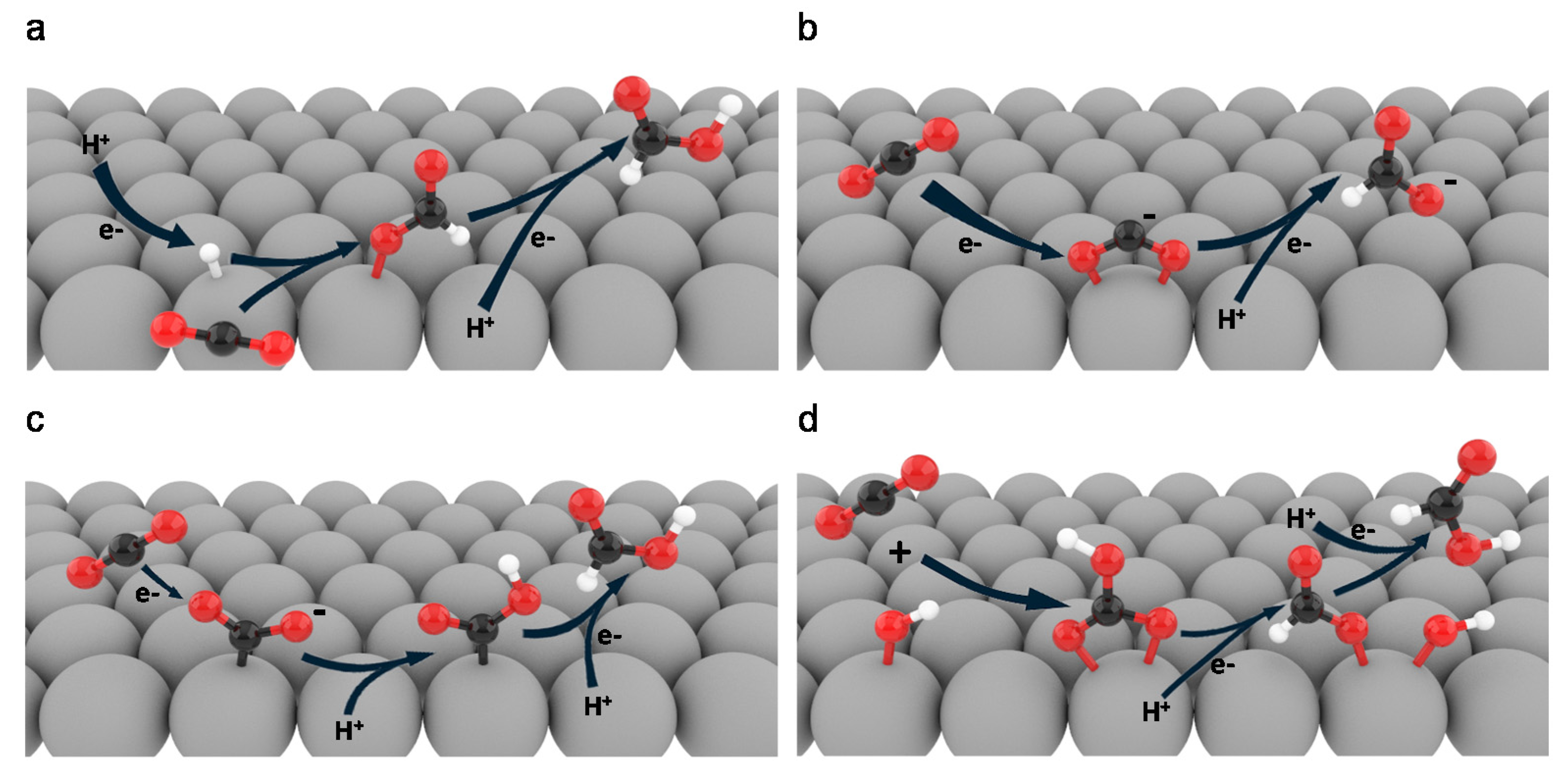
2. Reaction Pathways

The ability of a catalyst to adsorb and desorb specific reaction intermediates determines the main reaction pathway, along with the overpotential that is needed to overcome the energy barrier to that pathway. Therefore, a deep understanding of the CO2RR mechanism will give researchers the necessary knowledge to design more efficient catalysts [34,35]. In this section, we will discuss four reported reaction pathways for HCOOH/HCOO production: (1) CO2 insertion, (2) an O-bound intermediate, (3) a C-bound intermediate, and (4) a bicarbonate intermediate.
The first probable mechanism for HCOOH production is CO2 insertion into the metal-H bond and formation of the *HCOO intermediate (Figure 1a) [36]. HCOOH is subsequently obtained via *HCOO reduction. This mechanism occurs on Pd-based catalysts. The strong hydrogen binding affinity of Pd results in hydrogen absorption into the Pd lattice and the formation of β-phase PdHx, if the Pd catalyst is held at potentials of <0 V vs. RHE [37]. The surface hydride will reduce the CO2 and form the *HCOO intermediate. Formate has been produced by this reaction mechanism at a very low potential of 0 V vs. RHE in HCO3 solutions [38,39].
The second reaction pathway, which involves an O-bound intermediate, starts with the first electron transfer to CO2 and the formation of a weakly adsorbed CO2 radical intermediate (Figure 1b). Formic acid is produced from the transfer of protons and electrons from the reaction between the CO2 radical and proton donors like water, bicarbonate, and hydronium ions [36,40]. Li et al. reported that Sn foil follows this mechanism and can produce formate with an FE of 63.6% and a partial current density of 3.11 mA cm−2 at −1.01 V vs. RHE [41]. Metals such as In, Pb, Hg, Sn, and Bi are reported to follow the O-bound-intermediate pathway due to the easier formation of the *HCOO intermediate compared to *COOH [19,42]. This group produces formate with high selectivity overall, although Sn and In produce a small amount of CO.
In the C-bound-intermediate pathway, the CO2 radical is formed and then bounded to the catalyst surface via the C atom (Figure 1c). The CO2 radical next reacts with H+ to form an adsorbed *COOH. HCOO/HCOOH can then be produced from *COOH. According to Sullivan et al., the *COOH form of the intermediate for HCOOH production is unstable and tends to either decompose into M-H + CO2 or lose OH through a nucleophilic attack to form the M-C = O+ intermediate [43]. However, appropriate metal catalysts can stabilize the *COOH intermediate by an isomerization process shown in (5)–(7) that forms a more stable *HCOO intermediate and ultimately releases HCOO. The number of proposed alternative reactions indicates that reactions will occur in parallel in the majority of systems [40,44].
*COOH (ad) ⇌ *HCOO
*HCOO + e → HCOO (ad)
HCOO (ad) → HCOO (aq)
Cu- and Ru-based catalysts produce formate via the C-bound-intermediate pathway because of their basic natures and because the bond formed by electron transfer from CO2 to unoccupied metal orbitals is stabilized by back-donation from the d orbitals of the metal atom. Those metals are also able to produce other products, such as alcohols or hydrocarbons, depending on the reaction conditions [40,45]. A theoretical report by Yoo et al. stated that Cu(211) can produce formic acid at low overpotentials via the *COOH pathway due to its higher (more positive) limiting potential compared to the *HCOO pathway. Cu-based electrocatalysts have been reported to produce formate as the main product when applied to the anionic membrane of a membrane electrode assembly (MEA) electrolyzer [46]. The same report stated that applying high pressure resulted in formate becoming the main product of the reaction on the Cu catalyst.
The bicarbonate-intermediate pathway starts with a reaction between adsorbed *OH and CO2 to form the adsorbed bicarbonate (CO3H*) species (Figure 1d) [47,48]. The CO3H* intermediate reacts with H+ and receives an electron to form *HCOO and *OH. HCOOH is released after HCOO has reacted with another H+ and received another electron. This reaction pathway has been reported to occur at the Bi–Sn interface with an onset potential of −0.7 V vs. RHE in 0.5 M KHCO3. The FEHCOOH reaches 96% at −1.1 V vs. RHE [47]. PdSnO2 and SnOx surfaces were also reported to produce formate via the bicarbonate-intermediate pathway [49,50]. This reaction mechanism is likely to occur on catalysts with relatively high *OH binding strengths.
The intermediate binding affinity of a catalyst is associated with its product selectivity, the reaction overpotentials, and the mechanism, which implies that catalytic performance can be enhanced by controlling the intermediate binding affinity. In the following sections, we will discuss several strategies in detail, including tailoring the facet, edge, and corner sites of the catalyst and controlling the catalyst composition.
Figure 1. Reaction pathways for HCOOH (HCOO) production. (a) CO2 insertion into a metal-H bond [36]; (b) CO2 to HCOO via O-bound intermediate [36]; (c) CO2 to HCOOH via C-bound intermediate [51,52]; and (d) HCOOH production from CO3H* [47]. Color codes: black, C; red, O; white, H; grey, metals.
Catalysts 10 00859 g001

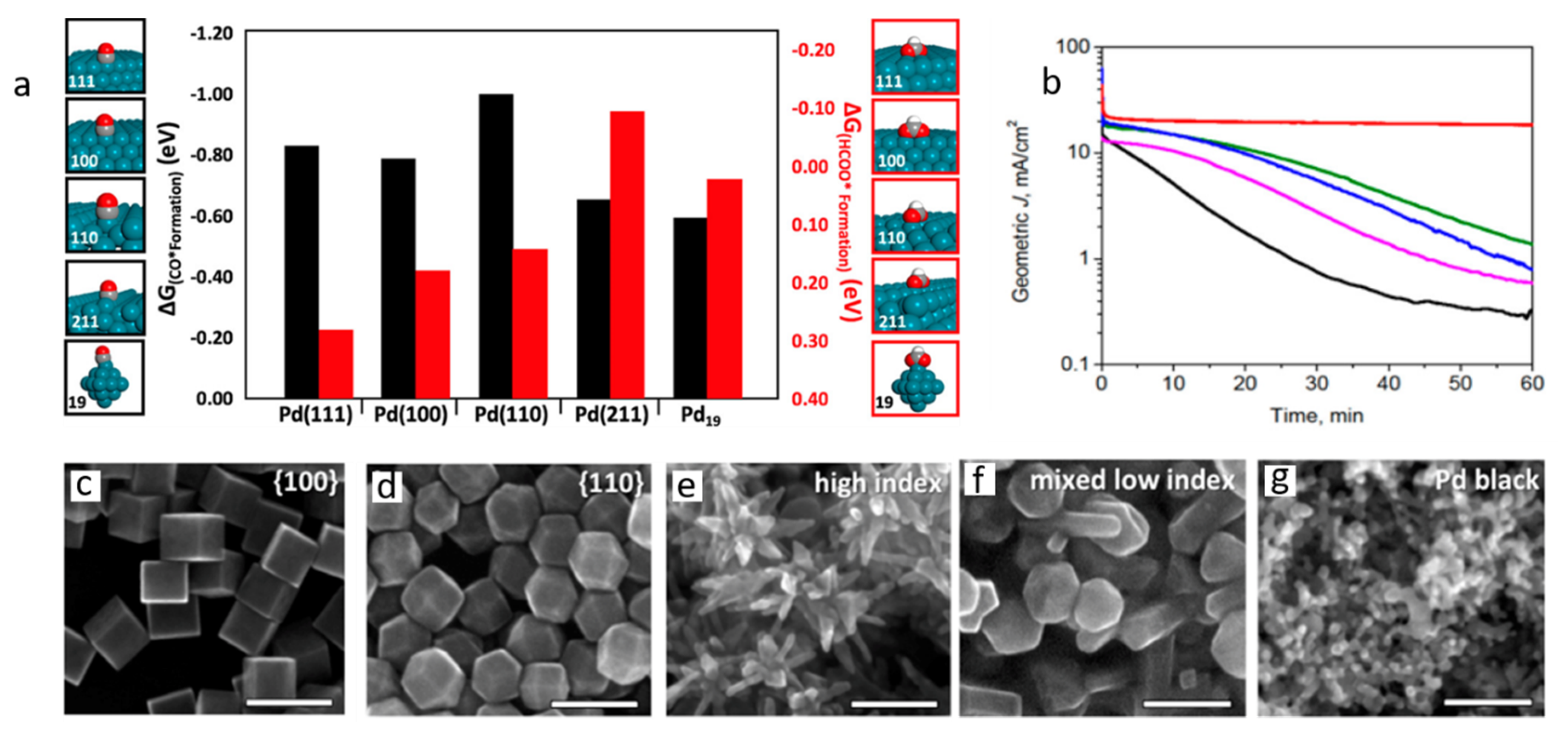
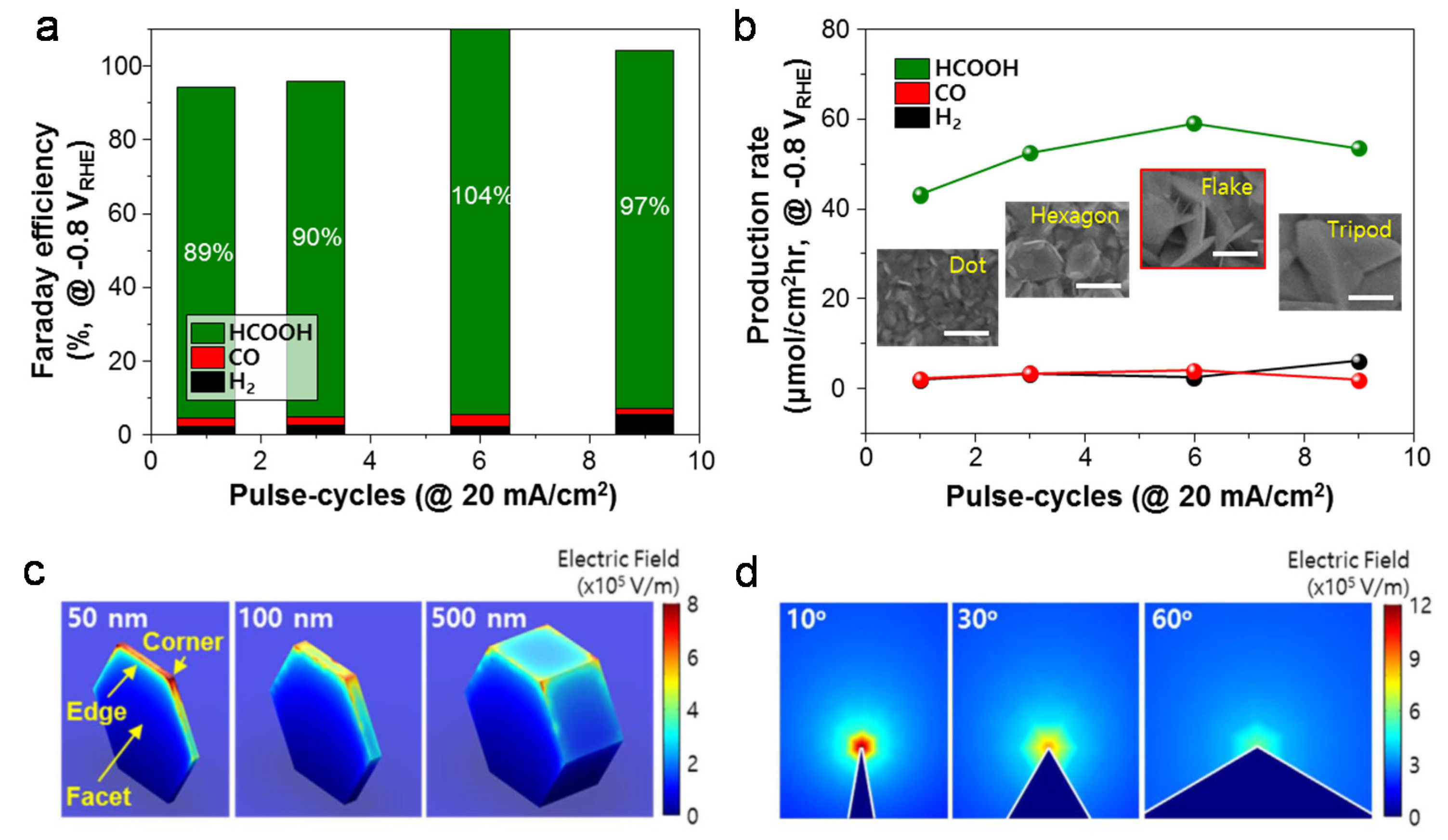
3. Nanostructural Engineering
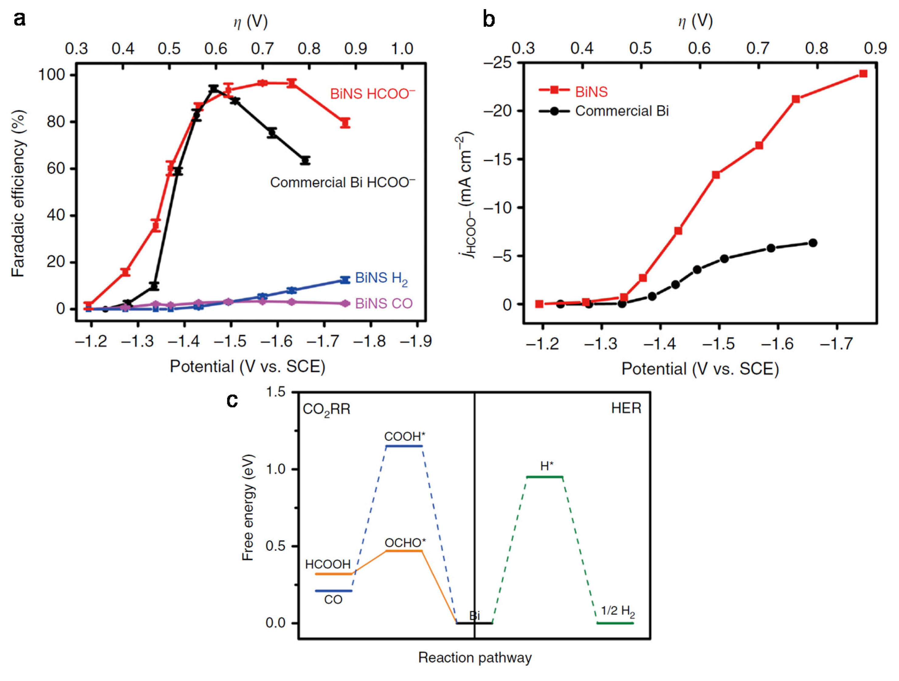
The geometrical features of a catalyst can greatly affect its CO2 electroreduction performance. The exposed high-energy facets, edges, and corners will significantly enhance the catalytic activity towards CO2 reduction [28,31,53,54]. The catalytic activity of a nanostructured catalyst is usually proportional to the number of under-coordinated sites [31]. Sites such as high-index facets have abundant under-coordinated atomic steps and exhibit enhanced catalytic activity compared to low-index nanoparticles [29,53]. Moreover, a large number of edge and corner sites enhances catalytic activity by facilitating a strong electric field at the catalyst surface to ease the adsorption of CO2 [28,31].
Klinkova et al. reported the relationship between surface atom coordination and the catalytic performance of Pd nanoparticles (NPs) in CO2 electroreduction to formate [53]. The authors first conducted density functional theory (DFT) calculations on Pd(111), Pd(110), Pd(100), and Pd(211) surfaces and a Pd19 cluster. As shown in Figure 2a, the authors found that the ∆Gformation of CO* increased from −0.83 eV on Pd(111) to −0.65 eV on Pd(211), while the ∆Gformation of *HCOO decreased from 0.28 eV on Pd(111) to −0.09 eV on Pd(211). Therefore, the formation of *HCOO is made more favorable by incorporating higher-index facets. After obtaining these predictions from the DFT calculations, the authors then synthesized {100} plane-enclosed nanocubes (NCs), {110} plane-enclosed rhombic dodecahedra (RDs), NPs with mixed low-index facets, and branched NPs (BNPs) enclosed by high-index facets. The synthesized NPs are shown in Figure 2c–g. Electrochemical characterization revealed that at the beginning of electrolysis, the total geometric current densities increased from 15 to 22 mA cm−2 at a −0.2 V overpotential. All geometric current densities decreased during the reaction due to CO poisoning of the catalyst surface. The measured rate of decrease of the current density was in agreement with the calculated results in which BNPs, which have the highest-index facets, have the lowest rate of decrease of the current density (Figure 2b).
Kim et al. reported the correlation between the number of edge and corner sites and the electrocatalytic performance of Bi NPs [31]. Sharper Bi nanoflakes had greater numbers of edge and corner sites. The authors used the electrodeposition pulse current (PC) method to synthesize nanostructured Bi nanoflakes. Figure 3a,b shows the samples fabricated with between 1 and 9 pulse cycles at 20 mA cm−2. The samples at 1 and 3 pulse cycles showed FEs of 89% and 90%, respectively, and were not perfectly converted to Bi nanoflakes. The sample at 6 pulse cycles was completely converted to Bi nanoflakes and achieved an FE of over 100%. However, the sample at 9 pulse cycles showed a decrease in FE to 97% because Bi layers were covering the edge and corner sites, transforming the structure into a tripod shape. The prospects of electrostatic field intensification at the edges and corners were explored using a COMSOL Multiphysics simulation. A hexagonal Bi nanostructure was used as a representative three-dimensional structure with an edge length of 500 nm at various thicknesses (Figure 3c). Reducing the thickness from 500 to 10 nm enhanced the electrostatic electric field intensities at the edge and corner 3- and 5-fold, respectively. A two-dimensional Bi nanostructure was simulated to investigate the effect of sharpening the corners (Figure 3d); reducing the angle from 70 to 5° enhanced the electric field 2.5-fold. The electric field affects the overall reaction rate by increasing the local concentration of K+, which enhances CO2 adsorption by lowering the free energy for the adsorption of intermediates [28,31].
Two-dimensional materials were reported to have higher selectivity and intrinsic activity than bulk materials because of the high exposure of the active facets. Additionally, these materials have high surface areas compared to bulk materials [55,56,57,58]. For example, Han et al. reported ultrathin Bi nanosheets (NSs; BiNS) with an exceptional FE of almost 100% and a larger partial current density than that of commercial Bi (Figure 4a,b) [56]. The ultrathin BiNS were prepared by in situ topotactic transformations of BiOI NSs. To support the study, DFT calculations were conducted via the computational hydrogen electrode methodology. These simulations were performed on the Bi(001) facet because it was the predominantly exposed facet of the BiNS (Figure 4c). The CO2 reduction to formate was initiated by protonation of the C atom to form the *HCOO intermediate in a mildly endothermic reaction (+0.49 eV). The second proton-coupled electron transfer to HCOO was an exothermic reaction (−0.17 eV). Ultimately, HCOO was spontaneously released from the catalyst. Protonation of the O atom to form COOH*, which was the intermediate for CO production, had a significantly higher energy barrier (+1.16 eV). The energy barrier for H adsorption into Bi(001) was also too high (+0.95 eV). The production of formate on Bi(001) was accordingly more favorable than the evolution of CO and H2.
Grain boundaries (GBs) enhance the activity of catalysts by providing highly active reaction sites [59]. Feng et al. pioneered the quantitative correlation analysis between the density of GBs and the catalytic activity of catalysts [60]. They found a linear correlation between the GB surface density and the specific activity for CO2RRs on vapor-deposited Au NPs on carbon nanotubes. Li et al. reported the catalytic performance of Bi NPs/Bi2O3 NSs with abundant GBs. The catalyst, which was obtained by facile hydrothermal synthesis, was compared to low-GB-density Bi NSs/Bi2O3 NSs. High-resolution transmission electron microscopy (HRTEM) images of the catalysts have shown the GB density difference between the two catalysts (Figure 5a,b). The Bi NPs/Bi2O3 NSs exhibited a superior catalytic performance to that of Bi NSs/Bi2O3 NSs (Figure 5c,d). The Bi NPs/Bi2O3 NSs also showed a higher formate partial current density of 24.4 mA cm−2, an FEHCOOH of >90% over a broad potential range, and over 24 h of catalyst durability.

4. Composition

4.1. Bimetallic Compounds

Controlling the composition of bimetallic compounds is an important strategy for tuning the electronic behavior of nanomaterials to enhance their selectivity and catalytic activity [24,62,63]. Bimetallic compounds can change the electronic structure of a catalyst, which affects the intermediate binding energy, which in turn controls the overall reaction pathway [27]. Many previously reported bimetallic compounds have shown enhanced catalytic activity compared to the corresponding pristine-metal-based catalysts, such as Ag–Sn [63], Cu–Bi [24,64], In–Sn [41], Sn–Cu [65,66], Pd–Ni [67], and Bi–Sn [47].
Wen et al. synthesized a Bi–Sn catalyst that had better selectivity for formate than a well-known Sn catalyst [47]. As-synthesized Bi–Sn on carbon fabric (CF) exhibited a dramatic current increase in CO2-purged electrolyte (Figure 6a). At −1.14 V vs. RHE, Bi–Sn/CF had a superior FEHCOOH of 94% ± 2% compared to Sn/CF, which had an FEHCOOH of 78% ± 2% (Figure 6b). To support the experimental data, the authors conducted periodic DFT calculations on the reaction pathways to CO and HCOO from the adsorption of CO3H*. As shown in Figure 6c,d, the binding energy differences between the *COOH and *HCOO intermediates (∆E1) on Sn(101) and Bi–Sn(101) surfaces were 0.55 and 0.81 eV, respectively. The binding energy differences between the CO* and HCOOH* intermediates (∆E2) on Sn(101) and Bi–Sn(101) surfaces were 0.43 and 0.85 eV, respectively. The larger ∆E of the Bi–Sn catalyst indicates greater selectivity for formate, which agrees with the experimental results. In summary, tuning the composition of bimetallic compounds can help with the optimization of the intermediate binding energy of the catalysts to achieve higher catalytic selectivity and performance.

4.2. Doping Materials

Doping is another strategy to enhance the catalytic activities of electrocatalysts. The dopant affects the electronic properties of the host [66,68,69], which may allow the binding energy for a particular intermediate to be designed to facilitate the desired reaction pathway [70].
Pd-based catalysts are known to have almost zero overpotential to activate CO2RRs to formate but also have a parallel CO pathway that competes with and may even deactivate formate production [37,71]. Bei Jiang et al. successfully increased the selectivity of a Pd-based catalyst for the production of formate with a high CO tolerance by doping the catalyst with boron [72]. The authors compared Pd–B/C to a control sample of Pd/C. The FECO increased as the potential became more negative on Pd-based catalysts. However, the FECO of Pd–B/C was much lower than that of Pd/C at any given potential (Figure 7a). The FEHCOOH of Pd–B/C reached a maximum value of 70% at −0.5 V vs. RHE, but Pd/C had an FEHCOOH of only 4.8% at the same potential. Furthermore, Pd/C had an FEHCOOH close to zero at potentials lower than −0.7 V vs. RHE, whereas the Pd–B/C catalyst had an FEHCOOH of 15–30% under those conditions. To gain a greater understanding of the promoting effect of B doping on formate production on Pd, the authors conducted DFT calculations on Pd(111) with and without B doping. Figure 7c,d present the Gibbs free energy diagrams for the intermediates of the CO and HCOOH pathways. The CO production pathway has a lower energy barrier than the HCOOH production pathway on the Pd(111) surface. In contrast, HCOOH production has the lower energy barrier on Pd(111)−4B, making it the more favorable pathway. The effects of B doping on the subsurface of the Pd lattice interstices include unique electronic behavior owing to partial electron transfer between Pd and B as well as a downshifted d-band center for the surface Pd. Thus, the new electronic structure leads to a more negative adsorption energy for *HCOO than for *COOH.
A dopant can also affect the reaction rate by interacting with hydrated cations. For example, Ma et al. proposed that [73] the hydrated potassium cation (K+(H2O)n) could form networks with the Sδ− anions of sulfur-doped indium in the double layer through non-covalent Coulomb interactions (Figure 8a). These interactions can enhance the dissociation of H2O to form the adsorbed hydrogen intermediate (*H) that is responsible for the formation of the *HCOO intermediate, which is the precursor of formic acid. The authors synthesized S2–In2O3-derived In/C (4.9 mol % S), along with a control sample of S0–In2O3-derived In/C (0 mol% S). The experimental results showed an enhancement of catalytic activity in the presence of S, with FEHCOOH values of 89% and 93% and current densities of 37 and 84 mA cm−2 (−0.98 V vs. RHE) for S0–In2O3-derived In/C and S2–In2O3-derived In/C, respectively (Figure 8b). The DFT calculation results indicated that the presence of S on the In surface decreased the Gibbs free energies for *HCOO and HCOOH* in the HCOOH pathway*HCOO from 0.29 to −0.16 eV and from 0.67 to 0.10 eV, respectively (Figure 8c). The Gibbs free energy calculation for H* formation showed that the H* formation energy is much lower on the S sites of S–In (0.21 eV) than it is on either the In sites of S–In (0.69 eV) or on pure In (0.82 eV) (Figure 8d). These calculated results are in good agreement with the experimental results.

5. Mass Transport

The catalytic properties of CO2RRs depend on the nature of the catalyst and the local concentrations of the reactants at the catalyst interface. The CO2RR to formate has been reported to be the first order with respect to the CO2 concentration [37,51]. This means that the rate of formate production is limited by the CO2 concentration but could be greatly enhanced by the mass transport control. Therefore, the mass transport control of CO2 in CO2RRs is another crucial aspect of achieving good catalytic performance. Further, substantial hydrogen evolution can proceed from various proton-donating species, such as bicarbonate and water, thereby lowering the CO2RR selectivity [21]. Controlling the local pH at the catalyst surface can affect the chemical equilibria of proton-donating species and, therefore, the HER rate. In this section, we discuss mass transport control strategies that are relevant for CO2RRs: (i) tuning the local pH at the catalyst–electrolyte interface; (ii) using high-pressure reactors; and (iii) employing three-phase-boundary electrodes and reactors.

5.1. Local pH Control

During electrolysis, the local pH near the electrode surface tends to be higher than that of the bulk region due to OH production from both the CO2RR and the HER [74,75]. The increase in local pH will change the concentrations of proton-donating species, which is beneficial for inhibiting the HER. However, a high local pH can also decrease the CO2 concentration at the electrode surface because of the equilibria between CO2, HCO3, and CO32−, which might lead to a low CO2RR partial current density (Figure 9) [12,13,76,77]. Thus, the local pH value should be targeted to suppress hydrogen evolution while maintaining the CO2 concentration near the electrode. Luo et al. reported the enhanced CO2RR performance of porous-structured-Zn (P-Zn) owing to an enlarged surface area and a strengthened local pH effect [78]. Upon comparing Zn foil to P-Zn, the enlarged surface area of P-Zn led to a 10-fold higher total current density, and the local pH effect reduced the HER rate. The buffering capacity of the electrolyte also has an important role in controlling the local pH. Ma et al. evaluated the CO2RR performance of a flat Ag electrocatalyst in 0.1 M K2HPO4, 0.1 M KHCO3, and 0.1 M KClO4 to identify the correlation between the electrolyte buffering capacity (K2HPO4 > KHCO3 > KClO4) and the local pH effect [79]. As the buffering capacity decreased, the FE for the CO2RR increased because a lower buffering capacity allows the high local pH to be maintained, thereby suppressing the HER.

5.2. High-Pressure Reactor

According to Henry’s law, increasing the partial pressure of the CO2 can increase the concentration of the dissolved CO2. One of the pioneering efforts by Todoroki et al. in this regard was an electrochemical reduction of CO2 at a pressure of 60 atm, which achieved an FEHCOOH of nearly 100% and a large current density of 200 mA cm−2 [80]. Komatsu et al. reported that the FEHCOOH rose significantly as the partial pressure of CO2 increased on Cu catalysts [46]. These results indicated that an elevated CO2 partial pressure would improve the rate of HCOOH formation by increasing the solubility of CO2 in aqueous solutions. However, a recent report by Ramdin et al. found that CO2 pressures of over 40 bar while using a bipolar membrane (BPM) had several disadvantages, including formate crossover through the BPM that decreases the FEHCOOH by reoxidation of the as-synthesized formate on the anode. Another major disadvantage of this technique is the significant pH drop caused by the high concentration of CO2 in the solution, which favors hydrogen evolution [81]. Thus, to obtain excellent performance in a high-pressure reactor, it is preferable to use an ion-exchange membrane with a low product crossover rate and to maintain the pH value.

5.3. Three-Phase Boundary

Despite the significant progress that has been made, there are still limitations for CO2 mass transport that set the upper limit of current density at tens of milliamperes per square centimeter [82,83]. Therefore, utilizing a gas diffusion electrode (GDE), which was originally developed for fuel cell applications, for direct CO2 delivery to the catalyst surface using water vapor as a carrier was proposed [84]. An article by Delafontaine et al. reported that in a conventional H-type cell, the concentration of CO2 in aqueous solution was 0.038 M. Direct delivery of humidified CO2 to the flow cell resulted in a modest increase in the relative saturated CO2 concentration to 0.041 M. In the same article, the diffusion coefficient of aqueous CO2 was reported to be as low as 0.0016 mm2 s−1 in CO2-saturated 0.1 M KHCO3 [85,86]. Delivering humidified gaseous CO2 with a GDE dramatically increased the CO2 diffusion coefficient 10,000-fold to 16 mm2 s−1 (Figure 10a) [86]. The ease with which gaseous CO2 reached the catalyst resulted in a high CO2 availability and a subsequent increase in the CO2RR partial current density. As shown in Figure 10a, the GDE system is composed of a diffusion medium and a porous catalyst layer [87]. The diffusion medium is usually a hydrophobic carbon layer consisting of a macroporous carbon fiber layer and a microporous carbon powder layer. The diffusion medium serves many purposes, such as providing a porous medium through which CO2 can diffuse to the catalyst layer, mechanically supporting the catalyst layer, and providing conductive pathways for the flow of electrons. Commercial diffusion media are usually treated with polytetrafluoroethylene (PTFE) to provide hydrophobicity. An ideal GDE remains hydrophobic throughout the process to prevent the electrolyte from leaking into the gas chamber. The catalyst is deposited on the microporous layer (MPL) to form the active catalytic site. The catalyst particles are usually mixed with a binder to hold the particles together and provide ionic conductivity.
Del Castillo et al. reported the performance of an Sn/C-GDE using a membrane reactor [89]. Toray paper (TGP-H-90) was used as the carbonaceous support. The MPL was formed from Vulcan XC-72R and PTFE (40:60) that was air-brushed onto the carbonaceous support and sintered at 350 °C for 30 min. The catalyst ink consisted of Sn NPs and a Nafion solution (70:30) and was sprayed onto the MPL to achieve a Sn loading of 0.75 mg cm−2. The Sn/C-GDE catalyst reached 70% FE at a current density of 150 mA cm−2.
The MEA reactor is a common electrochemical flow cell for CO2RRs (Figure 10a) [85]. In a traditional batch-type cell, the ions must diffuse in the bulk electrolyte to reach the membrane. This kind of system has a relatively high diffusion resistance, and the reactant availability in the counter electrode is accordingly limited. In contrast, in an MEA reactor, the membrane is sandwiched between the cathode and anode to directly transfer ions between the electrodes (e.g., H+ transfer between the anode and cathode). Consequently, the current density is markedly increased relative to traditional flow cells.
Another notable flow cell design is the microfluidic cell system proposed by the Kenis group (Figure 10b) [90,91]. This reactor has a thin channel of less than 1 mm through which the electrolyte flows between the anode and cathode [85]. CO2 gas is supplied to the electrocatalyst through the GDL and reacts at the three-phase interface to form the product. A polymer electrolyte membrane (PEM) is not needed for a gaseous-product-type reactor. This reactor relies on the diffusion of the gaseous product to separate the oxidation and reduction products (Figure 10c, top), avoiding the use of high-cost membranes [85]. The microchannel enables laminar flow of the electrolyte, which eliminates the need for a membrane but still allows ionic transport between the electrodes. However, a PEM is still needed for liquid-product-type microfluidic cells to prevent product crossover (Figure 10c, bottom). Recently, Deng et al. reported the performance of a metal–organic framework (MOF)-derived carbon-nanorod-encapsulated bismuth oxide catalyst in both an H-type cell and a microfluidic cell system. Catalysis using an H-type cell resulted in an optimal FEHCOOH of 92% and a partial current density of 7.5 mA cm−2 at −0.9 V vs. RHE. As predicted, the microfluidic cell system exhibited a dramatic performance increase compared to the H-type cell, including a current density of 200 mA cm−2 at −1.1 V vs. RHE. Overall, these results indicate that the barrier of low CO2 solubility has been tackled by using GDL-based three-phase-boundary reactors.

6. Reported Performances

We have summarized the reported performances in terms of the strategies for enhancing catalytic performance to provide insight into the effects of these strategies (Figure 11) [10,47,53,61,72,92,93]. The results of the strategy of tailoring the exposed facets can be seen in the difference between Pd catalysts with low-index and high-index facets reported by Klinkova et al. The Pd BNPs with high-index facets have an almost identical FEHCOOH and a 1.5-fold larger formate partial current density compared to the low-index-facet Pd NCs. High-density-GB Bi/Bi2O3 (HDGB) had an FEHCOOH of almost 100%, whereas the FEHCOOH of low-density-GB Bi/Bi2O3 (LDGB) was 87.5%. The formate partial current density of HDGB was enhanced almost 1.6-fold compared to that of LDGB. The effect of using bimetallic materials can be seen in the performances of Sn/CF and Bi–Sn/CF. The bimetallic Bi–Sn/CF had an almost 20% higher FEHCOOH and a nearly 3-fold increase in formate partial current density compared to Sn/CF. The FEHCOOH enhancement can be attributed to an interaction between Bi and Sn that modified the electronic structure of the catalyst in a way that increased the intermediate selectivity, but the improved formate partial current density was because of the nanostructuring effect where Bi–Sn/CF had greater active site exposure. The effect of dopants can be seen in the difference between the Pd/C and Pd–B/C catalysts. Boron insertion resulted in an enlargement within the lattice and a partial electron transfer between B and Pd. These phenomena altered the catalyst electronic structure, which increased the formate selectivity almost 15-fold to 69.3% on Pd–B/C. A two-dimensional SnO2 material showed a higher formate selectivity of 85% compared to bulk Sn foil and had an FEHCOOH of 63%. The current density of two-dimensional SnO2 also increased to 14.75 mA cm−2 from the 3.11 mA cm−2 of bulk Sn foil at −1.01 V vs. RHE. Moreover, the application of SnO2 NSs to GDEs successfully enhanced the formate partial current density from 14.75 mA cm−2 on SnO2 NSs to an incredibly high 471 mA cm−2 on the SnO2 GDE.
Overall, optimizing the electronic structure of the electrocatalyst can enhance the formate selectivity, and the use of GDEs is the finest strategy for increasing the formate partial current density. However, achieving a low overpotential along with a high FEHCOOH and a fast formate production rate remains a challenge. The reported Pd-based catalysts exhibited low overpotentials, but the stability issue raised by CO poisoning must be addressed for further optimization of catalytic performance. Furthermore, even though Bi- and Sn-based GDEs have resulted in higher current densities by orders of magnitude, new catalyst design strategies are required to reduce the overpotential to close to the equilibrium potential of formate production.

7. Conclusions

Researchers have made efforts to develop new catalysts and extrinsically enhance catalytic systems. However, the inert nature of CO2, the low solubility of CO2 in aqueous solutions, and the slow mass transport of CO2 result in the CO2RR system for formate production still having low selectivity, high overpotentials, and limited formate partial current density. Several strategies have been employed to address these challenges. Tailoring the binding affinity of a catalyst for a key intermediate was reported to enhance the selectivity and reduce the overpotential of the catalyst. This tailoring can be achieved in several ways, including exposing the high-energy facet, edge, and corner sites and controlling the composition of the catalyst. Attempts have been made to address the low CO2 solubility and slow mass transport of CO2 onto the catalyst surface by optimizing the local pH at the catalyst surface, using a high-pressure reactor to increase the CO2 solubility, and employing a GDE to directly transport gaseous CO2 to the active sites. However, the high-pressure environment makes the product cross over through the ion transport membrane towards the anodic side of the reactor, which depresses formate production. The loss of hydrophobicity in the GDE during electrolysis also decreases the CO2 concentration on the catalyst surface owing to the electrolyte flooding the gas diffusion medium. These issues must be addressed in future studies in addition to stabilizing the catalyst. Machine learning based on DFT calculations is expected to accelerate the identification of efficient catalysts satisfying the requirements of low overpotential with high selectivity and stability. We believe that the minimum requirements for technoeconomic feasibility of this pathway to formate production can be achieved via the combined approaches of catalyst development and broader system-level strategies.

Author Contributions

Writing—original draft preparation, M.A.; Writing—review and editing, C.W.L.; supervision, C.W.L. All authors have read and agreed to the published version of the manuscript.

Funding

This work was supported by the National Research Foundation of Korea (NRF) Grant funded by the Korean Government (MSIT; NRF-2020R1C1C1010963 and NRF-2016R1A5A1012966).

Acknowledgments

In this section you can acknowledge any support given that is not covered by the author contribution or funding sections. This may include administrative and technical support, or donations in kind (e.g., materials used for experiments).

Conflicts of Interest

The authors declare no conflict of interest.

References

  1. Karl, T.R.; Trenberth, K.E. Modern Global Climate Change. Science 2003, 302, 1719–1723. [Google Scholar] [CrossRef] [PubMed] [Green Version]
  2. Pachauri, R.K.; Meyer, L.A. IPCC, 2014: Climate Change 2014: Synthesis Report. Contribution of Working Groups I, II and III to the Fifth Assessment Report of the Intergovernmental Panel on Climate Change; IPCC: Geneva, Switzerland, 2015. [Google Scholar]
  3. King, A.D.; Karoly, D.J.; Henley, B.J. Australian climate extremes at 1.5 °C and 2 °C of global warming. Nat. Clim. Chang. 2017, 7, 412–416. [Google Scholar] [CrossRef]
  4. Lee, C.W.; Cho, N.H.; Nam, K.T.; Hwang, Y.J.; Min, B.K. Cyclic two-step electrolysis for stable electrochemical conversion of carbon dioxide to formate. Nat. Commun. 2019, 10, 1–8. [Google Scholar] [CrossRef] [PubMed] [Green Version]
  5. Prakash, G.K.S.; Viva, F.A.; Olah, G.A. Electrochemical reduction of CO2 over Sn-Nafion® coated electrode for a fuel-cell-like device. J. Power Sources 2013, 223, 68–73. [Google Scholar] [CrossRef]
  6. Bagotzky, V.S.; Osetrova, N.V. Electrochemical reduction of carbon dioxide. Russ. J. Electrochem. 1995, 31, 409–425. [Google Scholar]
  7. Agarwal, A.S.; Zhai, Y.; Hill, D.; Sridhar, N. The Electrochemical Reduction of Carbon Dioxide to Formate/Formic Acid: Engineering and Economic Feasibility. ChemSusChem 2011, 4, 1301–1310. [Google Scholar] [CrossRef]
  8. Loges, B.; Boddien, A.; Gärtner, F.; Junge, H.; Beller, M. Catalytic Generation of Hydrogen from Formic acid and its Derivatives: Useful Hydrogen Storage Materials. Top. Catal. 2010, 53, 902–914. [Google Scholar] [CrossRef]
  9. Fellay, C.; Yan, N.; Dyson, P.J.; Laurenczy, G. Selective Formic Acid Decomposition for High-Pressure Hydrogen Generation: A Mechanistic Study. Chem. A Eur. J. 2009, 15, 3752–3760. [Google Scholar] [CrossRef]
  10. Xiang, H.; Miller, H.A.; Bellini, M.; Christensen, H.; Scott, K.; Rasul, S.; Yu, E.H. Production of formate by CO2 electrochemical reduction and its application in energy storage. Sustain. Energy Fuels 2019, 4, 277–284. [Google Scholar] [CrossRef]
  11. Lee, C.W.; Yang, K.D.; Nam, D.H.; Jang, J.H.; Cho, N.H.; Im, S.W.; Nam, K.T. Defining a Materials Database for the Design of Copper Binary Alloy Catalysts for Electrochemical CO2 Conversion. Adv. Mater. 2018, 30, 1–18. [Google Scholar] [CrossRef]
  12. Lee, C.W.; Kim, C.; Min, B.K. Theoretical insights into selective electrochemical conversion of carbon dioxide. Nano Converg. 2019, 6. [Google Scholar] [CrossRef] [PubMed]
  13. Nitopi, S.; Bertheussen, E.; Scott, S.B.; Liu, X.; Engstfeld, A.K.; Horch, S.; Seger, B.; Stephens, I.E.L.; Chan, K.; Hahn, C.; et al. Progress and Perspectives of Electrochemical CO2 Reduction on Copper in Aqueous Electrolyte. Chem. Rev. 2019, 119, 7610–7672. [Google Scholar] [CrossRef] [PubMed] [Green Version]
  14. Rumayor, M.; Dominguez-Ramos, A.; Perez, P.; Irabien, A. A techno-economic evaluation approach to the electrochemical reduction of CO2 for formic acid manufacture. J. CO2 Util. 2019, 34, 490–499. [Google Scholar] [CrossRef]
  15. Rumayor, M.; Dominguez-Ramos, A.; Irabien, A. Formic Acid Manufacture: Carbon Dioxide Utilization Alternatives. Appl. Sci. 2018, 8, 914. [Google Scholar] [CrossRef] [Green Version]
  16. Na, J.; Seo, B.; Kim, J.; Lee, C.W.; Lee, H.; Hwang, Y.J.; Min, B.K.; Lee, D.K.; Oh, H.S.; Lee, U. General technoeconomic analysis for electrochemical coproduction coupling carbon dioxide reduction with organic oxidation. Nat. Commun. 2019, 10. [Google Scholar] [CrossRef]
  17. Verma, S.; Kim, B.; Molly Jhong, H.-R.; Ma, S.; Kenis, P.J.A. A Gross-Margin Model for Defining Technoeconomic Benchmarks in the Electroreduction of CO2. ChemSusChem 2016, 9, 1972–1979. [Google Scholar] [CrossRef]
  18. Zhang, W.; Hu, Y.; Ma, L.; Zhu, G.; Wang, Y.; Xue, X.; Chen, R.; Yang, S.; Jin, Z. Progress and Perspective of Electrocatalytic CO2 Reduction for Renewable Carbonaceous Fuels and Chemicals. Adv. Sci. 2018, 5, 1700275. [Google Scholar] [CrossRef]
  19. Yoo, J.S.; Christensen, R.; Vegge, T.; Nørskov, J.K.; Studt, F. Theoretical Insight into the Trends that Guide the Electrochemical Reduction of Carbon Dioxide to Formic Acid. ChemSusChem 2016, 9, 358–363. [Google Scholar] [CrossRef]
  20. Medina-Ramos, J.; DiMeglio, J.L.; Rosenthal, J. Efficient Reduction of CO2 to CO with High Current Density Using in Situ or ex Situ Prepared Bi-Based Materials. J. Am. Chem. Soc. 2014, 136, 8361–8367. [Google Scholar] [CrossRef] [Green Version]
  21. Nguyen, D.L.T.; Lee, C.W.; Na, J.; Kim, M.C.; Tu, N.D.K.; Lee, S.Y.; Sa, Y.J.; Won, D.H.; Oh, H.S.; Kim, H.; et al. Mass Transport Control by Surface Graphene Oxide for Selective CO Production from Electrochemical CO2 Reduction. Acs Catal. 2020, 10, 3222–3231. [Google Scholar] [CrossRef]
  22. Lee, C.W.; Cho, N.H.; Im, S.W.; Jee, M.S.; Hwang, Y.J.; Min, B.K.; Nam, K.T. New challenges of electrokinetic studies in investigating the reaction mechanism of electrochemical CO2 reduction. J. Mater. Chem. A 2018, 6, 14043–14057. [Google Scholar] [CrossRef]
  23. Medford, A.J.; Vojvodic, A.; Hummelshøj, J.S.; Voss, J.; Abild-Pedersen, F.; Studt, F.; Bligaard, T.; Nilsson, A.; Nørskov, J.K. From the Sabatier principle to a predictive theory of transition-metal heterogeneous catalysis. J. Catal. 2015, 328, 36–42. [Google Scholar] [CrossRef] [Green Version]
  24. Hoffman, Z.B.; Gray, T.S.; Xu, Y.; Lin, Q.; Gunnoe, T.B.; Zangari, G. High Selectivity Towards Formate Production by Electrochemical Reduction of Carbon Dioxide at Copper–Bismuth Dendrites. ChemSusChem 2019, 12, 231–239. [Google Scholar] [CrossRef] [PubMed]
  25. Deng, Y.; Huang, Y.; Ren, D.; Handoko, A.D.; Seh, Z.W.; Hirunsit, P.; Yeo, B.S. On the Role of Sulfur for the Selective Electrochemical Reduction of CO2 to Formate on CuSx Catalysts. Acs Appl. Mater. Interfaces 2018, 10, 28572–28581. [Google Scholar] [CrossRef]
  26. Lee, C.W.; Shin, S.J.; Jung, H.; Nguyen, D.L.T.; Lee, S.Y.; Lee, W.H.; Won, D.H.; Kim, M.G.; Oh, H.S.; Jang, T.; et al. Metal-Oxide Interfaces for Selective Electrochemical C-C Coupling Reactions. Acs Energy Lett. 2019, 4, 2241–2248. [Google Scholar] [CrossRef]
  27. He, J.; Johnson, N.J.J.; Huang, A.; Berlinguette, C.P. Electrocatalytic Alloys for CO2 Reduction. ChemSusChem 2018, 11, 48–57. [Google Scholar] [CrossRef]
  28. Saberi Safaei, T.; Mepham, A.; Zheng, X.; Pang, Y.; Dinh, C.-T.; Liu, M.; Sinton, D.; Kelley, S.O.; Sargent, E.H. High-Density Nanosharp Microstructures Enable Efficient CO2 Electroreduction. Nano Lett. 2016, 16, 7224–7228. [Google Scholar] [CrossRef]
  29. Lee, H.-E.; Yang, K.D.; Yoon, S.M.; Ahn, H.-Y.; Lee, Y.Y.; Chang, H.; Jeong, D.H.; Lee, Y.-S.; Kim, M.Y.; Nam, K.T. Concave Rhombic Dodecahedral Au Nanocatalyst with Multiple High-Index Facets for CO2 Reduction. Acs Nano 2015, 9, 8384–8393. [Google Scholar] [CrossRef]
  30. Yang, D.-R.; Liu, L.; Zhang, Q.; Shi, Y.; Zhou, Y.; Liu, C.; Wang, F.-B.; Xia, X.-H. Importance of Au nanostructures in CO2 electrochemical reduction reaction. Sci. Bull. 2020, 65, 796–802. [Google Scholar] [CrossRef]
  31. Kim, S.; Dong, W.J.; Gim, S.; Sohn, W.; Park, J.Y.; Yoo, C.J.; Jang, H.W.; Lee, J.L. Shape-controlled bismuth nanoflakes as highly selective catalysts for electrochemical carbon dioxide reduction to formate. Nano Energy 2017, 39, 44–52. [Google Scholar] [CrossRef]
  32. Lamaison, S.; Wakerley, D.; Blanchard, J.; Montero, D.; Rousse, G.; Mercier, D.; Marcus, P.; Taverna, D.; Giaume, D.; Mougel, V.; et al. High-Current-Density CO2-to-CO Electroreduction on Ag-Alloyed Zn Dendrites at Elevated Pressure. Joule 2020, 4, 395–406. [Google Scholar] [CrossRef]
  33. Kopljar, D.; Inan, A.; Vindayer, P.; Wagner, N.; Klemm, E. Electrochemical reduction of CO2 to formate at high current density using gas diffusion electrodes. J. Appl. Electrochem. 2014, 44, 1107–1116. [Google Scholar] [CrossRef]
  34. Liu, H.; Zhu, Y.; Ma, J.; Zhang, Z.; Hu, W. Recent Advances in Atomic-Level Engineering of Nanostructured Catalysts for Electrochemical CO2 Reduction. Adv. Funct. Mater. 2020, 30, 1910534. [Google Scholar] [CrossRef]
  35. Lee, C.W.; Cho, N.H.; Yang, K.D.; Nam, K.T. Reaction Mechanisms of the Electrochemical Conversion of Carbon Dioxide to Formic Acid on Tin Oxide Electrodes. ChemElectroChem 2017, 4, 2130–2136. [Google Scholar] [CrossRef]
  36. Kortlever, R.; Shen, J.; Schouten, K.J.P.; Calle-Vallejo, F.; Koper, M.T.M. Catalysts and Reaction Pathways for the Electrochemical Reduction of Carbon Dioxide. J. Phys. Chem. Lett. 2015, 6, 4073–4082. [Google Scholar] [CrossRef] [PubMed]
  37. Min, X.; Kanan, M.W. Pd-Catalyzed Electrohydrogenation of Carbon Dioxide to Formate: High Mass Activity at Low Overpotential and Identification of the Deactivation Pathway. J. Am. Chem. Soc. 2015, 137, 4701–4708. [Google Scholar] [CrossRef] [PubMed]
  38. Podlovchenko, B.I.; Kolyadko, E.A.; Lu, S. Electroreduction of carbon dioxide on palladium electrodes at potentials higher than the reversible hydrogen potential. J. Electroanal. Chem. 1994, 373, 185–187. [Google Scholar] [CrossRef]
  39. Stalder, C.J.; Chao, S.; Wrighton, M.S. Electrochemical reduction of aqueous bicarbonate to formate with high current efficiency near the thermodynamic potential at chemically derivatized electrodes. J. Am. Chem. Soc. 1984, 106, 3673–3675. [Google Scholar] [CrossRef]
  40. Chaplin, R.P.S.; Wragg, A.A. Effects of process conditions and electrode material on reaction pathways for carbon dioxide electroreduction with particular reference to formate formation. J. Appl. Electrochem. 2003, 33, 1107–1123. [Google Scholar] [CrossRef]
  41. Lai, Q.; Yang, N.; Yuan, G. Highly efficient In–Sn alloy catalysts for electrochemical reduction of CO2 to formate. Electrochem. Commun. 2017, 83, 24–27. [Google Scholar] [CrossRef]
  42. Lee, C.W.; Hong, J.S.; Yang, K.D.; Jin, K.; Lee, J.H.; Ahn, H.Y.; Seo, H.; Sung, N.E.; Nam, K.T. Selective Electrochemical Production of Formate from Carbon Dioxide with Bismuth-Based Catalysts in an Aqueous Electrolyte. Acs Catal. 2018, 8, 931–937. [Google Scholar] [CrossRef]
  43. Sullivan, B.P.; Krist, K.; Guard, H.E. Electrochemical and Electrocatalytic Reactions of Carbon Dioxide; Elsevier: Amsterdam, The Netherlands, 1993. [Google Scholar] [CrossRef]
  44. Jitaru, M.; Lowy, D.A.; Toma, M.; Toma, B.C.; Oniciu, L. Electrochemical reduction of carbon dioxide on flat metallic cathodes. J. Appl. Electrochem. 1997, 27, 875–889. [Google Scholar] [CrossRef]
  45. Hori, Y.; Wakebe, H.; Tsukamoto, T.; Koga, O. Electrocatalytic process of CO selectivity in electrochemical reduction of CO2 at metal electrodes in aqueous media. Electrochim. Acta 1994, 39, 1833–1839. [Google Scholar] [CrossRef]
  46. Komatsu, S.; Tanaka, M.; Okumura, A.; Kungi, A. Preparation of cu-solid polymer electrolyte composite electrodes and application to gas-phase electrochemical reduction of CO2. Electrochim. Acta 1995, 40, 745–753. [Google Scholar] [CrossRef]
  47. Wen, G.; Lee, D.U.; Ren, B.; Hassan, F.M.; Jiang, G.; Cano, Z.P.; Gostick, J.; Croiset, E.; Bai, Z.; Yang, L.; et al. Orbital Interactions in Bi-Sn Bimetallic Electrocatalysts for Highly Selective Electrochemical CO2 Reduction toward Formate Production. Adv. Energy Mater. 2018, 8, 1802427. [Google Scholar] [CrossRef]
  48. Sreekanth, N.; Phani, K.L. Selective reduction of CO2 to formate through bicarbonate reduction on metal electrodes: New insights gained from SG/TC mode of SECM. Chem. Commun. 2014, 50, 11143–11146. [Google Scholar] [CrossRef]
  49. Baruch, M.F.; Pander, J.E.; White, J.L.; Bocarsly, A.B. Mechanistic Insights into the Reduction of CO2 on Tin Electrodes using in Situ ATR-IR Spectroscopy. Acs Catal. 2015, 5, 3148–3156. [Google Scholar] [CrossRef]
  50. Bai, X.; Chen, W.; Zhao, C.; Li, S.; Song, Y.; Ge, R.; Wei, W.; Sun, Y. Exclusive Formation of Formic Acid from CO2 Electroreduction by a Tunable Pd-Sn Alloy. Angew. Chem. Int. Ed. 2017, 56, 12219–12223. [Google Scholar] [CrossRef]
  51. Zhang, S.; Kang, P.; Meyer, T.J. Nanostructured tin catalysts for selective electrochemical reduction of carbon dioxide to formate. J. Am. Chem. Soc. 2014, 136, 1734–1737. [Google Scholar] [CrossRef]
  52. Durand, W.J.; Peterson, A.A.; Studt, F.; Abild-Pedersen, F.; Nørskov, J.K. Structure effects on the energetics of the electrochemical reduction of CO2 by copper surfaces. Surf. Sci. 2011, 605, 1354–1359. [Google Scholar] [CrossRef] [Green Version]
  53. Klinkova, A.; De Luna, P.; Dinh, C.T.; Voznyy, O.; Larin, E.M.; Kumacheva, E.; Sargent, E.H. Rational Design of Efficient Palladium Catalysts for Electroreduction of Carbon Dioxide to Formate. Acs Catal. 2016, 6, 8115–8120. [Google Scholar] [CrossRef]
  54. Wang, Z.; Yang, G.; Zhang, Z.; Jin, M.; Yin, Y. Selectivity on Etching: Creation of High-Energy Facets on Copper Nanocrystals for CO2 Electrochemical Reduction. Acs Nano 2016, 10, 4559–4564. [Google Scholar] [CrossRef] [PubMed]
  55. Yang, H.; Han, N.; Deng, J.; Wu, J.; Wang, Y.; Hu, Y.; Ding, P.; Li, Y.; Li, Y.; Lu, J. Selective CO2 Reduction on 2D Mesoporous Bi Nanosheets. Adv. Energy Mater. 2018, 8, 1801536. [Google Scholar] [CrossRef]
  56. Han, N.; Wang, Y.; Yang, H.; Deng, J.; Wu, J.; Li, Y.; Li, Y. Ultrathin bismuth nanosheets from in situ topotactic transformation for selective electrocatalytic CO2 reduction to formate. Nat. Commun. 2018, 9, 1–8. [Google Scholar] [CrossRef]
  57. Gao, S.; Lin, Y.; Jiao, X.; Sun, Y.; Luo, Q.; Zhang, W.; Li, D.; Yang, J.; Xie, Y. Partially oxidized atomic cobalt layers for carbon dioxide electroreduction to liquid fuel. Nature 2016, 529, 68–71. [Google Scholar] [CrossRef]
  58. Liu, M.; Pang, Y.; Zhang, B.; de Luna, P.; Voznyy, O.; Xu, J.; Zheng, X.; Dinh, C.T.; Fan, F.; Changhong, C.; et al. Enhanced electrocatalytic CO2 reduction via field-induced reagent concentration. Nature 2016, 537, 382–386. [Google Scholar] [CrossRef]
  59. Li, C.W.; Ciston, J.; Kanan, M.W. Electroreduction of carbon monoxide to liquid fuel on oxide-derived nanocrystalline copper. Nature 2014, 508, 504–507. [Google Scholar] [CrossRef]
  60. Feng, X.; Jiang, K.; Fan, S.; Kanan, M.W. Grain-Boundary-Dependent CO2 Electroreduction Activity. J. Am. Chem. Soc. 2015, 137, 4606–4609. [Google Scholar] [CrossRef]
  61. Li, L.; Ma, D.K.; Qi, F.; Chen, W.; Huang, S. Bi nanoparticles/Bi2O3 nanosheets with abundant grain boundaries for efficient electrocatalytic CO2 reduction. Electrochim. Acta 2019, 298, 580–586. [Google Scholar] [CrossRef]
  62. Park, H.; Choi, J.; Kim, H.; Hwang, E.; Ha, D.H.; Ahn, S.H.; Kim, S.K. AgIn dendrite catalysts for electrochemical reduction of CO2 to CO. Appl. Catal. B Environ. 2017, 219, 123–131. [Google Scholar] [CrossRef]
  63. Luc, W.; Collins, C.; Wang, S.; Xin, H.; He, K.; Kang, Y.; Jiao, F. Ag–Sn Bimetallic Catalyst with a Core–Shell Structure for CO2 Reduction. J. Am. Chem. Soc. 2017, 139, 1885–1893. [Google Scholar] [CrossRef] [PubMed]
  64. Jia, L.; Yang, H.; Deng, J.; Chen, J.; Zhou, Y.; Ding, P.; Li, L.; Han, N.; Li, Y. Copper-Bismuth Bimetallic Microspheres for Selective Electrocatalytic Reduction of CO2 to Formate. Chin. J. Chem. 2019, 37, 497–500. [Google Scholar] [CrossRef]
  65. Ye, K.; Cao, A.; Shao, J.; Wang, G.; Si, R.; Ta, N.; Xiao, J.; Wang, G. Synergy effects on Sn-Cu alloy catalyst for efficient CO2 electroreduction to formate with high mass activity. Sci. Bull. 2020, 1–9. [Google Scholar] [CrossRef]
  66. Peng, L.; Wang, Y.; Masood, I.; Zhou, B.; Wang, Y.; Lin, J.; Qiao, J.; Zhang, F.Y. Self-growing Cu/Sn bimetallic electrocatalysts on nitrogen-doped porous carbon cloth with 3D-hierarchical honeycomb structure for highly active carbon dioxide reduction. Appl. Catal. B Environ. 2020, 264, 118447. [Google Scholar] [CrossRef]
  67. Chatterjee, S.; Griego, C.; Hart, J.L.; Li, Y.; Taheri, M.L.; Keith, J.; Snyder, J.D. Free Standing Nanoporous Palladium Alloys as CO Poisoning Tolerant Electrocatalysts for the Electrochemical Reduction of CO2 to Formate. Acs Catal. 2019, 9, 5290–5301. [Google Scholar] [CrossRef] [Green Version]
  68. Wang, H.; Maiyalagan, T.; Wang, X. Review on Recent Progress in Nitrogen-Doped Graphene: Synthesis, Characterization, and Its Potential Applications. Acs Catal. 2012, 2, 781–794. [Google Scholar] [CrossRef]
  69. Chen, Z.; Mou, K.; Wang, X.; Liu, L. Nitrogen-Doped Graphene Quantum Dots Enhance the Activity of Bi2O3 Nanosheets for Electrochemical Reduction of CO2 in a Wide Negative Potential Region. Angew. Chem. Int. Ed. 2018, 57, 12790–12794. [Google Scholar] [CrossRef]
  70. Zhao, Y.; Liang, J.; Wang, C.; Ma, J.; Wallace, G.G. Tunable and Efficient Tin Modified Nitrogen-Doped Carbon Nanofibers for Electrochemical Reduction of Aqueous Carbon Dioxide. Adv. Energy Mater. 2018, 8. [Google Scholar] [CrossRef] [Green Version]
  71. Gao, D.; Zhou, H.; Cai, F.; Wang, D.; Hu, Y.; Jiang, B.; Cai, W.-B.; Chen, X.; Si, R.; Yang, F.; et al. Switchable CO2 electroreduction via engineering active phases of Pd nanoparticles. Nano Res. 2017, 10, 2181–2191. [Google Scholar] [CrossRef]
  72. Jiang, B.; Zhang, X.G.; Jiang, K.; Wu, D.Y.; Cai, W. Bin. Boosting Formate Production in Electrocatalytic CO2 Reduction over Wide Potential Window on Pd Surfaces. J. Am. Chem. Soc. 2018, 140, 2880–2889. [Google Scholar] [CrossRef]
  73. Ma, W.; Xie, S.; Zhang, X.G.; Sun, F.; Kang, J.; Jiang, Z.; Zhang, Q.; Wu, D.Y.; Wang, Y. Promoting electrocatalytic CO2 reduction to formate via sulfur-boosting water activation on indium surfaces. Nat. Commun. 2019, 10. [Google Scholar] [CrossRef] [PubMed] [Green Version]
  74. Raciti, D.; Mao, M.; Wang, C. Mass transport modelling for the electroreduction of CO2 on Cu nanowires. Nanotechnology 2018, 29, 044001. [Google Scholar] [CrossRef] [PubMed]
  75. Wu, D.; Huo, G.; Chen, W.Y.; Fu, X.Z.; Luo, J.L. Boosting formate production at high current density from CO2 electroreduction on defect-rich hierarchical mesoporous Bi/Bi2O3 junction nanosheets. Appl. Catal. B Environ. 2020, 271, 118957. [Google Scholar] [CrossRef]
  76. Schouten, K.J.P.; Pérez Gallent, E.; Koper, M.T.M. The influence of pH on the reduction of CO and CO2 to hydrocarbons on copper electrodes. J. Electroanal. Chem. 2014, 716, 53–57. [Google Scholar] [CrossRef]
  77. Singh, M.R.; Clark, E.L.; Bell, A.T. Effects of electrolyte, catalyst, and membrane composition and operating conditions on the performance of solar-driven electrochemical reduction of carbon dioxide. Phys. Chem. Chem. Phys. 2015, 17, 18924–18936. [Google Scholar] [CrossRef] [PubMed] [Green Version]
  78. Luo, W.; Zhang, J.; Li, M.; Züttel, A. Boosting CO Production in Electrocatalytic CO2 Reduction on Highly Porous Zn Catalysts. Acs Catal. 2019, 9, 3783–3791. [Google Scholar] [CrossRef] [Green Version]
  79. Ma, M.; Trześniewski, B.J.; Xie, J.; Smith, W.A. Selective and Efficient Reduction of Carbon Dioxide to Carbon Monoxide on Oxide-Derived Nanostructured Silver Electrocatalysts. Angew. Chem. Int. Ed. 2016, 55, 9748–9752. [Google Scholar] [CrossRef]
  80. Todoroki, M.; Hara, K.; Kudo, A.; Sakata, T. Electrochemical reduction of high pressure CO2 at Pb, Hg and In electrodes in an aqueous KHCO3 solution. J. Electroanal. Chem. 1995, 394, 199–203. [Google Scholar] [CrossRef]
  81. Ramdin, M.; Morrison, A.R.T.; de Groen, M.; van Haperen, R.; de Kler, R.; van den Broeke, L.J.P.; Trusler, J.P.M.; de Jong, W.; Vlugt, T.J.H. High Pressure Electrochemical Reduction of CO2 to Formic Acid/Formate: A Comparison between Bipolar Membranes and Cation Exchange Membranes. Ind. Eng. Chem. Res. 2019, 58, 1834–1847. [Google Scholar] [CrossRef] [Green Version]
  82. Merino-Garcia, I.; Alvarez-Guerra, E.; Albo, J.; Irabien, A. Electrochemical membrane reactors for the utilisation of carbon dioxide. Chem. Eng. J. 2016, 305, 104–120. [Google Scholar] [CrossRef] [Green Version]
  83. Pletcher, D. The cathodic reduction of carbon dioxide—What can it realistically achieve? A mini review. Electrochem. Commun. 2015, 61, 97–101. [Google Scholar] [CrossRef] [Green Version]
  84. Motoo, S.; Watanabe, M.; Furuya, N. Gas diffusion electrode of high performance. J. Electroanal. Chem. Interfacial Electrochem. 1984, 160, 351–357. [Google Scholar] [CrossRef]
  85. Weekes, D.M.; Salvatore, D.A.; Reyes, A.; Huang, A.; Berlinguette, C.P. Electrolytic CO2 Reduction in a Flow Cell. Acc. Chem. Res. 2018, 51, 910–918. [Google Scholar] [CrossRef] [PubMed]
  86. Delafontaine, L.; Asset, T.; Atanassov, P. Metal–Nitrogen–Carbon Electrocatalysts for CO2 Reduction towards Syngas Generation. ChemSusChem 2020, 13, 1688–1698. [Google Scholar] [CrossRef] [PubMed]
  87. Weng, L.C.; Bell, A.T.; Weber, A.Z. Modeling gas-diffusion electrodes for CO2 reduction. Phys. Chem. Chem. Phys. 2018, 20, 16973–16984. [Google Scholar] [CrossRef] [PubMed] [Green Version]
  88. Song, J.; Song, H.; Kim, B.; Oh, J. Towards Higher Rate Electrochemical CO2 Conversion: From Liquid-Phase to Gas-Phase Systems. Catalysts 2019, 9, 224. [Google Scholar] [CrossRef] [Green Version]
  89. Del Castillo, A.; Alvarez-Guerra, M.; Solla-Gullón, J.; Sáez, A.; Montiel, V.; Irabien, A. Sn nanoparticles on gas diffusion electrodes: Synthesis, characterization and use for continuous CO2 electroreduction to formate. J. Co2 Util. 2017, 18, 222–228. [Google Scholar] [CrossRef] [Green Version]
  90. Jayashree, R.S.; Yoon, S.K.; Brushett, F.R.; Lopez-Montesinos, P.O.; Natarajan, D.; Markoski, L.J.; Kenis, P.J.A. On the performance of membraneless laminar flow-based fuel cells. J. Power Sources 2010, 195, 3569–3578. [Google Scholar] [CrossRef]
  91. Whipple, D.T.; Finke, E.C.; Kenis, P.J.A. Microfluidic Reactor for the Electrochemical Reduction of Carbon Dioxide: The Effect of pH. Electrochem. Solid-State Lett. 2010, 13, B109. [Google Scholar] [CrossRef]
  92. Li, J.; Jiao, J.; Zhang, H.; Zhu, P.; Ma, H.; Chen, C.; Xiao, H.; Lu, Q. Two-Dimensional SnO2 Nanosheets for Efficient Carbon Dioxide Electroreduction to Formate. Acs Sustain. Chem. Eng. 2020, 8, 4975–4982. [Google Scholar] [CrossRef]
  93. Fan, K.; Jia, Y.; Ji, Y.; Kuang, P.; Zhu, B.; Liu, X.; Yu, J. Curved Surface Boosts Electrochemical CO2 Reduction to Formate via Bismuth Nanotubes in a Wide Potential Window. Acs Catal. 2020, 10, 358–364. [Google Scholar] [CrossRef]
Figure 2. (a) Free energies of formation for *HCOO and CO* intermediates on Pd(111), Pd(100), Pd(110), Pd(211), and Pd19. The formation energy of the CO* intermediate is reduced and the formation energy of the *HCOO intermediate is increased on higher-index surfaces; (b) geometric current densities of CO2 electroreduction; scanning electron microscopy (SEM) images of Pd nanoparticles (NPs): (c) {100} plane-enclosed nanocubes (NCs), (d) {110} plane-enclosed rhombic dodecahedra (RDs), (e) branched nanoparticles (BNPs) enclosed by high-index facets, (f) NPs with mixed low-index facets, and (g) Pd black [53]. Copyright 2016, ACS.
Catalysts 10 00859 g002
Figure 3. Performances of synthesized Bi nanostructures: (a) faradaic efficiency (FE) and (b) production rate of pulse-current-deposited Bi films obtained at −0.8 V vs. reversible hydrogen electrode (RHE) in CO2-purged 0.1 M KHCO3 electrolyte. The insets in (b) are SEM images of pulse-current-deposited Bi films fabricated with different pulse cycles at 20 mA cm−2. Simulated electric field distribution in (c) three-dimensional and (d) two-dimensional Bi nanostructures [31]. Copyright 2017, Elsevier.
Catalysts 10 00859 g003
Figure 4. (a) Potential-dependent FEs of HCOO, CO, and H2 on Bi nanosheets (NSs; BiNS) in comparison with the FE of HCOO on commercial Bi nanopowder; (b) potential-dependent HCOO partial current density on BiNS and commercial Bi nanopowder; and (c) free-energy diagram for HCOO, CO, and H2 formation on the Bi(001) plane [56]. Copyright 2018, Nature.
Catalysts 10 00859 g004
Figure 5. High-resolution transmission electron microscopy (HRTEM) images of (a) high-grain-boundary (GB)-density Bi NPs/Bi2O3 NSs and (b) low-GB-density Bi NSs/Bi2O3 NSs. (c) FEHCOOH and (d) formate partial current density of Bi NPs/Bi2O3 NSs and Bi NSs/Bi2O3 NSs [61]. Copyright 2019, Elsevier.
Catalysts 10 00859 g005
Figure 6. (a) CO2 reduction reaction (CO2RR) activities of prepared electrodes in N2- (dotted line) or CO2-purged (solid line) 0.5 M KHCO3 electrolyte at a scan rate of 20 mV s−1; (b) FEHCOOH generated on electrodes at a series of potentials from −0.64 to −1.34 V vs. RHE; calculated reaction energy profiles for CO2RRs to form CO (top) and HCOOH (bottom) on (c) Sn(101) surfaces and (d) Bi–Sn(101) surfaces. All energies are with reference to the energies of CO3H adsorbed on Sn(101) or Bi–Sn(101) surfaces [47]. Copyright 2018, WILEY-VCH.
Catalysts 10 00859 g006
Figure 7. Potential-dependent FEs of: (a) CO and (b) formate; Gibbs free energy diagram for CO2RRs on Pd(111) (black) and Pd(111)−4B (red) for the (c) CO pathway and (d) HCOOH pathway [72]. Copyright 2018, ACS.
Catalysts 10 00859 g007
Figure 8. (a) Schematic illustration for the role of S2− in promoting water dissociation and *H formation for the reduction of CO2 to formate. (b) Formation rates of H2, CO, and HCOO and FEHCOOH for In foil and S–In catalysts at −0.98 V vs. RHE. Density functional theory (DFT) calculation results for: (c) Gibbs free energy diagram for CO2RRs to HCOOH on In(101) and S–In(101) surfaces; (d) Gibbs free energies for the formation of H* on pure In(101) and on the In and S sites of S–In(101) surfaces. The free energies of (c) and (d) are shown relative to gaseous CO2 and H2 [73]. Copyright 2019, Nature.
Catalysts 10 00859 g008
Figure 9. Concentrations of CO2, H+, OH, HCO3, CO32−, and K+ as a function of pH of the KHCO3/CO32− electrolyte system at 25 °C and a total pressure of 1 atm [77]. Copyright 2015, RSC.
Catalysts 10 00859 g009
Figure 10. (a) Schematic of a gas diffusion electrode (GDE). [87] Copyright 2018, Royal Society of Chemistry. (b,c) Exploded (left) and cross-sectional (right) diagrams of two common flow cells for CO2RRs. (b) Membrane-based reactor containing a membrane electrode assembly (MEA) consisting of anode and cathode GDEs and (c) a microfluidic reactor with (top) and without (bottom) a membrane consisting of a liquid electrolyte flow channel for the anode and cathode GDE materials while CO2(g) is supplied to the cathode side of the cell, where it diffuses to the electrocatalyst through the gas diffusion layer (GDL) [85,88]. Copyright 2018, ACS. Copyright 2019, MDPI.
Catalysts 10 00859 g010
Figure 11. The summary of overpotentials, FE, and current densities previously reported for formic acid production. The electrolyte is indicated by the superscript letter after the catalyst name: a, 0.1 M NaHCO3; b, 1 M KOH; c, 0.5 M KHCO3; and d, 0.1 M KHCO3. Bi/BiO2 HDBG = high-density-GB Bi/BiO2. Bi/BiO2 LDBG = low-density-GB Bi/BiO2.
Catalysts 10 00859 g011

