Article

Shape-Selective Mesoscale Nanoarchitectures: Preparation and Photocatalytic Performance

by
Simona E. Hunyadi Murph
1,2,* and
Katie Heruox
1
1
Environmental, Materials and Energy Directorate, Savannah River National Laboratory, Aiken, SC 29808, USA
2
Department of Physics and Astronomy, University of Georgia, Athens, GA 30602, USA
*
Author to whom correspondence should be addressed.
Catalysts 2020, 10(5), 532; https://doi.org/10.3390/catal10050532
Submission received: 13 April 2020 / Revised: 4 May 2020 / Accepted: 6 May 2020 / Published: 12 May 2020
(This article belongs to the Special Issue Recent Advances in TiO2 Photocatalysts)

Abstract

:
We create ordered arrays of shape-selective gold-titania composite nanomaterials at the mesoscale (100 µm to 5 mm) by a combination of both bottom-up and top-down approaches for exquisite control of the size, shape, and arrangement of nanomaterials. Lithographic techniques along with wet chemical synthetic methods were combined to create these composite nanomaterials. The photocatalytic activity of these TiO2, TiO2-Au and SiO2-TiO2-Au nano-composite mesoscale materials was monitored by the photodegradation of a model analyte, methyl orange, under UV and visible (Vis) illumination. Bare TiO2- and SiO2-TiO2-coated pillar arrays showed significant activity toward methyl orange in UV light with degradation rates on the order of 10−4–10−3 min−1. The photocatalytic activity of these arrays was also found to depend on the nanoparticle shape, in which particles with more edges and corners were found to be more reactive than spherical particles (i.e., the photocatalytic activity decreased as follows: diamonds > squares > triangles > spheres). SiO2-TiO2-Au nano-composite pillar arrays were tested in both UV and Vis light and showed increased activity in Vis light but decreased activity in UV light as compared to the bare semiconductor arrays. Additionally, the Au nanorod-functionalized nanoarrays exhibit a strong shape-dependence in their photocatalytic activity toward methyl orange degradation in Vis light.

Graphical Abstract

1. Introduction

A large number of studies have been dedicated to the development of sophisticated, bottom-up and top-down approaches to produce unique nanomaterials and nanoarchitectures with tailored properties and functionalities [1,2]. This is due to their promising applications for molecular scale electronics [3] plasmonics/photonics [4], biomedical [5], magnetic [6], sensing [7], and optical devices [8].
The bottom-up approaches offer exquisite control over nanomaterials’ size, shape, and geometries [9] by assembling atoms and molecules, one at a time, in predetermined and desired ways. Once produced, however, nanomaterials must be assembled in organized two-dimensional (2D) or three-dimensional (3D) nano-architectures and, subsequently, incorporated in macrodevices. Nanomaterials can spontaneously or deliberately assemble into larger structures and patterns through a myriad of molecular interactions, including ionic, covalent, hydrogen and coordination bonds or weaker interactions—van der Waals, π–π and hydrophobic, capillary, magnetic, electrical and optical forces. The Langmuir–Blodgett approach [10], evaporation at the air–liquid interface [11], spin casting [12], or chemical bonding [13] are just a few popular strategies used to assemble nanoparticles into 2D nanoarchitecture combinations with distinct periodic arrangements. While some successes have been achieved in these areas, large-scale organization of nanomaterials in predetermined patterns, especially for hybrid nanomaterials, is still challenging.
In contrast, the top-down approach to making nanometer materials consists of carving or printing materials to the desired geometries and configurations by using complex, and, at times, costly machines and devices [9]. A multitude of nanoscale structure-forming processes have been developed by either etching away materials, leaving behind desired architectures, or by directly writing unique structures to surfaces. Photolithography, electron beam lithography, scanning probe lithography, or nanoimprint lithography (NIL) are just a few examples of ingenious engineering approaches used for the production of ordered arrays of nanostructures and nanoarchitectures [9].
As different and successful as these two approaches might seem, the fabrication of hybrid composite nanomaterials in precisely organized patterns is still not a trivial task, especially at the mesoscale, with dimensions from ≈100 µm to 5 mm. Significant strides could be achieved by merging these complementary approaches into one collective strategy [1,2,8,9,14]. By exploiting the technological advances delivered by each top-down and bottom-up approach, whilst circumventing limitations posed by each individual approach, new science and technology advances would emerge. Ultimately, an amalgamated stratagem that combine both techniques could provide the material and device designers extraordinary opportunities for multiscale control over material properties and behaviors.
Titania (TiO2) nanomaterial has proven to be a benchmark material for photocatalysis, with applications in hydrogen production via water-splitting degradation of organic pollutants found in wastewater and environmental stewardship missions [15,16]. Its low toxicity, low cost, and high stability make TiO2 an ideal material for such applications. Nanoscale materials have emerged as efficient photocatalytic materials due their high surface area (surface-to-volume ratio), high reactivity and high adsorption activity in comparison to conventional macroscale/bulk materials [17]. Despite these attributes, the efficiency of TiO2 for photocatalytic applications is severely limited by its large band gap (~3.2 eV) and rapid charge carrier recombination dynamics, which means TiO2 can use less than about 5% of the solar spectrum [18].
Many techniques have been employed to sensitize TiO2 to lower energy light in order to utilize a larger region of the solar spectrum, including molecules (dyes) [19], doping with various metals and non-metals [20,21], coupling to narrow band gap semiconductors [22], or band gap modification through oxygen deficiencies [23]. Noble metals, namely gold and silver nanoparticles, have received considerable attention in this arena, due to their tunable optical properties in the Vis-near IR region of the spectrum [9,10,17]. Gold and silver nanoparticles have been found to extend the photocatalytic response of TiO2 into the visible region through the creation of bandgap defect sites, allowing for electronic transitions from the valence band (VB) to the conduction band (CB) of the semiconductor under sub-band gap illumination [24]. Noteworthy technological advances were reported in titania and titania coupled with spherical metallic nanoparticles for environmental stewardship applications. Despite these advances and findings, limited data are available on anisotropic nanoparticles [24]. The use of a combination of both bottom-up and top-down approaches for exquisite control of the size, shape, and arrangement of nanomaterials for these applications is limited. Most importantly, the majority of titania-based studies deployed nanomaterials that were unbounded and dispersed “freely” in aqueous environments for these applications. However, ideally, for environmental stewardship applications, the nanoparticles would have to be either chemically bound to macroscale surfaces or directly carved on surfaces [8,9,17,25]. The use of sequestered nanomaterials instead of unbounded nanomaterials would eliminate any potential concerns regarding the unforeseen consequences of environmental release of nanomaterials in the environment.
In this work, we demonstrate the production of shape-selective mesoscale 2D/3D hybrid nanoarchitectures by a combination of both lithography and solution chemistry. We also investigate their photocatalytic activity toward degradation of the model analyte, methyl orange, under UV and visible illumination. The strategy used to expand TiO2 and SiO2-TiO2 pillar nanoarray activity in the visible region of the spectrum involved a self-assembly approach through a bifunctional linker molecule, used to anchor gold nanorods (Au NRs) onto the TiO2-based surface.

2. Results and Discussion

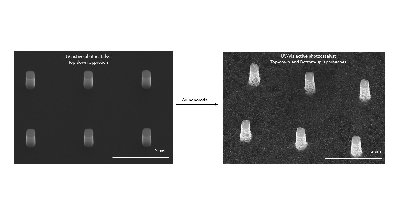
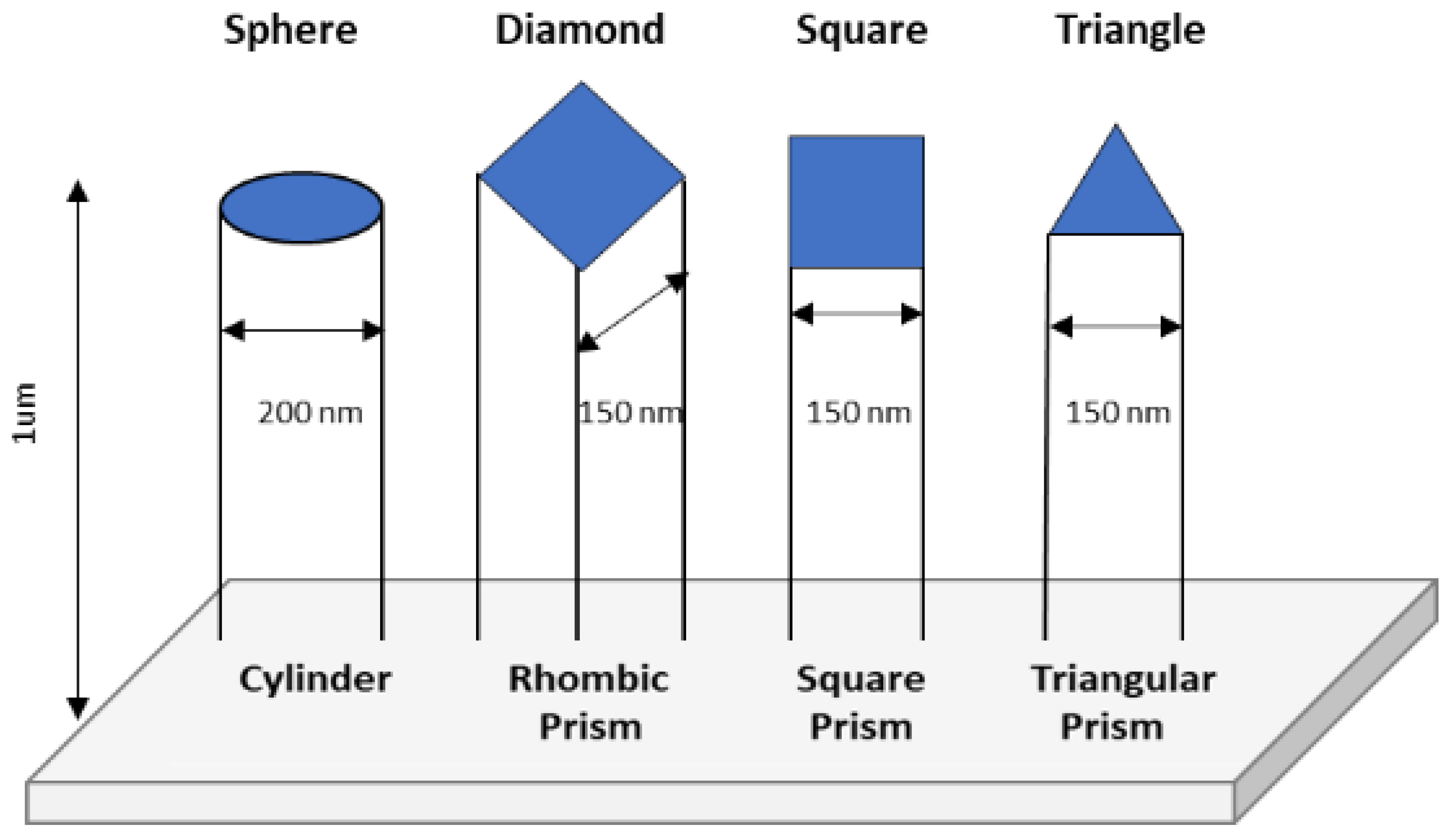
2.1. Designing UV Active Nanophotocatalysts—A Top-Down Approach

Titania is one the most appropriate candidates for photocatalytic processes in the UV region of the spectrum due to its powerful oxidation capability, superior charge transport, and corrosion resistance [8,13,18]. Its photocatalytic response can be tailored by appropriate selection of the particle’s size and shape, crystallinity, nanostructuring (surface area and adsorbent–adsorbate interaction, electron–hole recombination rate), heterojunction and synergistic effects between materials. Titania exists in three different crystal phases, including anatase, rutile and brookite. These phases have a high refractive index (anatase = 2.488, rutile = 2.609, brookite = 2.583), low absorption and low dispersion in Vis and near-infrared spectral regions, and high chemical and thermal stabilities [26]. Depending of the TiO2 crystal phase, different photocatalytic activities could be achieved.
It was previously reported that the most suitable phases of TiO2 for catalytic purposes is the anatase phase. For example, anatase TiO2 has the lowest packing density (3.8–3.9 gcm−3) and usually shows greatly superior photoactivity when compared to rutile (4.2–4.3 gcm−3) and brookite (4.1–4.2 gcm−3) TiO2 [27]. Anatase is more robust than the highly crystalline rutile phase [28,29], but it is less thermodynamically stable than the rutile phase. Other studies have shown that a mixture of different crystalline phases could provide even better photocatalytic performance. For example, the mixture of anatase and rutile TiO2 at an appropriate ratio can outperform both pure anatase or pure rutile [30,31].
A nanoparticle’s morphology has a profound effect on its properties. For example, depending on the nanomaterial’s shape and size, different optical and electronic properties can be obtained. Moreover, due to the high surface-to-volume ratio, small surface changes, such as the binding or altering of binding events, can also lead to a significant change in their physico-chemical properties [8]. For example, TiO2 nanobelts and nanospheres with identical phase structure, similar specific surface area, and similar photoadsorption efficiency show different photocatalytic activity with nanobelts, exhibiting better responses than the nanospheres. This is due to the lower electron−hole recombination rate of the nanobelts than the nanospheres and the fact that the (101) facet of the nanobelts yields an enhanced reactivity with molecular O2, facilitating the generation of superoxide radical [32]. The photocatalytic activity of TiO2 nanomaterials could be also altered by the material’s surface structure, namely surface atomic arrangement and coordination. Rutile (100) and (110) facets exhibit lower photoreduction rates toward conversion of Ag+ to metallic Ag than the (101), (111), and (001) facets [33]. The geometry of a nanoparticle is also an important factor in its catalytic performance since atoms located on edges or corners of a crystal have more uncoordinated sites typically making them more reactive [13,19,34].
Based on these findings and others, we designed shape-selective nano-photocatalysts and investigated their photocatalytic responses toward a model analyte. E-beam lithography and atomic layer deposition were utilized here to fabricate highly ordered mesoscale 2D/3D arrays of different shape TiO2 and SiO2/TiO2 nanoarchitectures. Electron beam lithography was selected for this approach, as it is one of the most powerful methods for nanostructure pattern forming and has shown the ability to create uniform ordered arrays of vertical nanostructures from numerous materials. It uses high voltage electrons (1–100 kV) to transfer nanopatterns into polymer or dielectric materials, e.g., resist (PMMA), on the substrate by directly writing [9,18]. This technique was used to create anisotropic large-scale 2D/3D silicon (Si) post arrays patterns (templates), with dimensions of 3 mm x 3 mm, from bulk silicon wafers. Subsequently, atomic layer deposition (ALD) was used to coat the post arrays in either TiO2 or core-shell SiO2-TiO2 nanomaterials. Two different composition pillars were produced, including SiO2-TiO2 and TiO2, as previous studies showed that TiO2 supported on SiO2 possess a different structure than bulk TiO2, which results in an increased photocatalytic performance [35]. Moreover, the SiO2-TiO2 surface is known to have higher mechanical strength and thermal stability than pure TiO2 [36,37].
We produced a series of four different shape longitudinal structures on silicon wafers, including cylinder, rhombic prism, square prism, and triangular prism to investigate their geometric shape dependence. The geometric shape of the tip of the pillars were as follows: sphere, diamond, square, and triangle, respectively. Figure 1 shows the dimensions of the shapes used for the E-beam patterning. These techniques allow for a great deal of size and shape control of our nanoparticles. The high conformity of ALD technique leads to evenly coated Si posts will well-defined edges and spacings. Figure 2 shows SEM images of differently shaped TiO2 or SiO2-TiO2 pillar arrays. The dimensions of the TiO2 or SiO2-TiO2 arrays after ALD process range from 200 to 300 nm wide and approximatively 1 µm long with pitch dimensions of 2 µm. The specific dimensions of each geometrical shape pillar are summarized in Table 1.
Amorphous TiO2 is produced by sol-gel, physical vapor deposition or low-temperature, atomic-layer deposition procedures [2,35,38]. The annealing of amorphous TiO2 at high temperatures in air often leads to phase transitions to its crystalline forms. It also reduces the number of defect sites, helping to improve the photocatalytic efficiency. For example, a pure anatase phase is observed between 300 and 700 °C, an anatase-rutile mixture between 700 and 900 °C, and a pure rutile phase at annealing temperatures above 900 °C [39]. In light of these studies, post-deposition annealing of the TiO2- and SiO2-TiO2-coated pillar arrays was performed at 500 °C for 2 h prior to any photocatalytic testing or surface functionalization. The presence of anatase phase TiO2 after annealing was confirmed by XRD analysis and compared to an as-deposited sample and a blank Si wafer. A peak around 26 degrees corresponding to a signature peak of anatase TiO2 is shown in Figure 3a. The TiO2-coated post arrays showed slight degradation in structure near the edges and top surface of the posts (Figure 1 SI). This may be due to the thin layer of Cr beneath the TiO2 layer on top, as the sides of the posts remain unchanged. However, there was no evidence of such structural deformities in the SiO2/TiO2-coated posts after annealing, which may be a testament to the higher stability of the mixed-oxide surface, as previously mentioned [28].
High-resolution transmission electron microscopy (HRTEM) studies confirmed the formation of the crystalline anatase phase after annealing at 500 °C for 2 h (Figure 3b,c). HRTEM images reveal the single crystal internal lattice of the SiO2-TiO2 with no observable stacking faults, twins, or volume dislocations. The recorded images indicate well-defined, parallel, “perfect and infinite,” equally spaced and continuous fringes which are oblique to the direction of elongation of the pillars. Ordered arrays of single crystal arrays structure with lattice fringes with interlayer spacings of 3.208 A were produced. This is slightly shifted from the 3.520 A lattice spacing of the (101) planes reported for anatase TiO2 [40]. However, lattice contraction could occur as SiO2 serves to support TiO2 deposition [41]. Previous studies revealed that lattice expansion/contraction depends on the type, concentration, and nature of various intrinsic defects created under different growth and processing conditions [42]. Lattice contraction of nanoscale anatase titania is also dependent of the particle size [43,44].
Energy dispersive X-ray spectroscopy (EDS) analysis of both the TiO2 and SiO2-TiO2 pillar arrays qualitatively confirmed the presence of Si, Ti, and O. The TiO2 pillar arrays were found to contain 60–80 weight% Si, 15–30 weight% O, and 6–13 weight% Ti, whereas the SiO2-TiO2 arrays were found to contain 72–90 weight% Si, 9–23 weight% O, and 1–4 weight% Ti. These results are consistent with the composition of the arrays that are primarily Si (from the Si support/core and SiO2 coating). A representative EDS analysis of a single point on the top of a SiO2-TiO2-coated post is shown in Figure 4.

2.2. Designing UV-Vis Active Nanophotocatalysts–A Combination of both Bottom-up and Top-down Approaches

To design a better photocatalyst nanostructure that is responsive to both the UV and Vis region of the spectrum, one needs to engineer the bandgap of the photocatalytic materials and light absorption in the UV/Vis region and maximize the reaction channels for the conversion. This requires a reduction in the bandgap of catalysts through nanofabrication and broadening the absorbance with multiple bandgap materials through careful design. We previously reported the production of one-dimensional core-shell Au-silica/titania nanomaterials by solution chemistry active in both Vis and UV region of the spectrum [24]. The study showed a three-fold improvement in the photocatalytic decomposition rate of MO under Vis vs. UV illumination.
Building on previous successful studies, we designed and produced a library of inexpensive, active and tunable one-dimensional titania-based nanohybrid architectures catalysts with multifunctional, and tunable broadband electromagnetic response by a combination of solution chemistries and nanolithography. Specifically, multi-bandgap nanophotocatalysts with both UV and Vis light absorption response were produced by surface decorations of UV responsive mesoscale 2D/3D nanoscale pillar arrays of TiO2 and SiO2-TiO2 with one-dimensional gold nanorods. Gold nanorods are of interest as they absorb and scatter light in the visible and near IR region of the spectrum [9,45,46]. With transverse and longitudinal plasmon bands that are highly tunable to the particle size, shape, and composition, it is possible to create tailored structures with increased efficiency toward photocatalytic reactions. This high tunability along with their chemical stability and ease of functionalization, makes AuNRs an ideal candidate for coupling to TiO2 mesoscale pillar nanoarrays [19].

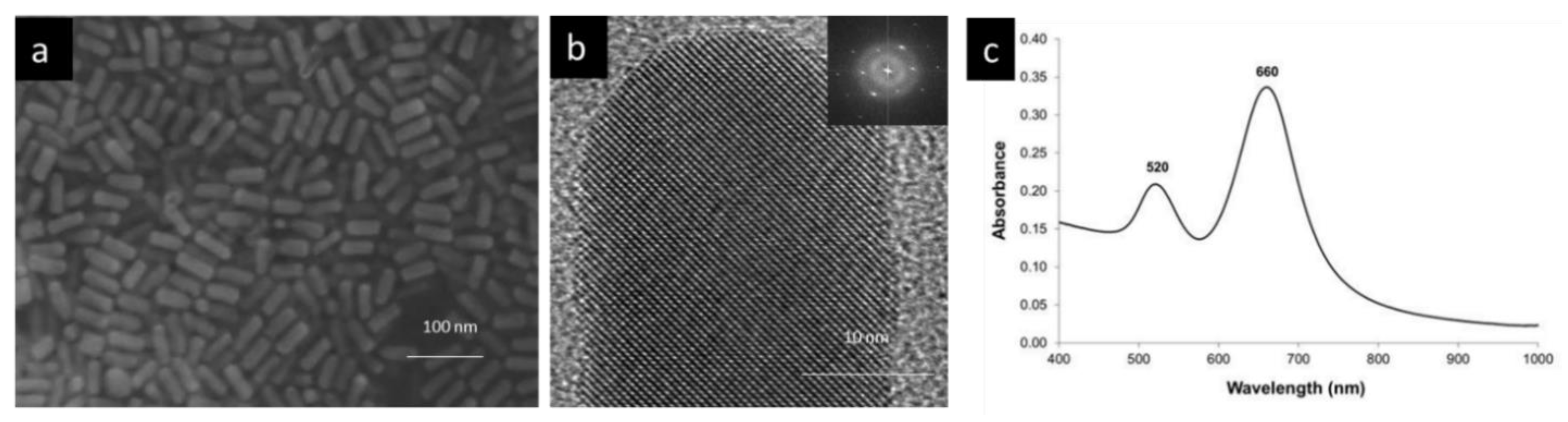
2.2.1. Preparation and Characterization of Gold Nanorods - A Bottom up Approach

The synthesis of anisotropic Au nanorods (AuNRs) was carried out via a surfactant-directed, silver-assisted wet chemical approach [7,8,9,45,46]. The stabilizing surfactant used in the synthesis of these AuNRs was cetyltrimethylammonium bromide, or CTAB, giving the particles a positive surface charge (+30mV) [8,13,18,24,45]. The AuNRs used for the subsequent surface functionalization of TiO2 and SiO2-TiO2 nanoarrays have the following dimensions: 48(± 6) nm in length and 20(± 2) nm (aspect ratio -length/width- of 2.4). Figure 5 shows an SEM image of the AuNRs, emphasizing their highly uniform size and shape (95% identical dimensions) along with the corresponding UV-Vis absorption spectrum. Gold nanorods exhibit both a transverse plasmon band around 520 nm and a longitudinal plasmon band at 660 nm. Electron diffraction and HRTEM studies recorded in the STEM mode have been used to analyze the crystallographic orientation of the gold nanorods prepared in the presence of Ag ions. In this case, the specimen, with a face centered cubic lattice, presented a high symmetry pattern of lattice points. A quick analysis allows us to observe regular spot arrays with harmonized spot spacings, and uniform angles in between the spots and planes, respectively. This demonstrates that the gold nanorods are single crystalline.

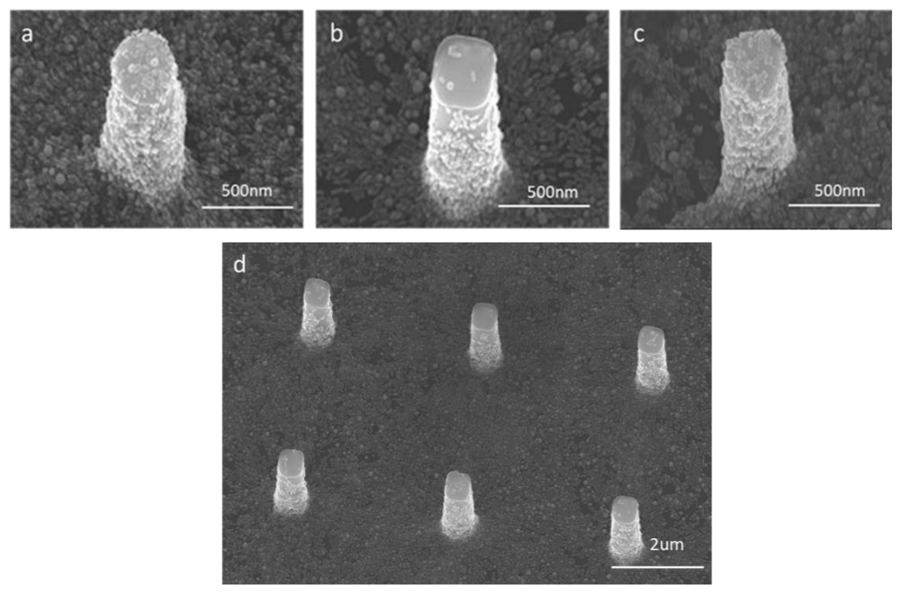
2.2.2. Self-Assembling of Au Nanorods on the Mesoscale TiO2 and SiO2-TiO2 Pillars

Over the years, many experimental and theoretical studies have been dedicated to the creation of elegant nanocomposite materials and understanding the correlations between their structure and properties [8,18]. The surface chemistry is critical in the self-assembling process and often dictates the performance, chemical stability, and reactivity of the final product. Usually, a core nanomaterial serves as a template for subsequent surface functionalization. By fine tuning the many chemical and physical interactions at the interfaces, one can produce multifunctional structures with improved functionalities and properties that are not available in the original core nanomaterial. It is well documented in the literature that Au nanoparticles form self-assembled monolayers on their surfaces when exposed to functional groups, including thiols, amine, di-sulfide, and others, due to the relative strength of the Au-S and Au-N bond [8].
In our study, a bi-functional molecular linker, in this case L-glutathione (C10H17N3O6S, structure shown in Figure 6), was used for anchoring the Au NRs to the TiO2 pillars. The carboxylate groups bind to the TiO2 surface and the thiol group binds to the Au nanoparticle. Au nanospheres (~1 nm diameter) protected by a L-glutathione layer have been previously shown to adsorb onto TiO2 thin film surfaces. The SEM images in Figure 7 clearly show that the self-assembly of AuNRs on the TiO2- and SiO2-TiO2-coated post arrays was achieved and the different shapes of the nanopillars are still distinguishable.

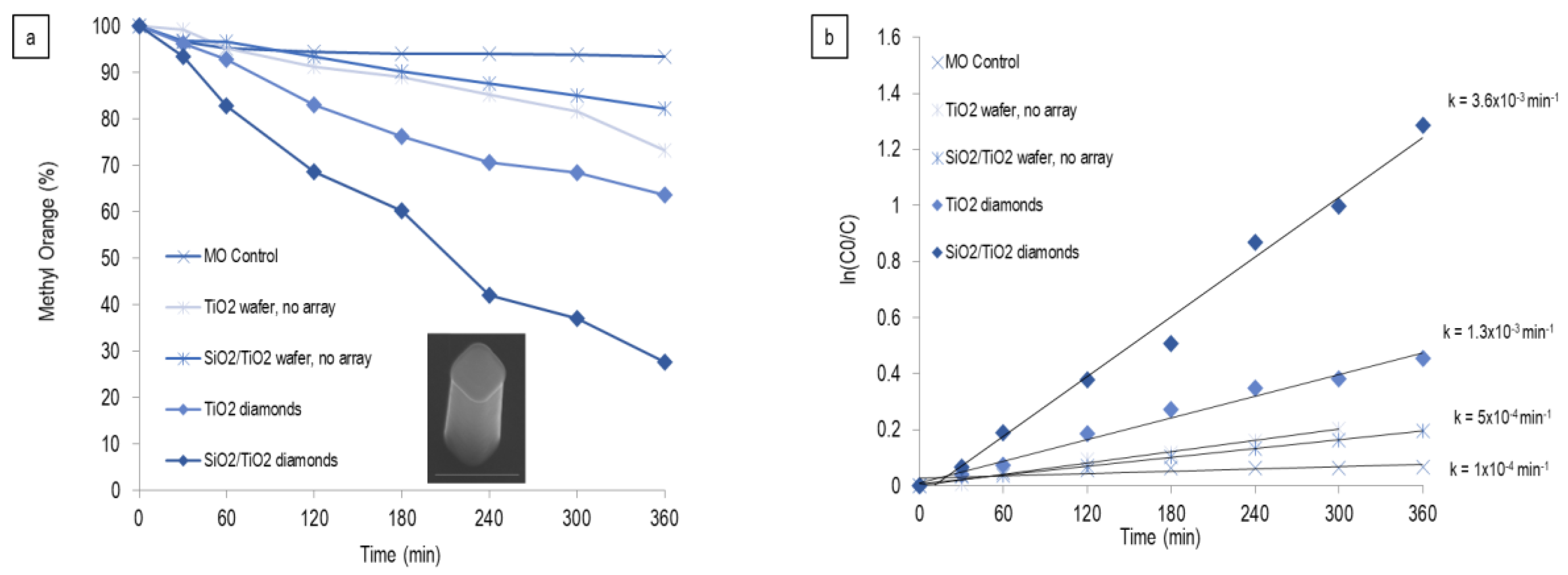
2.3. Photodegradation Studies under UV and Vis Illumination

2.3.1. Photodegradation Studies of TiO2 and SiO2-TiO2 Mesoscale Nanoarchitectures under UV Illumination

In the past few decades, numerous studies have been reported on the controlled synthesis of differently shaped metal-oxide nanoparticles, such as SiO2 and TiO2 (spheres, wires, cubes, tetragons, rods, etc.), through various sol-gel or hydrothermal methods [25,38,47,48,49]. A few of these studies have also examined the photocatalytic effects that arise from such geometrical variation. TiO2 nanowires, for example, have been shown to exhibit enhanced photocatalytic H2 evolution from aqueous methanol solutions [50]. Similarly, Wu et al. showed improved methyl orange photodegradation from TiO2 “nanobelts” compared to spherical particles [32]. However, no systematic studies on the influence of the geometry and spatial arrangement have been reported.
The photocatalytic activity of all shape mesoscale pillar arrays of TiO2 was collected and compared to the corresponding SiO2-TiO2 pillar arrays. The methyl orange (MO) was selected as the model analyte in these studies, and its photodegradation under UV illumination was explored. The arrays, which had been annealed at 500 °C for 2 h, were placed in a 10 µM solution of MO. The solutions were first equilibrated in the dark for 30–60 min and no degradation of the MO was observed (“Time 0” was measured after equilibration period). However, upon exposure to UV light, almost complete MO degradation was observed over a 6-h period. A representative single shape (in this case, diamond-shaped posts) for these experiments is shown in Figure 8.
Figure 8a shows the percentage of MO that has decomposed over time for the TiO2 and SiO2-TiO2 rhombic prism pillar arrays with a diamond tip structure. Also shown for comparison are (i) MO control solution and (ii) TiO2-coated thin film and (iii) SiO2-TiO2-coated thin film (also annealed at 500 °C) with no nanoscale array structures on the surface. The rate of photodegradation of organic pollutants can be described by the Langmuir–Hinshelwood kinetic model (Equation (1)), modified for reactions occurring at the solid–liquid interface [51,52],
R = −dC/dt = krKC/(1 + KC)
where R is the reaction rate, kr is the reaction rate constant, K is the adsorption coefficient of the reactant, and C is the reactant concentration. When C is very small, the KC product is negligible with respect to unity, resulting in apparent first-order kinetics. Of note, at irradiation time t = 0, the concentration of the reactant is the initial concentration, C = C0, giving Equation (2),
ln(C0)/C) = kt
where k is the apparent first-order rate constant. Therefore, plotting ln(C0/C) vs. t for each of the samples presented in Figure 11 gave a linear response with a slope equal to the first-order rate constant, k [4,22].
The MO control and oxide-coated Si wafers all had very small degradation rates on the order of 10−4 min−1. The rhombic prism pillars with diamond structure, however, showed an order of magnitude improvement in degradation rate with 1 × 10⁻³ and 4 × 10⁻³ min−1 for TiO2 and SiO2-TiO2 diamonds, respectively. These rates are slower than commercial Degussa P25 TiO2 films, which typically degrade MO with rates on the order of ~10−2 min−1 [22]. However, important observations (vide infra) can be made from these experiments which provide insight into the main goal of achieving Vis light activation of these materials.
Ultimately, an enhanced photocatalytic response was distinguished between core-shell SiO2-TiO2 pillar arrays and the corresponding TiO2 counterparts. The data show that core-shell SiO2-TiO2 diamond pillar arrays display four times the improvement in the photocatalytic response than the TiO2 diamond pillar arrays. All shapes show the same trend. This is not surprising, as previous studies showed that a charge imbalance resulting from combining 4-coordinated Si4+ and 6- (or 5-) coordinated Ti4+ forms new, catalytically active sites that are not present on either of the pure oxide surfaces. The isolation of tetrahedrally coordinated Ti atoms in silica correlates with an increased activity and selectivity toward photocatalytic reactions [53]. Moreover, the photocatalytic activity is highly dependent on the Ti/Si ratios [54]. The increased photocatalytic response of the TiO2/SiO2 composites when compared with TiO2 has also been attributed by others to the formation of individual nanocrystals TiO2 in SiO2, leading to an increase in surface area [55]. Another study reported that TiO2 supported on SiO2 possesses a different structure than bulk TiO2, and higher mechanical strength and thermal stability than pure TiO2, which could lead to an increased photocatalytic performance. The formation of Ti–O–Si bonds also increases the stability of anatase TiO2 [7,40,53].
Most interestingly, we found that, after repetitive photocatalytic testing of the same mesoscale nano-pillar arrays, the MO degradation significantly increases (Figure 9). By increasing the number of photocatalytic MO degradation steps, from one to three, the photocatalytic efficiency of the SiO2-TiO2 nanoscale pillar arrays doubled after each exposure. Subsequent exposures, namely fourth and fifth degradation steps, did not result in an increased photodegradation response (Figure 9a). This suggests that the maximum active sites have been reached.
The rate of reaction of MO degradation over time, upon repetitive exposure to UV light, of SiO2-TiO2-coated rhombic prism (diamond) post array increased from 20 × 10−4 to 83 × 10−4 min−1 after first or third exposure, respectively. These interesting findings could be attributed to additional surface cleaning of the photocatalyst occurring upon repetitive UV light exposure. A clean surface facilitates the adsorption of additional MO molecules on the active sites of the photocatalyst available for photocatalytic reaction. Subsequently, increasing the number of active sites available for photocatalytic reactions limits the recombination of charge carriers, electrons and holes, making the process more efficient [56]. The same trend was recorded for all shapes (data not shown). It is worth noting that, in the absence of surface nanostructuring (namely a film substrate), a significantly lower rate of reaction was recorded: 5 × 10⁻⁴ min−1.
To further understand the impact of each individual shape and crystallographic arrangement for the photocatalytic process, we tested all annealed SiO2-TiO2 nanopillar arrays of various shape structures for all photocatalytic activity. As expected, the photocatalytic activity of these mesoscale arrays was found to depend on the nanoparticle shape (Figure 10). Specifically, we found that, as expected, nanostructures with more edges and corners are more photochemically active than spherical particles, decreasing as follows: diamonds > squares > triangles > spheres.
It is well known that the rate of photocatalytic reactions is highly dependent on a multitude of factors, including size, crystallinity, number/type of defects, electron–hole recombination, and surface area, among others. The preferable adsorption of reactant and the intermediate species adsorption on the specific facets of the catalysts is critical toward the photocatalytic reaction and could be used to explain this trend. The correlation between the morphology and atomic-scale structure of nanoscale titania is well documented in the literature [57]. Petkov’s work shows that atoms in TiO2 dense-filled materials, such as nanowires, form a three-dimensional network of TiO6 octahedra, similar to that occurring in bulk TiO2 [57]. However, atoms in nanomaterials with more surface atoms exposed to the environment, such as nanotubes, are arranged in corrugated layers of TiO6 octahedra and are more efficient photocatalysts.

2.3.2. Photodegradation Studies of Au-TiO2 and Au-SiO2-TiO2 Mesoscale Nanoarchitectures under UV and Vis Illumination

In order to investigate the role of gold nanorods response to the photocatalytic degradation, the AuNR-functionalized TiO2-coated and SiO2-TiO2 post array was tested for photocatalytic activity under UV and Vis illumination (Figure 11). The absorption spectra of MO solution were monitored over 6 h and the change in the intensity of the MO absorption peak at λ = 664 nm was used to evaluate the decay rates by fitting the data to a pseudo-first-order decay equation. The MO control resulted in very small degradation rates on the order of 10−4 min−1. The TiO2-Au diamond and SiO2-TiO2 triangles, however, showed a similar degradation rate of 1 × 10⁻³ min−1, while that of the TiO2 diamond is 4 × 10⁻⁴ min−1, respectively. The bare TiO2 diamonds and SiO2-TiO2 triangles are approximately 4–5 times more active toward MO degradation in UV light than the corresponding AuNR-modified arrays under UV illumination. This is not surprising, since anchoring the Au nanorods onto the array does not cover the active TiO2 surface of the catalyst completely. This result suggests that the AuNRs are likely acting as charge recombination centers in these materials, hindering the UV light-activation of the TiO2.
The AuNR-functionalized arrays were also tested under Vis light. For these experiments, differently shaped SiO2-TiO2-coated pillar arrays with AuNRs anchored to the surface (Figure 11b) were tested and compared to a TiO2 array with no AuNRs and a MO control solution. Figure 11b shows the percentage of MO degraded over a 3-h exposure to Vis in the presence of a MO control solution, SiO2-TiO2-coated triangle post array, and SiO2-TiO2-coated sphere and triangle post arrays modified with AuNRs.
While still rudimentary, these results demonstrate that slow degradation of MO is observed for all AuNR-functionalized pillar arrays tested. The MO control solution and TiO2-coated triangle pillar array with no AuNRs showed essentially no degradation over the same exposure period. This is not surprising as it clearly indicates that the AuNRs play an essential role in sensitizing TiO2 to Vis light. Although the percentage of MO degradation for the AuNR-modified arrays is only 3%–6% over 3 h of Vis light exposure, recall that the amount of AuNRs on the surface of these arrays is limited. Once the wet chemical functionalization has been optimized and a larger percentage of the array surface is coated in AuNRs, a marked improvement in the MO degradation should result. Furthermore, this lack of Au coverage helps to explain why Au-TiO2 composite arrays are slightly more active in UV light at the present time (~10% MO degradation after 3 h, from the AuNR-TiO2 diamonds) since a large percentage of the TiO2 surface is still exposed and can be activated by UV light.
The Vis light degradation studies also demonstrate a clear shape-dependence on the photocatalytic activity of these arrays. As expected, the triangular particles are more active than their spherical counterparts, likely due to the presence of more edges and corners in the triangle array, which tends to be more reactive, as discussed in the Introduction. Interestingly, the percentage of MO degradation after just 30 min in Vis light is ~3 times higher for the triangle array versus the sphere array.

2.4. Proposed Mechanism

The absorption of photons from natural light in photocatalytic materials generates electrons and holes, which enable the reduction and oxidation of chemical species in the surrounding environment. Electrons and holes are generated when an UV-active material is illuminated by photons with energy larger than their bandgap. Typically, these processes are facilitated through adsorbed radicals, namely active oxygen species O2, HOO•, or •OH radicals, present on the TiO2 surfaces. Basically, upon UV illumination, the generated surface electrons react with the molecular oxygen (O2) producing superoxide radical anions, O2, that are subsequently protonated, creating HOO• radicals, while the holes generate •OH radicals. Ultimately, the photodegradation of MO takes place through a series of intermediate steps involving a multitude of adsorbed radical species [37,58,59]. Efficient separation of photo-generated electrons and holes, and low probability of electron–hole recombination at the redox reaction sites are the key factors determining the photocatalytic reaction efficiency. One way of improving the lifetime of electron–hole pairs is by (a) reducing the size of the material, allowing a fair mobility of the photoinduced electron–hole to be transported to the redox reaction sites at the surface before their recombination or (b) coupling the TiO2 material with a metal nanoparticle to induce a charge separation effect.
TiO2 cannot be activated by Vis light due to its large bandgap. The potential mechanisms describing the Vis light photodegradation process could be based on a combination of multiple steps and processes. Self-photosensitization of MO can occur as its absorption peak is in the VIS region of the spectrum at 664 nm [56]. Once MO is activated by Vis light, the excited electrons are shuttled in the conduction band of the TiO2 that, subsequently, produces oxidized species that drive the MO photodegradation. The hybrid TiO2-AuNRs can be also activated by Vis light. By irradiating AuNRs with Vis light and energies matching the localized surface plasmon resonance (e.g., 525 and 660 nm), “hot electrons” can be generated. These excited electrons can then be dumped in the conduction band of TiO2, leading to an enhanced photodegradation reaction [24,37,58,59]. When AuNRs are illuminated at a wavelength corresponding to their plasmon resonance, they can also serve as highly localized heat sources for the surrounding media due to nonradiative decay of surface plasmons into phonon modes. The localized heating and temperature increase generated in close proximity of the AuNRs may contribute to the enhanced photocatalytic activity [4,8,37,46,60].
Successfully understanding the underlying mechanisms driving these photo-catalytic reactions could lead to the ability to “tune” the nanomaterial composite for a wide array of different reactions. Work is in progress to gain further insights into mechanistic aspects, spatial distancing and modulation between length and space distance of nanopillars and nanorods, as well as the study of photocatalytic activities of these materials.

3. Materials and Methods

3.1. Nanoarray Fabrication

Substrate. P-type, boron-doped silicon wafers (4-inch diameter, resistivity of 1–5 Ω) were spin-coated (6000 rpm for 45 sec) with the positive E-beam resist, ZEP-520A, and baked for 2 min. Pattern. Five rows of five different shapes (~200 nm spheres, diamonds, squares, and triangles) were written onto the wafers by E-beam lithography in 3 × 3 mm arrays at a 2 µm pitch with each array separated by 10-12 mm. The wafers were exposed to the E-beam at a dose of 550 uC/cm2. Development. Exposed wafers were developed in xylenes for 30 sec then rinsed with isopropyl alcohol (IPA) and dried with N2. Developed wafers were then subjected to a 6-sec “descum” process to remove any remaining resist or residue from the exposed Si surface.
Mask. Thin film deposition (15 nm) of a Cr mask was performed in a high-vacuum, E-beam thermal evaporation chamber. Wafers were mounted on a copper block with Krytox oil. Deposition was performed at ~5 × 10⁻⁶ Torr and a deposition rate of ~1Å/sec was achieved with an E-beam current ranging around 0.1 Amps.
Lift-off. Masked wafers were sonicated in acetone for 2 min plus an additional 30 sec in fresh acetone followed by submersion in IPA to remove all metal mask and resist not bound to the exposed Si nanofeatures. The wafers were then rinsed with deionized (DI) water and dried with N2.
Si Etch. Masked wafers were etched in a reactive ion etching chamber at 20 °C, 1200 W ICP, and 30 W RF. The etching was performed at a pressure of 15 mT and a reactive plasma composition of Ar = 2 sccm, SF6 = 25 sccm, and C4F8 = 60 sccm with 5Torr He backing. Etching times of 6–7 min resulted in ~1 µm posts.

3.2. Preparation of Gold Nanorods (AuNRs)

Gold nanorods were prepared by a silver-mediated surfactant approach, as described in our previous reports [9,10]. In this method, gold seeds (1.5–2 nm) were initially synthesized for further anisotropic metal overgrowth. A solution of 2.5 × 10⁻⁴ M HAuCl4 was initially prepared in 0.1 M CTAB and 600 µL of NaBH4 (10 mM) were subsequently added at 0 °C while vigorously stirring for 2 min. The resulting gold seeds were immersed in a growth solution containing more metal salt, a structure-directing agent, and a weak reducing agent in a separate flask for the production of gold nanorods. In this step, the following aqueous solutions were added to a conical flask: 9.5 mL of 0.1 M CTAB solution, 100 µL 5 mM silver nitrate, and 0.5 mL of 10 mM chloroauric acid. Subsequently, 55 µL of 0.1 M ascorbic acid was then added followed by 12 µL gold seeds. The resulting gold nanorods were left undisturbed for 4–6 h until further use.

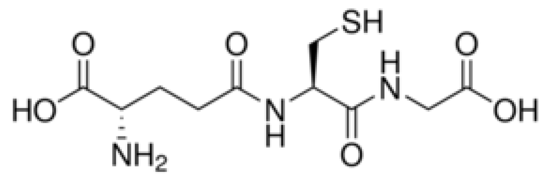
3.3. Functionalization and Characterization

3.3.1. SiO2-TiO2-Coated Cr Arrays

Atomic layer deposition (ALD) was used to coat post-etch Cr arrays with SiO2 and/or TiO2 (25–50 nm). Growth rates of ~1.17 Å/cycle for SiO2 (at 150 °C) and ~0.43 Å/cycle for TiO2 (at 200 °C) were used to calculate the number of cycles needed for a desired film thickness. Coated pillar arrays were later annealed at 500 °C for 2 h to achieve a crystalline TiO2 surface (anatase phase), which was characterized by SEM (Hitachi FESEM SU6600 and S4800), EDX, and XRD analysis.

3.3.2. AuNR-Functionalized Post Arrays

TiO2- and SiO2-TiO2-coated pillar arrays annealed at 500 °C were submerged overnight in 10 mM L-glutathione (a tripeptide, γ-L-glutamyl-L-cysteinylglycine) in EtOH. The arrays were rinsed and then placed in a solution of AuNRs (concentrated and re-dispersed in H2O) for at least 4 h. Functionalized arrays are characterized by SEM (Hitachi S4800) analysis.

3.4. Photodegradation of Methyl Orange

Nanoarray pillars (TiO2, SiO2/TiO2, AuNR-functionalized arrays, and blank controls) were tested for photodegradation of methyl orange (MO). The array (on Si wafer) was placed in a 1 cm cuvette with 1mL of 10 µM aqueous MO. The solution was equilibrated in the dark for 30–60 min before exposure to a light source. The samples were then exposed to visible (fiber optic) or UV light (365 nm LED) over a 6–8 h period. A UV-Vis light measurement of the MO solution (with catalyst removed) was obtained every hour during exposure. Laboratory lights remained off during the UV irradiation for the duration of the experiment. Experiments were conducted in Aiken, SC, USA.

4. Conclusions

We have successfully fabricated novel TiO2, SiO2-TiO2, TiO2-Au and SiO2-TiO2-Au mesoscale composite nanomaterials for photocatalytic applications. Electron-beam lithography and atomic layer deposition allowed for tremendous size and shape control of the metal oxide nanoparticles. There are several major findings from these results on UV-active nano-photocatalysts. First, it is important to note that the TiO2 and SiO2/TiO2 thin film wafers with no nanoarray show no noteworthy MO degradation when compared to the nanoscale pillar arrays. This indicates that the nanostructuring and ordered spatial arrangement of the TiO2 surface is an extremely important factor in its catalytic activity. This is likely due to the higher surface area and presence of more “active” sites on the ordered arrays of nanoparticles. The data also show that SiO2-TiO2-coated post arrays of the same shape exhibit faster degradation kinetics than the TiO2-coated arrays (~72% and 35% MO degradation over 6 h, respectively). This is not surprising since the TiO2-coated arrays have some degree of structural defects after annealing. The TiO2 layer may adhere better to SiO2 rather than Si due to the higher porosity of the SiO2 surface. Individual nanocrystalline TiO2 island may also form on the SiO2, leading to additional enhanced active sites for reactions. Also, the mixed oxide SiO2-TiO2 surface has been shown to exhibit higher stability and enhanced photocatalytic performance in other systems. The impact of defects on the structural, optical, and electronic properties are also critical factors for defining the catalytic activity of a material. The diffusion capability of carriers, electrons, and holes is affected by its crystallographic arrangement and could rationalize the increased photocatalytic activity of these nanostructures.
The photocatalytic activity of these arrays was also found to depend on the nanoparticle shape, in which particles with more edges and corners were found to be more reactive than spherical particles (i.e., the photocatalytic activity decreased as follows diamonds > squares > triangles > spheres). The potential selective preferable adsorption of reactant and the intermediate species adsorption on the specific facets of the catalysts could explain this trend.
An indirect self-assembly approach was also successfully employed to couple anisotropic Au nanorods to the TiO2 and SiO2-TiO2 pillar arrays. The combination of nanostructuring (controlling the size, shape, and spatial arrangement of particles) and coupling to Au nanorods has led to promising results for the photocatalytic applications of Vis light sensitization of TiO2. As expected, the AuNR-modified nanoarrays showed poor photocatalytic activity in UV light as the AuNRs diminish the number of UV-active sites on the TiO2 surface. However, where the bare TiO2 and SiO2-TiO2 arrays are essentially inactive in Vis light, the AuNR-functionalized arrays did show promising photocatalytic activity toward MO in Vis light (~5%–7% degradation over 3–4 h). While these results are still nascent, the AuNRs play an important role in sensitizing these TiO2 nanocatalysts to Vis light. As the methods to create these mesoscale TiO2 and TiO2-SiO2 nanostructures are highly versatile, they are amenable to scaling up.
More studies are still necessary for complete understanding and optimization of the hybrid TiO2-SiO2-AuNRs mesoscale nanoarchitectures. However, the unique size, shape, and geometry of the hybrid architectures can be further refined and exploited for future applications.

Supplementary Materials

Supplementary File 1

Author Contributions

Conceptualization and experimental design, funding acquisition and managing, formal analysis, investigation, reporting and writing, program management, supervision, S.E.H.M.; partial investigation K.H. All authors have read and agreed to the published version of the manuscript.

Funding

This work was supported by the Laboratory Directed Research and Development (LDRD) program within the Savannah River National Laboratory (SRNL). Work was conducted at SRNL under the U.S. Department of Energy Contract DE-AC09-96SR18500.

Conflicts of Interest

The authors declare no conflicts of interest.

References

  1. Isaacoff, B.P.; Brown, K.A. Progress in top-down control of bottom-up assembly. Nano Lett. 2017, 17, 6508–6510. [Google Scholar] [CrossRef] [PubMed]
  2. Biswas, A.; Bayer, I.S.; Biris, A.S.; Wang, T.; Dervishi, E.; Faupel, F. Advances in top–down and bottom–up surface nanofabrication: Techniques, applications & future prospects. Adv. Colloid Interface Sci. 2012, 170, 2–27. [Google Scholar] [PubMed]
  3. Tao, C.G.; Cullen, W.G.; Williams, E.D.; Hunyadi, S.E.; Murphy, C.J. Surface morphology and step fluctuations on silver nanowires. Surf. Sci. 2007, 601, 4939–4943. [Google Scholar] [CrossRef]
  4. Hunyadi Murph, S.E.; Larsen, G.; Lascola, R. Multifunctional hybrid Fe2O3-Au nanoparticles for efficient plasmonic heating. J. Vis. Exp. (JOVE) 2016, 108, e53598. [Google Scholar]
  5. Hunyadi Murph, S.E.; Jacobs, S.; Siegfried, M.; Hu, T.; Serkiz, S.; Hudson, J. Manganese-doped gold nanoparticles as positive contrast agents for Magnetic Resonance Imaging (MRI). J. Nanopart. Res. 2012, 14, 658–659. [Google Scholar] [CrossRef]
  6. Hunyadi Murph, S.E.; Lawrence, K.; Sessions, H.; Brown, M.; Larsen, G. Controlled Release of Hydrogen from Hydride-Magnetic Nanomaterials. ACS Appl. Mater. Interfaces 2020, 12, 9478–9488. [Google Scholar] [CrossRef]
  7. Hunyadi Murph, S.E.; Coopersmith, K. Fabrication of silver-rhodium nanomaterials for chemical sensing applications. In Nanocomposites VI: Nanoscience and Nanotechnology in Advanced Composites; The Minerals, Metals & Materials Series; Srivatsan, T., Gupta, M., Eds.; Springer: Berlin/Heidelberg, Germany, 2020; pp. 95–104. [Google Scholar]
  8. Hunyadi Murph, S.E. Anisotropic metallic and metallic oxide nanostructures-Correlation between their shape and properties. In Anisotropic and Shape-Selective Nanomaterials: Structure-Property Relationships; Nanostructure Science and Technology series; Springer Publisher: Berlin/Heidelberg, Germany, 2017; pp. 105–151. [Google Scholar]
  9. Hunyadi Murph, S.E.; Larsen, G.; Coopersmith, K. Anisotropic and Shape-Selective Nanomaterials: Structure-Property Relationships; Nanostructure Science and Technology series; Springer Publisher: Berlin/Heidelberg, Germany, 2017; pp. 1–470. [Google Scholar]
  10. Mahmoud, M.A. Tunable plasmonic neutral density filters and chromatic polarizers: Highly packed 2D arrays of plasmonic nanoparticle on elastomer substrate. J. Phys. Chem. C 2016, 120, 18249–18258. [Google Scholar] [CrossRef]
  11. Pang, J.; Xiong, S.; Jaeckel, F.; Sun, Z.; Dunphy, D.; Brinker, C.J. Free-standing, patternable nanoparticle polymer monolayer arrays formed by evaporation induced self-assembly at a fluid interface. J. Am. Chem. Soc. 2008, 130, 3284–3285. [Google Scholar] [CrossRef]
  12. Johnston-Peck, A.C.; Wang, J.; Tracy, J.B. Formation and grain analysis of spin-cast magnetic nanoparticle monolayers. Langmuir 2011, 27, 5040–5046. [Google Scholar] [CrossRef]
  13. Hunyadi Murph, S.E.; Serkiz, S.; Fox, E.; Colon-Mercado, H.; Sexton, L.; Siegfried, M. Synthesis, functionalization, characterization and application of controlled shape nanoparticles in energy production, Fluorine-Related Nanoscience with Energy Applications. ACS Symp. Ser. 2011, 1064, 127–163. [Google Scholar]
  14. Namdari, N.; Mohammadian, B.; Jafari, P.; Sojoudi, H.; Ghasemi, H.; Rizvi, R. Advanced functional surfaces through controlled damage and instabilities. Mater. Horiz. 2020, 7, 366–396. [Google Scholar] [CrossRef]
  15. Nebel, R.; Minhová Macounová, K.; Tarábková, H.; Kavan, L.; Krtil, P.J. Selectivity of Photoelectrochemical Water Splitting on TiO2 Anatase Single Crystals. Phys. Chem. C 2019, 123, 10857–10867. [Google Scholar]
  16. Kun, Y.; Basnet, P.; Sessions, H.; Larsen, G.; Hunyadi Murph, S.E.; Zhao, Y. Fe2O3/TiO2 Core-Shell Nanorod Array for Visible Light Photocatalysis. Catal. Today Spec. Issue C1 Catal. Chem. 2016, 270, 51–58. [Google Scholar]
  17. Hunyadi Murph, S.E.; Larsen, G.K.; Korinko, P.; Coopersmith, K.J.; Summer, A.J.; Lewis, R. Nanoparticle Treated Stainless Steel Filters for Metal Vapor Sequestration. JOM 2017, 69, 162–172. [Google Scholar] [CrossRef]
  18. Hunyadi Murph, S.E.; Heroux, K.; Turick, C.; Thomas, D. Metallic and Hybrid Nanostructures: Fundamentals and Applications. In Applications of Nanomaterials 2012, Series ISBN: 1-62699-000-X, Nanomaterials and Nanostructures, Volume (4); Govil, J.N., Ed.; Studium Press LLC: Houston, TX, USA, 2012; ISBN 1-62699-004-2. [Google Scholar]
  19. Sułek, A.; Pucelik, B.; Kuncewicz, J.; Dubin, G.; Janusz, M. Dąbrowski Sensitization of TiO2 by halogenated porphyrin derivatives for visible light biomedical and environmental photocatalysis. Catal. Today 2019, 335, 538–549. [Google Scholar] [CrossRef]
  20. Tian, C.; Li, W.; Pan, K.; Zhang, Q.; Tian, G.; Zhou, W.; Fu, H. One pot synthesis of Ag nanoparticle modified ZnO microspheres in ethylene glycol medium and their enhanced photocatalytic performance. J. Solid State Chem. 2010, 183, 2720–2725. [Google Scholar] [CrossRef]
  21. Ramesha, G.K.; Brennecke, J.F.; Kamat, P.V. Origin of Catalytic Effect in the Reduction of CO2 at Nanostructured TiO2 Films. ACS Catal. 2014, 4, 3249–3254. [Google Scholar] [CrossRef]
  22. Ji, S.M.; Jun, H.; Jang, J.S.; Son, H.C.; Borse, P.H.; Lee, J.S. Photocatalytic hydrogen production from natural seawater. J. Photochem. Photobiol. A Chem. 2007, 189, 141–144. [Google Scholar] [CrossRef]
  23. Justicia, I.; Garcia, G.; Battiston, G.A.; Gerbasi, R.; Ager, F.; Guerra, M.; Caixach, J.; Pardo, J.A.; Riverad, J.; Figueras, A. Photocatalysis in the visible range of sub-stoichiometric anatase films prepared by MOCVD. Electrochim. Acta 2005, 50, 4605–4608. [Google Scholar] [CrossRef]
  24. Hunyadi Murph, S.E. One-Dimensional Plasmonic Nano-photocatalysts: Synthesis, Characterization and Photocatalytic Activity Solar Hydrogen and Nanotechnology VI, edited by Yasuhiro Tachibana. Proc. SPIE 2011, 8109, 1–11. [Google Scholar]
  25. Li, D.; Seaman, J.; Hunyadi Murph, S.E.; Kaplan, D.; Taylor-Pashow, T.; Feng, R.; Chang, H.; Tandukar, M. Porous iron material for TcO4- and ReO4- sequestration from groundwater under ambient oxic conditions. J. Hazard. Mater. 2019, 374, 177–185. [Google Scholar] [CrossRef] [PubMed]
  26. Zallen, R.; Moret, M.P. The optical absorption edge of brookite TiO2. Solid State Commun. 2006, 137, 154–157. [Google Scholar] [CrossRef]
  27. Liu, G.; Wang, L.; Yang, H.G.; Cheng, H.M.; Lu, G.Q. Titania-based photocatalysts - crystal growth, doping and heterostructuring. J. Mater. Chem. 2010, 20, 831–843. [Google Scholar] [CrossRef]
  28. Jogi, I.; Pars, M.; Aarik, J.; Aidla, A.; Laan, M.; Sundqvist, J.; Oberbeck, L.; Heitmann, J.; Kukli, K. Conformity and structure of titanium oxide films grown by atomic layer deposition on silicon substrates. Thin Solid Films 2008, 516, 4855–4862. [Google Scholar] [CrossRef]
  29. Matthews, A. The crystallization of anatase and rutile from amorphous titanium dioxide under hydrothermal conditions. Am. Mineral. 1976, 61, 419–424. [Google Scholar]
  30. Schneider, J.; Matsuoka, M.; Takeuchi, M.; Zhang, J.; Horiuchi, Y.; Anpo, M. Understanding TiO2 photocatalysis: Mechanisms and materials. Chem. Rev. 2014, 114, 9919–9986. [Google Scholar] [CrossRef]
  31. Hurum, D.C.; Agrios, A.G.; Crist, S.E.; Gray, K.A.; Rajh, T.; Thurauer, M.C. Probing reaction mechanisms in mixed phase TiO2 by EPR. J. Electron. Spectrosc. 2006, 150, 155–163. [Google Scholar] [CrossRef]
  32. Wu, N.; Wang, J.; Tafen, D.N.; Wang, H.; Zheng, J.-G.; Lewis, J.P.; Liu, X.; Leonard, S.S.; Manivannan, A. Shape-Enhanced Photocatalytic Activity of Single-Crystalline Anatase TiO2 (101) Nanobelts. J. Am. Chem. Soc. 2010, 132, 6679–6685. [Google Scholar] [CrossRef] [Green Version]
  33. Hotsenpiller, P.A.M.; Bolt, J.D.; Farneth, W.E.; Lowekamp, J.B.; Rohrer, G.S. Orientation Dependence of Photochemical Reactions on TiO2 Surfaces. J. Phys. Chem. B 1998, 102, 3216–3226. [Google Scholar] [CrossRef]
  34. Paramasivam, I.; Macak, J.M.; Schmuki, P. Photocatalytic activity of TiO2 nanotube layers loaded with Ag and Au nanoparticles. Electrochem. Commun. 2008, 10, 71–75. [Google Scholar] [CrossRef]
  35. Fauzi, A.A.; Jalil, A.A.; Mohamed, M.; Triwahyono, S.; Jusoh, N.W.C.; Rahman, A.F.A.; Aziz, F.F.A.; Hassan, N.S.; Khusnun, N.F.; Tanaka, H. Altering fiber density of cockscomb-like fibrous silica-titania catalysts for enhanced photodegradation of ibuprofen. J. Envirom. Manag. 2018, 227, 34–43. [Google Scholar] [CrossRef] [PubMed]
  36. Sirimahachai, U.; Ndiege, N.; Chandrasekharan, R.; Wongnawa, S.; Shannon, M.A. Nanosized TiO2 particles decorated on SiO2 spheres (TiO2/SiO2): Synthesis and photocatalytic activities. J. Sol-gel Sci. Technol. 2010, 56, 53–60. [Google Scholar] [CrossRef]
  37. He, Y.; Basnet, P.; Hunyadi Murph, S.E.; Zhao, Y. Ag Nanoparticle Embedded TiO2 Composite Nanorod Arrays Fabricated by Oblique Angle Deposition: Toward Plasmonic Photocatalysis. ACS Appl. Mater. Interfaces 2013, 5, 11818–11827. [Google Scholar] [CrossRef] [PubMed]
  38. Hunyadi Murph, S.E.; Murphy, C.J. Patchy Silica-Coated Silver Nanowires as SERS Substrates. J. Nanopart. Res. 2013, 15, 1607. [Google Scholar] [CrossRef] [Green Version]
  39. Martin, N.; Rousselot, V.; Rondot, D.; Palmino, F.; Mercier, R. Microstructure modification of amorphous titanium oxide thin films during annealing treatment. Thin Solid Films 1997, 300, 113–121. [Google Scholar] [CrossRef]
  40. Dai, S.; Wu, S.; Sakai, T.; Du, Z.; Sakai, H.; Abe, M. Preparation of Highly Crystalline TiO2 Nanostructures by Acid-assisted Hydrothermal Treatment of Hexagonal structured Nanocrystalline Titania/Cetyltrimethyammonium Bromide Nanoskeleton. Nanoscale Res. Lett. 2010, 5, 1829–1835. [Google Scholar] [CrossRef] [Green Version]
  41. Russell, J.L.; Mallouk, T.E. Double Replication of Silica Colloidal Crystal Films. ACS Appl. Mater. Interfaces 2017, 9, 42075–42083. [Google Scholar] [CrossRef]
  42. Santara, B.; Giri1, P.K.; Imakita, K.; Fujii, M. Microscopic origin of lattice contraction and expansion in undoped rutile TiO2 nanostructures. J. Phys. D Appl. Phys. 2014, 47, 215302. [Google Scholar] [CrossRef] [Green Version]
  43. Zhang, H.; Chena, B.; Banfield, J.B. The size dependence of the surface free energy of titania nanocrystals Phys. Chem. Chem. Phys. 2009, 11, 2553–2558. [Google Scholar] [CrossRef]
  44. Tanemura, S.; Miao, L.; Wunderlich, W.; Tanemura, M.; Mori, Y.; Toh, S.; Kaneko, K. Fabrication and characterization of anatase/rutile–TiO2 thin films by magnetron sputtering: A review. Sci. Technol. Adv. Mater. 2005, 6, 11–17. [Google Scholar] [CrossRef] [Green Version]
  45. Hunyadi Murph, S.E.; Murphy, C.; Colon-Mercado, H.; Torres, R.; Heroux, K.; Fox, E.; Thompson, L.; Haasch, R. Tuning of size and shape of Au-Pt nanocatalyst for direct methanol fuel cells. J. Nanopart. Res. 2011, 13, 6347–6364. [Google Scholar] [CrossRef]
  46. Larsen, G.; Farr, W.; Hunyadi Murph, S.E. Multifunctional Fe2O3-Au Nanoparticles with Different Shapes: Enhanced Catalysis, Photothermal Effects, and Magnetic Recyclability. J. Phys. Chem. C 2016, 120, 15162–15172. [Google Scholar] [CrossRef]
  47. Mazinani, B.; Masrom, A.K.; Beitollahi, A.; Luque, R. Photocatalytic activity, surface area and phase modification of mesoporous SiO2–TiO2 prepared by a one-step hydrothermal procedure. Ceram. Int. 2014, 40, 11525–11532. [Google Scholar] [CrossRef]
  48. Chen, H.S.; Huang, S.H.; Perng, T.P. Preparation and Characterization of Molecularly Homogeneous Silica–Titania Film by Sol–Gel Process with Different Synthetic Strategies. ACS Appl. Mater. Interfaces 2012, 4, 5188–5195. [Google Scholar] [CrossRef] [PubMed]
  49. Hunyadi, S.E.; Murphy, C.J. Tunable One-Dimensional Silver-Silica Nanopeapod Architectures. J. Phys. Chem. B 2006, 110, 7226–7231. [Google Scholar] [CrossRef]
  50. Jitputti, J.; Suzuki, Y.; Yoshikawa, S. Synthesis of TiO2 nanowires and their photocatalytic activity for hydrogen evolution. Catal. Commun. 2008, 9, 1265–1271. [Google Scholar] [CrossRef]
  51. Al-Ekabi, H.; Serpone, N. Kinetic Studies in Heterogeneous Photocatalysis. 1. Photocatalytic Degradation of Chlorinated Phenols in Aerated Aqueous Solutions over TiO2 Supported on a Glass Matrix. J. Phys. Chem. 1998, 92, 5726. [Google Scholar] [CrossRef]
  52. Houas, A.; Lachheb, H.; Ksibi, M.; Elaloui, E.; Guillard, C. Herrmann, Photocatalytic degradation pathway of methylene blue in water. J. Appl. Catal. B Environ. 2001, 31, 145–157. [Google Scholar] [CrossRef]
  53. Davis, R.J.; Liu, Z. Titania-Silica: A Model Binary Oxide Catalyst System. Chem. Mater. 1997, 9, 2311–2324. [Google Scholar] [CrossRef]
  54. Dohshi, S.; Takeuchi, M.; Anpo, M. Effect of the local structure of Ti-oxide species on the photocatalytic reactivity and photo-induced super-hydrophilic properties of Ti/Si and Ti/B binary oxide thin films. Catal. Today 2003, 85, 199–206. [Google Scholar] [CrossRef]
  55. Nilchia, A.; Janitabar-Darzia, S.; Mahjoubb, A.R.; Rasouli-Garmarodia, S. New TiO2/SiO2 nanocomposites - Phase transformations and photocatalytic studies. Colloids Surf. A Physicochem. Eng. Asp. 2010, 361, 25–30. [Google Scholar] [CrossRef]
  56. Sang, Y.; Liu, H.; Umar, A. Photocatalysis from UV/Vis to near-infrared light: Towards full solar-light spectrum activity. Chem. Cat. Chem. 2015, 7, 559–573. [Google Scholar]
  57. Pradhan, S.K.; Mao, Y.; Wong, S.S.; Chupas, P.; Petkov, V. Atomic-Scale Structure of Nanosized Titania and Titanate: Particles, Wires, and Tubes. Chem. Mater. 2007, 19, 6180–6186. [Google Scholar] [CrossRef]
  58. Wu, T.; Liu, G.; Zhao, J.; Hidaka, H.; Serpone, N. Photoassisted degradation of dye pollutants. V. Self-photosensitized oxidative transformation of Rhodamine B under visible light irradiation in aqueous TiO2 dispersions. J. Phys. Chem. B 1998, 102, 5845–5851. [Google Scholar] [CrossRef]
  59. Chatterjee, D.; Patnam, V.R.; Sikdar, A.; Joshi, P.; Misra, R.; Rao, N.N. Kinetics of the decoloration of reactive dyes over visible light-irradiated TiO2 semiconductor photocatalyst. J. Hazard. Mater. 2008, 156, 435–441. [Google Scholar] [CrossRef] [PubMed]
  60. Hunyadi Murph, S.E.; Coopersmith, K.; Larsen, G. Nanoscale Materials: Fundamentals and Emergent Properties. In Anisotropic and Shape-Selective Nanomaterials: Structure-Property Relationships; Nanostructure Science and Technology series; Springer Publisher: Berlin/Heidelberg, Germany, 2017; pp. 7–28. [Google Scholar]
Figure 1. Different geometries used in E-beam pattern for nanoarrays.
Catalysts 10 00532 g001
Figure 2. (a) Fully fabricated nanoarrays on Si wafer; each square dimensions 3 mm × 3 mm; (b,g) SEM images of different shaped TiO2- and SiO2/TiO2-coated post arrays. Scale: (b) 50 µm, (c) 3 µm, (dg) 500 nm for all SEM images.
Catalysts 10 00532 g002
Figure 3. (a) XRD analysis of TiO2 pillar coated Si post array before and after annealing at 500 °C. The blue and green line spectra in the bottom portion of the figure are the reference spectra for anatase and rutile phase TiO2, respectively; (b,c) high-resolution transmission electron microscopy (HRTEM) analysis before annealing and after annealing at 500 °C, respectively, showing the amorphous phase (b) and crystalline phase (c).
Catalysts 10 00532 g003
Figure 4. Energy dispersive X-ray spectroscopy (EDS) analysis of SiO2-TiO2 coated diamond pillar arrays.
Catalysts 10 00532 g004
Figure 5. (a) SEM image, (b) HRTEM image—inset electron diffraction, and (c) UV-Vis spectrum of AuNRs.
Catalysts 10 00532 g005
Figure 6. Structure of L-glutathione.
Catalysts 10 00532 g006
Figure 7. SEM images of different shaped AuNR-functionalized TiO2 and SiO2-TiO2 nanopost arrays. (a) spheres, (b) squares, (c) triangles, (d) square arrays.
Catalysts 10 00532 g007
Figure 8. Photocatalytic response of TiO2 and SiO2-TiO2-coated rhombic prism (diamond) post array; (a) percentage of methyl orange degradation over time upon exposure to UV light of SiO2-TiO2-coated rhombic prism (diamond) post array, inset showing an SEM structure—scale 500 µm; (b) rate of reaction of methyl orange degradation over time upon exposure to UV light of SiO2-TiO2-coated rhombic prism (diamond) post array.
Catalysts 10 00532 g008
Figure 9. (a) Percentage of methyl orange (MO) degradation over time upon repetitive exposure to UV light of SiO2-TiO2-coated rhombic prism (diamond) post array, (b) Rate of reaction of MO degradation over time upon repetitive exposure to UV light of SiO2-TiO2-coated rhombic prism (diamond) post array.
Catalysts 10 00532 g009
Figure 10. Photocatalytic response on all shape pillar arrays showing a shape dependence with the nanostructures with more edges and tips displaying an enhanced response.
Catalysts 10 00532 g010
Figure 11. (a) Photodegradation rate of MO upon exposure to UV light and (b) percentage of methyl orange degradation over time upon Vis light.
Catalysts 10 00532 g011
Table 1. Dimensions of different shaped mesoscale TiO2- and SiO2-TiO2 coated pillar arrays.
-TiO2-CoatedSiO2-TiO2-Coated
SpheresDiameter: 329 (± 11) nmDiameter: 325 (± 3) nm
DiamondsL: 284 (± 7) nm
Diagonal: 306 (± 3) nm
L: 272 (± 6) nm
Diagonal: 325 (± 8) nm
SquaresL: 272 (± 7) nmL: 289 (± 5) nm
TrianglesL: 237 (± 5) nmL: 246 (± 5) nm

