Article

A Highly Efficient Monolayer Pt Nanoparticle Catalyst Prepared on a Glass Fiber Surface

1
Graduate School of Engineering, Kagawa University, Takamatsu, Kagawa 761-0396, Japan
2
Faculty of Engineering and Design, Kagawa University, Takamatsu, Kagawa 761-0396, Japan
3
Kurashiki Kako Co., Ltd., Kurashiki, Okayama 712-8555, Japan
4
Rika Research Institute G.K., Hamamachi, Daito Shi, Osaka 574-0041, Japan
*
Author to whom correspondence should be addressed.
Catalysts 2020, 10(5), 472; https://doi.org/10.3390/catal10050472
Submission received: 9 April 2020 / Revised: 22 April 2020 / Accepted: 23 April 2020 / Published: 25 April 2020
(This article belongs to the Special Issue Sustainable and Environmental Catalysis)

Abstract

:
Over the past few years, various nanoparticle-supported precious metal-based catalysts have been investigated to reduce the emission of harmful substances from automobiles. Generally, precious metal nanoparticle-based exhaust gas catalysts are prepared using the impregnation method. However, these catalysts suffer from the low catalytic activity of the precious metal nanoparticles involved. Therefore, in this study, we developed a novel method for preparing highly efficient glass fiber-supported Pt nanoparticle catalysts. We uniformly deposited a single layer of platinum particles on the support surface using a chemically adsorbed monomolecular film. The octane combustion performance of the resulting catalyst was compared with that of a commercial catalyst. The precious metal loading ratio of the proposed catalyst was approximately seven times that of the commercial catalyst. Approximately one-twelfth of the mass of the proposed catalyst exhibited a performance comparable to that of the commercial catalyst. Thus, the synthesis method used herein can be used to reduce the weight, size, and manufacturing cost of exhaust gas purification devices used in cars.

1. Introduction

Carbon monoxide, hydrocarbons, nitrogen oxides (NOx), and particulate matter such as soot are harmful air pollutants emitted from automobiles. Vehicle emission regulations are becoming increasingly stringent. To reduce the emission of harmful pollutants from automobiles and meet the demand for energy conservation, researchers have attempted to improve the performance of precious metal catalysts used in automobile exhaust gas purification devices and fuel cells. Conventionally, these catalysts are supported on a porous oxide such as silicon dioxide (silica: SiO2) or aluminum oxide (alumina: Al2O3) or a substrate with a large specific surface area such as activated carbon. Supported precious metal nanoparticle catalysts based on metals such as Pt, Rh, and Pd have been widely investigated [1,2,3,4]. Such precious metal nanoparticle-based catalysts are typically prepared using the impregnation method [5]. However, the precious metal nanoparticles in the catalysts prepared using this method aggregate at high temperatures, and hence show poor dispersion. Moreover, it is difficult to control the nanoparticle diameter using this method. This results in a significant reduction in the effective surface area and catalytic activity of the nanoparticles. Moreover, precious metals (particularly Pt group metals) are highly expensive, and hence should ideally be used in limited quantities. Motivated by these challenges, herein, we developed a novel method for preparing highly efficient glass fiber-supported Pt nanoparticle catalysts. We deposited Pt nanoparticles uniformly on a chemically adsorbed monomolecular film formed on the surface of a glass fiber support. The nanoparticles were densely packed in a single layer to avoid wastage. The monomolecular film could be removed by heat treatment. The objective of this study was to develop a highly efficient Pt catalyst with a large effective surface area that could maintain high stability and catalytic activity even under high temperature environments such as engine exhaust devices.

2. Results and Discussion

2.1. Observation of Pt Catalyst

Figure 1 shows the field emission scanning electron microscopy (FE-SEM) images of the Pt catalyst surface. Table 1 lists the precious metal loading rates (precious metal particle weight/catalyst weight × 100) of the Pt catalyst prepared herein and the commercial catalyst.
Figure 1a,b reveal that Pt nanoparticles (on the scale of 10 nm) were dispersed on a single layer on the surface of the glass fiber substrate. Moreover, the Pt particles exhibited minimal aggregation because of sintering at 350 °C (Figure 1b). However, the Pt particles could not be grafted when the 3-mercaptopropyltrimethoxysilane (MPTS) monolayer was formed (Figure 1c). This suggests that using a chemically adsorbed monolayer with a terminal thiol (-SH) is an effective route for forming a single layer of Pt particles with a large specific surface area. As can be observed from Table 1, the loading ratio of the Pt catalyst prepared in this study was approximately seven times larger than that of the commercially available catalyst.

2.2. Thermal Characterization during Catalyst Preparation

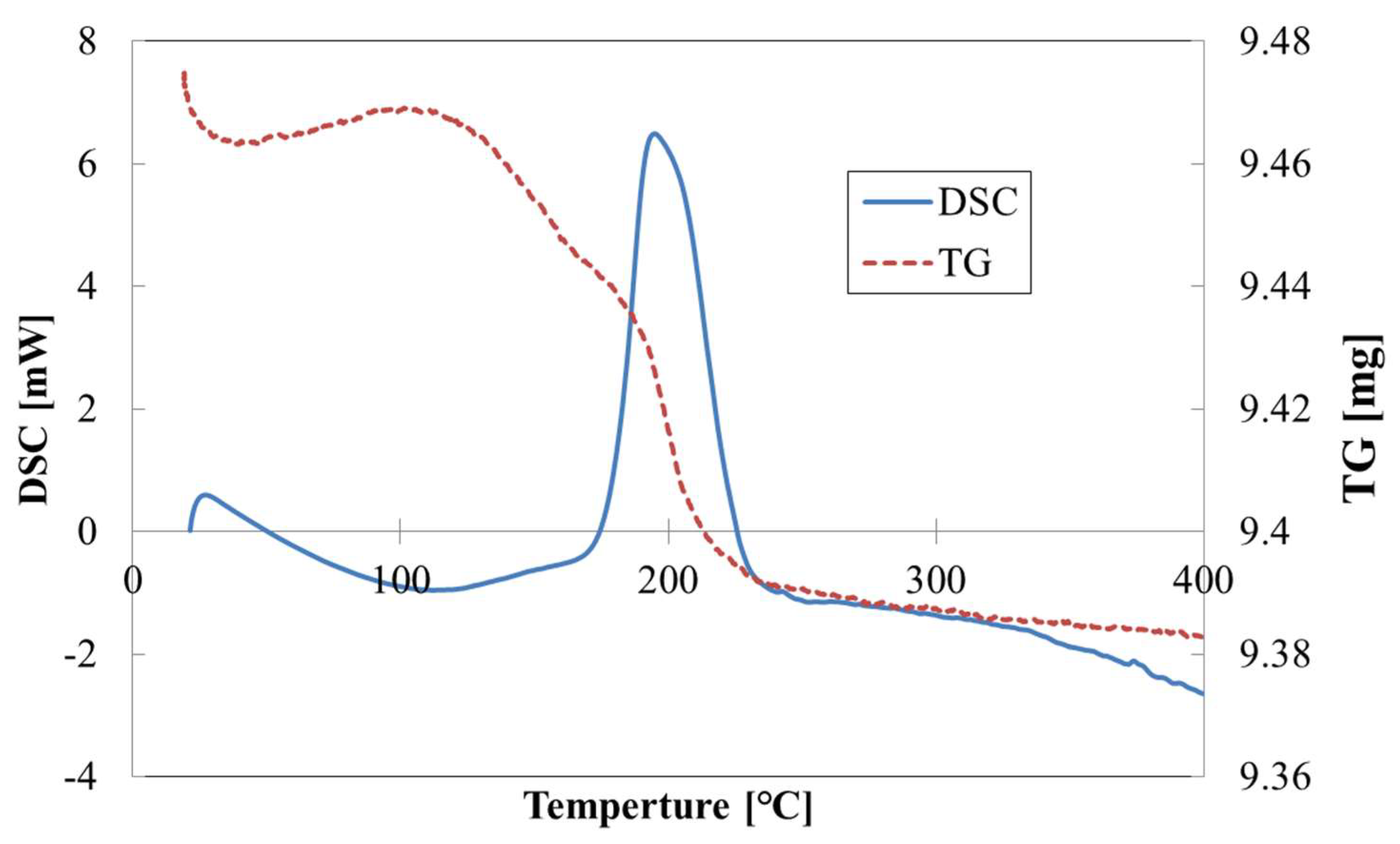
Figure 2 shows the thermogravimetry–differential scanning calorimetry (TG–DSC) results of the Pt catalyst. The catalyst showed weight loss as the temperature approached 200 °C. Hence, a DSC peak was observed. This peak can be attributed to the volatilization of MPTS, whose boiling point is approximately 215 °C. The results show that the weight of the MPTS lost by volatilization decreased and that the chemisorbed monomolecular film was sufficiently removed by heating the catalyst at 350 °C.

2.3. Effective Surface Area of the Catalyst

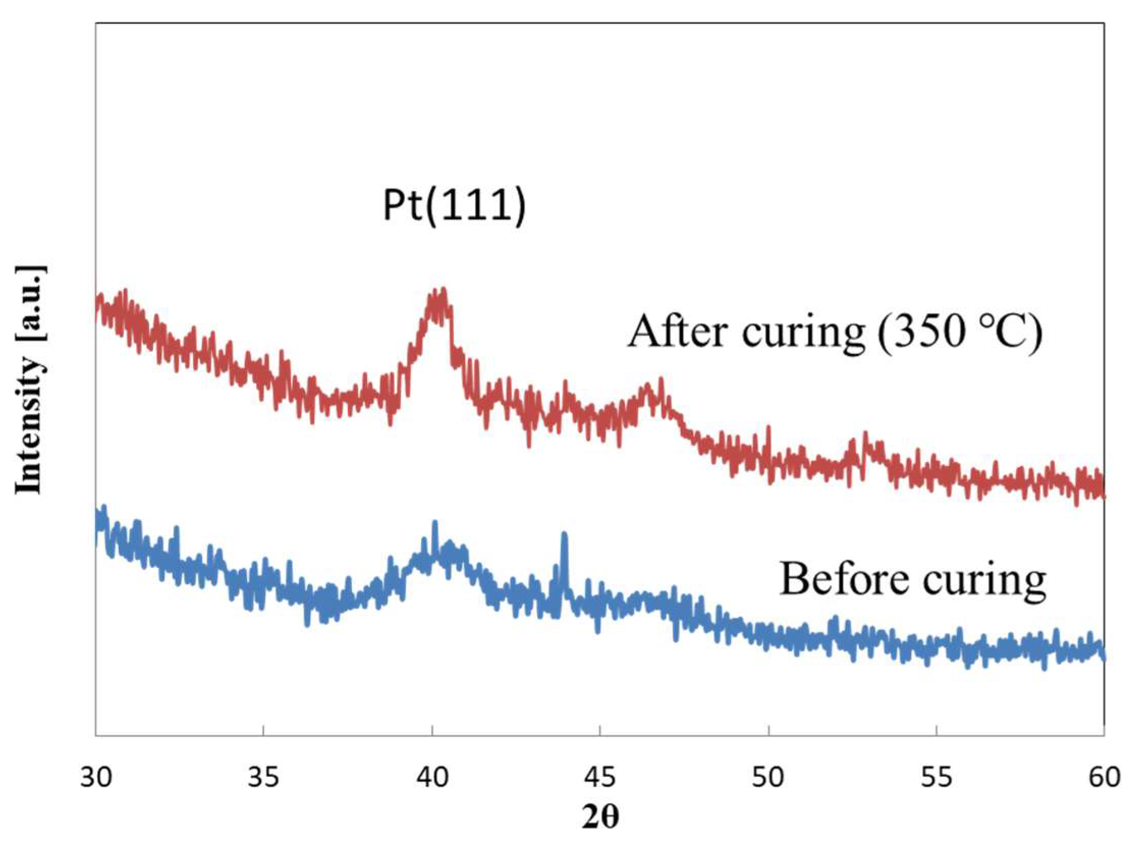
Figure 3 shows the X-ray diffraction (XRD) results of the Pt catalyst before and after the heat treatment. The catalyst showed a Pt peak at 2θ = approximately 40°. After heat treatment, the intensity of this peak increased, whereas the full width at half maximum decreased. This suggests that the particles aggregated, and the particle diameter increased after the heat treatment. This also suggests that the specific surface area of the particles decreased after the heat treatment. However, as the peak obtained after the heat treatment was not extremely sharp, it can be stated that the specific surface area required for the catalytic reaction was sufficient.
It was assumed that the particles shown in Figure 1 a were approximately 5 nm in diameter. In addition, the surface area and volume per particle were approximately 3.14 × 10⁻¹⁶ m2 and 5.24 × 10⁻¹⁹ cm3, respectively. Since the density of platinum was 21.45 g/cm3, the weight and number of units per particle were 1.12 × 10⁻¹⁷ g and 8.90 × 10¹⁶, respectively. Moreover, the BET surface area was approximately 27.96 m2/g. In contrast, Figure 3 shows that the BET surface area decreased to approximately 14.02 m2/g because the half width before and after heating had nearly doubled in size. Furthermore, as described above, since the catalytic effect was considered to be saturated at 300 °C or higher, it was found that a sufficient catalytic effect was exhibited by the BET surface area of the platinum particles after the heat treatment. In the referenced literature, the average particle size of platinum was 62 nm. The BET surface area calculated from this was approximately 4.37 mm2/g. From this, it is considered that the platinum catalyst developed in this study has a large BET surface area and exhibits high performance [6].

2.4. Catalyst Performance Evaluation

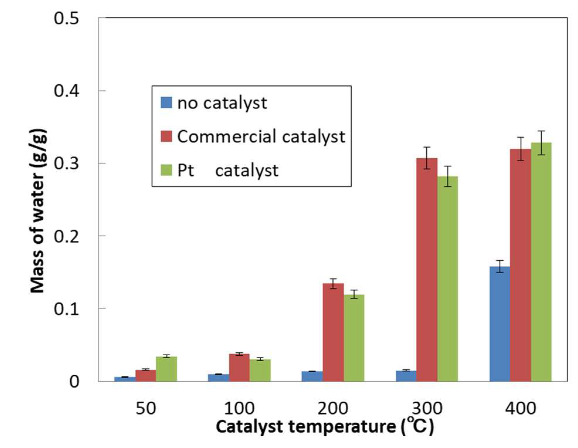
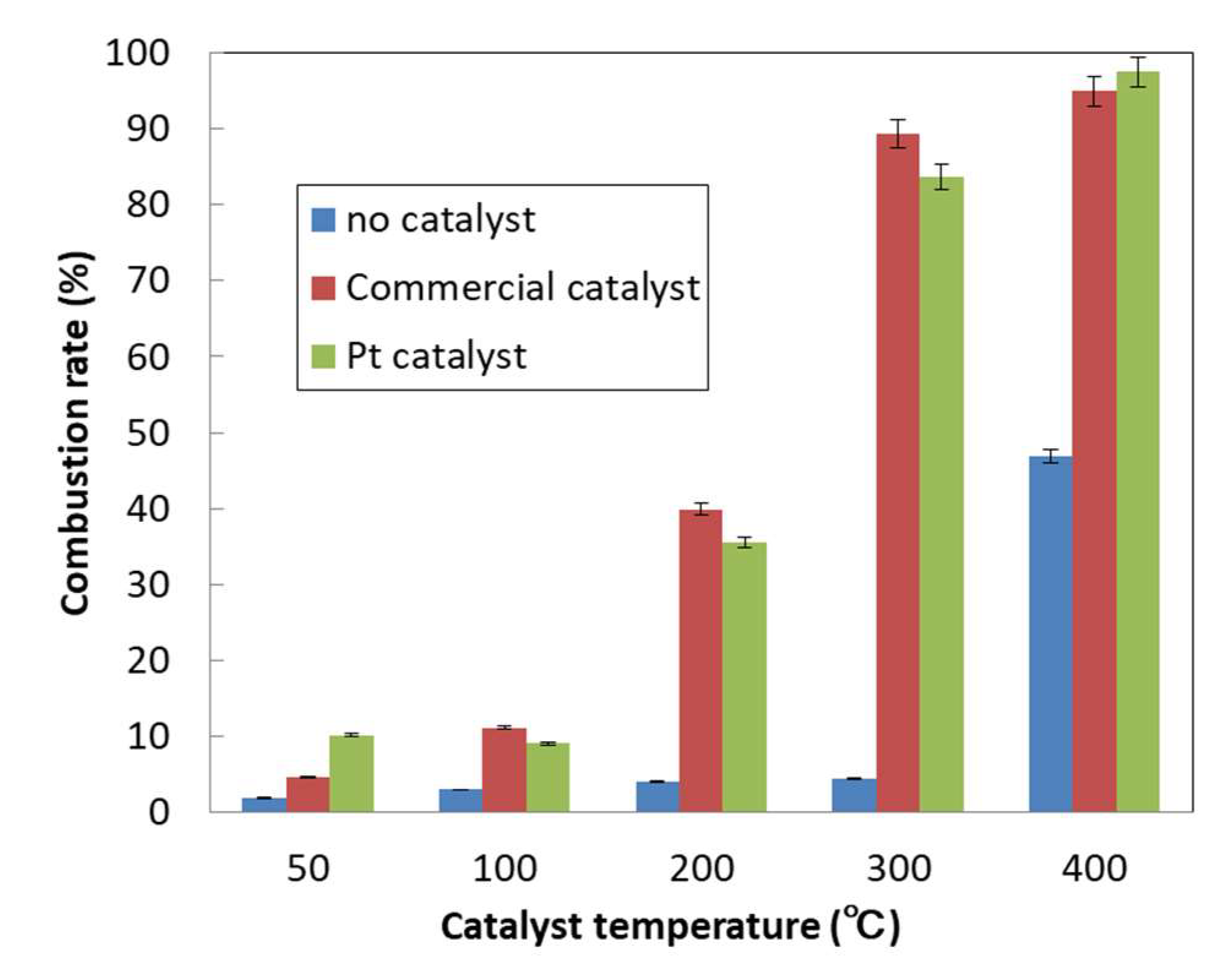
Figure 4 and Figure 5 show the amount of water generated and the octane combustion rates of the catalysts as a function of temperature, respectively. In the absence of a catalyst, the amount of water produced by the combustion of octane remained nearly constant at temperatures up to 300 °C. However, the amount of water generated increased substantially with an increase in temperature to 400 °C. This can be attributed to octane self-burning. Volatile organic compounds (VOCs) typically burn completely to form water and carbon dioxide with an increase in temperature from approximately 750 to 850 °C (direct combustion method) [7]. Thus, at 400 °C, octane acted as a VOC and underwent combustion even in the absence of the catalyst, thus producing a large amount of water. At 200 °C, the amount of water produced in the presence of the catalysts (both the Pt and commercial catalyst) was higher than that produced in the absence of the catalysts. Furthermore, at temperatures ≥300 °C, the catalysts showed no significant change in the amount of water produced. This indicates that the performance of the catalysts could be evaluated at temperatures ≥200 °C. However, the performance of the catalysts saturated at temperatures higher than 300 °C. These results indicate that the performance of the Pt catalysts prepared in this study was comparable to that of the commercial catalyst. As can be observed from Table 2, the Pt catalyst showed a higher octane combustion rate per gram of the catalyst and precious metal particles than the commercial catalyst.
At temperatures of 200 °C or higher, the Pt catalyst showed an octane combustion rate that was approximately 12 times higher per gram than that of the commercial catalyst. On the contrary, the octane combustion rate per gram of the precious metal particles of the Pt catalyst was approximately two times higher than that of the commercial catalyst. Pt and Pd show the same catalytic performance for the combustion of hydrocarbons [8]. However, the performance of 1/12th of the mass of the Pt catalyst prepared in this study was comparable to that of the commercial catalyst prepared using the conventional method. This indicates that the precious metal utilization efficiency of the Pt catalyst was higher than that of the commercial catalyst. These results suggest that the Pt catalyst developed in this study was approximately two times more efficient than the commercially available catalyst. Therefore, the synthesis method used in this study can be applied to prepare catalysts for exhaust gas purification devices used in cars to reduce their weight, size, and cost. However, further investigation is required to evaluate the efficiency of this method in the presence of coke.

3. Materials and Methods

3.1. Preparation of Platinum Catalyst

The glass fiber substrate (manufactured by Masuda Rika Kogyo Co., Ltd.) (Osaka, Japan) was heated at 350 °C for 1 h using an electric furnace to remove organic matter from its surface. After the heat treatment, the glass fiber was ultrasonically cleaned with ethanol for 5 min. After drying, the material was further irradiated under air atmosphere for 10 min using an excimer light irradiation device (Ushio Inc., UER20-172B) (Tokyo, Japan), and the surface was further oxidized with generated ozone to achieve hydrophilization. After the irradiation, the glass fiber was immersed at room temperature for 2 h in a chemical adsorption solution prepared under the conditions listed in Table 3 [9].
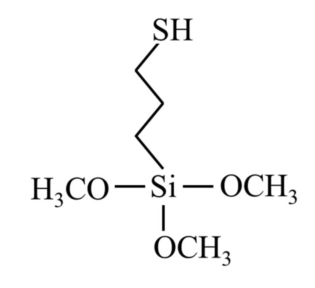
MPTS (Shin-Etsu Chemical Co., Ltd.) (Tokyo, Japan) was used as the chemical adsorbent in this study (Figure 6). After immersion in the chemical adsorption solution, the glass fiber was removed and subjected to ultrasonic washing with ethanol for 5 min to deposit a monomolecular film on its surface. The glass fiber with the monomolecular film was then placed in a sample case and left under air atmosphere for at least 24 h. Finally, the glass fiber was washed with chloroform, acetone, and ethanol, and then dried.
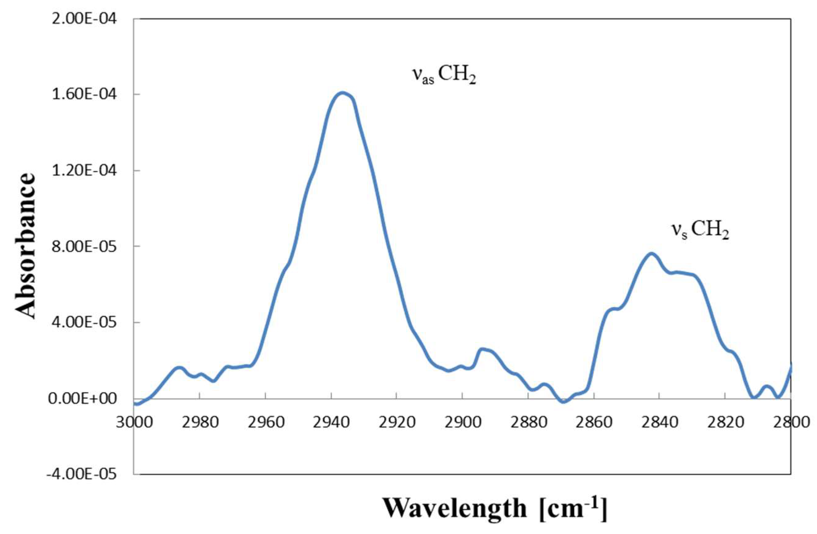
Figure 7 shows the Fourier-transform infrared-reflection absorption spectroscopy (FTIR-RAS) (Massachusetts, USA) profile of the glass substrate with the MPTS film. The absorption peaks corresponding to the carbon chains of MPTS confirm the chemical adsorption of MPTS onto the glass substrate [10]. In order to graft the substrate with Pt particles, it was immersed for 4 h in a dispersion of Pt nanoparticles (manufactured by Shikoku Keisoku Co.; size distribution of the particles is shown in Figure 8) (Kagawa, Japan) (adsorption solvent = ethylene glycol) prepared to a particle concentration of 2.5 wt% [11].
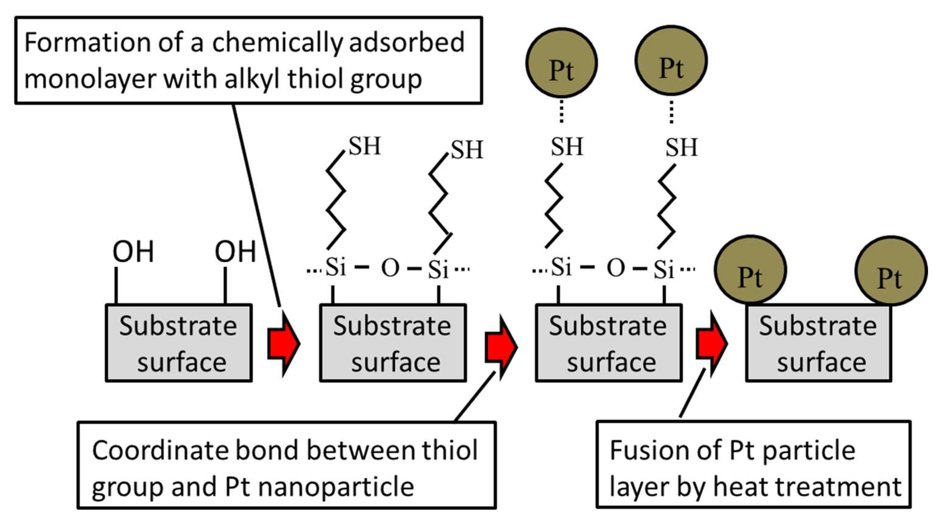
Immersion was achieved by ultrasonically stirring the Pt nanoparticle dispersion using an ultrasonic homogenizer. Then, ultrasonic cleaning was carried out using ethanol to prepare the glass fibers and to graft Pt nanoparticles onto them. Thereafter, the monomolecular film was decomposed and Pt was cured by heating the resulting assembly at 350 °C, using an electric furnace (Tokyo, Japan) under air atmosphere for 30 min. Finally, the catalyst with Pt nanoparticles deposited on the surface of glass fibers was obtained. The schematic of the platinum catalyst preparation process is shown in Figure 9.
The surface morphology of the Pt catalyst was observed before and after the heat treatment by carrying out FE-SEM measurements (Tokyo, Japan) to confirm the grafting of Pt particles. For comparison, the FE-SEM analysis of the glass fibers without the MPTS film was also carried out. In order to measure the weight of the Pt nanoparticles grafted onto the glass fiber surface, the catalyst was added to a hydrofluoric acid aqueous solution (which was handled with the utmost care) [12]. The glass fibers dissolved into this solution and the Pt nanoparticles could be recovered by filtering. The recovered Pt nanoparticles were weighed, and the loading ratio was calculated by measuring the mass of the remaining Pt particles.

3.2. Catalyst Performance Evaluation

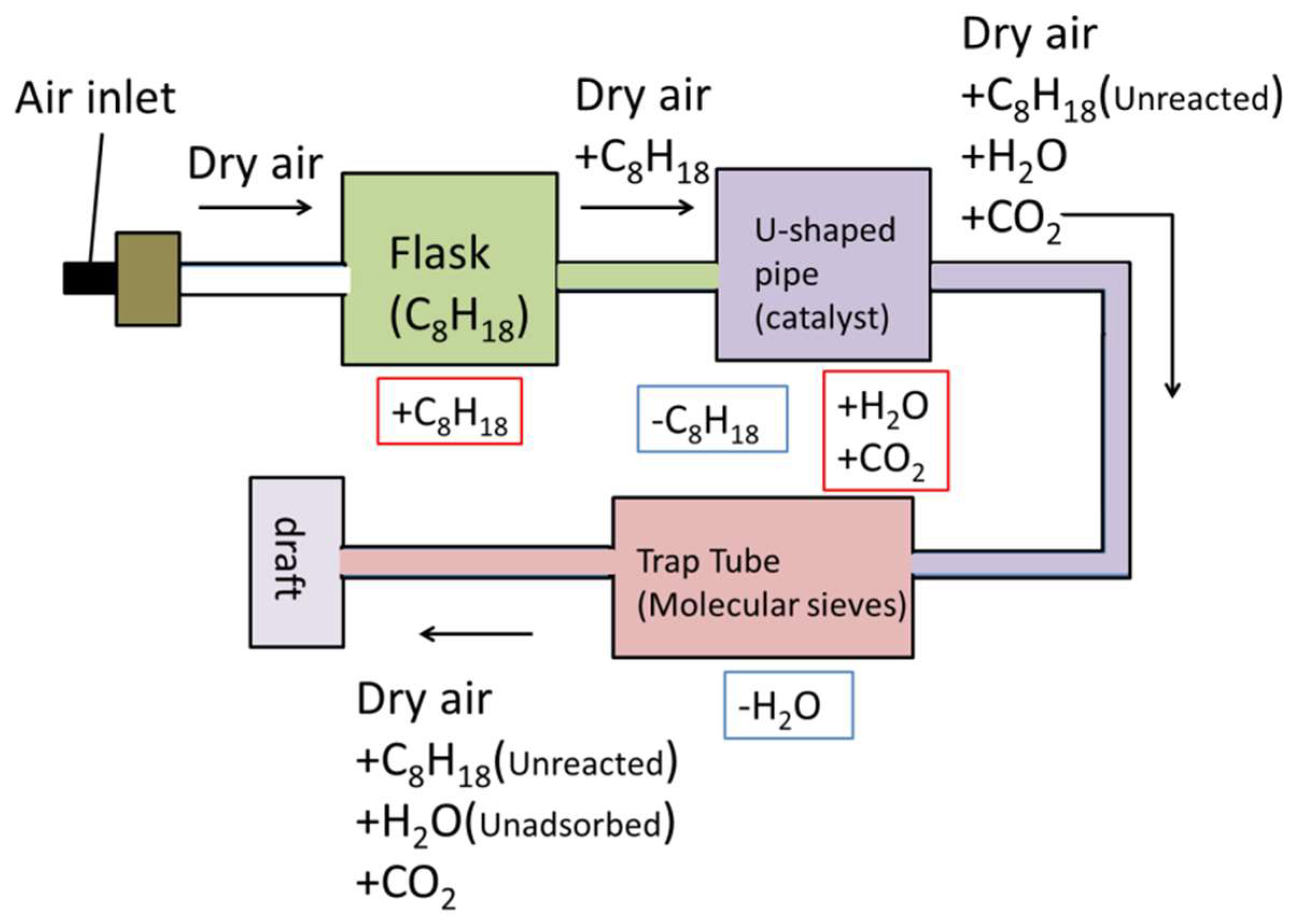
In order to compare the catalyst loading ratio, a commercially available catalyst (Suzuki Corporation, Exhaust Manifold: Precious metal component: Pd) (Nagano, Japan) was dissolved in hydrofluoric acid, concentrated nitric acid, and an aqueous hydrogen peroxide solution. This metal catalyst was then filtered and weighed to calculate its metal loading ratio. Then, tubing was piped so that the gas flowed from the air inlet to the flask, catalyst section, trap pipe, and draft, as shown in Figure 10. In the catalyst section, the Pt catalyst with a measured mass was packed in a U-shaped pipe, which was placed in a mantle heater. The temperature of the mantle heater was controlled using a voltage regulator and thermostat. Furthermore, octane (C8H18) (Osaka, Japan) was introduced into the flask beforehand, molecular sieves were placed in the trap tube and weighed, and dry air (humidity approximately 0.2%) was injected at a flow rate of 0.8 L/min for 90 min from the air inlet. After 90 min, the flow of dry air was interrupted, and the mass of the trap tube containing the octane-containing flask and the molecular sieve weight were measured using an electronic balance. These tests were carried out at 50, 100, 200, 300, and 400 °C. The same experiments were carried out for the commercially available catalyst, the Pd catalyst from Suzuki. Furthermore, the TG–DSC curve of the Pt catalyst was obtained before carrying out the heat treatment to determine the difference between the weight of the catalyst in the presence and absence of the chemically adsorbed monomolecular film. The XRD measurements (Kyoto, Japan) of the catalyst were conducted before and after the heat treatment to confirm the change in the state of Pt.

4. Conclusions

Herein, we proposed a novel method for developing highly efficient Pt catalysts using a reactive chemically adsorbed monomolecular film, Pt nanoparticle dispersion, and glass fiber substrate. The Pt catalyst investigated in this study was prepared by depositing a reactive chemically adsorbed monomolecular film with a thiol group at the molecular terminal on the surface of a hydrophilized glass fiber. The monomolecular film enabled the uniform and dense grafting of Pt nanoparticles on the surface of the glass fiber as a single layer. In addition, the Pt loading ratio of the catalyst was approximately 12.7 wt%. This indicates that the chemically adsorbed monomolecular film on the Pt catalyst could support more platinum than the commercially available catalyst. The catalytic performances of the Pt and commercially available catalysts were evaluated on the basis of their octane combustion rates. Both the catalysts exhibited catalytic performance at temperatures ≥ 200 °C. At 300 °C, the octane combustion rates of the catalysts were 80% or more. Moreover, at 50–400 °C, the octane combustion rates of both the catalysts were approximately the same. Hence, no difference was observed in the catalytic performance of the catalysts. Furthermore, Pt catalysts have been found to exhibit catalytic performance comparable to that of Pd catalysts under lean conditions [6]. In addition, Pt is cheaper than Pd [13]. In this study, we successfully prepared a highly efficient Pt catalyst with superior catalytic performance and lower Pt loading than the commercially available catalyst. The catalyst prepared in this study is a potential candidate for application in car exhaust purification devices as it can reduce the weight, size, and cost of these devices. However, in this study, we evaluated the catalyst performance only on the basis of octane combustion. Hence, further evaluation under a gas atmosphere is also necessary.

Author Contributions

Conceptualization, K.O. and T.O.; Validation, T.S. and Y.H.; Writing—Original Draft Preparation, T.S.; Writing—Review & Editing, K.O. and Y.S.; Supervision, K.O.; Funding Acquisition, K.O. and Y.S. All authors have read and agreed to the published version of the manuscript.

Funding

This work was supported by JSPS KAKENHI, Grant number JP19K05272.

Acknowledgments

We would like to thank Editage (www.Editage.com) for English language editing.

Conflicts of Interest

The authors declare no conflicts of interest.

References

  1. Toshima, N.; Wang, Y. Polymer-protected Cu/Pd bimetallic clusters. Adv. Mater. 1994, 6, 245–247. [Google Scholar] [CrossRef]
  2. Mizukoshi, Y.; Oshima, R.; Maeda, Y.; Nagata, Y. Preparation of Platinum Nanoparticles by Sonochemical Reduction of the Pt(II) Ion. Langmuir 1999, 15, 2733–2737. [Google Scholar] [CrossRef]
  3. Seino, S.; Kinoshita, T.; Nakagawa, T.; Kojima, T.; Taniguchi, R.; Okuda, S.; Yamamoto, T.A. Radiation induced synthesis of gold/iron-oxide composite nanoparticles using high-energy electron beam. J. Nanopart. Res. 2008, 10, 1071–1076. [Google Scholar] [CrossRef]
  4. Kageyama, S.; Sugano, Y.; Hamaguchi, Y.; Kugai, J.; Ohkubo, Y.; Seino, S.; Nakagawa, T.; Ichikawa, S.; Yamamoto, T.A. Pt/TiO2 composite nanoparticles synthesized by electron beam irradiation for preferential CO oxidation. Mater. Res. Bull. 2013, 48, 1347–1351. [Google Scholar] [CrossRef]
  5. Mohamed, R.M. Characterization and catalytic properties of nano-sized Pt metal catalyst on TiO2-SiO2 synthesized by photo-assisted deposition and impregnation methods. J. Mater. Process. Tech. 2009, 209, 577–583. [Google Scholar] [CrossRef]
  6. Ogawa, M.; Sato, R.; Kikuchi, S.; Iwachido, K. Effects of TWC’s PGM Loading Amount on the Exhaust-emission Purification Performance and on the PGM Sintering. Trans. Soc. Automot. Eng. Jpn. 2017, 48, 1015–1020. [Google Scholar] [CrossRef]
  7. Suda, A.; Sobukawa, H.; Suzuki, T.; Kandori, T.; Ukyo, Y.; Sugiura, M. Synthesis of Ceria Zirconia Solid Solution and Performance as Catalytic Promoter. Electron. J. R&D Rev. Toyota CRDL 1998, 3, 3–12. Available online: https://www.tytlabs.com/japanese/review/rev333j.html (accessed on 18 March 2018).
  8. Akama, H. Study on Effective Removal of Residual Methane in Wasted Gas originated from the Fuel Reforming Gas by Catalytic Combustion. J. Combust. Soc. Jpn. 2010, 52, 76–85. [Google Scholar] [CrossRef]
  9. Tsuji, I.; Ohkubo, Y.; Ogawa, K. Study on Super-Hydrophobic and Oleophobic Surfaces Prepared by Chemical Adsorption Technique. Jpn. J. Appl. Phys. 2008, 48, 040205. [Google Scholar] [CrossRef]
  10. Ogawa, K.; Mino, N.; Nakajima, K.; Azuma, Y.; Ohmura, T. Studies of molecular alignments of monolayers deposited by a chemical adsorption technique. Langmuir 1991, 7, 1473–1477. [Google Scholar] [CrossRef]
  11. Sawada, S.; Masuda, Y.; Zhu, P.; Koumoto, K. Micropatterning of copper on a poly(ethylene terephthalate) substrate modified with a self-assembled monolayer. Langmuir 2006, 22, 332–337. [Google Scholar] [CrossRef] [PubMed]
  12. Murahashi, S.; Sakakibara, S. Anhydrous hydrogen fluoride as solvent. J. Synthetic Org. Chem. Jpn. 1967, 25, 1176–1191. [Google Scholar] [CrossRef] [Green Version]
  13. Tanaka Kikinzoku Kogyo Co., Ltd. Latest Precious Metal Market Trends. Available online: https://pro.tanaka.co.jp/library/rate/ (accessed on 15 October 2019).
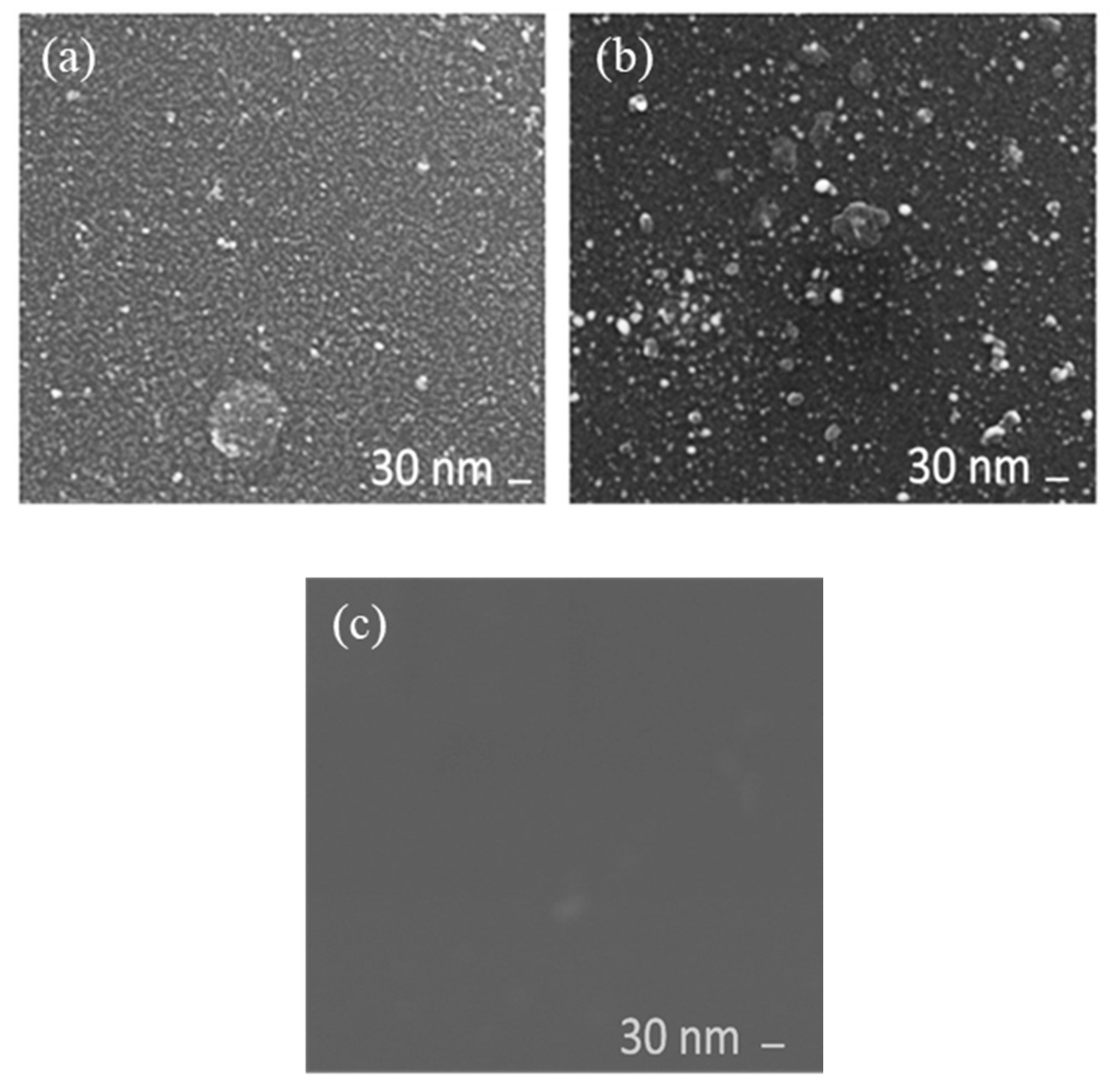
Figure 1. FE-SEM images of the Pt catalyst on the glass fiber substrate: (a) before curing, (b) after curing, and (c) on the glass fiber substrate without the 3-mercaptopropyltrimethoxysilane (MPTS) monolayer after the Pt nanoparticle treatment.
Catalysts 10 00472 g001
Figure 2. Thermogravimetry–differential scanning calorimetry (TG–DSC) curves of the Pt catalyst.
Catalysts 10 00472 g002
Figure 3. XRD patterns of the Pt catalyst before and after the heat treatment.
Catalysts 10 00472 g003
Figure 4. Amount of water produced by the combustion of octane as a function of the catalyst temperature.
Catalysts 10 00472 g004
Figure 5. Combustion rate of octane for the catalysts as a function of the catalyst temperature.
Catalysts 10 00472 g005
Figure 6. Chemical structure of MPTS.
Catalysts 10 00472 g006
Figure 7. Fourier-transform infrared-reflection absorption spectroscopy (FTIR-RAS) profile of the MPTS monolayer adsorbed on the glass plate.
Catalysts 10 00472 g007
Figure 8. Particle-size distribution of the Pt nanoparticles.
Catalysts 10 00472 g008
Figure 9. Schematic of the Pt catalyst preparation process.
Catalysts 10 00472 g009
Figure 10. Schematic of the device used for evaluating the catalyst performance.
Catalysts 10 00472 g010
Table 1. Precious metal loading rates (precious metal particle weight/catalyst weight × 100) of the catalysts.
-Catalyst Weight (g)Precious Metal Particle Weight (g)Loading Rate (wt%)
Pt catalyst0.0470.006012.7
Commercial catalyst sample0.97220.01651.7
Table 2. Precious metal nanoparticle utilization efficiency of the catalysts.
Heating TemperatureCombustion Rate of Octane per g of Catalyst (%)Octane Combustion Rate per g of Precious Metal Particles (%)
-Commercial CatalystPt CatalystCommercial CatalystPt Catalyst
502.256.297.8466.3
1005.149.9232.4414.2
20018.3195.3825.51620.3
30040.9460.71848.53822.5
40043.5536.41964.74450.6
Table 3. Conditions for preparing the adsorption solution.
-ChemicalsConcentrationAmount
SolventAqua solvent G-21 (Aqua Chemical Co., Ltd., Chuo-ku, Japan)Undiluted50 mL
Adsorbent3-mercaptopropyltrimethoxysilane (MPTS) (dehydrated chloroform dilution)0.1 M76.5 μL
CatalystTetra chlorosilane (TCS) (dehydrated chloroform dilution)0.01 M2.5 mL