Review

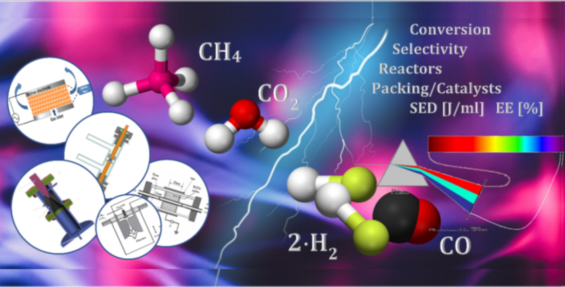
Non-Thermal Plasma for Process and Energy Intensification in Dry Reforming of Methane

by
Rufat Sh. Abiev
1,*,
Dmitry A. Sladkovskiy
2,
Kirill V. Semikin
2,
Dmitry Yu. Murzin
2,3 and
Evgeny V. Rebrov
1,4,5
1
Department of Optimization of Chemical and Biotechnological Equipment, St. Petersburg State Institute of Technology (Technical University), St. Petersburg 190013, Russia
2
Resource-Saving Department, St. Petersburg State Institute of Technology (Technical University), St. Petersburg 190013, Russia
3
Laboratory of Industrial Chemistry and Reaction Engineering, Åbo Akademi University, FI-20500 Åbo (Turku), Finland
4
School of Engineering, University of Warwick, Coventry CV4 7AL, UK
5
Department of Chemical Engineering and Chemistry, Eindhoven University of Technology, P.O. Box 513, 5600 MB Eindhoven, The Netherlands
*
Author to whom correspondence should be addressed.
Catalysts 2020, 10(11), 1358; https://doi.org/10.3390/catal10111358
Submission received: 2 October 2020 / Revised: 6 November 2020 / Accepted: 17 November 2020 / Published: 22 November 2020

Abstract

:
Plasma-assisted dry reforming of methane (DRM) is considered as a potential way to convert natural gas into fuels and chemicals under near ambient temperature and pressure; particularly for distributed processes based on renewable energy. Both catalytic and photocatalytic technologies have been applied for DRM to investigate the CH4 conversion and the energy efficiency of the process. For conventional catalysis; metaldoped Ni-based catalysts are proposed as a leading vector for further development. However; coke deposition leads to fast deactivation of catalysts which limits the catalyst lifetime. Photocatalysis in combination with non-thermal plasma (NTP), on the other hand; is an enabling technology to convert CH4 to more reactive intermediates. Placing the catalyst directly in the plasma zone or using post-plasma photocatalysis could generate a synergistic effect to increase the formation of the desired products. In this review; the recent progress in the area of NTP-(photo)catalysis applications for DRM has been described; with an in-depth discussion of novel plasma reactor types and operational conditions including employment of ferroelectric materials and nanosecond-pulse discharges. Finally, recent developments in the area of optical diagnostic tools for NTP, such as optical emission spectroscopy (OES), in-situ FTIR, and tunable diode laser absorption spectroscopy (TDLAS), are reviewed.

Graphical Abstract

1. Introduction

Natural gas is an abundant, cheap, and underutilized resource with increasing proved reserves. It is mainly used as a source of energy for heating and power generation. Methane is the principal component of natural gas with a volumetric fraction of more than 75% [1]. Increasing worldwide energy demands with the discovery of huge shale deposits stimulated extensive research in the conversion of natural gas to high-value transportation fuels and chemicals.
On the other size, CO2 is increasingly utilized in many applications. For example, in Iceland, a pioneering CO2 to methanol plant using locally available cheap geo-thermal energy has been built by Carbon Recycling International company. In Canada, Blue Fuel Energy will build a CO2 to methanol plant with a capacity of 400,000 tons per year, powered by renewable electricity [2].
Conventional thermo-catalytic approaches focus on converting methane to syngas [3,4], ethane and ethylene [5], or C1 oxygenates [6]. It should be mentioned that along with commercially used technologies (like e.g., steam and autothermal reforming methane to syngas) some other promising methods are on the lab-scale level (such as dry reforming or methane coupling). High temperature (>600 °C) is used in dry reforming reactors to facilitate reactions, leading to severe coke formation and a relatively low yield of the desired products. A close to equilibrium yield is easily attainable over a wide range of catalysts.
Photo- and plasma catalysis are potential technologies to enable methane activation to more reactive intermediates. These technologies are also studied for their application towards CO2 reduction to fuels and chemicals. Although the direct use of solar energy to convert CO2 and/or CH4 is feasible via photocatalytic processes, low conversion efficiency and limited use of the full solar spectrum are major drawbacks of this approach. While this is an attractive option, the main problems are related to the low productivity and the combined (in a single compartment) formation of products of reduction and oxidation, creating issues of safety (creation of explosive mixtures in a reaction compartment) as well as high costs of separation. Although many research groups are working in this direction, the industrial applications of this method are foreseen only in a rather distant future. Conventional photocatalytic reactions occur at a gas-solid interface and therefore limited by available surface area. Often, liquid products can form a film that prevents the efficient mass transfer of gas molecules to the surface. Furthermore, the light intensity decreases with increasing the thickness of the photocatalytic layer. Therefore reaction interface engineering is highly desirable to understand in order to enhance the photocatalytic kinetics. However, it has received relatively little attention with respect to catalyst design [7]. Therefore in the present form, photocatalytic processes are relatively inefficient and, thus, are unlikely to compete with large-scale industrial chemical processes in short and midterm. However, their ability to produce fuels paves the way for the potential storage of solar energy, which could not be utilized otherwise [8,9].
Another alternative approach is to apply solar radiation to provide the heat (above 1200 °C) for CO2 decomposition reaction to generate CO (or CH4 decomposition reaction to generate H2), rather than to generate charge separation and photoinduced electrical current. A concept of concentrated solar power (CSP) plants with metal oxides was a hot research topic a few years ago. Despite many research problems were solved, many others remained and those are related to limited production scale, material stability at high temperatures, and high equipment costs. These factors strongly hinder further development beyond the pilot plant scale, and current interest on this route is decreasing.
Plasma assisted catalysis, on the other hand, is able to convert large amounts of CO2 and CH4 via electrical energy attracting significant attention due to its mild operating conditions and unique advantages in activating inert molecules. Because of the non-equilibrium characteristics, non-thermal plasma (NTP) promotes thermodynamically unfavorable chemical reactions to occur at relatively low temperatures [10]. However, due to high reactivity of plasma, producing a diversity of activated species, radicals and ions, the process lacks selectivity towards the specific end products. Placing the catalyst directly in the plasma zone or using post-plasma catalysis could generate a synergistic effect to increase the formation of the desired products. The synergistic effect between NTP and the catalyst on the yield of liquid fuels chemicals was previously reported in dry reforming of methane (DRM) [11].
Over the last 5 years, several reviews covering CH4 activation in plasma have been published. Chung and Chang discussed plasma-catalysis interactions in DRM reaction and possible synergy mechanisms [12]. The review of Puliyalil et al. made an overview of different reaction pathways, related to the partial oxidation steps of CH4 and CO2 as well as CO2 reduction with H2, CH4 or other paraffin species to syngas [13]. Shao et al. published a review on the application of nanosecond pulsed discharges for the activation of small molecules [14]. Recent progress on the mechanism of nanosecond-pulse discharge based on runaway electrons and related measurement technology was discussed and the characteristics of three typical discharges, including direct-driven pulsed discharge, pulsed dielectric barrier discharge and pulsed plasma jet, were reviewed. The authors argued that classical Townsend and streamer theories cannot be applied to pulsed discharge.
Our paper aims to provide a view on the future development for a scientist or an engineer who wants to understand the role of plasma technology in the new scenario of distributed energy production for a sustainable and low-carbon economy. Therefore, first, we introduce the current state-of-the-art and the potential of CH4 conversion technologies. This section is a snapshot of current research activities in different research groups and it is not intended to give a complete picture over current (thermos-chemical) methods of CH4 activation. Then the paper describes main plasma reactor types used in the DRM reaction with a detailed view on the application of dielectric barrier discharge reactors. This is followed by an overview of applications of ferroelectric and/or catalytic materials and examples of synergistic effects between NTP and relevant catalysts. Photocatalysis is often considered as an important step towards further developments in the plasma-catalysis field. Therefore, we introduced a section describing photocatalytic applications for CH4 activation. Finally, the recent developments in the area of plasma diagnostic methods are reviewed and discussed. In the outlook section, we discussed the potential benefits of plasma-based CH4 conversion and its impact on distributed energy production and climate change.

2. State of the Art in DRM

2.1. Conventional Thermo-Catalytic Methane Dry Reforming

DRM is a highly endothermic reaction requiring high energy input. The process temperature occurs typically above 700 °C, and in some cases even at high T as 850 °C [15]. At the same time, there is no direct involvement of oxygen leading to carbon deposition on the catalyst surface [16]. Possible reactions involved in the DRM process are listed below [17]:
CH4 + CO2 ↔ 2 CO + 2 H2     + 247 kJ mol−1
CO + H2 ↔ H2O + C    − 131.3 kJ mol−1
CO2 +2 H2 ↔ C + 2 H2O    − 90 kJ mol−1
CH4 ↔ C+2 H2    + 74.9 kJ mol−1
2 CO ↔ C+ CO2    − 172.9 kJ mol−1
CO2 + H2 ↔ CO + H2O    + 41 kJ mol−1
Besides hydrogenation of CO (entry 2) and CO2 (entry 3) leading to coke, the later can also be produced by the decomposition of methane (entry 4) or the Boudouard reaction (entry 5). The main challenge is, therefore, to suppress the undesired reactions by application of more selective catalysts [18,19].
Different solid catalysts used in DRM and the related reaction conditions are listed in Table 1. For more information on thermo-catalytic the reader is referred to several reviews available in the literature [20,21,22] In general, noble metal catalysts (namely, Pt, Ru, and Rh) provide enhanced lifetime with a high catalytic activity [23]. Nonetheless, even for Pt on alumina catalysts, deactivation remains significant [24]. The addition of small amounts of ceria along with Pr, Zr or Nb as dopants to Pt/Al2O3 catalyst improved the catalyst lifetime, at the expense of much higher catalyst costs.
Industrially preferred Ni- and Co-based catalysts have been extensively studied from the viewpoint of selecting suitable promoters, catalyst supports, as well as preparation methods and the optimal metal content [20,21,22]. The effect of different supports, such as Al2O3, SiO2, MgO, TiO2 and ZrO2, on the activity of supported Ni catalysts was investigated [25]. A Ni/TiO2 catalyst showed the highest reaction rate, with the activity decreased as follows: SiO2 < MgO < Al2O3 < ZrO2 < TiO2.
The catalyst deactivation by rapid coke deposition was diminished by an addition of reducible supports to Ni catalysts enhance the oxygen storage capacity and thus the catalyst lifetime. Due to their basicity and high oxygen storage capacity, reducible oxides such as CeO2 and La2O3 decreased the coke deposition rate and improved the catalytic lifetime [26,27]. A 5 wt.% CeO2/25 wt.% Ni/Al2O3 composite catalyst, prepared by ultrasonic-assisted co-precipitation, was stable during 15 h on-stream [27]. Addition of rare-earth elements further improved the catalytic activity of Ni catalysts. The largest positive effect was achieved with an addition of Ce, followed by Pr and Y. The smallest effect was observed with the addition of Sc, yet the catalyst was still more active compared to the unpromoted one. The carbon deposition decreased by 25% over Ce-promoted catalysts due to enhanced surface basicity and higher Ni dispersion. In addition, both Ce- and Pr-modified catalysts demonstrated fast redox behavior that involved the reversible formation of Ce3+/Ce4+ and Pr3+/Pr4+ redox pairs, facilitating their decoking.

2.2. Application of Non-Thermal Plasma and Catalysis for DRM

Due to very high stability of CO2 and CH4 molecules, it is impossible to convert them directly into liquid products in one-step catalysis. In this context NTP offers a unique way to enable thermodynamically unfavorable chemical reactions at low temperatures owing to the non-equilibrium character of plasma. Non-thermal plasma is created by applying electricity to a gas. The electrons are heated by the electric field applied, and they can activate CH4 molecules by excitation, ionization, and dissociation, creating the reactive species and allowing chemical reactions to occur at near ambient temperature and pressure. While non-thermal plasma is already applied on an industrial scale in waste incineration and ozone manufacturing, its use in CH4 activation to obtain fuels and chemicals, is limited to the laboratory scale. Currently, NTP is seen as an enabling technology for the future of sustainable energy, where chemical processes will be based on renewable sources rather than on fossil fuels [37].
The first application of NTP for DRM reaction was reported by Capezzuto et al. [38]. They used a radiofrequency (RF) plasma reactor to conduct the reaction under a low pressure of 20 Torr and observed that acetylene was the main reaction product. However, low-pressure plasma is not economical for industrial applications due to the high costs of vacuuming and low flow rates. Therefore, subsequent studies were focused on atmospheric-pressure DRM via gliding arc (GA) discharge. The GA plasma produced a mixture of C2H2, C2H4, CO and H2 [39]. In atmospheric pressure plasma DRM process, the energy for electronic ionization is very high, therefore the overall efficiency strongly depends on the possibility of secondary electron formation in the electron collision step.
Another type of reactors studied is a corona discharge [40]. The discharge can be induced between two symmetric or asymmetric electrodes via AC (for symmetric) or DC (for both cases) power supply and it was also applied for methane activation [41]. Acetylene was the major by-product, and selectivity to CO was typically higher than to H2 indicating that hydrocarbon formation plays an important role in the corona discharge process [42,43,44,45].
The dielectric barrier discharge (DBD) plasma reactor was first reported by Siemens et al. to generate ozone [46]. In this reactor, there is a dielectric layer between the two electrodes. High selectivity to hydrocarbons was attributed to the partial dissociation of CH4 that gives large amounts of CHx radicals (x = 1 − 3), which further recombine to form C2H6 and C2H4 [12]. A possibility of one-step NTP reforming of CO2 and CH4 into liquid fuels and chemicals was considered to replace the indirect route which normally requires at least two steps. The first step is to produce syngas (CO and H2) which is very similar to thermal methane activation described in Section 1 This is followed by the conversion of syngas into oxygenates in a downstream reactor over platinum group metal (PGM) catalysts (Scheme 1) [10].

2.3. Dissociation Mechanisms in Different Plasma Reactors

During the discharge, the electrons with a relatively high kinetic energy of about 10 eV form microfilaments. While this energy is considerably higher than in other non-thermal plasmas, its major part dissipates via the dielectric layer resulting in low energy efficiency [11,47,48]. In atmospheric-pressure plasma, the density of electrons with high kinetic energy is relatively low to induce direct dissociation of CH4 and CO2, requiring 9 and 11 eV, respectively [49,50]. The dissociation of both CH4 and CO2 occurs, therefore, stepwise (Equations (7)–(12)). When vibrational levels of CO2 molecules are excited by plasma, the kinetic energy of electron impact dissociation reduces to from 11 to 5.5 eV [41]. Therefore, excitation of CO2 vibrational level to induce dissociation is an important activation channel in plasma. Several electron impact channels (Equations (8)–(10) and (12)) result in CO2 dissociation [50,51,52]. During an electron impact excitation, several excited states of CO2 are generated (Equations (7) and (11)) [52].
e + C O 2 ( X 1 g + )   e + C O 2 ( 1 1 g + )
e + C O 2 ( 1 1 u + )   e + C O ( X 1   + ) + O ( 1 S )
e + C O 2 ( X 1 g + )   e + C O ( a 3   ) + O ( 5 S )
e + C O 2 ( X 1 g + )   e + C O 2 ( 001 )
e + C O 2 ( 001 )   e + C O ( X 1   + ) + O ( 1 S )
Direct electron impact dissociation proceeds through a dissociative electronically excited state. On the contrary, vibrational excitation requires significantly less energy. Once the lowest vibrational levels are populated, they can gradually populate the higher vibrational levels by vibrational-vibrational (VV) collisions. This process, so-called “ladder-climbing” requires the minimum amount of 5.5 eV for CO2 dissociation, providing a more efficient dissociation pathway. The process can be exploited in MW and GA reactors at either reduced pressure or during pulsed plasma operation. This can considerably improve the EE in these plasma types. However, the vibrationally excited species lose their energy upon collision with ground-state molecules. The latter process is called vibrational-translational (VT) relaxation. It depopulates the vibrational levels, and therefore detrimental for energy-efficient conversion by the ladder-climbing pathway. The VT process heats up the gas, while its rate increases with temperature, creating a positive feedback mechanism, which is difficult to control. VT relaxation appears to be quite important in GA plasmas, explaining their high gas temperature (often 3000 K and above). For this reason, GA plasma is also called “warm plasmas,” as its temperature is in between those of NTP such as DBD, which operate typically at room temperature, and thermal plasmas, where the gas temperature can reach 10,000 K, which is the same as the electron temperature. In GA plasma reactors, the electron temperature is higher than the gas temperature, however, the vibrational and gas temperature are close to each other (i.e., vibrational-translational equilibrium is achieved).

2.4. Configurations of Plasma Reactors

While the performance of various plasma types is already competitive with other emerging technologies such as electrochemistry, plasma-assisted CH4 (and/or CO2) conversion is carried out at the laboratory scale and is not implemented in industrial processes. Different types of plasma reactors are being investigated for DRM, including dielectric barrier discharge, microwave, gliding arc plasmas, glow discharges, nanosecond pulsed discharges, corona and spark discharges. They differ in the way the electricity is applied and the value of the electric field, reactor configuration, operation pressure and power. Various reactor designs are briefly summarized in Table 2.
A point-to-point reactor was made of the Pyrex tube (12 mm i.d., 15 mm o.d, 80 cm length) and two stainless steel sharp electrodes, positioned on the opposite ends of the tube [53]. The voltage was fixed at 17 kV. A CO2/CH4 mixture was fed at a flow rate of 200 mL/min at a 1 bar pressure [53]. A spark discharge reactor [54] consisted of a rotary stainless steel disc (30 mm o.d, 3 mm thickness) as the ground electrode and a stainless steel tube (1 mm i.d., 2 mm o.d.) as a high-voltage electrode. The electrodes were placed in a quartz tube (100 mm o.d.) at a distance of 6 mm. The reactor operated at an AC voltage of 5 kHz. The gas was fed via the tubular electrode. A spark discharge reactor was made of a quartz tube (o.d. 24 mm, 36 cm length) [55]. One electrode was the stainless steel tube (3 mm i.d., 6 mm o.d.), while the other electrode was a stainless steel rod (8 mm o.d) positioned at a distance of 8 mm. A CH4/CO2 mixture with a molar ratio of 2 was fed at a flow rate of 100–200 mL/min. A quartz holder was positioned inside the tube to accommodate a catalyst (2 g). A DC pulse operation at 16 kV with a pulse rising time between 25 and 100 μs was studied. In a similar configuration presented in [12]. A BZT ferroelectric layer (0.5 g) was positioned between the two electrodes positioned at a distance of 5 mm from each other. The reactor operated at DC pulses of 20 kV. A GHSV has varied in the range of 8500–85,000 h–1. A DBD reactor with an annular channel with mesh electrodes was demonstrated in [56]. The reactor consists of two coaxial quartz tubes covered with stainless steel mesh electrodes. The high voltage electrode was positioned in the center, and the outer electrode was grounded. The length of the discharge region was 55 mm with a discharge gap of 3 mm. A CH4/CO2 mixture with a molar ratio of 1 was fed at a flow rate of 25–100 mL/min. The reactor operated at a peak-to-peak voltage of 24 kV and a variable frequency of 30–40 kHz. A different design of a coaxial DBD reactor was presented in [57]. In this reactor, the center electrode was grounded while the outer electrode was connected to an AC high voltage output (40 kV). The discharge region was 90 mm. The reactant flow rate was 50–300 mL/min. The electrodes were cooled with water. A cylindrical dielectric tube (10 mm i.d, 40 cm length) with an aluminum mesh was used in a coaxial DBD reactor in [58]. A stainless steel rod was used as the center electrode.
An AC gliding arc plasma reactor operating at 10 kV was demonstrated in [59]. Two semi-ellipsoidal aluminum electrodes (50 mm long, 30 mm wide) were fixed in an insulating housing and symmetrically placed on both sides of a gas nozzle with a diameter of 1.5 mm. A 3D cylindrical tornado electrode (3D-CTE) with the shape of the conical diffuser (2 mm o.d.) provided higher efficiency for interactions between the plasma species and the reactants [60]. A needle electrode was placed in the middle of the reactor. The gap between the tip of the needle electrode and the throat was 0.6 mm. The plasma was created with an AC power supply operated at 4–8 kV at a frequency of 50 Hz.
It can be concluded that the three most common plasma types are DBD, spark, and GA plasma reactors. The two electrodes can be parallel plates, but for CH4 conversion, a cylindrical configuration in which the two electrodes are concentric cylinders, is desirable as it minimizes the amount of gas bypassing the plasma zone. DBD reactors have a rather simple design, which makes it easy for upscaling and industrial applications. In addition, the simple design allows the implementation of catalysts and ferroelectric materials inside the reactors in order to improve the selectivity towards high added value chemicals and reaction rate.
In a GA plasma reactor, an electric potential difference is applied between two flat diverging electrodes. An arc is created at the shortest distance near the gas inlet, and it glides towards the reactor outlet carried by gas flow until it extinguishes. Then a new arc is created again at the shortest distance and the process continues. A GA reactor operates at atmospheric pressure, and exhibits quite good energy efficiency.
A spark plasma arises when applying electric power between two point electrodes in the space filled with gas. The gas temperature can easily rise to above 4000 K which makes the application of catalysts possible only in post-plasma mode (as it will be discussed in the next sections).

3. Characteristics of Plasma Reactors

3.1. Main Efficiency Parameters

The energy efficiency (EE) is defined as the total syngas generated per kilowatt-hour input (Equation (13)) to compare the syngas generation efficiency for different plasma reactors [61]:
E E ( mol kWh ) = n H 2 + n C O t P = 3.6 P F V R T p ,
where n is the number of products, P is the electric power, t is discharge time, p is the pressure, FV is the volumetric flow rate, T is the temperature, and R is the ideal gas constant. The EE can also be expressed in grams of H2 per kWh or %. Expressing EE in percentage is a common method to estimate chemical energy efficiency based on the reactant conversion, total power supplied to the system and the heat of the target DRM reaction [61]:
E E ( % ) =   ( n C H 4 ) c o n v e r t e d × Δ H 298 P ,
where Δ H 298   =   247 kJ/mol.
An EE research target of 60% was defined by Snoeckx and Bogaerts [62] based on the comparison with electrochemical water splitting, being the main competitor of plasma conversion for storing renewable energy, and already reaching commercial energy efficiencies of 65–75%. A comparison with other novel technologies for CO2 conversion, which directly use solar energy (solar thermochemical conversion with a solar-to-fuel conversion efficiency of 20%) requires a plasma-based CO2 conversion with an EE of 60–80% to get an overall solar-to-fuel efficiency of 15–20%.
Another useful parameter, the specific energy density (SED), is defined as the average power dissipated in the discharge divided by the total gas flow rate. The discharge power (P) is calculated by the effective voltage (U) multiplied by the current (I) (Equation15):
S E D ( J L ) = P F V = U max I 2 F V
It can be seen that the SED is a reciprocal function of EE, expressed in different units: Liter instead of mol and Joule instead of kWh. Increasing the flow rate usually results in higher EE in warm plasma types (corona, GA, spark) because of more chance for impact dissociations utilizing high energy electrons (Figure 1). However, the too-high flow rate decreases the EE because the secondary electron production is decreased. Selectivity to H2 and CO is almost independent of the flow rate [41].
The local electric field near the contact point between the pellets can be 10–104 times higher than that in a spherical void. The average electric field (E) inside a spherical void and the corresponding electron density (number of electrons in the reactor volume, ne) are expressed by Equations (16) and (17), respectively [63].
E V d 3 ε p 2 ε p + ε g
n e P V α A e μ 0 E 0 ω E 1 ω P V α A e μ 0 E 0 ω ( V d 3 ε p 2 ε p + ε g ) 1 ω ,
where V is the voltage, d is the gap size between the electrodes, εg and εp are the dielectric constants of the background gas and the pellets, respectively, α and A are the void fraction and cross-sectional area of the reactor, respectively, e is the electric charge of electrons (e = 1.6 × 10⁻¹⁹ C), μ0 is the electron mobility at the reference electric field E0, and ω is an empirical coefficient, which depends on the gas properties. For example, ω is equal to 0.501 and 0.198 for air and nitrogen, respectively [64]. It can be seen from Equation (16), that the electric field has a minimum value (Ex ≈ V/d) when εg ≈ εp 1.
The gamma value, being the normalized capacitance γ = (Cdiel − ζdiel)/(Cdiel − Ccell), where Cdiel and Ccell are the electrical capacitances of the reactor, defined from its geometry, ζdiel is an effective capacitance, represents the areal fraction of the electrodes that is not discharging. A value of zero (γ = 0) indicates complete charge bridging in the reactor, and a value of γ = 1 indicating no charge bridging (i.e., no plasma present). With increasing voltages, the gamma value generally tends to decrease from 1 to 0 at the highest applied voltages [65]. This rapid decrease in gamma is due to a charge being transferred across the gap, rather than being ‘trapped’ by the pellet. In a packed bed reactor, each packing pellet acts as an individual capacitor and can therefore trap charges.

3.2. The Effect of Reduced Electric Field on the DRM Reactor Choice

The influence of the reduced electric field E/n (Td = Townsend, 1 Td = 10−21 V⋅m2) on the electron energy loss deposited into relevant excitation, dissociation, or ionization channels of N2 and CO2 in reactors is shown in Figure 2 [66]. As an example, in a nitrogen plasma, a reduced electric field of 100 Td corresponds to average electron energy of approximately 2 eV. It can be seen from Figure 2 that a significant fraction of the energy is converted into the internal energy of rotational and vibrational excitations at low electric fields, while the higher-energy electronic excitation, ionization, and dissociation channels become significant at reduced electric fields of 100 Td or above. It is worth to mention that the level of 100 Td corresponds to a DBD regime (dashed vertical lines in Figure 2 indicate E/n values demarking the onset of the DBD regime). It can be seen that the efficiency of vibrational excitations is close to zero in a DBD regime, whereas the electronic excitation has a maximum at 200 Td. This explains the low values of EE as listed in Table 3.
It can be seen in Figure 2, a reduced electric field of about 50 Td is ideal for vibration-induced dissociation. This value is typically observed in the microwave and GA plasma reactors, which explains their high EE. However, DBD reactors operate in the higher E/n range. Therefore, it is necessary to lower the reduced electric field in DBD reactors to values below 100 Td. In theory, this can be done in two ways: (i) by lowering the applied electric field (E) or (ii) by increasing the number of electrons in the reactor volume (n). The applied electric field is determined by the power source. As such applying lower power may be beneficial, although the power should be sufficient to create a stable plasma. However, this approach would not always create a lower electric field, as the CH4 DBD plasma is typically filamentary. Therefore, lower power may also create fewer filaments instead of a lower electric field in these filaments. Thus, it is not straightforward to control the E/n value in a DBD plasma reactor [67].
The microwave (MW) plasma is seldom employed in the DRM reaction (Table 4). Hrycak et al. [68] conducted experiments with microwave pulsed plasma for syngas production using a mixture of CH4 and CO2 at a molar ratio of 0.66. The optimum H2 production rate was 156 g/h at a power input of 7.5 kW. An EE of 21 g/kWh (EE = 7.2%) was reported at a CH4 conversion of 80%. The highest yield of 43 g(H2)/kWh was reported when water vapor was fed in the plasma region [69]. The performance was enhanced with the implementation of a CH4 recycling loop [70]. However, the yield was still rather far from the US Department of Energy (DOE) set a target for H2 production of 60 g/kWh which is needed for a large scale industrial implementation [71].

4. Dielectric Barrier Discharge Reactors

Dielectric barrier discharge (DBD) is the most popular type of plasma reactors used for DRM in the past, partly due to its simple design, easy scalability and its affordability for pilot-scale research [72,73]. The conversion and EE depend on the applied power, specific energy input, operating pressure and temperature. Introduction of the inert gas such as helium, argon and nitrogen as well as a catalyst can improve yields of hydrogen and CO (syngas route) and different hydrocarbons [74,75].

4.1. AC Mode

Usually, the DBD reactors operate in the so-called filamentary mode when the gas excitation occurs in the discharge volume by stochastically distributed microdischarge channels of 0.1–1 mm in diameter that appear during each half-period of the applied AC voltage. There is a good understanding of the physical mechanisms involved in the DBD operation. However, the literature lacks kinetic information about some of the individual steps involved. There are also no detailed models of plasma chemical reactors accounting for a complex microdischarge channels structure and convective heat and mass transport by the gas flow.
Snoeckx and Bogaerts [62] summarized recent research data for DRM obtained in DBD reactors for both packed and unpacked configurations. The results are shown in Figure 3 where the energy costs are shown as a function of conversion. It can be seen that the energy cost decreases with an increasing total conversion for the packed DBD reactor on the contrary to the non-packed discharge.
Wang et al. [76] reported a conversion for CH4 (and CO2) into syngas of 80% at the equimolar ratio. The selectivity to hydrogen reached 100% at a CH4/CO2 molar ratio of 0.2. The authors concluded that the multistage ionization was critical for achieving such high conversion. Li et al. [75] also reported a significant improvement in conversion for multistage ionization. They also found a strong correlation between the discharge gap and the selectivity to ethanol and methanol, with a larger discharge gap giving a high concentration of alcohols in the product stream.

4.2. Pulsed Discharge Mode

More recently nanosecond pulsed discharge (NPD) mode was also studied where the gas volume is excited homogeneously. The discharge volume was divided into plasma elements that are not connected with each other, but contribute to the total resistance of the plasma [72]. Over the last 5 years, it was reported that the shorter pulsed power gives an improvement of energy efficiency, especially in CO2 activation. Therefore, the development of nanosecond pulse discharge reactors (and corresponding generators) is of paramount importance for practical applications. Both chemical and physical effects, influencing also the plasma discharge behavior and electrical properties, were identified. However, the pulse power supply mode is generally associated with a higher equipment price which seems to be the main reason for its relatively low penetration into the research community so far. At equal peak voltage, the AC power supply gives a low current continuously while pulse power source provides a higher current and therefore the power in a moment for a short time ranging from microseconds to nanoseconds [77].
The application of pulsed power instead of continuous AC or DC supply improves methane conversion [77]. Figure 4 shows a considerable improvement in CH4 conversion and the EE in terms of SED under the pulsed power supply. At lower energy input, the conversion increases from 5 to 40%. However, both the EE and conversion approach those in AC operation at a higher energy input of 6000 kJ/mol. CH4 conversion of 60% was reported which is close to the state-of-the-art level in CH4 DBD reactors.
As the pulse width increased from 2 to 5μs, the CH4 conversion decreased from 47 to 42% at the same selectivity. However, shorter pulses further increased energy efficiency [77]. The nanosecond pulse discharge gives a CH4 conversion of 50% with a 65% hydrogen selectivity at a SED of 448 kJ/mol and a residence time of 12–36 ms [78]. Thus the ultra-short pulses allowed to increase the efficiency of DBD reactor to the level of other types such as GA, spark and corona [78]. Wang et al. determined an optimal pulse peak width of 150 ns in an empty DBD reactor. Both CH4 and CO2 conversion decreased as pulse rise time increased [79]. Cheng et al. used almost instantaneous power input of 0.8 × 10⁶ W (SED: 10 J/cm3) and short pulses (below 1 ns) to improve the EE [80]. They developed a numerical model of a packed bed DBD reactor operated under ns-pulse plasma and observed a good agreement between their computational results and the experiments. The simulations showed that the low duty cycle (short plasma on-time) resulted in the low gas temperature and slow recombination kinetics, which improved the CH4 and CO2 conversions.

5. Effect of Ferroelectric Materials on the Plasma Discharge

Without discharge, the ferroelectric materials exhibit no polarization and no electrostatic force exists between electrons and ions. With an external electric field, the cations in the ferroelectric are attracted by the external electrostatic force in one direction and the anions (O−2) are attracted by the electrostatic force to the opposite direction, resulting in polarization. After polarization, the ferroelectric surfaces have positive and negative charges. While polarization of an insulator disappears with the external electric field is removed, a ferroelectric retains a portion of its polarization, called the remnant polarization, owing to internal forces in its crystalline structure. The positive charge on the surface electrostatically attracts electrons, increasing their kinetic energy. Dielectric constants of typical materials used in plasma reactors are shown in Table 5.
According to Equation (17), the higher is the dielectric constant of the pellets used as a reactor packing, the higher is the reduced electrical field for a given voltage V and a gap between electrodes d.
The use of a ferroelectric material in the packing enhanced the EE of 13 eV/molecule at a CH4 conversion of around 55% [82]. The authors observed a higher CH4 conversion over the packed bed and explained the results by a slower rate of the backward reaction of CH3 and H. A mechanism of ferroelectric polarization was proposed by Chung at al. [12] (Figure 5). It was shown that without discharge, neither polarization nor electrostatic force exists between ions and electrons in the ferroelectric. Due to the external electric force, Ba2+, Ti4+ and Zr4+ ions are attracted by the external electrostatic field from the direct current source, and the oxygen O−2 anions are attracted by the external field of the ground electrode. The movement of anions and cations to the opposite directions causes polarization in the ferroelectric. In contrast to the dielectrics which polarization disappears as the external electric field is off, the ferroelectric materials preserve partly their polarization which is possible due to their specific crystalline structure. A remnant polarized ferroelectric surface has opposing positive and negative charges, first of them attracts anions, including free electrons. This results in free electron acceleration by remnant polarization of ferroelectric, increasing the kinetic energy of free electrons. This, consequently, favors vibrational excitation, dissociation and ionization in the discharge region. Chung at al. [12] claim that Packing the spark discharge reactor with ferroelectric increases the power consumption from 26.6W to 39.3 W, resulting in an increase of both CH4 and CO2 conversions. The enhancement of the CO generation, CO2 dissociation as well as increasing of H2 selectivity in a ferroelectric-packed bed was observed.
For BaTiO3 the transition to the streamer regime does not occur. This indicates that the majority of the charges that are generated in plasma is trapped by the packing material at the edges of the pellet i.e., plasma does not propagate between the electrodes, but between the edges of the pellets and the electrodes. Some typical examples of plasma DRM reactors with ferroelectric materials and the corresponding experimental conditions are listed in Table 6.

6. Plasma–Catalysis Synergy

The synergetic effect of plasma and catalysis is schematically shown in Figure 6. The NTP alters the physicochemical characteristics of the catalyst via several routes mainly induced by the generation of high energy electrons. The plasma changes the properties of the catalyst surface, which leads to different adsorption and desorption rates. The surface morphology of a catalyst plays a key role in determining the activity, selectivity, and stability of the catalyst. HRSEM images in combination with EDX and elemental analysis revealed that polymer-like layers with a high content of hydrogen (60 at.%), were deposited onto the surface in the course of reaction [86]. Cheng et al. also treated supported Ni catalysts with DBD plasma and found an increase in the catalytic activity and stability for the partial oxidation of CH4 [87]. The SEM images supported a case for enhanced dispersion and increased interaction between the Ni metal and the Al2O3 support. These authors also reported a reduction in the formation of the carbon layer around the Ni nanoparticles. The species adsorbed onto the catalyst surface participate in reactions with the electrons and other ions that reach the surface. Thus, the probability of electron impact reactions increases as compared to the system without a catalyst. Liu et al. [88] studied the influence of NTP on the catalytic properties of alumina supported Pt, Pd, and Ni catalysts. These authors reported that the plasma treatment could remarkably enhance the dispersion of the metal on the support surface, increasing the activity of the catalyst at low temperatures by generating and redistributing the acidic and basic sites, as well as improving the catalyst stability.
On the other hand, the catalyst can change the strength of the electric field, resulting in a different distribution of energy absorbed by plasma species influencing conversion and selectivity in DBD reactors [89]. Tu et al. [90] reported the treatment of NiO/Al2O3 using H2/Ar DBD plasma at atmospheric pressure and a temperature below 300 °C. It was found that plasma is capable of reducing NiO to Ni, increasing the surface conductivity, and modifying the discharge characteristics of the plasma. Hence, both electric field distribution and the catalyst activity are modified in the process. For the case, εp >> εg, the electric field increases by 1.5 times, Ex ≈ 1.5 V/d (see Equation (17)). Enhancement of the electric field in catalytic reactors would result in higher electron energy. However, the electron density is inversely proportional to Ex. Therefore increasing Ex results in a lower electron density compared to that of an empty reactor [91]. The catalyst packing can concentrate the energy inside the catalyst pores as well as between the individual particles.
The presence of the solid particles of BaTiO3, α-alumina or silica-SBA-15 having a characteristic dimension of 100–300 μm and their interactions with the plasma discharges shifted the distribution of C2-hydrocarbons [89]. The electron impact excitation, dissociation and ionization take place more frequently due to a higher local electron density.
Being different from other plasma reactors, DBD reforming has a higher C2H6 selectivity. High selectivity to of hydrocarbons is attributed to a partial dissociation of CHx producing large amounts of CH3 radicals that recombine to form hydrocarbons such as C2H6.
Applying catalysis to NTP chemistry has become increasingly popular in recent years, with catalysts offering a degree of control over selectivity in processes which are notoriously difficult to control [92]. Whilst selectivity was the main focus in catalytic reactions combined with NTP, an increase in process efficiency can also be observed if the catalyst is carefully selected [93]. The two main methodological branches are in-plasma catalysis and post-plasma catalysis. These two variations on catalytic plasma processing concern interactions of the catalyst with different species, as the timescale of plasma processes is generally in the order of few milliseconds, therefore many of the reactive species which would be present in the case of in-plasma processes will no longer be available for post-plasma catalysis.

6.1. In-Plasma Catalysis Mode

An important advantage of DBD plasma reactor type is the ability to change the plasma properties by incorporation of packing materials and catalysts together with optimal discharge chamber characteristics, feed gas space velocity and improved electrode morphology. The DRM catalysts studied in DBD reactors were considerably different in terms of the support, the specific surface area, the size of pores and metal particles, the type of metal, dielectric constant, etc. Figure 7 gives a few examples of catalyst-plasma synergy in a DBD reactor. However, it is important to mention that the materials with a similar composition can also diminish the EE by reducing the conversion of CO2 and CH4 [10,94]. When γ -Al2O3 or 5%Ni/γ -Al2O3 were packed in the DBD reactor, the CH4 conversion decreased from 57.6 to 50.26% and 55.7% respectively [94].
Metals supported on porous supports are among the most studied catalysts in plasma operations. Among them, Ni-based catalysts, both unpromoted ones and doped with Fe, Co, Cu and La, were extensively studied. The total metal loading is typically 10 wt.% or even higher. A sharp increase in CH4 conversion from 19 to 90% was observed over Cu/γ-Al2O3 catalyst added to DBD plasma while the CO2 conversion slightly decreased from 10 to 6% [95]. It was demonstrated by different physical methods that weak Cu–CO bonds provided good oxidation properties which elevated CH4 conversion [96].
Noble and rare earth metals were also used as active metals or as promoters where the bi-metallic materials demonstrated better activity and stability.
Recently, graphitic carbon nitride (g-C3N4) coupled with TiO2, ZnO and TiO2/ZnO was employed in DRM reaction. The highest conversion of CH4 (35.5%) and CO2(13%) was achieved due to the combination of acid and base properties [97]. It was claimed that the basic sites of the catalyst are responsible for CO2 conversion whereas mild acidic sites improve the conversion of CH4.
Selection of supports such as Al2O3, ZrO2, TiO2, SiO2, mixed-oxides, highly porous materials including zeolites and metal–organic frameworks, is another field of research. A higher specific surface area and a larger metal dispersion can contribute to better chemisorption and activation of reacted species. In the review of Kim et al. [81] diffusion of plasma species in the mesopores and macrospores’ was discussed in detail. The diffusion length for such species as electron and O3 was estimated from 60 up to 1.5 × 105 μm. However, once an atom or a molecule is adsorbed on the surface, the diffusivity rapidly drops by ca. five orders of magnitude which decreases the estimated diffusion length down to 190 nm–474 μm. It thus remains to be confirmed that the micropores are involved in the reaction assisted by the plasma species.
As mentioned above the dielectric constant of the catalyst also affects the properties of the plasma. Application of a ferroelectric such as BaTiO3 with the highest dielectric constant (Table 3) results in an increase in the plasma electric field [98].
By studying catalysts with very different surface areas such as α-Al2O3 and γ -Al2O3 with the same dielectric constant it was concluded [98] that apart from differences in the discharge behavior, the catalytic properties related to its structure (e.g., porosity) have a vast impact on the product formation, leading to different product distribution. It has been noted that γ-Al2O3 exhibited the highest product selectivity with no detectable fractions of oxygenated products [98]. Despite this, zeolites with the lowest dielectric constant (Table 7) can give almost the same increase in activity as ferroelectrics. Thus, the type and composition of the catalysts can affect the properties of the DBD plasma in different ways, leading to the same result of increasing the CH4 and CO2 conversion.
An overview of different catalysts types used in DBD plasma DMR is given in Table 6 with the studies sorted according to achieved CH4 conversion. Other detailed summaries can be found in the reviews of Khoja et al. [61], Puliyalil et al. [13] and especially in the study of Michielsen et al. [98] where more than 50 catalysts are summarized.
An important note of such comparisons can be that significant differences in conversion and selectivity were achieved, even for similar catalysts under similar SED. The methane conversion can vary from 14 up to 82% with H2 selectivity being in the range of 8–73%.
The highest CH4 conversion of 80–82% was obtained in a broad range of process parameters such as a pulsed power supply or AC, discharge gap 3–8 mm, GHSV 436–53,000 h−1, frequency 7.5–16 kHz and SED 16–160 J/mL. The result can be explained by differences in the particle size, the reactor setup and power source parameters which determine the DRM process in DBD plasma to a larger extent than the catalytic properties per se.
According to calculations of the efficiency on the basis of Equation (14) the highest efficiency of 41% was achieved with 50% CH4 conversion using a relatively large reactor with 330 mL catalyst load and a 15 mm discharge gap [99].
Another significant issue is coke formation during plasma-assisted DRM for both operation modes, i.e., thermal-catalytic and plasma-assisted CH4 conversion. In the former case disproportionation of CO (reaction 4) and CH4 cracking (reaction 5) contribute mostly to coke formation with CO disproportionation being a more feasible option according to thermodynamic calculations for the process below 700 °C [41].
In the comparison of the spent Ni-based catalysts supported on γ-Al2O3, MgO, SiO2 and TiO2 the catalyst deposited on Ni/γ-Al2O3 displayed the lowest carbon deposition of 3.8% after 150 min DRM in a DBD reactor [100]. This sample had the highest strong basic sites concentration together with a large specific surface area and small NiO crystallites. The highest coke content of 5.3$ was observed for TiO2 as support. The increase of SED from 36 to 72 J/mL negatively affected the carbon balance decreasing it from 96.4% to 92% for Ni/γ-Al2O3. This difference in the carbon balance might be also assigned to adsorption of higher C5+ hydrocarbons and liquid oxygenates on the catalyst [100].
Addition of La2O3 as a co-support to Ni/MgAl2O4 catalyst enhanced the nickel−support interactions and catalyst basicity positively influencing the coke resistance of the catalyst [101]. Prolonged catalyst stability (by 15 h) can be explained by a plausible involvement of carbon deposited on the support surface with O* species giving CO. In the case of La2O3, formation of an intermediate compound, La2O2CO3, occurs by a reaction of the oxide with CO2 chemisorption followed by regeneration of La2O3 through a reduction with carbon. Repetition of three cycles with the catalyst regeneration by air in-between the cycles did not result in the full catalyst recovery, where in the first run, lasting 24 h, conversion of methane decreased from 86% to 78% and from 85% to 69% during the third run with a 20 h duration. The results can be ascribed to the changes in structure and morphology during regeneration under air [101].
The quest for finding an optimal catalyst composition and reaction conditions preventing significant carbon deposition during plasma-assisted DRM is still ongoing with coke resistant catalysts remaining a great challenge.

6.2. Post-Plasma Catalysis Mode

The purpose of post-plasma catalysis (PPC) is slightly different from that of in-plasma catalysis and, as such, it requires a different reactor design. The species involved are less reactive and the process must include multiple steps. The reaction system contains a plasma reactor in series with a downstream catalytic reactor placed after the plasma discharge region.
The plasma provides chemically reactive species for catalysis or pre-converts reactants into the easier-to-convert products to accelerate catalysis [109].
The presence of the catalyst pellets in the part of the discharge gap has been found to induce plasma physical effects, such as the enhanced local electric field by 10% due to the polarization of the catalytic materials, which increases the electron temperature and produces more energetic electrons and reactive species [110].
Due to the separation of plasma and the catalyst, both thermal and non-thermal plasma can be utilized. Because excited species generated in plasma have very short lifetimes, plasma mainly plays the role to preconvert the gas followed by feeding the preconverted mixture into the second reactor.
In the NTP- catalysis system, the long-lived reactive species produced by plasma, e.g., vibration-excited species, radicals, and ionized molecules, can react with the catalyst to induce catalytic reactions via either the Eley-Rideal or Langmuir-Hinshelwood mechanism [111].
For example, Wang et al. [48] illustrated such synergy for plasma catalysis of dry reforming methane in the single-stage system with Ni/Al2O3 catalyst but did not observe this synergy in the two-stage system or when the catalyst is only placed at the end of the plasma zone.
The use of a NiO/Al2O3 catalyst, placed in the afterglow of the discharge in a gliding arc reactor, was found to increase energy efficiency by over 20% in comparison to the utilization of plasma only [112]. H2 yield, along with CO2 and CH4 conversions, was also increased.
The geometry of the packing can also affect the interactions between plasma and the catalyst. In the DBD reactor, the partial packing of Ni/γ-Al2O3 catalyst in the discharge gap led to an improvement in the reaction characteristics as compared to a completely packed reactor [56,113]. This is due to the fact that a discharge in a partially packed reactor retains a strong fibrous discharge, while a decrease in the discharge volume in a fully filled reactor changes the discharge mode to a surface discharge and a spatially limited microdischarge [56].
Ozone-assisted catalysis is another type of PPC (2-stage plasma-catalysis) [114,115] The optimal position of a catalyst is an important parameter determining its performance. For example, several separate studies indicate that some catalysts (MnO2–CuO/TiO2, MnOx/Al2O3) [116,117] are better as the second rather than in the first stage.
Kim et al. [118] compared direct O2 plasma and O3 injection for catalyst regeneration in CO oxidation. The authors applied plasma to neat oxygen in a separate line, and then generated O3 was mixed with the main gas stream before entering the catalyst bed. The O2 plasma treatment as well as ozone injection were found to be efficient in the regeneration of Au/TiO2 deactivated by adsorption of volatile organic compounds.
It is known that plasma can generate UV in an air-like gas mixture, but its photon flux is too low to make any significant contribution to a catalytic reaction [119]. A combination of DBD plasma with a photocatalyst (BaTiO3 and TiO2) enhanced the conversion of CO2 and energy efficiency by 2.5 fold at low temperatures (~150 °C) compared to the plasma only case [120]. Meng et al. obtained CH4 conversion of 15% over Ti−Ga/UZSM-5 catalyst. The photocatalyst significantly increased the energy efficiency generated during application of plasma [121].

7. Time-Resolved Characterization of Plasma Intermediates

7.1. Optical Emission Spectroscopy (OES)

Plasma produced by several methods has been characterized by optical emission spectroscopy (OES) [122]. This method is a sensitive and non-evasive in-situ technique to probe different constituents of plasma providing useful information on different excited states in the plasma [123]. The instrumentation associated with the OES study of plasma is very simple and straightforward which mainly involves simple optics to collect light emission from the plasma and a spectrometer to record the emission spectra. A detailed analysis of the emission lines observed at different spectral positions in the optical emission spectra reveals some important characteristics of the investigated plasma, among others the ion present and the electron temperature. Bashir et al. [123] measured spectroscopic parameters of the argon–ethylenediamine vapors inside discharge and also determined electron, excitation and rotational temperatures.
OES was also applied to determine the concentration of ozone and nitrogen oxides [94]. The emission spectra of the generated plasma are measured with a resolution of 0.5 nm.
Ma et al. [122] have conducted OES measurements to investigate the microwave activated Ar/H2/CH4 plasma during the chemical vapor deposition of polycrystalline diamond. The authors have monitored the emissions from electronically excited H and Ar atoms, and C2 and CH radicals as a function of Ar and CH4 flow rates, input power and pressure, and proposed that different species have different formation mechanisms since they exhibit different behavior. Zhou et al. [124] performed OES study and reported the existence of abundant C2 and CH radicals in CH4/Ar plasma along with C3 radicals and/or 4-carbon clusters.
The emission bands in the Ar/H2/CH4 plasma were observed at the wavelengths between 387 and 619 nm [125]. The C2 Swan system corresponding to the vibration sequences Δυ = +2, +1, 0, −1, −2 of the d 3 g a 3 u electronic transitions dominate the spectrum. These corresponding bands are observed at 436, 468, 516, 563, and 619 nm, respectively. The emissions at 387 and 431 nm were observed from CH species ( B 2 X 2 ) and ( A 2 Δ X 2 ) [126]. The emission bands at 399 and 405 nm were attributed to transitions in C3 radicals   ( u 1 g + 1 ) [127]. Due to decomposition of CH4, atomic hydrogen is produced and excited, as was evidenced by the appearance of Hα (656.5 nm) [124].
In plasma at local thermodynamic equilibrium (LTE), a single temperature characterizes all internal energy modes (electronic, rotational, and vibrational). This temperature can be determined from the absolute intensity of any atomic or molecular feature, or from Boltzmann plots of vibrational or rotational population distributions. However, when considering non-equilibrium plasma flows, the three temperatures should be distinguished and determined from OES spectra.

7.1.1. Excitation and Electron Temperatures

While the value of excitation temperature is not always the same as the electron temperature (Te), they follow a similar trend providing useful information about the excitation or de-excitation of atomic systems. For collision-dominated atmospheric pressure plasma, it was assumed that the upper energy levels of the atomic transitions are in local thermodynamic equilibrium (LTE) and hence that the population density of these levels obeys the Boltzmann law. The Boltzmann method for evaluating excitation temperature is [128]:
ln ( I i j λ i j g i A i j ) = E i k T e x t + C ,
where Iij is the relative intensity (in arbitrary units) of the emission line between the energy levels i and j. λij, Ei, and gi represent the wavelength, excitation energy and the statistical weight of the emitted upper level i, Aij is the transition probability of spontaneous radiative emission from the upper level i to the lower level j and C is a constant. The main source of error when using expression (18) for obtaining Texc come from using inaccurate Aij values [129].
Bashir et al. [123] used relative intensities of the lines emitted by excited argon atoms to measure excitation temperature (Texc) in the argon–ethylenediamine plasma. The authors used lines in the range 516.2–750.4 nm and obtained an excitation temperature of 0.79 ± 0.071 for neat Ar plasma and 0.77 ± 0.061 eV for argon–ethylenediamine plasma in a DBD reactor.
The electron temperature (Te) of plasma in a non-thermodynamic equilibrium is obtained by the modified Boltzmann equation, Equation (19):
ln ( I i j i > j A i j h υ i j A i j b i ) = E i k T e + D ,
where h υ i j is the energy difference between two excited states and D is a constant. The summation of i > j A i j represents the sum of transition probabilities for spontaneous radiative emission from level i to the lower level j. Coefficients b i = E i a × P i b should be known. Here, a and b the fitting parameters taken from Gordillo et al. [128]. Pi is the effective principal quantum number for the excited argon species.
Applying Equation (19), Bashir et al. [123] obtained an electron temperature of 0.92 ± 0.16 for neat Ar plasma and 0.84 ± 0.14 eV for argon–ethylenediamine (Ar/EDA) plasma in a DBD reactor. The value for neat Ar plasma is in good agreement with the maximum value of the numerically calculated electron temperature. The electron and excitation temperatures were increased by increasing the plasma power, which was attributed to an increase in the electron energy provided by the enhanced electric field at a higher discharge power.
Using Equation (18), Sohbatzadeh et al. [130] reported an excitation temperature of 1.36 eV in an RF atmospheric pressure Ar/CH4 plasma jet reactor (RF-APPJ) operated in the open air. The RF-APPJ was driven by a radio frequency (RF) power supply at 13.56 MHz. The gases (CH4 and Ar) were fed via an alumina ceramic tube with a length of 100 mm, and an internal diameter of 10 mm.

7.1.2. Rotational Temperature

The plasma rotational temperature was estimated based on the rotational fine structure of the electronic band B 2 u + X 2 g + for N 2 + (so-called first negative system, the adsorption bands in the range 388.74–390.49 nm). Depending on the rotational energy states the rotational spectrum is resolved into branches of different wavelengths (R and P branches) that are closely spaced. In the R branch, the rotational quantum number in the ground state is one more than that in the excited state. In the P branch, the quantum number in the ground state is one less than that in the excited state. The rotational temperature can be determined either using the P or the R branch. The intensity of rotational line for a transition J J is represented as a function of oscillator strength SJ [131]. The latter is equal to ( K + 1)( K + 2), where K represents the quantum number assigned to the lower state. Equation (20) is used to find the rotational temperature (Trot) for R-branch
ln ( I 2 ( K + 1 ) ) = B υ h c k T r o t ( K + 1 ) ( K + 2 ) + E ,
where I is the line intensity, B υ is the rotational constant associated with the vibrational quantum number υ, h is Planck’s constant, c is the velocity of light and E is a constant.
Collisions involving electrons do not change the rotational temperature of the molecules due to a comparatively low mass of electrons. The major contribution to the rotational temperature comes from collisions between heavy particles. Hence, the rotational temperature is considered to be an estimation of the plasma gas temperature due to a fast rotational relaxation at atmospheric pressure [132]. The rotational temperatures for neat Ar and Ar/EDA plasma were reported to be 338 ± 24 K and 320 ± 28 K, respectively [123]. The Ar plasma value was in a good agreement with the one reported by Yuan et al. [133] who employed emission bands at 431.41 nm (CH) and 516.53 nm (C2) to study the analytical characteristics for detection of organic species in Ar plasma. Stere et al. [134] calculated a rotational gas temperature of 91 °C in NTP-activated hydrocarbon selective catalytic reduction in a DBD reactor operated at 6 kV. The temperature was slightly higher (102 °C) when the discharge voltage was increased to 7 kV. The authors used the second positive system (SPS) of a molecular band N2 (377–381 nm) for the calculation of rotational temperature.

7.1.3. Vibrational Temperature

Plasma vibrational temperature (Tvib) can be estimated using the first negative system of the molecular ion of nitrogen, N 2 + , described in Section 7.1.2, or from the second positive system (SPS) of a molecular band N2 which has multiple bands in the range of 367.06–380.37 nm. The second positive system of the molecular band N2 is one of the most intense band of the plasmas containing nitrogen and is found at a wide range of plasma conditions where dinitrogen is added to the gas mixture. Using this system, the rotational temperature can be calculated from the emission process: B 2 u + X 2 g + + h υ , where the molecular ionic state X 2 g + occurs as a result of the direct ionization by an electronic impact of the basic N2 state, X 1 g + . The vibrational temperature is calculated following [132]
ln ( I ν ν λ ν ν A ν ν h c ) = G ν h c k T v i b + F ,
where λ ν ν I ν ν is the wavelength (nm) and the relative intensity of line (a.u), respectively. G ν is the energies of the vibrational levels (m−1), A ν ν the transition probabilities (s−1) of the N2 vibrational band and F is a constant. The vibrational temperature for Ar/EDA plasma was reported to be 0.124 eV [123]. An error of about 10% is incurred in the OES vibrational temperature measurement. Sakamoto et al. [135] used the N2 SPS to determine the vibrational temperatures of N2 in microwave plasma at low pressure. They reported a vibrational temperature of 0.5–0.7 eV at an output power of 600 W at 2.45 GHz. These authors observed a large contribution form from the upper electronic states to the vibrational state as their theoretical results were not in line with their OES experiments.
Kinoshita et al. [136] studied the influence of the airflow velocity and ambient pressure on the vibrational and rotational temperatures in a spark-discharge plasma using OES. At the center of the spark plug gap, the vibrational temperature was 4000 K, whereas the rotational temperature was 2000 K. However, at a position of 3 mm downstream from the spark plug gap, the vibrational and rotational temperatures increased to 4500 and 4000 K, respectively, approaching each other. These results showed that the plasma state undergoes a transition from non-thermal equilibrium to thermal equilibrium along the flow direction (Figure 8). The collision frequency between the plasma and the neutral molecules increases downstream from the spark plug gap. As a result, energy relaxation occurs [137]. The electronic energy is transformed to vibrational energy, and as a result, the vibrational temperature increases because of the energy relaxation by the electrons. Furthermore, the rotational temperature also increases because of the collision relaxation between the vibration excitation molecules.
In non-equilibrium plasma, it can be assumed that the rotational temperature is close to the gas temperature because rotational relaxation is fast at atmospheric pressure. However, no assumption holds regarding the vibrational and electronic population distributions. An assumption that the electron temperature and vibrational temperature are approximately equal to the electron temperature is not always valid in non-equilibrium plasmas. In fact, it has been shown that such an assumption is incorrect in CH4/Ar DBD and plasma jet at atmospheric pressure. The temperature in these cases obey the classical sequence of non-thermal plasma (Te > Texc > Tvib > Trot).

7.2. FTIR-Spectroscopy

FTIR spectroscopy is used to monitor the progress of the reaction and identify the various intermediate species that are formed during the course of the reaction. Majority of molecules in NTP-plasma absorb mid-infrared light, making FTIR a highly useful tool. However in-situ studies on the catalyst surface in contact with plasma have started to appear only very recently. Rodrigues et al. [138] used operando DRIFT spectroscopy characterization of intermediate species on the catalyst surface during NTP assisted catalysis. Jia and Rousseau demonstrated a new reactor cell to monitor adsorption and surface oxidation of pollutants under direct plasma exposure. The principle was based on FTIR spectroscopy operating in a transmission mode [139]. A thin catalyst pellet can be inserted in a holder and then exposed to DBD plasma. The time resolution of the method is limited to that of the FTIR spectrometer (Nicolet 5700) being ca. 30 s.
Stere et al. [134] developed a DRIFTS-MS system to investigate the surface changes during an NTP activated selective catalytic reduction of NOx with hydrocarbons. A dome was designed to allow a sufficient space for the plasma volume to be positioned within the cell and interact with the catalyst bed directly and at the same time allowing a line of sight for the infrared signal to pass through the windows and reflect on and off the catalyst bed. The spectra were taken when the NTP was in contact with the catalyst surface. The IR bands between 3100 and 2800 cm−1 were attributed to adsorbed and gas-phase n-octane, which was used as a reducing agent. Upon application of 5 kV voltage, nitrate species, acetate-based species and carboxylates were observed. After 10 min, further increases in the acetate, nitrate, and carboxylate bands were observed and the n-octane bands decreased, indicating hydrocarbon transformations. However, the flow configuration within this reactor was different from that of a fixed bed reactor typically employed for studies of plasma-catalyst interactions. In a subsequent study, these authors improved the original cell design by using a fixed bed plasma DRIFTS cell coupled with mass spectrometry, allowing in-situ DRIFTS analysis [140]. The measurements were performed using a Bruker Vertex 70 FTIR spectrometer, equipped with a liquid N2-cooled mercury–cadmium–telluride detector. The plasma was generated at a frequency of 27 kHz with an applied voltage of 5 or 6 kV.
Nair et al. developed a DBD plasma catalytic reactor placed inside a demountable gas cell with a cell path length of 5 cm [141]. A glass plate of 27 mm × 32 mm × 2 mm was used as the dielectric layer and the gap distance was 4–5 mm. The gas cell was closed on the ends by infrared (IR) transparent windows. The optical path length inside the reactor was 6.5 cm. The plasma was generated at a frequency of 700–1200 Hz with an applied voltage of 4–6 kV. The experiments were performed at room temperature and at low energy inputs of 50 kJ/mol CH4 in a gas mixture containing CH4 (90 vol.%), O2, and N2. In the absence of oxygen, alkanes, alkenes, and alkynes were formed as the main products. With increasing oxygen content, a gradual shift to aldehydes was observed.
While FTIR analysis provides many useful insights on the reaction dynamics and the intermediates formed on the catalyst surface, it also encounters the problems of frequent calibrations and transient errors due to the limited time resolution. Therefore real-time monitoring of short-living plasma species is not possible in the plasma-catalytic process. This approach is either not appropriate for the measurement of temperature and concentration fields, i.e., the distributions of temperature and gas concentration of key plasma intermediates. On the other hand, there were several studies applying laser technology. It has been proven that tunable diode laser absorption spectroscopy (TDLAS) is able to measure the temperature and concentrations at a fast response time [142,143].

7.3. Tunable Diode Laser Absorption Spectroscopy (TDLAS)

Since the plasma species are short-living, it is necessary to measure their concentrations and temperature with a kHz frame rate. Among all optical techniques, TDLAS is currently the most robust, convenient and economic one in real industrial environments [144]. The principle of TDLAS is based on the Beer–Lambert law. When the light permeates an absorption medium, the strength of the permeated light is related to the absorber concentration according to the Beer–Lambert s law. The main features of the TDLAS technique are its ultra-fast response and high sensitivity. TDLAS is commonly divided into two categories: direct absorption spectroscopy (DAS) in which the parameters are inferred from the direct absorption signal, and wavelength modulation spectroscopy (WMS) in which the parameters are coupled in the harmonics of the high-frequency (>100 kHz) wavelength-modulated absorption signal.
For molecules such as water, ethylene and methane with dense spectral features, the selection of appropriate spectral lines for temperature (using two-line thermometry) and concentration measurements is of large importance. Sur et al. measured the molar CO, CO2, CH4, and H2O concentrations in the 1–10 vol.% range in the synthesis gas with an accuracy of ±4% using TDLAS [143]. In these experiments, separate lasers were used for each species (CO at 2.326 µm, CO2 at 2.017 µm, CH4 at 2.290 µm, and H2O at 1.352 µm) and a fiber bundle was utilized to combine all four beams on a common optical path. Single-sweep laser scanning provided a 20 ms time resolution. The time-averaged concentrations measured by TDLAS were in good agreement with those obtained by gas chromatography. The method enabled the identification of a wide range of dynamic behavior.
Extensive research has also been performed on the utilization of TDLAS for the fast system control. The local mass flow rate is an important parameter in plasma reactors, and is used in calculations of energy efficiency. A mass flux sensor based on TDLAS of water vapor was tested by Chang et al. to establish the measurement accuracy at velocities in the range of 2–18 m/s [145]. The line strength, air-broadening and self-broadening coefficients of two H2O absorption lines at 1.349 and 1.341 µm were measured by wavelength-scanned direct absorption in a cell [146]. The uncertainties of the measured line strengths were analyzed to be less than 2%. This allowed to carry out velocity measurements with a precision of ±0.5 m/s of the set point.
In the case of WMS, the variation of transmitted intensity with the wavelength is compared with spectral models to determine the gas concentration and the temperature. The most common WMS technique is the scanned-WMS, which tunes the injection current of diode laser with a low-frequency scanning signal and a high-frequency sinusoidal modulation (f). Detecting the absorption signal at the second harmonic of the high-frequency modulation provides a large increase in the signal-to-noise ratio [147]. The algorithm adopts WMS technique with normalization of the second harmonic (2f) signal by the first harmonic (1f) signal (WMS-2f/1f), and it can restrain interference caused by circuit, light path, optical source and other factors [148]. The actual gas-phase temperature and concentration are calculated by comparing the measured and simulated WMS-2f/1f signal ratio. For these calculations, the spectrum parameters, such as absorption coefficients and broadening coefficients, have to be measured in advance by IR spectroscopy. WMS was widely applied to obtain 2D maps of temperature and concentration in a reactor. To obtain a spatial distribution, eight optical probes for WMS were used: five positioned vertically with a spacing of 5 cm and three horizontally with a spacing of 3 cm. Laser beams across the measured area were collected by multimode fibers and detected by eight InGaAs detectors at a frequency of 5 MHz. From these measurements, the temperature and water concentration were reconstructed [147]. The detection system was able to detect fast concentration switches that occured every 20 ms. These results demonstrated the fast response speed of the WMS method.
2D temperature and the concentration distributions of gas components and temperature between the electrodes of a plasma reactor play an important role in the plasma structure and the energy efficiency. Two dimensional (2D) temperature and concentration maps can be obtained by combining the TDLAS method with a set of individual detectors or a focal planar array (FPA) detector. Kamimoto et al. obtained 2D CH4 concentration distributions using a 16 path TDLAS measurement cell [149]. In another study from the same group, FB lasers at 1.388 and 1.635 µm were used to measure water vapor, and CH4 concentration, respectively. The laser wavelength was scanned at 1–4 kHz and the absorption spectra were measured simultaneously to calculate the instant 2D concentration and temperature using 16 path measurement cell [150]. In order to measure several different gas concentrations simultaneously, the laser light from each laser was directed into a single optical fiber by the time-division-multiplexing.

8. Summary and Outlook

A low selectivity to the desired products (either C2H4 or oxygenates) remains the main challenge in the DRM reaction. Furthermore, the energy efficiency (currently in the 12–15% range) should be considerably enhanced. Fast development in the area of non-thermal plasma technology brings new challenges for the research community. The reactant conversion can be improved by proper reactor design, i.e., by increasing the number of molecules passing through the active plasma region. First of all, decreasing the gap size between the electrodes to the submillimeter range results in very strong interactions between the plasma species and the electrode surface. In the GA reactors, the plasma arc does not fill the entire plasma reactor volume but is mainly moving along the center axis. Therefore much gas does not pass through the plasma region. This limits the overall conversion in the reactor, except for the cases when a significant thermal conversion occurs in the region around the plasma [151]. The high energy electrons induced by high-voltage discharges in NTP generate active species (secondary electrons, ions, photons, free radicals, etc.) by electron-molecule collisions. Addition other gases such as N2 and O2 can also influence the selectivity and the EE of the process.
The plasma can overcome the usual constraints of catalysts to have low activation energy for CO2 dissociation and at the same time a weak interaction with intermediates, needed for their fast desorption. While the current review was not focused on modeling of plasma chemistry, as this is a very broad topic, probably requiring a review of its own, it became apparently clear that the current models for plasma-catalysis do not address the whole complexity of proceeding chemical reactions. As a consequence new micro-kinetic models with plasma species adsorbed on the catalyst surface have to be developed. These models can improve understanding of surface reactions which in turn may help to control the selectivity. Extended reactor models have to be developed. At present, most efforts were devoted to the modeling the volumetric plasma chemistry, mainly with zero-dimensional (time-dependent, or pseudo 1D where time was replaced with residence time) models that did not account for the actual reactor dimensions. Recently, several groups started modeling plasma reactors for gas conversion applications, with 2D fluid dynamics models. However, the impact of possible surface charging, strong electric field and excited species has not been taken into account.
The main limitation for energy-efficient CO2 conversion is the backward reaction (of CO with O atoms) and this recombination reaction becomes faster at a higher temperature. Fast cooling of the gas in the post-plasma reaction zone can reduce the rate of the backward reaction. Yang et al. [152] already demonstrated the effects of supersonic quenching for a thermal CO2 plasma. The quenching was based on the adiabatic expansion of the gas in a nozzle, yielding acceleration to sonic speed and conversion of thermal energy into kinetic energy. This was followed by a further cooling in a tube under highly turbulent flow conditions, enhancing the heat transfer rate between the gas and the tube surface. It was demonstrated that quenching prevents the reverse reactions, enhancing both the conversion and energy efficiency and therefore this should be extensively investigated. The same concept may be valid to GA plasmas, where the hot arc region (usually around 3000 K) is surrounded by cooler gas. On the equipment design side, the heat which is recovered from quenching can be used to preheat the inlet gas mixture to reduce the power requirements. This can also increase the overall EE of the process. Therefore reaction conditions in the post-plasma region outside the plasma zone are the key for further EE and reactant conversion optimization and those should be extensively investigated.
Plasma is very reactive, but therefore it is not selective in the production of targeted molecules. So far, a combination of a catalyst with plasma was focused on the application of classical thermal catalysts, which are not most suitable for combination with plasma. As plasma is also producing UV-light, the application of photocatalysts in combination with plasma was demonstrated to improve both the selectivity and EE beyond those observed when the two methods were applied individually. For CO2 splitting and DRM reactions, the energy efficiency above 60% was shown to be possible. Very limited literature data are available describing the application of semiconductor-type catalysts under plasma conditions. This research direction needs to be extended to find more efficient catalysts that can accommodate very active plasma species on their surface and at the same time be activated by visible (or UV) light.
Second, application of the ultra-short pulses in the nanosecond range allows us to increase the efficiency of DBD reactors to the level of other types such as GA, spark and corona. While it is generally accepted that the runaway electron breakdown theory can be applied to the nanosecond pulsed discharge, generation of secondary electrons and streamer development require further investigation. The ultra-short pulse in the nanosecond range generates homogenous plasma under atmospheric pressure, which is beneficial for many chemical conversions. However, it is difficult to maintain uniform discharge when increasing the reactor volume. Therefore, the scaling rules for plasma discharge need further investigation.
Third, the application of new ultra-fast methods with a high temporal and spatial resolution is required in the area of non-thermal plasma diagnostics, both optical and electrical. The electrical diagnostic devices should be able to provide faster transient responses, to be protected against severe electromagnetic interference and allow more precise signal synchronization. To perform real-time optical monitoring of plasma species, TDLAS with a mid-infrared quantum cascade laser is a promising method enabling high spatial resolution (15 μm × 15 μm) at a kHz frequency. Rapid developments in fiber optics and high-speed electronics of focal planar array (FPA) detectors allow currently to achieve time resolutions already in the millisecond range. However, several major equipment design limitations inherently associated with optical tomography are still unresolved: (1) so far water vapor and NO (nitric oxide) were used as tracers, due to their high absorption coefficient, but the applicability of other gases has not yet been demonstrated, unless a dedicated optical design (enhanced optical path, higher pressures, etc.) was applied. Therefore, the development of spatially resolved techniques, with a well-defined methodology enabling highly efficient, selective, and long-term use chemical transformations remains a paramount challenge.
Additionally to TDLAS, the emission spectra of the plasma species can be measured using commercial fiber-coupled optical emission spectrometers (OES) with a spectral range of 200–1000 nm and a resolution of 0.5 nm. This resolution is enough to resolve the electronic temperature and electron density in plasma. However, a much higher resolution is required to resolve the vibrational and rotational temperatures of plasma species. FTIR spectroscopy can be used to monitor the progress of the reaction and identify the various intermediate species that are formed during the course of the reaction on the catalyst surface.
Thus, we can predict that the replacement of current fossil fuel technologies with those based on renewable energy sources (electrified methane reforming and processing waste CO2 to fuels and chemicals), is a key factor in the transition to a circular economy. This transition supports increasing interests in catalytic plasma technology. While many technical and economic challenges are still to be solved, catalytic plasma technology offers many advantages as compared to alternative solutions, as discussed in this paper.

Author Contributions

Each author has contributed equally in this paper. Particularly, R.S.A. contributed to Section 2, Section 3 and Section 5 and Section 6 (except Section 6.2), D.A.S. and K.V.S. have prepared Section 4, Section 6.2 and Section 7, D.Y.M. took part in preparation of Section 4, Section 6.2 and Section 7, he was responsible for the paper consistency and E.V.R. contributed to Section 1, Section 2.4, Section 4.2, Section 7 and Section 8, as well he was responsible for the paper strcucture and consistency, for the managing of the paper preparation and final corrections. All authors have read and agreed to the published version of the manuscript.

Funding

This research and the APC were funded by Russian Science Foundation grant number 20-69-46041.

Acknowledgments

The authors would like to thank the Russian Science Foundation (project 20-69-46041) for financial support.

Conflicts of Interest

The authors declare no conflict of interest.

List of Abbreviations:

ACalternate current
APPJatmospheric pressure plasma jet reactor
DBDdielectric barrier discharge
DASdirect absorption spectroscopy
DRMdry reforming of methane
EEenergy efficiency
FPAfocal planar array
FTIR spectroscopyFourier Transform Infrared Spectroscopy
GAgliding arc
GHSVgas hourly space velocity, h–1
LTElocal thermodynamic equilibrium
NTP-plasmanon-thermal plasma
OESoptical emission spectroscopy
PZTlead zirconate titanate
PPCpost-plasma catalysis
RFradio frequency
SEDspecific energy density
SPSsecond positive system
TDLAStunable diode laser absorption spectroscopy
UVultraviolet
WMSwavelength modulation spectroscopy

References

  1. Faramawy, S.; Zaki, T.; Sakr, A.A.-E. Natural gas origin, composition, and processing: A review. J. Nat. Gas Sci. Eng. 2016, 34, 34–54. [Google Scholar] [CrossRef]
  2. Atsonios, K.; Panopoulos, K.D.; Kakaras, E. Investigation of technical and economic aspects for methanol production through CO2 hydrogenation. Int. J. Hydrog. Energy 2016, 41, 2202–2214. [Google Scholar] [CrossRef]
  3. Ashcroft, A.T.; Cheetham, A.K.; Foord, J.S.; Green, M.L.H.; Grey, C.P.; Murrell, A.J.; Vernon, P.D.F. Selective oxidation of methane to synthesis gas using transition metal catalysts. Nature 1990, 344, 319–321. [Google Scholar] [CrossRef]
  4. Ashcroft, A.T.; Cheetham, A.K.; Green, M.L.H.; Vernon, P.D.F. Partial oxidation of methane to synthesis gas using carbon dioxide. Nature 1991, 352, 225–226. [Google Scholar] [CrossRef]
  5. Maitra, A. Critical performance evaluation of catalysts and mechanistic implications for oxidative coupling of methane. Appl. Catal. A Gen. 1993, 104, 11–59. [Google Scholar] [CrossRef]
  6. de Vekki, A.V.; Marakaev, S.T. Catalytic partial oxidation of methane to formaldehyde. Russ. J. Appl. Chem. 2009, 82, 521–536. [Google Scholar] [CrossRef]
  7. Peter, A.; Mihaly-Cozmuta, A.; Nicula, C.; Mihaly-Cozmuta, L.; Jastrzębska, A.; Olszyna, A.; Baia, L. UV Light-Assisted Degradation of Methyl Orange, Methylene Blue, Phenol, Salicylic Acid, and Rhodamine B: Photolysis Versus Photocatalyis. Water Air Soil Pollut. 2017, 228, 41. [Google Scholar] [CrossRef]
  8. Tuller, H.L. Solar to fuels conversion technologies: A perspective. Mater. Renew. Sustain. Energy 2017, 6, 1–16. [Google Scholar] [CrossRef] [Green Version]
  9. Song, H.; Meng, X.; Wang, Z.J.; Liu, H.; Ye, J. Solar-Energy-Mediated Methane Conversion. Joule 2019, 3, 1606–1636. [Google Scholar] [CrossRef]
  10. Wang, L.; Yi, Y.; Wu, C.; Guo, H.; Tu, X. One-Step Reforming of CO2 and CH4 into High-Value Liquid Chemicals and Fuels at Room Temperature by Plasma-Driven Catalysis. Angew. Chem. Int. Ed. 2017, 56, 13679–13683. [Google Scholar] [CrossRef] [Green Version]
  11. Sentek, J.; Krawczyk, K.; Młotek, M.; Kalczewska, M.; Kroker, T.; Kolb, T.; Schenk, A.; Gericke, K.-H.; Schmidt-Szałowski, K. Plasma-catalytic methane conversion with carbon dioxide in dielectric barrier discharges. Appl. Catal. B Environ. 2010, 94, 19–26. [Google Scholar] [CrossRef]
  12. Chung, W.C.; Chang, M.B. Dry reforming of methane by combined spark discharge with a ferroelectric. Energy Convers. Manag. 2016, 124, 305–314. [Google Scholar] [CrossRef] [Green Version]
  13. Puliyalil, H.; Jurković, D.L.; Dasireddy, V.D.B.C.; Likozar, B. A review of plasma-assisted catalytic conversion of gaseous carbon dioxide and methane into value-added platform chemicals and fuels. RSC Adv. 2018, 8, 27481–27508. [Google Scholar] [CrossRef] [Green Version]
  14. Shao, T.; Wang, R.; Zhang, C.; Yan, P. Atmospheric-pressure pulsed discharges and plasmas: Mechanism, characteristics and applications. High Volt. 2018, 3, 14–20. [Google Scholar] [CrossRef]
  15. Lavoie, J.-M. Review on dry reforming of methane, a potentially more environmentally-friendly approach to the increasing natural gas exploitation. Front. Chem. 2014, 2, 81. [Google Scholar] [CrossRef] [Green Version]
  16. Arman, A.; Hagos, F.Y.; Abdullah, A.A.; Mamat, R.; Aziz, A.R.A.; Cheng, C.K. Syngas production through steam and CO2 reforming of methane over Ni-based catalyst—A Review. IOP Conf. Ser. Mater. Sci. Eng. 2020, 736, 042032. [Google Scholar] [CrossRef]
  17. Abdullah, B.; Abd Ghani, N.A.; Vo, D.V.N. Recent advances in dry reforming of methane over Ni-based catalysts. J. Clean. Prod. 2017, 162, 170–185. [Google Scholar] [CrossRef] [Green Version]
  18. Argyle, M.; Bartholomew, C. Heterogeneous Catalyst Deactivation and Regeneration: A Review. Catalysts 2015, 5, 145–269. [Google Scholar] [CrossRef] [Green Version]
  19. Usman, M.; Wan Daud, W.M.A.; Abbas, H.F. Dry reforming of methane: Influence of process parameters—A review. Renew. Sustain. Energy Rev. 2015, 45, 710–744. [Google Scholar] [CrossRef] [Green Version]
  20. Jang, W.J.; Shim, J.O.; Kim, H.M.; Yoo, S.Y.; Roh, H.S. A review on dry reforming of methane in aspect of catalytic properties. Catal. Today 2019, 324, 15–26. [Google Scholar] [CrossRef]
  21. Aramouni, N.A.K.; Touma, J.G.; Tarboush, B.A.; Zeaiter, J.; Ahmad, M.N. Catalyst design for dry reforming of methane: Analysis review. Renew. Sustain. Energy Rev. 2018, 82, 2570–2585. [Google Scholar] [CrossRef]
  22. Abdulrasheed, A.; Jalil, A.A.; Gambo, Y.; Ibrahim, M.; Hambali, H.U.; Shahul Hamid, M.Y. A review on catalyst development for dry reforming of methane to syngas: Recent advances. Renew. Sustain. Energy Rev. 2019, 108, 175–193. [Google Scholar] [CrossRef]
  23. Pakhare, D.; Spivey, J. A review of dry (CO2) reforming of methane over noble metal catalysts. Chem. Soc. Rev. 2014, 43, 7813–7837. [Google Scholar] [CrossRef] [PubMed]
  24. da Fonseca, R.O.; Rabelo-Neto, R.C.; Simões, R.C.C.; Mattos, L.V.; Noronha, F.B. Pt supported on doped CeO2/Al2O3 as catalyst for dry reforming of methane. Int. J. Hydrog. Energy 2020, 45, 5182–5191. [Google Scholar] [CrossRef]
  25. Zhang, R.J.; Xia, G.F.; Li, M.F.; Wu, Y.; Nie, H.; Li, D.D. Effect of support on catalytic performance of Ni-based catayst in methane dry reforming. J. Fuel Chem. Technol. 2015, 43, 1359–1365. [Google Scholar] [CrossRef]
  26. Omoregbe, O.; Danh, H.T.; Abidin, S.Z.; Setiabudi, H.D.; Abdullah, B.; Vu, K.B.; Vo, D.V.N. Influence of Lanthanide Promoters on Ni/SBA-15 Catalysts for Syngas Production by Methane Dry Reforming. Procedia Eng. 2016, 148, 1388–1395. [Google Scholar] [CrossRef] [Green Version]
  27. Rahbar Shamskar, F.; Meshkani, F.; Rezaei, M. Preparation and characterization of ultrasound-assisted co-precipitated nanocrystalline La-, Ce-, Zr –promoted Ni-Al2O3 catalysts for dry reforming reaction. J. CO2 Util. 2017, 22, 124–134. [Google Scholar] [CrossRef]
  28. Yao, L.; Galvez, M.E.; Hu, C.; Da Costa, P. Mo-promoted Ni/Al2O3 catalyst for dry reforming of methane. Int. J. Hydrog. Energy 2017, 42, 23500–23507. [Google Scholar] [CrossRef]
  29. Zhang, S.; Shi, C.; Chen, B.; Zhang, Y.; Zhu, Y.; Qiu, J.; Au, C. Catalytic role of β-Mo2C in DRM catalysts that contain Ni and Mo. Catal. Today 2015, 258, 676–683. [Google Scholar] [CrossRef]
  30. Abdollahifar, M.; Haghighi, M.; Babaluo, A.A.; Talkhoncheh, S.K. Sono-synthesis and characterization of bimetallic Ni–Co/Al2O3–MgO nanocatalyst: Effects of metal content on catalytic properties and activity for hydrogen production via CO2 reforming of CH4. Ultrason. Sonochem. 2016, 31, 173–183. [Google Scholar] [CrossRef]
  31. Ma, Q.; Sun, J.; Gao, X.; Zhang, J.; Zhao, T.; Yoneyama, Y.; Tsubaki, N. Ordered mesoporous alumina-supported bimetallic Pd–Ni catalysts for methane dry reforming reaction. Catal. Sci. Technol. 2016, 6, 6542–6550. [Google Scholar] [CrossRef]
  32. Fu, X.; Su, H.; Yin, W.; Huang, Y.; Gu, X. Bimetallic molybdenum nitride Co3Mo3N: A new promising catalyst for CO2 reforming of methane. Catal. Sci. Technol. 2017, 7, 1671–1678. [Google Scholar] [CrossRef]
  33. Ray, K.; Sengupta, S.; Deo, G. Reforming and cracking of CH4 over Al2O3 supported Ni, Ni-Fe and Ni-Co catalysts. Fuel Process. Technol. 2017, 156, 195–203. [Google Scholar] [CrossRef]
  34. Farooqi, A.S.; Al-Swai, B.M.; Binti Ruslan, F.H.; Mohd Zabidi, N.A.; Saidur, R.; Faua’Ad Syed Muhammad, S.A.; Abdullah, B. Syngas production via dry reforming of methane over Nibased catalysts. IOP Conf. Ser. Mater. Sci. Eng. 2020, 736, 042007. [Google Scholar] [CrossRef]
  35. Habibi, N.; Wang, Y.; Arandiyan, H.; Rezaei, M. Biogas Reforming for Hydrogen Production: A New Path to High-Performance Nickel Catalysts Supported on Magnesium Aluminate Spinel. ChemCatChem 2016, 8, 3600–3610. [Google Scholar] [CrossRef]
  36. Akbari, E.; SM, A.; Rezaei, M. Synthesis gas production over highly active and stable nanostructured Ni-MgO-Al2O3 catalysts in dry reforming of methane: Effects of Ni contents. Fuel 2017, 194, 171–179. [Google Scholar] [CrossRef]
  37. Lanzafame, P.; Perathoner, S.; Centi, G.; Gross, S.; Hensen, E.J.M. Grand challenges for catalysis in the Science and Technology Roadmap on Catalysis for Europe: Moving ahead for a sustainable future. Catal. Sci. Technol. 2017, 7, 5182–5194. [Google Scholar] [CrossRef]
  38. Capezzuto, P.; Cramarossa, F.; D’Agostino, R.; Molinari, E. Contribution of vibrational excitation to the rate of carbon dioxide dissociation in electrical discharges. J. Phys. Chem. 1976, 80, 882–888. [Google Scholar] [CrossRef]
  39. Czernichowski, A. Electrically assisted conversion of carbon dioxide into synthesis gas. In Greenhouse Gas Control Technologies; Eliasson, B., Riemer, P., Wokaun, A., Eds.; Elsevier: Amsterdam, Switzerland, 1999; pp. 385–443. ISBN 9780080553030. [Google Scholar]
  40. Grosu, F.P.; Bologa, A.M.; Paur, H.R.; Bologa, M.K.; Motorin, O.V. Generalization of the Townsend current-voltage characteristics of a corona discharge. Surf. Eng. Appl. Electrochem. 2014, 50, 306–310. [Google Scholar] [CrossRef]
  41. Chung, W.-C.; Chang, M.-B. Review of catalysis and plasma performance on dry reforming of CH4 and possible synergistic effects. Renew. Sustain. Energy Rev. 2016, 62, 13–31. [Google Scholar] [CrossRef]
  42. Yang, Y. Methane conversion and reforming by nonthermal plasma on pins. Ind. Eng. Chem. Res. 2002, 41, 5918–5926. [Google Scholar] [CrossRef]
  43. Li, M.W.; Tian, Y.L.; Xu, G.H. Characteristics of carbon dioxide reforming of methane via alternating current (AC) corona plasma reactions. Energy Fuels 2007, 21, 2335–2339. [Google Scholar] [CrossRef]
  44. Seyed-Matin, N.; Jalili, A.H.; Jenab, M.H.; Zekordi, S.M.; Afzali, A.; Rasouli, C.; Zamaniyan, A. DC-pulsed plasma for dry reforming of methane to synthesis gas. Plasma Chem. Plasma Process. 2010, 30, 333–347. [Google Scholar] [CrossRef]
  45. Aziznia, A.; Bozorgzadeh, H.R.; Seyed-Matin, N.; Baghalha, M.; Mohamadalizadeh, A. Comparison of dry reforming of methane in low temperature hybrid plasma-catalytic corona with thermal catalytic reactor over Ni/γ-Al2O3. J. Nat. Gas Chem. 2012, 21, 466–475. [Google Scholar] [CrossRef]
  46. Kogelschatz, U. Dielectric-barrier Discharges: Their History, Discharge Physics, and Industrial Applications. Plasma Chem. Plasma Process. 2003, 23, 1–46. [Google Scholar] [CrossRef]
  47. Zou, J.J.; Zhang, Y.P.; Liu, C.J.; Li, Y.; Eliasson, B. Starch-enhanced Synthesis of Oxygenates from Methane and Carbon Dioxide using Dielectric-barrier Discharges. Plasma Chem. Plasma Process. 2003, 23, 69–82. [Google Scholar] [CrossRef]
  48. Wang, Q.; Yan, B.-H.; Jin, Y.; Cheng, Y. Dry Reforming of Methane in a Dielectric Barrier Discharge Reactor with Ni/Al2O3 Catalyst: Interaction of Catalyst and Plasma. Energy Fuels 2009, 23, 4196–4201. [Google Scholar] [CrossRef]
  49. Morgan, W.L. A critical evaluation of low-energy electron impact cross sections for plasma processing modeling. II: Cl4, SiH4, and CH4. Plasma Chem. Plasma Process. 1992, 12, 477–493. [Google Scholar] [CrossRef]
  50. McConkey, J.W.; Malone, C.P.; Johnson, P.V.; Winstead, C.; McKoy, V.; Kanik, I. Electron impact dissociation of oxygen-containing molecules-A critical review. Phys. Rep. 2008, 466, 1–103. [Google Scholar] [CrossRef]
  51. Leclair, L.R.; Mc Conkey, J.W. On O(1S) and CO(a 3 Pi) production from electron impact dissociation of CO2. J. Phys. B At. Mol. Opt. Phys. 1994, 27, 4039–4055. [Google Scholar] [CrossRef]
  52. Kozàk, T.; Bogaerts, A. Splitting of CO2 by vibrational excitation in non-equilibrium plasmas: A reaction kinetics model. Plasma Sources Sci. Technol. 2014, 23, 045004. [Google Scholar] [CrossRef]
  53. Yao, S.L.; Okumoto, M.; Nakayama, A.; Suzuki, E. Plasma Reforming and Coupling of Methane with Carbon Dioxide. Energy Fuels 2001, 15, 1295–1299. [Google Scholar] [CrossRef]
  54. Li, X.-S.; Zhu, B.; Shi, C.; Xu, Y.; Zhu, A.-M. Carbon dioxide reforming of methane in kilohertz spark-discharge plasma at atmospheric pressure. AIChE J. 2011, 57, 2854–2860. [Google Scholar] [CrossRef]
  55. Chung, W.C.; Lee, Y.E.; Chang, M.B. Syngas production via plasma photocatalytic reforming of methane with carbon dioxide. Int. J. Hydrog. Energy 2019, 44, 19153–19161. [Google Scholar] [CrossRef]
  56. Tu, X.; Whitehead, J.C. Plasma-catalytic dry reforming of methane in an atmospheric dielectric barrier discharge: Understanding the synergistic effect at low temperature. Appl. Catal. B Environ. 2012, 125, 439–448. [Google Scholar] [CrossRef]
  57. Xu, C.; Tu, X. Plasma-assisted methane conversion in an atmospheric pressure dielectric barrier discharge reactor. J. Energy Chem. 2013, 22, 420–425. [Google Scholar] [CrossRef]
  58. Khoja, A.H.; Tahir, M.; Amin, N.A.S. Dry reforming of methane using different dielectric materials and DBD plasma reactor configurations. Energy Convers. Manag. 2017, 144, 262–274. [Google Scholar] [CrossRef]
  59. Tu, X.; Whitehead, J.C. Plasma dry reforming of methane in an atmospheric pressure AC gliding arc discharge: Co-generation of syngas and carbon nanomaterials. Int. J. Hydrog. Energy 2014, 39, 9658–9669. [Google Scholar] [CrossRef]
  60. Mao, S.; Tan, Z.; Zhang, L.; Huang, Q. Plasma-assisted biogas reforming to syngas at room temperature condition. J. Energy Inst. 2018, 91, 172–183. [Google Scholar] [CrossRef]
  61. Khoja, A.H.; Tahir, M.; Amin, N.A.S. Recent developments in non-thermal catalytic DBD plasma reactor for dry reforming of methane. Energy Convers. Manag. 2019, 183, 529–560. [Google Scholar] [CrossRef]
  62. Snoeckx, R.; Bogaerts, A. Plasma technology—A novel solution for CO2 conversion? Chem. Soc. Rev. 2017, 46, 5805–5863. [Google Scholar] [CrossRef] [PubMed] [Green Version]
  63. Takaki, K.; Chang, J.; Kostov, K.G. Atmospheric pressure of nitrogen plasmas in a ferroelectric packed bed barrier discharge reactor. Part I. Modeling. IEEE Trans. Dielectr. Electr. Insul. 2004, 11, 481–490. [Google Scholar] [CrossRef]
  64. Kanazawa, S.; Akamine, S.; Hirakawa, H.; Nomoto, Y. Decomposition of Toluene by a Dielectric Barrier Discharge Reactor with a Catalytic Coating Electrode. Fluid Flow Mach. 2000, 107, 65–74. [Google Scholar]
  65. Butterworth, T.; Allen, R.W.K. Plasma-catalyst interaction studied in a single pellet DBD reactor: Dielectric constant effect on plasma dynamics. Plasma Sources Sci. Technol. 2017, 26, 065008. [Google Scholar] [CrossRef]
  66. Mehta, P.; Barboun, P.; Go, D.B.; Hicks, J.C.; Schneider, W.F. Catalysis Enabled by Plasma Activation of Strong Chemical Bonds: A Review. ACS Energy Lett. 2019, 4, 1115–1133. [Google Scholar] [CrossRef]
  67. Peeters, F.J.J.; Yang, R.; van de Sanden, M.C.M. The relation between the production efficiency of nitrogen atoms and the electrical characteristics of a dielectric barrier discharge. Plasma Sources Sci. Technol. 2015, 24, 045006. [Google Scholar] [CrossRef] [Green Version]
  68. Hrycak, B.; Czylkowski, D.; Jasiński, M.; Dors, M.; Mizeraczyk, J. Hydrogen Production via Synthetic Biogas Reforming in Atmospheric-Pressure Microwave (915 MHz) Plasma at High Gas-Flow Output. Plasma Chem. Plasma Process. 2019, 39, 695–711. [Google Scholar] [CrossRef] [Green Version]
  69. Czylkowski, D.; Hrycak, B.; Jasiński, M.; Dors, M.; Mizeraczyk, J. Microwave plasma-based method of hydrogen production via combined steam reforming of methane. Energy 2016, 113, 653–661. [Google Scholar] [CrossRef]
  70. Czylkowski, D.; Hrycak, B.; Jasiński, M.; Dors, M.; Mizeraczyk, J. Atmospheric pressure low-power microwave microplasma source for deactivation of microorganisms. Eur. Phys. J. Appl. Phys. 2013, 61. [Google Scholar] [CrossRef]
  71. Mizeraczyk, J.; Urashima, K.; Jasinski, M.; Dors, M. Hydrogen production from gaseous fuels by plasmas—A review. Int. J. Plasma Environ. Sci. Technol. 2014, 8, 89–97. [Google Scholar]
  72. Homola, T.; Pongrác, B.; Zemánek, M.; Šimek, M. Efficiency of Ozone Production in Coplanar Dielectric Barrier Discharge. Plasma Chem. Plasma Process. 2019, 39, 1227–1242. [Google Scholar] [CrossRef]
  73. Corke, T.C.; Post, M.L.; Orlov, D.M. Single dielectric barrier discharge plasma enhanced aerodynamics: Physics, modeling and applications. Exp. Fluids 2009, 46, 1–26. [Google Scholar] [CrossRef]
  74. Goujard, V.; Tatibouët, J.-M.; Batiot-Dupeyrat, C. Use of a non-thermal plasma for the production of synthesis gas from biogas. Appl. Catal. A Gen. 2009, 353, 228–235. [Google Scholar] [CrossRef]
  75. Li, Y.; Liu, C.-J.; Eliasson, B.; Wang, Y. Synthesis of Oxygenates and Higher Hydrocarbons Directly from Methane and Carbon Dioxide Using Dielectric-Barrier Discharges:  Product Distribution. Energy Fuels 2002, 16, 864–870. [Google Scholar] [CrossRef]
  76. Wang, Q.; Yan, B.-H.; Jin, Y.; Cheng, Y. Investigation of Dry Reforming of Methane in a Dielectric Barrier Discharge Reactor. Plasma Chem. Plasma Process. 2009, 29, 217–228. [Google Scholar] [CrossRef]
  77. Song, H.K.; Lee, H.; Choi, J.W.; Na, B.K. Effect of electrical pulse forms on the CO2 reforming of methane using atmospheric dielectric barrier discharge. Plasma Chem. Plasma Process. 2004, 24, 57–72. [Google Scholar] [CrossRef]
  78. Scapinello, M.; Martini, L.M.; Dilecce, G.; Tosi, P. Conversion of CH4/CO2 by a nanosecond repetitively pulsed discharge. J. Phys. D Appl. Phys. 2016, 49. [Google Scholar] [CrossRef]
  79. Wang, X.; Gao, Y.; Zhang, S.; Sun, H.; Li, J.; Shao, T. Nanosecond pulsed plasma assisted dry reforming of CH4: The effect of plasma operating parameters. Appl. Energy 2019, 243, 132–144. [Google Scholar] [CrossRef]
  80. Cheng, H.; Fan, J.; Zhang, Y.; Liu, D.; Ostrikov, K.K. Nanosecond pulse plasma dry reforming of natural gas. Catal. Today 2020, 351, 103–112. [Google Scholar] [CrossRef]
  81. Kim, H.-H.; Teramoto, Y.; Negishi, N.; Ogata, A. A multidisciplinary approach to understand the interactions of nonthermal plasma and catalyst: A review. Catal. Today 2015, 256, 13–22. [Google Scholar] [CrossRef]
  82. Chung, W.-C.; Pan, K.-L.; Lee, H.-M.; Chang, M.-B. Dry Reforming of Methane with Dielectric Barrier Discharge and Ferroelectric Packed-Bed Reactors. Energy Fuels 2014, 28, 7621–7631. [Google Scholar] [CrossRef]
  83. Takaki, K.; Takahashi, S.; Mukaigawa, S.; Fujiwara, T.; Sugawara, K.; Sugawara, T. Influence of Pellet Shape of Ferro-Electric Packed-Bed Plasma Reactor on Ozone Generation and NO Removal. Int. J. Plasma Environ. Sci. Technol. 2009, 3, 28–34. [Google Scholar]
  84. Gómez-Ramírez, A.; Cotrino, J.; Lambert, R.M.; González-Elipe, A.R. Efficient synthesis of ammonia from N2 and H2 alone in a ferroelectric packed-bed DBD reactor. Plasma Sources Sci. Technol. 2015, 24, 065011. [Google Scholar] [CrossRef]
  85. Gómez-Ramírez, A.; Montoro-Damas, A.M.; Cotrino, J.; Lambert, R.M.; González-Elipe, A.R. About the enhancement of chemical yield during the atmospheric plasma synthesis of ammonia in a ferroelectric packed bed reactor. Plasma Process. Polym. 2017, 14, 1600081. [Google Scholar] [CrossRef]
  86. Taheraslani, M.; Gardeniers, H. High-Resolution SEM and EDX Characterization of Deposits Formed by CH4+Ar DBD Plasma Processing in a Packed Bed Reactor. Nanomaterials 2019, 9, 589. [Google Scholar] [CrossRef] [PubMed] [Green Version]
  87. Cheng, D.; Zhu, X.; Ben, Y.; He, F.; Cui, L.; Liu, C. Carbon dioxide reforming of methane over Ni/Al2O3 treated with glow discharge plasma. Catal. Today 2006, 115, 205–210. [Google Scholar] [CrossRef]
  88. Liu, C.; Zou, J.; Yu, K.; Cheng, D.; Han, Y.; Zhan, J.; Ratanatawanate, C.; Jang, B.W.-L. Plasma application for more environmentally friendly catalyst preparation. Pure Appl. Chem. 2006, 78, 1227–1238. [Google Scholar] [CrossRef]
  89. Taheraslani, M.; Gardeniers, H. Coupling of CH4 to C2 hydrocarbons in a packed bed DBD plasma reactor: The effect of dielectric constant and porosity of the packing. Energies 2020, 13, 468. [Google Scholar] [CrossRef] [Green Version]
  90. Tu, X.; Gallon, H.J.; Whitehead, J.C. Plasma-assisted reduction of a NiO/Al2O3 catalyst in atmospheric pressure H2/Ar dielectric barrier discharge. Catal. Today 2013, 211, 120–125. [Google Scholar] [CrossRef]
  91. Chang, J.-S.; Kostov, K.G.; Urashima, K.; Yamamoto, T.; Okayasu, Y.; Kato, T.; Iwaizumi, T.; Yoshimura, K. Removal of NF/sub 3/ from semiconductor-process flue gases by tandem packed-bed plasma and adsorbent hybrid systems. IEEE Trans. Ind. Appl. 2000, 36, 1251–1259. [Google Scholar] [CrossRef]
  92. Carreon, M.L. Plasma catalysis: A brief tutorial. Plasma Res. Express 2019, 1, 043001. [Google Scholar] [CrossRef]
  93. Zhu, F.; Zhang, H.; Yan, X.; Yan, J.; Ni, M.; Li, X.; Tu, X. Plasma-catalytic reforming of CO2-rich biogas over Ni/γ-Al2O3 catalysts in a rotating gliding arc reactor. Fuel 2017, 199, 430–437. [Google Scholar] [CrossRef]
  94. Song, H.K.; Choi, J.-W.; Yue, S.H.; Lee, H.; Na, B.-K. Synthesis gas production via dielectric barrier discharge over Ni/γ-Al2O3 catalyst. Catal. Today 2004, 89, 27–33. [Google Scholar] [CrossRef]
  95. Brune, L.; Ozkan, A.; Genty, E.; Visart De Bocarmé, T.; Reniers, F. Dry reforming of methane via plasma-catalysis: Influence of the catalyst nature supported on alumina in a packed-bed DBD configuration. J. Phys. D Appl. Phys. 2018, 51. [Google Scholar] [CrossRef]
  96. Ozkan, A.; Dufour, T.; Silva, T.; Britun, N.; Snyders, R.; Bogaerts, A.; Reniers, F. The influence of power and frequency on the filamentary behavior of a flowing DBD—Application to the splitting of CO2. Plasma Sources Sci. Technol. 2016, 25, 025013. [Google Scholar] [CrossRef] [Green Version]
  97. Ray, D.; Nepak, D.; Vinodkumar, T.; Subrahmanyam, C. g-C3N4 promoted DBD plasma assisted dry reforming of methane. Energy 2019, 183, 630–638. [Google Scholar] [CrossRef]
  98. Michielsen, I.; Uytdenhouwen, Y.; Bogaerts, A.; Meynen, V. Altering conversion and product selectivity of dry reforming of methane in a dielectric barrier discharge by changing the dielectric packing material. Catalysts 2019, 9, 51. [Google Scholar] [CrossRef] [Green Version]
  99. Nguyen, H.H.; Kim, K.S. Combination of plasmas and catalytic reactions for CO2 reforming of CH4 by dielectric barrier discharge process. Catal. Today 2015, 256, 88–95. [Google Scholar] [CrossRef]
  100. Mei, D.; Ashford, B.; He, Y.L.; Tu, X. Plasma-catalytic reforming of biogas over supported Ni catalysts in a dielectric barrier discharge reactor: Effect of catalyst supports. Plasma Process. Polym. 2017, 14, 1600076. [Google Scholar] [CrossRef] [Green Version]
  101. Khoja, A.H.; Tahir, M.; Saidina Amin, N.A. Evaluating the Performance of a Ni Catalyst Supported on La2O3-MgAl2O4 for Dry Reforming of Methane in a Packed Bed Dielectric Barrier Discharge Plasma Reactor. Energy Fuels 2019, 33, 11630–11647. [Google Scholar] [CrossRef]
  102. Chung, W.C.; Tsao, I.Y.; Chang, M.B. Novel plasma photocatalysis process for syngas generation via dry reforming of methane. Energy Convers. Manag. 2018, 164, 417–428. [Google Scholar] [CrossRef]
  103. Khoja, A.H.; Tahir, M.; Amin, N.A.S.; Javed, A.; Mehran, M.T. Kinetic study of dry reforming of methane using hybrid DBD plasma reactor over La2O3 co-supported Ni/MgAl2O4 catalyst. Int. J. Hydrog. Energy 2020, 45, 12256–12271. [Google Scholar] [CrossRef]
  104. Zheng, X.; Tan, S.; Dong, L.; Li, S.; Chen, H. Plasma-assisted catalytic dry reforming of methane: Highly catalytic performance of nickel ferrite nanoparticles embedded in silica. J. Power Sources 2015, 274, 286–294. [Google Scholar] [CrossRef]
  105. Khoja, A.H.; Tahir, M.; Amin, N.A.S. Cold plasma dielectric barrier discharge reactor for dry reforming of methane over Ni/ɤ-Al2O3-MgO nanocomposite. Fuel Process. Technol. 2018, 178, 166–179. [Google Scholar] [CrossRef]
  106. Krawczyk, K.; Młotek, M.; Ulejczyk, B.; Schmidt-Szałowski, K. Methane conversion with carbon dioxide in plasma-catalytic system. Fuel 2014, 117, 608–617. [Google Scholar] [CrossRef]
  107. Jin, L.; Li, Y.; Lin, P.; Hu, H. CO2 reforming of methane on Ni/γ-Al2O3 catalyst prepared by dielectric barrier discharge hydrogen plasma. Int. J. Hydrog. Energy 2014, 39, 5756–5763. [Google Scholar] [CrossRef]
  108. Ray, D.; Manoj Kumar Reddy, P.; Subrahmanyam, C. Glass Beads Packed DBD-Plasma Assisted Dry Reforming of Methane. Top. Catal. 2017, 60, 869–878. [Google Scholar] [CrossRef]
  109. Chen, G. Progress in Plasma-Assisted Catalysis for Carbon Dioxide Reduction. In Plasma Chemistry and Gas Conversion; Wang, L., Ed.; IntechOpen: Rijeka, Croatia, 2018; ISBN 978-1-78984-841-0. [Google Scholar]
  110. Whitehead, J.C.; Nozaki, T. Plasma Catalysis. Fundamentals and Applications; Springer: Cham, Switzerland, 2019. [Google Scholar]
  111. Whitehead, J.C. Plasma catalysis: A solution for environmental problems. Pure Appl. Chem. 2010, 82, 1329–1336. [Google Scholar] [CrossRef]
  112. Allah, Z.A.; Whitehead, J.C. Plasma-catalytic dry reforming of methane in an atmospheric pressure AC gliding arc discharge. Catal. Today 2015, 256, 76–79. [Google Scholar] [CrossRef]
  113. Tu, X.; Gallon, H.J.; Twigg, M.V.; Gorry, P.A.; Whitehead, J.C. Dry reforming of methane over a Ni/Al2O3 catalyst in a coaxial dielectric barrier discharge reactor. J. Phys. D Appl. Phys. 2011, 44, 274007. [Google Scholar] [CrossRef] [Green Version]
  114. Einaga, H.; Ogata, A. Benzene oxidation with ozone over supported manganese oxide catalysts: Effect of catalyst support and reaction conditions. J. Hazard. Mater. 2009, 164, 1236–1241. [Google Scholar] [CrossRef] [PubMed]
  115. Xi, Y.; Reed, C.; Lee, Y.-K.; Oyama, S.T. Acetone Oxidation Using Ozone on Manganese Oxide Catalysts. J. Phys. Chem. B 2005, 109, 17587–17596. [Google Scholar] [CrossRef] [PubMed]
  116. Ye, Z.; Giraudon, J.-M.; De Geyter, N.; Morent, R.; Lamonier, J.-F. The Design of MnOx Based Catalyst in Post-Plasma Catalysis Configuration for Toluene Abatement. Catalysts 2018, 8, 91. [Google Scholar] [CrossRef] [Green Version]
  117. Fan, X.; Zhu, T.; Sun, Y.; Yan, X. The roles of various plasma species in the plasma and plasma-catalytic removal of low-concentration formaldehyde in air. J. Hazard. Mater. 2011, 196, 380–385. [Google Scholar] [CrossRef] [PubMed]
  118. Kim, H.H.; Tsubota, S.; Daté, M.; Ogata, A.; Futamura, S. Catalyst regeneration and activity enhancement of Au/TiO2 by atmospheric pressure nonthermal plasma. Appl. Catal. A Gen. 2007, 329, 93–98. [Google Scholar] [CrossRef]
  119. Huang, H.B.; Ye, D.Q.; Fu, M.L.; Feng, F. Da Contribution of UV light to the decomposition of toluene in dielectric barrier discharge plasma/photocatalysis system. Plasma Chem. Plasma Process. 2007, 27, 577–588. [Google Scholar] [CrossRef]
  120. Mei, D.; Zhu, X.; Wu, C.; Ashford, B.; Williams, P.T.; Tu, X. Plasma-photocatalytic conversion of CO2 at low temperatures: Understanding the synergistic effect of plasma-catalysis. Appl. Catal. B Environ. 2016, 182, 525–532. [Google Scholar] [CrossRef] [Green Version]
  121. Meng, S.; Wang, A.; He, P.; Song, H. Nonthermal Plasma-Assisted Photocatalytic Conversion of Simulated Natural Gas for High-Quality Gasoline Production near Ambient Conditions. J. Phys. Chem. Lett. 2020, 11, 3877–3881. [Google Scholar] [CrossRef]
  122. Ma, J.; Ashfold, M.N.R.; Mankelevich, Y.A. Validating optical emission spectroscopy as a diagnostic of microwave activated CH4/Ar/H2 plasmas used for diamond chemical vapor deposition. J. Appl. Phys. 2009, 105, 043302. [Google Scholar] [CrossRef] [Green Version]
  123. Bashir, M.; Rees, J.M.; Bashir, S.; Zimmerman, W.B. Characterization of atmospheric pressure microplasma produced from argon and a mixture of argon-ethylenediamine. Phys. Lett. Sect. A Gen. At. Solid State Phys. 2014, 378, 2395–2405. [Google Scholar] [CrossRef]
  124. Zhou, H.; Watanabe, J.; Miyake, M.; Ogino, A.; Nagatsu, M.; Zhan, R. Optical and mass spectroscopy measurements of Ar/CH4/H2 microwave plasma for nano-crystalline diamond film deposition. Diam. Relat. Mater. 2007, 16, 675–678. [Google Scholar] [CrossRef]
  125. Kane, S.N.; Mishra, A.; Dutta, A.K. Preface: International Conference on Recent Trends in Physics (ICRTP 2016). J. Phys. Conf. Ser. 2016, 755, 011001. [Google Scholar] [CrossRef]
  126. Denysenko, I.B.; Xu, S.; Long, J.D.; Rutkevych, P.P.; Azarenkov, N.A.; Ostrikov, K. Inductively coupled Ar/CH4/H2 plasmas for low-temperature deposition of ordered carbon nanostructures. J. Appl. Phys. 2004, 95, 2713–2724. [Google Scholar] [CrossRef] [Green Version]
  127. Liu, D.; Fisher, E.R. Surface interactions of C3 radicals during the deposition of fluorocarbon and hydrocarbon films. J. Vac. Sci. Technol. A Vac. Surf. Film. 2007, 25, 1519–1523. [Google Scholar] [CrossRef]
  128. Gordillo-Vázquez, F.J.; Camero, M.; Gómez-Aleixandre, C. Spectroscopic measurements of the electron temperature in low pressure radiofrequency Ar/H2/C2H2 and Ar/H2/CH4 plasmas used for the synthesis of nanocarbon structures. Plasma Sources Sci. Technol. 2006, 15, 42–51. [Google Scholar] [CrossRef] [Green Version]
  129. Griem, H.R. Principles of Plasma Spectroscopy; Cambridge University Press: Cambridge, UK, 1997; ISBN 9780521455046. [Google Scholar]
  130. Sohbatzadeh, F.; Safari, R.; Etaati, G.R.; Asadi, E.; Mirzanejhad, S.; Hosseinnejad, M.T.; Samadi, O.; Bagheri, H. Characterization of diamond-like carbon thin film synthesized by RF atmospheric pressure plasma Ar/CH4 jet. Superlattices Microstruct. 2016, 89, 231–241. [Google Scholar] [CrossRef]
  131. Fisher, A.; Hill, S. Alternative and Mixed Gas Plasmas. In Inductively Coupled Plasma Spectrometry and Its Applications; Hill, S.J., Ed.; Blackwell: Hoboken, NJ, USA, 2007; pp. 226–245. ISBN 978-1-4051-3594-8. [Google Scholar]
  132. Laux, C.O.; Spence, T.G.; Kruger, C.H.; Zare, R.N. Optical diagnostics of atmospheric pressure air plasmas. Plasma Sources Sci. Technol. 2003, 12, 125–138. [Google Scholar] [CrossRef]
  133. Yuan, X.; Ding, X.; Zhao, Z.; Zhan, X.; Duan, Y. Performance evaluation of a newly designed DC microplasma for direct organic compound detection through molecular emission spectrometry. J. Anal. At. Spectrom. 2012, 27, 2094–2101. [Google Scholar] [CrossRef]
  134. Stere, C.E.; Adress, W.; Burch, R.; Chansai, S.; Goguet, A.; Graham, W.G.; Hardacre, C. Probing a non-thermal plasma activated heterogeneously catalyzed reaction using in situ DRIFTS-MS. ACS Catal. 2015, 5, 956–964. [Google Scholar] [CrossRef]
  135. Sakamoto, T.; Matsuura, H.; Akatsuka, H. Spectroscopic study on the vibrational populations of N2 C Π3 and B Π3 states in a microwave nitrogen discharge. J. Appl. Phys. 2007, 101, 023307. [Google Scholar] [CrossRef]
  136. Kinoshita, M.; Fuyuto, T.; Akatsuka, H. Measurement of vibrational and rotational temperature in spark-discharge plasma by optical emission spectroscopy: Change in thermal equilibrium characteristics of plasma under air flow. Int. J. Engine Res. 2019, 20, 746–757. [Google Scholar] [CrossRef]
  137. Akatsuka, H. Optical Emission Spectroscopy Measurement of Processing Plasmas. IEEJ Trans. Fundam. Mater. 2010, 130, 892–898. [Google Scholar] [CrossRef]
  138. Rodrigues, A.; Tatibouët, J.-M.; Fourré, E. Operando DRIFT Spectroscopy Characterization of Intermediate Species on Catalysts Surface in VOC Removal from Air by Non-thermal Plasma Assisted Catalysis. Plasma Chem. Plasma Process. 2016, 36, 901–915. [Google Scholar] [CrossRef]
  139. Jia, Z.; Rousseau, A. Sorbent track: Quantitative monitoring of adsorbed VOCs under in-situ plasma exposure. Sci. Rep. 2016, 6, 31888. [Google Scholar] [CrossRef]
  140. Stere, C.; Chansai, S.; Gholami, R.; Wangkawong, K.; Singhania, A.; Goguet, A.; Inceesungvorn, B.; Hardacre, C. A design of a fixed bed plasma DRIFTS cell for studying the NTP-assisted heterogeneously catalysed reactions. Catal. Sci. Technol. 2020, 10, 1458–1466. [Google Scholar] [CrossRef]
  141. Nair, S.A.; Nozaki, T.; Okazaki, K. In situ Fourier Transform Infrared (FTIR) study of nonthermal-plasma- assisted methane oxidative conversion. Ind. Eng. Chem. Res. 2007, 46, 3486–3496. [Google Scholar] [CrossRef]
  142. Sumizawa, H.; Yamada, H.; Tonokura, K. Real-time monitoring of nitric oxide in diesel exhaust gas by mid-infrared cavity ring-down spectroscopy. Appl. Phys. B 2010, 100, 925–931. [Google Scholar] [CrossRef]
  143. Sur, R.; Sun, K.; Jeffries, J.B.; Socha, J.G.; Hanson, R.K. Scanned-wavelength-modulation-spectroscopy sensor for CO, CO2, CH4 and H2O in a high-pressure engineering-scale transport-reactor coal gasifier. Fuel 2015, 150, 102–111. [Google Scholar] [CrossRef] [Green Version]
  144. Goldenstein, C.S.; Spearrin, R.M.; Jeffries, J.B.; Hanson, R.K. Infrared laser-absorption sensing for combustion gases. Prog. Energy Combust. Sci. 2017, 60, 132–176. [Google Scholar] [CrossRef] [Green Version]
  145. Chang, L.S.; Jeffries, J.B.; Hanson, R.K. Mass Flux Sensing via Tunable Diode Laser Absorption of Water Vapor. AIAA J. 2010, 48, 2687–2693. [Google Scholar] [CrossRef]
  146. Liu, X.; Jeffries, J.B.; Hanson, R.K.; Hinckley, K.M.; Woodmansee, M.A. Development of a tunable diode laser sensor for measurements of gas turbine exhaust temperature. Appl. Phys. B 2006, 82, 469–478. [Google Scholar] [CrossRef]
  147. Rao, W.; Wen, M.; Xin, M.; Song, J.; Feng, G.; Wang, G. Simultaneous temperature, H2O concentration and pressure measurement in a scramjet combustor with combined operation mode using wavelength modulation spectroscopy. In Proceedings of the Fifth International Symposium on Laser Interaction with Matter, Changsha, China, 11–14 November 2018; Volume 11046. [Google Scholar]
  148. Song, L.; Liu, L.; Yang, Y.; Guo, Q.; Xi, J. An optical sensor for hydrogen sulfide detection in open path using WMS-2f/1f technique. Optoelectron. Lett. 2016, 12, 465–468. [Google Scholar] [CrossRef]
  149. Kamimoto, T.; Deguchi, Y.; Zhang, N.; Nakao, R.; Takagi, T.; Zhang, J.-Z. Real-time 2D Concentration Measurement of CH4 in Oscillating Flames Using CT Tunable Diode Laser Absorption Spectroscopy. J. Appl. Nonlinear Dyn. 2015, 4, 295–303. [Google Scholar] [CrossRef]
  150. Deguchi, Y.; Kamimoto, T.; Kiyota, Y. Time resolved 2D concentration and temperature measurement using CT tunable laser absorption spectroscopy. Flow Meas. Instrum. 2015, 46, 312–318. [Google Scholar] [CrossRef]
  151. Slaets, J.; Aghaei, M.; Ceulemans, S.; Van Alphen, S.; Bogaerts, A. CO2 and CH4 conversion in “real” gas mixtures in a gliding arc plasmatron: How do N2 and O2 affect the performance? Green Chem. 2020, 22, 1366–1377. [Google Scholar] [CrossRef]
  152. Yang, T.; Shen, J.; Ran, T.; Li, J.; Chen, P.; Yin, Y. Understanding CO2 decomposition by thermal plasma with supersonic expansion quench. Plasma Sci. Technol. 2018, 20, 065502. [Google Scholar] [CrossRef] [Green Version]
Scheme 1. Possible reaction pathways for the formation of oxygenated liquid products in a dielectric barrier discharge (DBD) reactor (adopted from [10] with permission of Wiley).
Catalysts 10 01358 sch001
Figure 1. The energy efficiency (EE) as a function of flow rate in warm plasma. Reproduced with permission from [41]. Copyright 2020, Elsevier.
Catalysts 10 01358 g001
Figure 2. Electron energy loss channels in (a) N2 plasmas and (b) CO2 plasmas as a function of the reduced electric field. The vertical dashed line indicates the start of the DBD regime (Reproduced with permission from [66]. Copyright 2020, ACS).
Catalysts 10 01358 g002
Figure 3. Experimental data collected from literature for direct reforming of methane with carbon dioxide for (a) non packed dielectric barrier discharge (b) packed bed dielectric discharge barrier. Reproduced with permission from [62]. Copyright 2020, RSC.
Catalysts 10 01358 g003
Figure 4. CH4 conversion (a) and energy efficiencies (b) in AC and power supply for DRM process in DBD reactor without packing (data adopted from [77] and represented as a function of SED).
Catalysts 10 01358 g004
Figure 5. Mechanism of ferroelectric polarization and its effect on reforming. Reproduced with permission from [12]. Copyright 2020, Elsevier.
Catalysts 10 01358 g005
Figure 6. Interactions between the catalyst and plasma, Reproduced with permission from [41]. Copyright 2020, Elsevier.
Catalysts 10 01358 g006
Figure 7. Influence of the packing material on CH4 conversion.
Catalysts 10 01358 g007
Figure 8. Energy relaxation in spark-discharge plasma. The picture was drawn by the authors using the data from [136].
Catalysts 10 01358 g008
Table 1. Comparison of catalytic activity of different catalysts studied in thermo-catalytic dry reforming of methane (DRM) process.
CatalystsTemp (°C)TOS (h)GHSV (L gcat−1h−1)Conversion (%)H2/CO Ratio (Molar)Ref.
CH4CO2
Mo-Ni/Al2O3600720022300.60[28]
Co-Zr/AC6004578989[29]
Co-Ni/Al2O3-MgO850202492950.97[30]
Pd-Ni/Al2O3750100885831.03[31]
Co3Mo3N80050687980.83[32]
Co-Ni/Al2O360018016180.46[33]
Pt/Al2O38002417200.53[24]
Pt/CePr/Al2O38002459690.81[24]
Pt/CeNb/Al2O38002440520.59[24]
Pt/CeZr/Al2O38002442550.70[24]
Ni/Al2O3800812065700.89[34]
Ni/Al2O3-CeO2800812082890.94[34]
Ni/Al2O3-La2O3800812067800.87[34]
Ni/MgAl2O4700151870.681.2[35]
Ni-MgO-Al2O37001218071.479.80.92[36]
Table 2. Examples of plasma reactors applied in the DRM reaction and related experimental conditions.
Reactor TypeSchematic ViewKey Reactor CharacteristicsRef.
1. Point-to-point reactor Catalysts 10 01358 i001Two stainless steel electrodes with sharp ends. Gap distance: 2.5 mm.Frequency: 4 kHz (pulsed). Voltage: 17 kV. The electrodes are inserted in a quartz tube.[53]
2. AC disc-and-tube spark discharge No picture was provided by the authorsGround electrode: a disc (diameter: 30 mm. HV electrode: stainless steel tube, i.d.: 1 mm, o.d.: 2 mm. Gap distance: 2.5 mm. The electrodes are inserted in a quartz tube with a diameter 100 mm. Frequency: 5 kHz. Voltage was not reported.[54]
3. Tube in tube Catalysts 10 01358 i002Metal tube: i.d. = 3 mm O.d. = 6 mm. Metal rod 8mm. The gap size: 8 mm. The volume: 0.23 mL. Frequency: 20 kHz. Voltage:16 kV.[55]
4. Tube in tube with a ferroelectric layer Catalysts 10 01358 i003The same as in [55], except the gap between two electrodes, which was 5 mm. [12]
5. Annular channel with mesh electrodes Catalysts 10 01358 i004Two coaxial quartz tubes. The HV electrode is a stainless steel mesh. The length: 55 mm. The discharge gap: 3 mm. The discharge volume: 11.4 cm3.[56]
6. Coaxial DBD reactor Catalysts 10 01358 i005Discharge gap of 3 mm. Discharge volume of 13.6 cm3. Peak voltage of 40 kV. Frequency range 20−50 kHz. Gas flow rate is varied from 50 to 300 mL·min−1[57]
7. Coaxial DBD reactor Catalysts 10 01358 i006
Catalysts 10 01358 i007
Cylindrical dielectric tube (quartz or alumina). L = 400 mm, ID = 10 mm, OD = 12 mm. Inner electrode—stainless steel rods of different diameters[58]
8. AC GA plasma Catalysts 10 01358 i008Two 50 mm × 30 mm metal electrodes. The electrode gap: 3.2 mm. 10 kV high voltage. Frequency: 50 Hz[59]
9. Reactor with central and diffuser-like electrodes Catalysts 10 01358 i009Central electrode o.d. 10 mm. Diffuser electrode i.d: 2 mm. The gap: 0.6 mm. Frequency 50 Hz. Voltage: of 4.5–8 kV[60]
Table 3. Comparison of dry reforming of methane assisted by different methods.
Plasma TypeReactor TypePacking MaterialReaction ConditionsSED [J/mL]Conversion (%)Selectivity (%)EE (mol/kWh)Ref.
CH4CO2H2CO
DBDAnnular channelNi/γ-Al2O3lgap = 3 mm, Q = 50 mL/min, 30–40 kHz, 24kV, 8 kV/mm, 50W60.038.021.028.045.01.17[56]
Spark Q = 150 mL/min, 45W18.065.055.062.087.06.61[54]
RF Q = 200 mL/min, 36.2W10.965.957.8 85.98.64[53]
GA2Dlgap = 3.2 mm, Q = 7500 mL/min, 0.05 kHz, 24kV, 6.25 kV/mm, 165 W1.313.18.431.469.511.16[56]
SparkTube in tubeC-BZT 1lgap = 5 mm, Q = 200 mL/min, 22 kHz, 24kV, 3.6 kV/mm, 39.3 W11.886.983.390.166.016.53[12]
SparkTube in tubelgap = 8 mm, Q = 350 mL/min, 20 kHz, 24kV, 2 kV/mm, 41.4 W7.142.330.276.967.114.38[55]
SparkTube in tubeLFO600 2lgap = 8 mm, Q = 350 mL/min, 20 kHz, 24kV, 2 kV/mm, 44.6 W7.653.540.085.071.818.42[55]
1 C-BZT—(coarse BaZr0.05Ti0.95O3 particles of size of 210–420 μm)—ferroelectric material. 2 LFO600—perovskite-type photocatalyst, LaFeO3. notations: lg—gap length [mm]; Q—gas flowrate [ml/min]; Input voltage in [kV], frequency in [kHz], power in [W] and electric field in [kV/mm].
Table 4. Microwave plasma reactors employed of DRM [68].
Production MethodInitial Composition (Molar Ratio)H2 Production Rate [g(H2)/h]EE [g(H2)/kWh]CH4 Conversion (H2 Selectivity) [%]
CH4 steam reforming CH4 + H2O + Airlarge scale 60 Benchmark case
Corona CH4/CO2 (1.00)0.4612.612.6 27.8 (55.1)
Glow dischargeCH4/CO2 (1.00)0.2812.261 (77)
DBDCH4/CO2 (2.33)0.255.511 (98)
DBDCH4/CO2 (1.00)0.060.4262 (75)
AC-pulsed arc plasmaCH4/CO2 + Air (1.5 +3.3)13.139480 (54)
Rotating GACH4/CO2 (0.43)12.425.258.5 (35.3)
Coaxial-line-based microwave (2.45 GHz)CH4/N2 (2.0)5014.640.1 (30)
Metal-cylinder-based microwave (2.45 GHz)CH4/CO2 (1.0)661932.5 (40.9)
Metal-cylinder-based microwave (2.45 GHz)CH4 + CO2 + H2O (30:12:25)1924322 (n.d)
Quartz-cylinder-based microwave (2.45 GHz)CH4 + CO2 (1.00)1121996.8 (77.2)
Metal-cylinder-based microwave (915 MHz)CH4 + CO2 (0.66)1562161.4 (63.7)
Table 5. Dielectric constant of typical materials.
MaterialDielectric ConstantReference
Zeolites1.5–5.0[81]
SiO24[65]
Al2O39–10[65]
YSZ27[65]
TiO248[81]
CaTiO3200–300[65]
BaTiO34000–15,000[65]
Table 6. Examples of plasma DRM reactors with ferroelectric materials and corresponding experimental conditions.
Ferroelectric packed-bed DBD (radial gap) Catalysts 10 01358 i010HV electrode diameter: 2 mm. Glass tube diameter: 31 mm. Gap: 10 mm. Discharge area: 25 mm. The pulse mode: 1 kHz. Voltage: 20 kV. Packed with BaTiO3.[83]
Ferroelectric packed-bed DBD (axial gap) Catalysts 10 01358 i011Two mesh electrodes. The gap: 20 mm. Glass tube diameter: 30 mm. Frequency: AC 60 Hz. Voltage: 15 kV. Packed with 3 mm ferroelectric particles with a dielectric constant of 10,000, 5000 or 660. [63]
Single pellet DBD reactor Catalysts 10 01358 i012A 5.8 mm alumina ‘collar’ is perforated with 150 μm holes for gas flow. Frequency: AC 10 kHz. Voltage: 10 kV. A single pellet is positioned between the electrodes.[65]
Two parallel plates reactor Catalysts 10 01358 i013HV electrode: 7.5 cm in diameter). Frequency: AC 0.5–5 kHz. Voltage: 2.5–5.5 kV. Packed with BaTiO3 or PZT [84,85]
Table 7. An overview of different DMR catalysts used in DBD reactors.
CatalystReactorReaction ConditionsSED [J/mL]Conversion [%]SelectivityEE [%, (eV/Molecule)]Reference
CH4CO2H2H2/CO
Ratio
Oxygenates and Hydrocarbons
Cu/γ-Al2O3DBD AC, lgap = 2.5 mm, Vd = 25 mLGHSV = 242 h−134906-- 14.5%[95]
LaFeO3DC pulse DBD, lgap = 8 mm, Vd = 0.23 mLGHSV = 53,000h−1,16 kV, 20 kHz1682073.11-28%[102]
La2O3 Ni/MgAl2O4DBD AC, lgap = 3 mm, Vd = 13.2 mLGHSV = 436 h−1, 7.5 kHz36081 48.11.01-1.2%[103]
NiFe2O4/SiO2AC DBD. lgap = 2 mm GHSV = 110 h−12408070810.9-1.9 (74)[104]
10%Ni/Al2O3-MgODBD AC, lgap = 3 mm, Vd = 13mLGHSV = 436 h−130074 46.0--1.4%[105]
Ferroelectrics BaFe0.5Nb0.5O3 DBD AC quasi-pulse power supply, lg = 6 mm, Vd = 11.8 mLGHSV = 202 h−1 34685666.01.81-11% (12.5)[82]
LaNi2O3/SiO2 nano particleslgap = 2 mmGHSV = 176 h−1, 40kV19267 72.0 -1.9%[104]
Na-ZSM-5AC. cylindrical DBD with ext. heater, lgap = 3 mmGHSV = 30 h−1, 240 °C, 6 kHz7265 21.3 Among the organic products, ethane and propane were dominant + alcohols2.5% [106]
10%Ni/Al2O3lgap = 0.4 mmGHSV = 21,600 h−1, 40kV1363 35.0 -11.6%[107]
10%Ni/γ-Al2O3DBD AC, lgap = 3 mm, Vd = 11.4mlGHSV = 103 h−1, 40kV, T = 300 °C605630310.6-5.1% (32)[56]
Zeolite 4AAC DBD. cylinder-wire-type DBD, lgap = 15 mm, Vd = 330 mLGHSV = 109 h−1, 12 kV, 0.9 kHz750 59.61.28-41%[99]
5% TiO2/g-C3N4DBD AC, lgap = 6 mm, Vd = 18.4 mLGHSV = 62 h−15.438.79210.45-39.5%[97]
glass beads (zero surface)DBD AC, lgap = 4.5 mm, Vd = 18.4 mLGHSV = 97 h−1, 0.05 kHz629 37.20.74-25%[108]
BaTiO2DBD AC, lgap = 4.5 mm, Vd = 14 mLGHSV = 210 h−1, 23.5 kHz1201478.96.9C2H6 12.9%, C2H2 2.2%, C3H8 2.9%, DME + EtOH + CH2O + MeOH = 1.440.6% [98]
γAl2O332148.58.3C2H6 15.4%, C2H2 2%, C3H8 0.4%, DME + EtOH + CH2O + MeOH = 3%1.5%
αAl2O333238.09C2H6 12.9%, C2H2 2.2%, C3H8 2.9%, DME + EtOH + CH2O + MeOH = 1.44%1.5%
Ni/γ-Al2O3DBD, lgap = 2.5 mm, Vd = 11.6 mlGHSV = 257 h−1920934.01.0823% C2H612% (22.2)[104]
notations: lg is the gap length [mm], Vd is the discharge volume [ml], GHSV is the gas hourly space velocity [h−1].
Publisher’s Note: MDPI stays neutral with regard to jurisdictional claims in published maps and institutional affiliations.

