Article

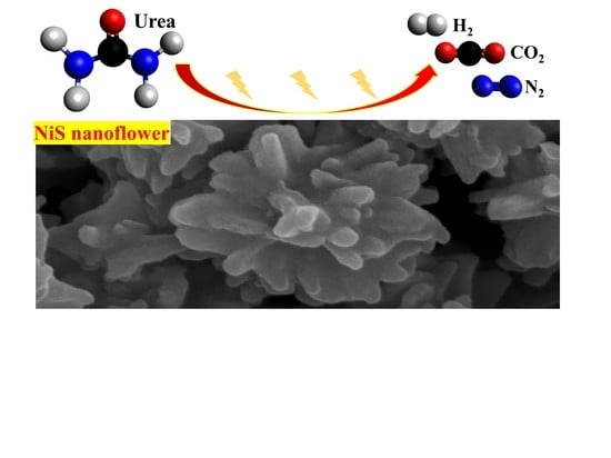
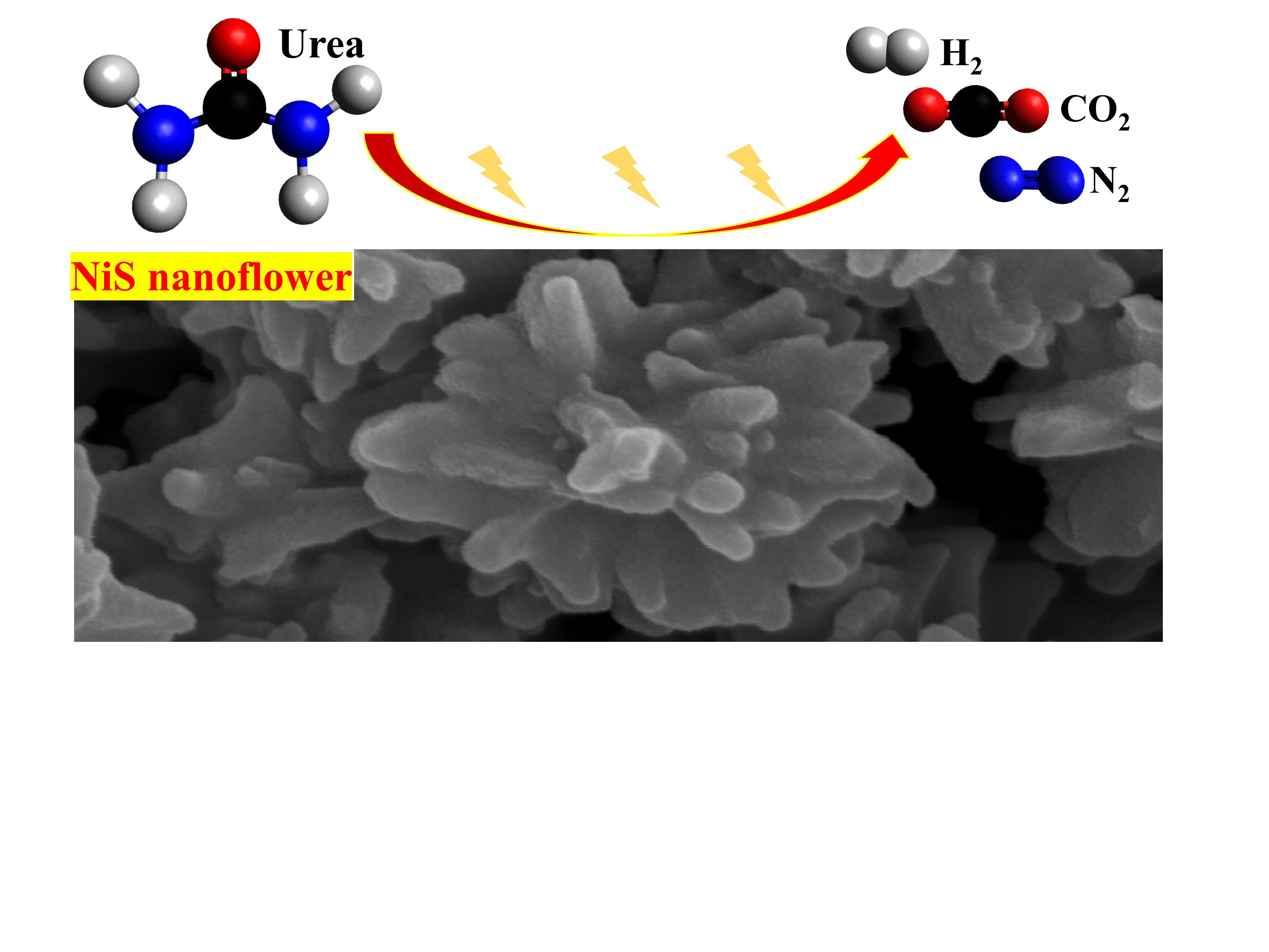
Nanostructured β−NiS Catalyst for Enhanced and Stable Electro−oxidation of Urea

Department of Chemical and Materials Engineering, National Yunlin University of Science and Technology, Yunlin 64002, Taiwan
*
Author to whom correspondence should be addressed.
Catalysts 2020, 10(11), 1280; https://doi.org/10.3390/catal10111280
Submission received: 14 October 2020 / Revised: 30 October 2020 / Accepted: 31 October 2020 / Published: 4 November 2020

Abstract

:
Urea oxidation reaction (UOR) has received a high level of recent interest since electrochemical oxidation of urea can remediate harmful nitrogen compounds in wastewater and accomplish hydrogen fuel production simultaneously. Thus, urea is considered to be potential hydrogen energy source that is inherently safe for fuel cell applications. However, the catalytic reaction suffers from slow kinetics due to six electron transfer in UOR. In this work, β phase NiS is successfully prepared through facile hydrothermal reaction, in which diethanolamine (DEA) was added as chelating agent leading to 3D nanoflower morphology. The crystal structure, surface morphology, and chemical bonding of the β−NiS were characterized by X–ray diffraction (XRD), scanning electron microscope (SEM), and X−ray photoelectron spectroscopy (XPS), respectively. The UOR performance of NiS was evaluated by means of linear sweep voltammetry (LSV), Tafel analysis, electrochemical impedance spectroscopy (EIS), chronoamperometry, and chronopotentiometry in 1 M KOH electrolyte containing 0.33 M urea. Compared to the Ni(OH)2 counterpart, NiS exhibits lower onset potential, increased current responses, faster kinetics of urea oxidation, lower charge transfer resistance, and higher urea diffusion coefficient, leading to the enhanced catalytic performance toward UOR. Moreover, the developed NiS catalyst exhibits superior stability and tolerance towards urea electro−oxidation in 10,000 s test.

Graphical Abstract

1. Introduction

Urea is considered a promising hydrogen storage carrier on account of its outstanding energy density (16.9 MJ L−1), which is even higher than that of compressed (5.6 MJ L−1) or liquid hydrogen (10.1 MJ L−1) [1]. In addition, urea has the merits of being inexpensive, non−toxic, non−flammable, and easy for storage and transportation [2], making urea a sustainable alternative to implement hydrogen economy and hence to supply energy. On the other hand, urea-containing wastewater from agriculture fertilizer and human/animal urine can go through a natural conversion turning into ammonia and nitrate, which could potentially cause eutrophication of rivers/lakes and contamination of drinking water [3]. It is challenging to tackle this issue due to high water solubility, non−flammability, and high stability of urea at room temperature and ambient pressure. Urea oxidation reaction (UOR) offers great promise to address this issue. Lan et al. [4] proposed the concept of direct urea fuel cell (DUFC), in which urea can be oxidized at the anode giving environment−friendly compounds (N2, H2O, and CO2), meanwhile hydrogen (H2) can be produced at the cathode [5]. The reactions can be expressed as following:
Anode: CO(NH2)2(aq) + 6OH(aq) → N2(g) + 5H2O(l) +CO2(g) + 6e
Cathode: 6H2O(l) + 6e → 3H2(g) + 6OH(aq)
Overall catalytic reaction: CO(NH2)2(aq) + H2O(l) → N2(g) + 3H2(g) +CO2(g)
It is worth mentioning that urea is oxidized at a standard electrode potential of −0.46 V (vs. SHE), whereas water is reduced on the cathode at −0.83 V (vs. SHE) in alkaline electrolytes. Accordingly, the cell potential of the overall catalytic reaction is only 0.37 V, which is significantly less than the 1.23 V required to produce hydrogen by water electrolysis. As such, UOR can generate hydrogen fuel and concurrently remedy urea-containing wastewater before urea naturally hydrolyzes in the environment. Thus, UOR receives high level of recent interest.
Although urea is considered to be a potential hydrogen source, slow kinetics due to six electron transfer in UOR has been a major restriction. This greatly limits the power performance of DUFCs at room temperature [6]. Therefore, developing efficient electrocatalysts to promote the reaction rate is the major focus in this field. The catalytic performance of Ag [7], Ru−TiO2 [8], Ti/Pt [9], Pt−Ir [10], IrO2 [11], and Ta2O5−IrO2 [12] have been investigated. However, the scarcity and high cost of these catalysts limits their practical application on a large scale. Recently, Boggs et al. [5] discovered the efficacy of inexpensive Ni−based catalysts in UOR, since Ni−based catalysts exhibit the lowest onset potential in alkaline medium (5 M KOH containing 0.33 M urea) compared with Pt, Pt−Ir, and Rh catalysts. Moreover, H2 gas production was also verified by gas chromatography, which proves hydrogen evolution reaction (HER). Since then, Ni−based catalysts have been extensively studied as the catalysts for UOR. For instance, the electrocatalytic performance of Ni(OH)2 with various morphologies, such as Ni(OH)2 nanoparticle [13], Ni(OH)2 nanotube [14], Ni(OH)2 nanocube [15], and NiO nanosheet [16] have been investigated. Moreover, recent studies reveal that urea undergoes an electrochemical−chemical (EC) mechanism [17,18,19]:
Electrochemical reaction: 6Ni(OH)2(s) + 6OH(aq) → 6NiOOH(s) +6H2O(l) + 6e
Chemical reaction: 6NiOOH(s) + CO(NH2)2(aq) + H2O(l) → 6Ni(OH)2(s) +N2(g) + CO2(g)
In the first step, the Ni2+ sites are electrochemically oxidized to Ni3+ in alkaline electrolyte. Then, urea is chemically decomposed by active Ni3+ forming CO2 and N2, while Ni2+ sites are regenerated simultaneously [17]. Accordingly, the reversibility of Ni2+/Ni3+ redox conversion and overall electrical conductivity of the electrocatalysts are crucial factors in UOR.
Recently, nickel sulfides [20,21,22], selenides [23,24], phosphides [25,26], and nitrides [27] have been investigated as HER electrocatalysts. Noticeably, sulfur incorporation endows metallic properties due to the presence of a continuous network of Ni−Ni bonds throughout the structure [28]. Thus, the overall electrical conductivity of the catalysts can be improved, enabling promising electrocatalytic performance toward HER. However, only a few studies utilized nickel sulfides as UOR electrocatalysts. Zhu et al. [29] discovered sulfur−treated Ni(OH)2 delivers a much higher current density (ca. 35 mA cm−2) in comparison with Ni(OH)2 counterpart (ca. 2.5 mA cm−2). The enhanced UOR catalytic activity is ascribed to the high conductivity of the catalyst (3.19 × 10³ S m−1 at room temperature). Liu et al. [30] synthesized Ni3S2 nanowires via hydrothermal sulfurization of a nickel foam. The obtained electrode exhibits enhanced UOR performance with the stable catalytic performance over 8 h in the electrolyte containing 1 M NaOH and 0.33 M urea. Nonetheless, a remarkable diversity of nickel chalcogenide can be obtained, such as NiS, Ni3S4, and NiS2. However, the UOR performance of these materials has not yet been revealed.
Herein, we successfully synthesized nanoflower β−NiS catalysts by facile hydrothermal method with DEA as the coordination agent and solvent. The obtained β−NiS serves as a highly efficient UOR electrocatalysts with onset potential of 1.40 V (vs. RHE) and Tafel slope of 66 mV dec−1, which is superior to Ni(OH)2 counterpart (onset potential: 1.45 V, Tafel slope: 162 mV dec−1). The unique flower-like morphology of β−NiS provides abundant active sites exposed to urea electrolyte. Moreover, high electrical conductivity of β−NiS renders good electron transport pathways in the electrode. Thus, the enhanced UOR performance of nanoflower β−NiS is achieved.

2. Results and Discussion

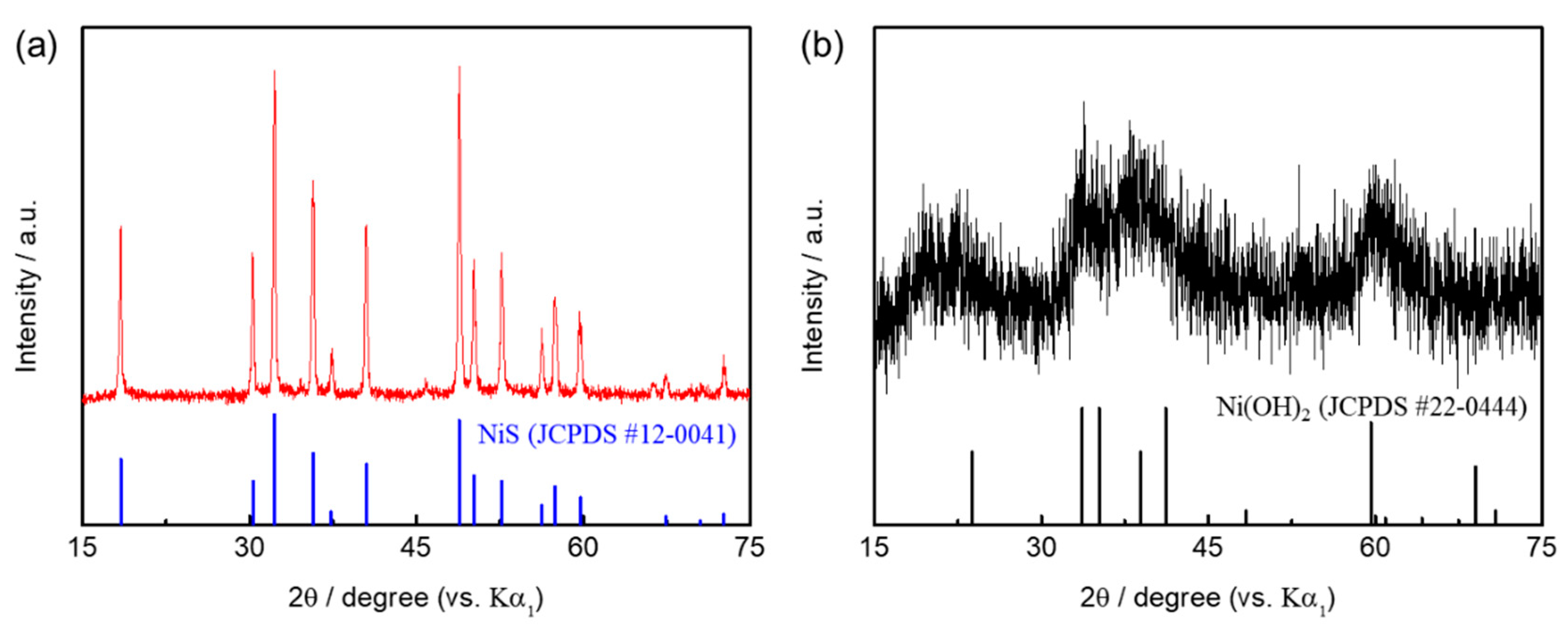
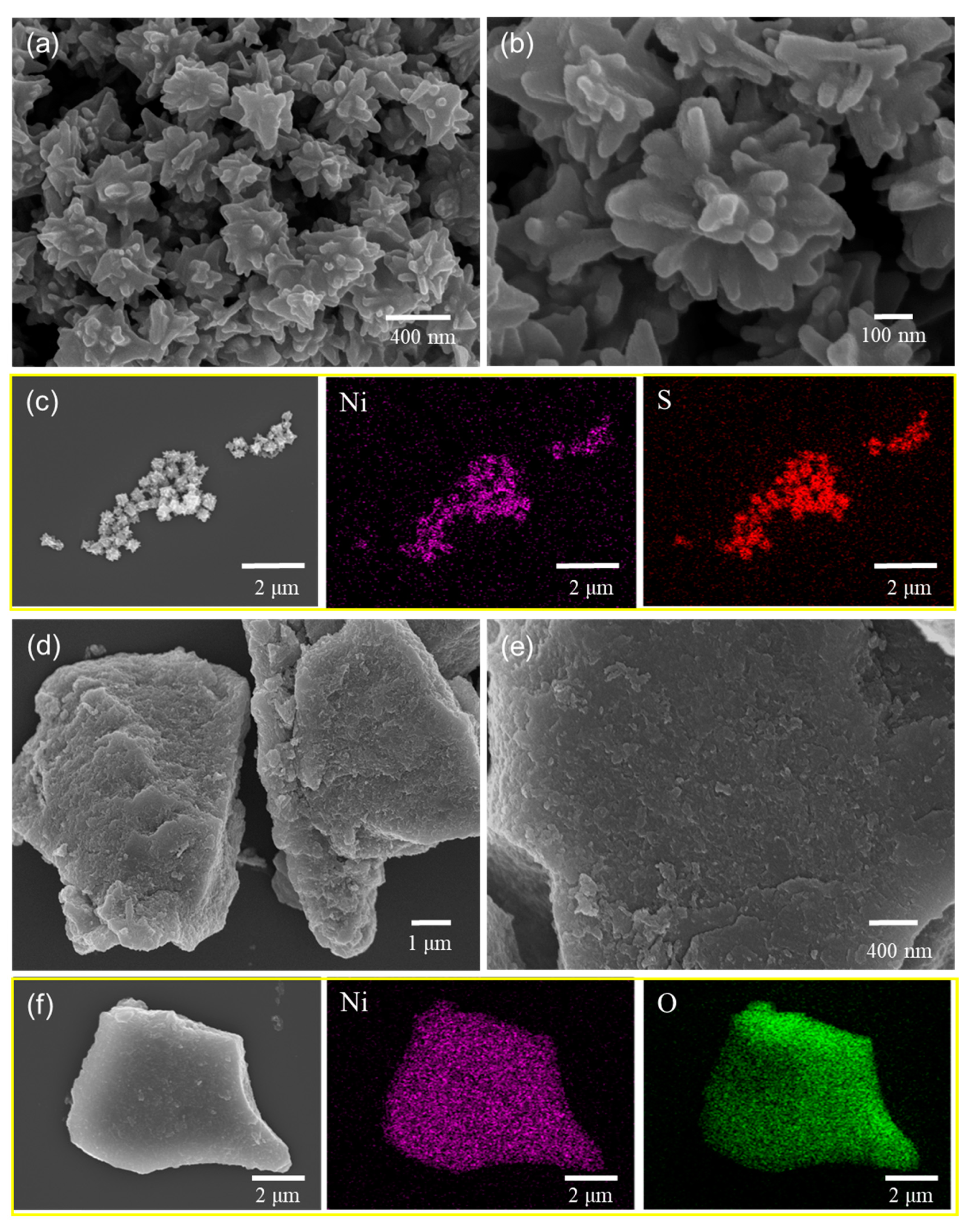
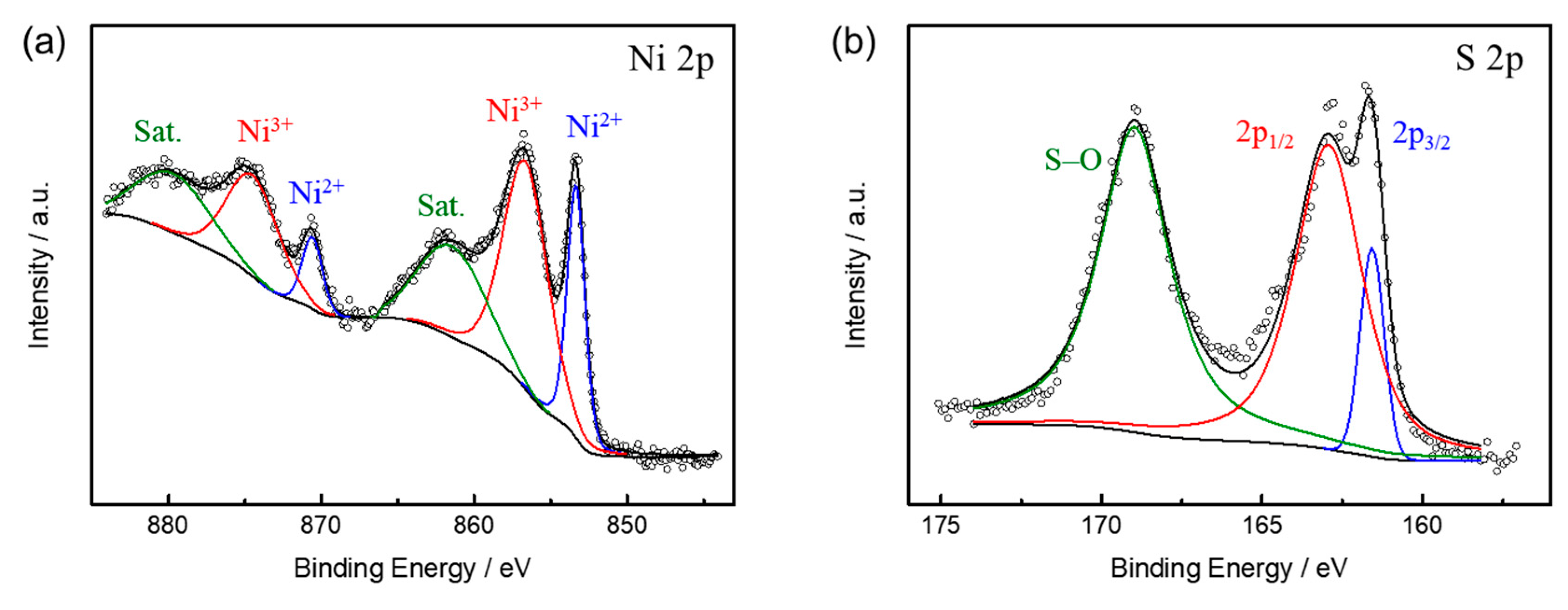
2.1. Characterizations of Materials

The reaction mechanism of β−NiS involves nucleation and crystallization of primary particles whose morphology can be manipulated by adding chelating agents [31]. In this work, nanoflower β−NiS was prepared by facile hydrothermal method using NiCl2, thiourea, and DEA as reactants. Thiourea is the sulfur source that can be decomposed under elevated temperature releasing H2S. DEA serves as chelating agent forming a complex with the NiCl2, which further reacts with H2S to form the NiS nucleus. Then, the growth of β−NiS is attributed to an Ostwald ripening process, leading to nanoflower morphology. The XRD pattern of pristine NiS is shown in Figure 1a, where all peaks can be indexed to the rhombohedral structure with an R3m space group. The main characteristic peaks at 18.4°, 30.3°, 32.2°, 35.7°, 40.5°, and 48.8° match well with the (110), (101), (300), (021), (211), and (131) planes of β−NiS (JCPDS No. 12−0041), respectively. The sharp diffraction peaks indicate the high crystallinity of as-prepared NiS. Figure 1b shows the XRD pattern of Ni(OH)2, which can be correlated with the pattern of α−Ni(OH)2 (JCPDS No. 22−0444). In particular, the turbo-stratified structure with 2θ between 30° and 45° can be identified. The broad peaks in the XRD pattern of Ni(OH)2 reveal a rather poorly crystalline α−phase, which are in good agreement with previous work [32]. The surface morphology of β−NiS was characterized by SEM, revealing a uniform dispersed flower-like nanostructure with an average size of 300−500 nm that has rounded circular center with multiple spine stretching out (Figure 2a,b). Elemental mapping exhibits the uniform distribution of Ni and S in the sample (Figure 2c), and EDS spectrum further confirms the atomic ratio of Ni and S corresponding to the formula of NiS. On the other hand, Ni(OH)2 demonstrates bulky chunks with the size of 5−10 μm (Figure 2d−f). Rational design nanostructures of electrocatalysts is an effective method to improve the electrochemical utilization of active materials and hence boost the catalytic performance. Therefore, the nanoflower architecture of the obtained NiS is anticipated to enhance the UOR performance.
To gain information on the chemical states of NiS, XPS measurements were carried out and the high-resolution Ni 2p and S 2p spectra were fitted by the Gaussian method. As shown in Figure 3a, the Ni 2p spectrum can be fitted with two spin-orbit doublets and two shark-up satellites (marked as ‘Sat.’). The binding energy at 853.4 eV in Ni 2p 3/2 and 870.6 eV in Ni 2p 1/2 correspond to the Ni2+, while the binding energy at 856.2 eV in Ni 2p 3/2 and 874.0 eV in Ni 2p 1/2 are the characteristic of Ni3+ [33]. For the S 2p spectrum of NiS (Figure 3b), the binging energy at 161.8 and 162.6 eV correspond to S 2p 3/2 and S 2p 1/2, respectively, indicating that the S element exists as sulfur anion in the NiS lattice [34]. Meanwhile, the peak at 168.6 eV is assigned to surface S−O bonds [35], which may originate from the partial surface oxidation while the sample is exposed to air. Based on the XPS results, the coexistence of Ni2+ and Ni3+ indicates that the exposed Ni sites on the surface of NiS catalyst are in a highly active state, which can offer rich redox reactions and hence lead to the enhanced electrochemical performance.

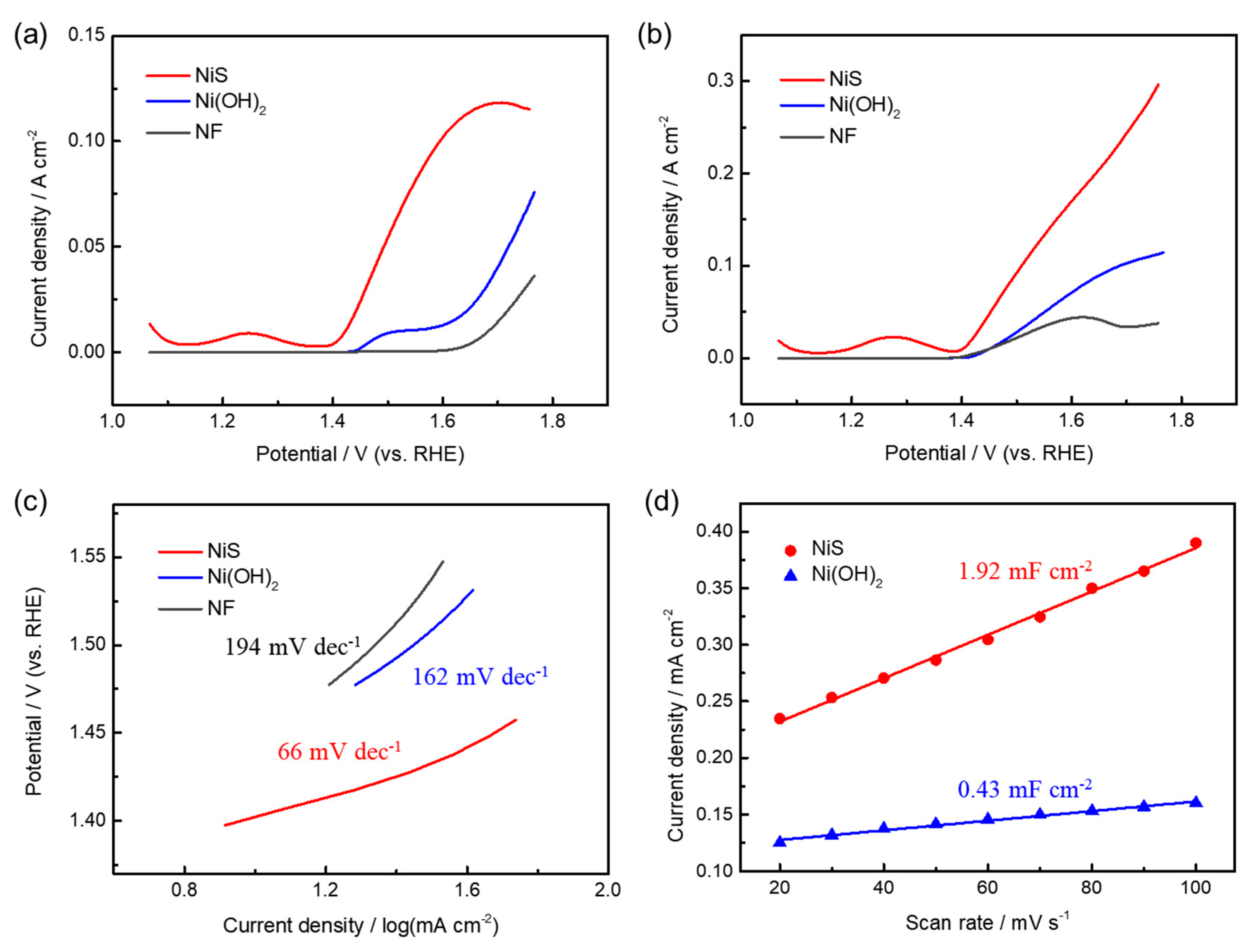
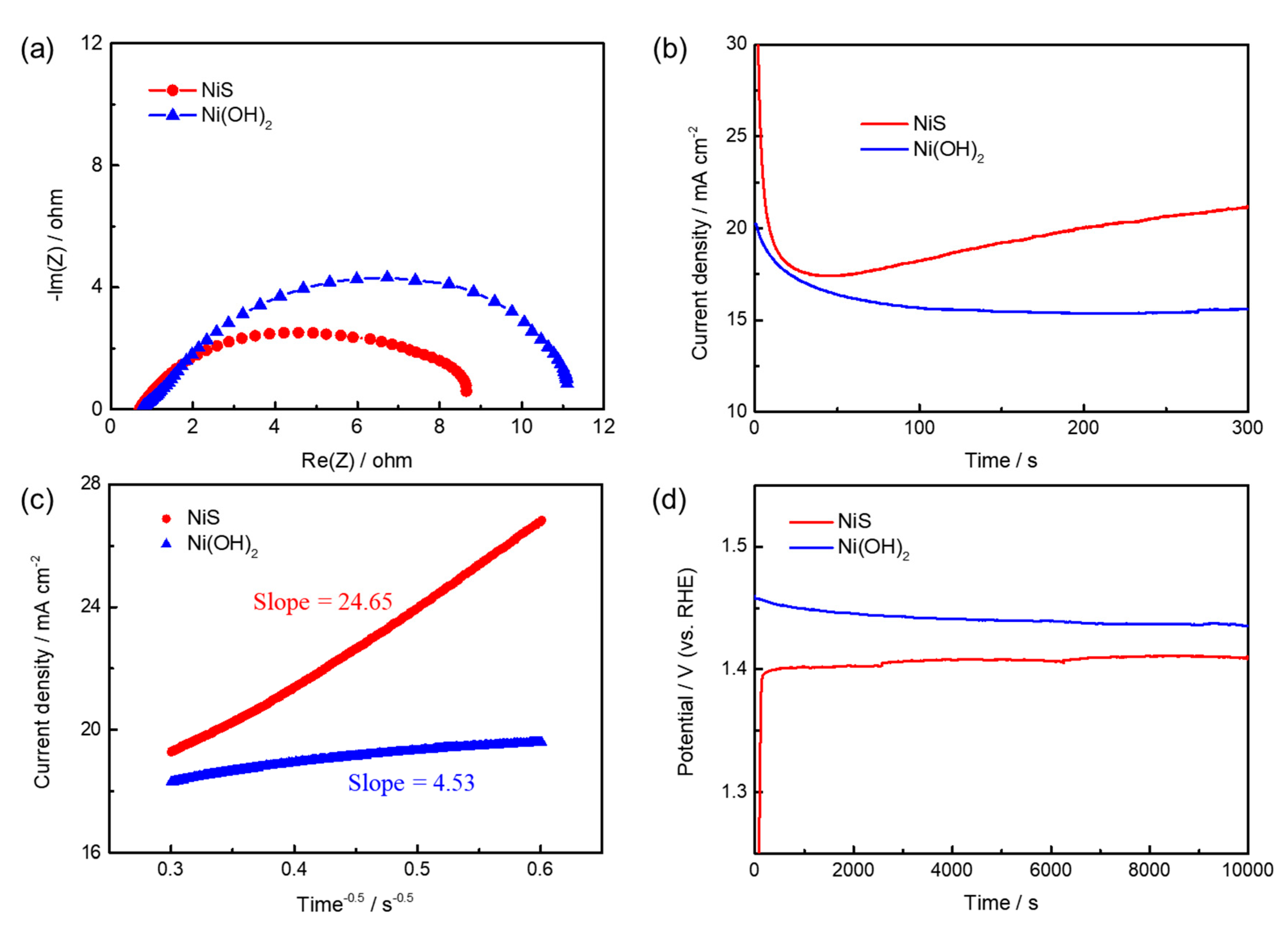
2.2. Electrochemical Oxidation of Urea

The electrochemical performance of NiS was firstly investigated in 1 M KOH using (LSV) at a scan rate of 5 mV s−1 with a three-electrode configuration as shown in Figure 4a. The oxidation peak located at ca. 1.27 V can be observed, which is attributed to the partial sulfur dissolution that has been commonly observed in cobalt and iron sulfides in aqueous alkaline medium [36,37]. The current responses above ca. 1.40 V correspond to the oxidation of Ni2+ to Ni3+. The overall reactions can be expressed as following [31,38]:
NiS + H2O + 1/2 O2→ Ni(OH)2 + S
NiS + OH → NiSOH + e
Ni(OH)2 + OH → NiOOH + H2O + e
On the other hand, the oxidation of Ni(OH)2 to NiOOH takes place at a relatively higher potential, i.e., 1.45 V. The increased current density at the potential higher than 1.60 V is ascribed to the occurring of oxygen evolution reaction. It is worth mentioning that Ni3+ centers are known as active sites for electro−oxidation of urea [17]. Allowing the oxidation of Ni2+ to Ni3+ at lower overpotentials is beneficial to UOR application. From this viewpoint, NiS is anticipated to exhibit superior catalytic activity toward UOR intrinsically. The UOR performance of NiS was then evaluated in 1 M KOH with the presence of 0.33 M urea. The onset potential of electrocatalyst is determined by the potential at which the current density reaches 10 mA cm−2 on the LSV curve. From Figure 4b, the onset potential of NiS is 1.40 V, which outperforms the Ni(OH)2 counterpart (1.45 V), LaNiO3 (1.43 V) [39], NiCo2O4 (1.63 V) [40], and NiMoO4 (1.62 V) [41]. Moreover, the current density reaches 50 mA cm−2 at 1.45 V for NiS electrode, while it requires 1.55 V for the Ni(OH)2 electrode to attain the same oxidative current density. It is worth mentioning that the catalytic responses of the Ni foam (NF) are significantly lower than NiS and Ni(OH)2, indicating the current collector has negligible contribution to the UOR. The smaller onset potential and the significant increase in current responses indicate that the obtained nanoflower NiS exhibits enhanced activity for UOR.
The Tafel slope is an indicator to evaluate the kinetics of electrochemical reactions. Figure 4c shows the Tafel plots obtained from the LSV curves at a scan rate of 5 mV s−1 in 1 M KOH with the presence of 0.33 M urea. The Tafel slope of NiS and Ni(OH)2 is 66 and 162 mV dec−1, respectively. The smaller Tafel slope indicates the faster kinetics of urea oxidation on the NiS electrocatalyst. Besides, the electrochemical double−layer capacitance measurements were conducted to evaluate the electrochemical active surface area (ECSA) of the electrocatalysts. As shown in Figure 4d, the double-layer capacitance can be determined by the slope in the current−scan rate curve, which was extracted from the cyclic voltammetry (CV) curves at the scan rate of 20−100 mV s−1 in the potential window between 0.87 and 1.07 V. The double-layer capacitance of NiS is calculated as 1.92 mF cm−2, which is ca. 4.5 times higher than that of Ni(OH)2 (0.43 mF cm−2), suggesting abundant electrochemical active sites of NiS exposed to the electrolyte.
EIS was used to study the charge transfer kinetics of NiS and Ni(OH)2 catalysts. The Nyquist plots (Figure 5a) were measured at the corresponding onset potentials of NiS and Ni(OH)2 catalysts with an amplitude of 10 mV in the frequency between 0.1 Hz and 100 kHz. The smaller diameter of the semi−circle means the lower charge transfer resistance in NiS, which is attributed to higher electrical conductivity of transition metal chalcogenide [34]. The improved electron transport in NiS renders facile redox transition between Ni2+ and Ni3+, which is crucial for oxidizing urea and regeneration of Ni2+ sites. Moreover, the chronoamperometry plot (i−t plot) of NiS measured at 1.42 V in 1 M KOH containing 0.33 M urea is shown in Figure 5b. The diffusion coefficient of urea (D) can be calculated based on the equation:
i = (n F D0.5 Cb)/(π0.5 t0.5)
where i is the current responses (mA cm−2); n is number of electrons involved in the oxidation of urea; F is the Faraday constant (C mol−1); Cb is the molar concentration of urea (mol cm−3); t is time (s). From the slope of the current density vs. t−0.5 plot (Figure 5c), the diffusion coefficient of urea in NiS is estimated to be 5.23 × 10⁻⁸ cm2 s−1, which is ca. 30 times higher than that of Ni(OH)2 (1.77 × 10⁻⁹ cm2 s−1). The results indicate the facile transport of urea in NiS catalyst, which is in line with the higher current responses observed from the LSVs (Figure 4b). Furthermore, a chronopotentiometric test was conducted to evaluate the catalytic stability under a constant current density of 10 mA cm−2. From Figure 5d, the NiS demonstrates excellent catalytic stability without noticeable changes in overpotential during 10,000 s test, revealing excellent durability of NiS electrocatalyst toward UOR. The relatively higher potential of Ni(OH)2 is in good agreement with the LSV measurements, where the onset potential of Ni(OH)2 is slightly higher than that of NiS.
Based on the above analyses, the rational design of β−NiS is achieved by adding proper amount of DEA chelating agent, leading to nanoflower morphology that allows abundant electrochemical active sites of NiS exposed to urea in the electrolyte. The nanoflower NiS demonstrates lower onset potential, increased current responses, faster kinetics of urea oxidation, lower charge transfer resistance, and higher urea diffusion coefficient. As a result, nanoflower β−NiS is a highly efficient UOR electrocatalysts.

3. Experimental

3.1. Preparation of Materials

All the chemicals used in this work were of analytical grade and used without further purification. The β−NiS was prepared by facile hydrothermal method. An amount of 3.33 mmol NiCl2 (98%, Sigma−Aldrich, St. Louis, MO, USA) was dissolved in an 80 mL mixture solvent composed of diethanolamine (DEA) and distilled water (1:3 volumetric ratio). Then, 13.32 mmol thiourea (99%, Sigma−Aldrich) was added into the above solution under vigorous stir for 15 min. Afterward, the mixture was transferred to a Teflon lined steel autoclave with the capacity of 100 mL and maintained at 180 °C for 12 h. After natural cooling, the product was obtained by centrifugation several times with DI–water and ethanol. The collected precipitates were dried in 80 °C oven overnight. Ni(OH)2 was synthesized by precipitation method. The nickel hydroxide slurry was obtained by mixing 40 mL of 0.8 M NaOH (97%, Sigma−Aldrich) and 160 mL of 0.3 M NiSO4 (98%, Sigma−Aldrich) under vigorous stir for 30 min. The slurry was washed repeatedly with distilled water, followed by overnight drying in 80 °C oven.

3.2. Characterizations

The crystal structures of catalysts were characterized by XRD (Rigaku MiniFlex II, Tokyo, Japan) using a Cu Kα source (λ = 1.54 Å). The surface morphologies of electrodes were examined by SEM (JEOL JSM−7610F Plus at 10 kV, Tokyo, Japan). The element mapping images were also examined by energy-dispersive X-ray spectroscopy (EDS). The surface chemical states of the catalysts were determined using a K-Alpha XPS (Thermo Fisher Scientific, Waltham, MA, USA) with an Al Kα radiation.

3.3. Electrochemical Measurements

All electrochemical measurements were carried out in a standard three-electrode configuration on an electrochemical workstation (CH Instruments, CHI 6273D, Austin, TX, USA). The active material (70%) was mixed with Super P carbon (20%) and poly(vinylidene difluoride) binder (10%) in N−methyl−2−pyrrolidone (NMP) solvent to form a slurry. The working electrodes were prepared by casting the slurry onto Ni foam (NF) with the typical mass loading of ca. 3.5 mg cm−2. Hg/HgO (1 M NaOH) and Pt wire were used as reference and counter electrodes, respectively. All the potentials in electrochemical data reported in this work are converted to reversible hydrogen electrode (RHE). LSV was tested at 5 mV s−1 to examine the onset potential of electrocatalysts, which was defined as the potential at which the current density reaches 10 mA cm−2 on the LSV curve. EIS was recorded at onset potential with an amplitude of 10 mV in the frequency between 0.1 Hz and 100 kHz. The potential window was set as 0.87 to 1.07 V for the electrochemically active surface area (ECSA) measurements. Chronopotentiometry was conducted to evaluate the catalytic stability under a constant current density of 10 mA cm−2.

4. Conclusions

This work reveals an advanced electrocatalyst, β−NiS, for urea oxidation. The NiS has good electron transport pathways due to high electrical conductivity in the sample. The morphology of NiS can be manipulated into nanoflower structure, allowing abundant electrochemical active sites of NiS exposed to urea electrolyte. The catalytic performance of NiS is evaluated by means of LSV, Tafel, ECSA, EIS, chronoamperometric, and chronopotentiometric tests. The results demonstrate that nanoflower NiS exhibits lower onset potential, increased current responses, faster kinetics of urea oxidation, lower charge transfer resistance, and higher urea diffusion coefficient. The enhanced UOR performance is further confirmed by long-term stability test, in which no noticeable changes in overpotential can be found, thus manifesting the importance of this work.

Author Contributions

T.-H.W. conceived and designed the experiments; Y.-C.L., B.-W.H., and W.-Y.L. carried out the experiments and analyzed the data; T.-H.W. wrote and finalize the manuscript. All authors have read and agreed to the published version of the manuscript.

Funding

This research was funded by Ministry of Science and Technology, Taiwan grant number MOST 109−2222−E−224−001−MY3.

Acknowledgments

The authors acknowledge the financial support from Ministry of Science and Technology, Taiwan, grant number MOST 109−2222−E−224−001−MY3.

Conflicts of Interest

The authors declare no conflict of interest.

References

  1. Mazloomi, K.; Gomes, C. Hydrogen as an energy carrier: Prospects and challenges. Renew. Sustain. Energy Rev. 2012, 16, 3024–3033. [Google Scholar] [CrossRef]
  2. Rollinson, A.N.; Jones, J.; Dupont, V.; Twigg, M.V. Urea as a hydrogen carrier: A perspective on its potential for safe, sustainable and long-term energy supply. Energy Environ. Sci. 2011, 4, 1216–1224. [Google Scholar] [CrossRef] [Green Version]
  3. Hamonts, K.; Balaine, N.; Moltchanova, E.; Beare, M.; Thomas, S.; Wakelin, S.A.; O’Callaghan, M.; Condron, L.M.; Clough, T.J. Influence of soil bulk density and matric potential on microbial dynamics, inorganic N transformations, N2O and N2 fluxes following urea deposition. Soil Biol. Biochem. 2013, 65, 1–11. [Google Scholar] [CrossRef]
  4. Lan, R.; Tao, S.; Irvine, J.T.S. A direct urea fuel cell—Power from fertiliser and waste. Energy Environ. Sci. 2010, 3, 438–441. [Google Scholar] [CrossRef] [Green Version]
  5. Boggs, B.K.; King, R.L.; Botte, G.G. Urea electrolysis: Direct hydrogen production from urine. Chem. Commun. 2009, 32, 4859–4861. [Google Scholar] [CrossRef] [PubMed]
  6. Xu, W.; Wu, Z.; Tao, S. Urea-Based Fuel Cells and Electrocatalysts for Urea Oxidation. Energy Technol. 2016, 4, 1329–1337. [Google Scholar] [CrossRef] [Green Version]
  7. Ahmad, R.; Tripathy, N.; Hahn, Y.-B. Highly stable urea sensor based on ZnO nanorods directly grown on Ag/glass electrodes. Sens. Actuators B Chem. 2014, 194, 290–295. [Google Scholar] [CrossRef]
  8. Simka, W.; Piotrowski, J.; Robak, A.; Nawrat, G. Electrochemical treatment of aqueous solutions containing urea. J. Appl. Electrochem. 2009, 39, 1137–1143. [Google Scholar] [CrossRef]
  9. Carlesi Jara, C.; Di Giulio, S.; Fino, D.; Spinelli, P. Combined direct and indirect electroxidation of urea containing water. J. Appl. Electrochem. 2008, 38, 915–922. [Google Scholar] [CrossRef]
  10. King, R.L.; Botte, G.G. Investigation of multi-metal catalysts for stable hydrogen production via urea electrolysis. J. Power Sources 2011, 196, 9579–9584. [Google Scholar] [CrossRef]
  11. Amstutz, V.; Katsaounis, A.; Kapalka, A.; Comninellis, C.; Udert, K.M. Effects of carbonate on the electrolytic removal of ammonia and urea from urine with thermally prepared IrO2 electrodes. J. Appl. Electrochem. 2012, 42, 787–795. [Google Scholar] [CrossRef]
  12. Simka, W.; Piotrowski, J.; Nawrat, G. Influence of anode material on electrochemical decomposition of urea. Electrochim. Acta 2007, 52, 5696–5703. [Google Scholar] [CrossRef]
  13. Xia, L.; Liao, Y.; Qing, Y.; Xu, H.; Gao, Z.; Li, W.; Wu, Y. In Situ Growth of Porous Ultrathin Ni(OH)2 Nanostructures on Nickel Foam: An Efficient and Durable Catalysts for Urea Electrolysis. ACS Appl. Energy Mater. 2020, 3, 2996–3004. [Google Scholar] [CrossRef]
  14. Ji, R.-Y.; Chan, D.-S.; Jow, J.-J.; Wu, M.-S. Formation of open-ended nickel hydroxide nanotubes on three-dimensional nickel framework for enhanced urea electrolysis. Electrochem. Commun. 2013, 29, 21–24. [Google Scholar] [CrossRef]
  15. Wu, M.-S.; Ji, R.-Y.; Zheng, Y.-R. Nickel hydroxide electrode with a monolayer of nanocup arrays as an effective electrocatalyst for enhanced electrolysis of urea. Electrochim. Acta 2014, 144, 194–199. [Google Scholar] [CrossRef]
  16. Wu, M.-S.; Lin, G.-W.; Yang, R.-S. Hydrothermal growth of vertically-aligned ordered mesoporous nickel oxide nanosheets on three-dimensional nickel framework for electrocatalytic oxidation of urea in alkaline medium. J. Power Sources 2014, 272, 711–718. [Google Scholar] [CrossRef]
  17. Vedharathinam, V.; Botte, G.G. Direct evidence of the mechanism for the electro-oxidation of urea on Ni(OH)2 catalyst in alkaline medium. Electrochim. Acta 2013, 108, 660–665. [Google Scholar] [CrossRef]
  18. Vedharathinam, V.; Botte, G.G. Understanding the electro-catalytic oxidation mechanism of urea on nickel electrodes in alkaline medium. Electrochim. Acta 2012, 81, 292–300. [Google Scholar] [CrossRef]
  19. Wang, D.; Botte, G.G. In Situ X-Ray Diffraction Study of Urea Electrolysis on Nickel Catalysts. ECS Electrochem. Lett. 2014, 3, H29–H32. [Google Scholar] [CrossRef]
  20. Ouyang, C.; Wang, X.; Wang, C.; Zhang, X.; Wu, J.; Ma, Z.; Dou, S.; Wang, S. Hierarchically Porous Ni3S2 Nanorod Array Foam as Highly Efficient Electrocatalyst for Hydrogen Evolution Reaction and Oxygen Evolution Reaction. Electrochim. Acta 2015, 174, 297–301. [Google Scholar] [CrossRef]
  21. Jiang, N.; Tang, Q.; Sheng, M.; You, B.; Jiang, D.-E.; Sun, Y. Nickel sulfides for electrocatalytic hydrogen evolution under alkaline conditions: A case study of crystalline NiS, NiS2, and Ni3S2 nanoparticles. Catal. Sci. Technol. 2016, 6, 1077–1084. [Google Scholar] [CrossRef]
  22. Sivanantham, A.; Ganesan, P.; Shanmugam, S. Hierarchical NiCo2S4 Nanowire Arrays Supported on Ni Foam: An Efficient and Durable Bifunctional Electrocatalyst for Oxygen and Hydrogen Evolution Reactions. Adv. Funct. Mater. 2016, 26, 4661–4672. [Google Scholar] [CrossRef]
  23. Tang, C.; Cheng, N.; Pu, Z.; Xing, W.; Sun, X. NiSe Nanowire Film Supported on Nickel Foam: An Efficient and Stable 3D Bifunctional Electrode for Full Water Splitting. Angew. Chem. Int. Ed. Engl. 2015, 54, 9351–9355. [Google Scholar] [CrossRef]
  24. Zhou, H.; Yu, F.; Liu, Y.; Sun, J.; Zhu, Z.; He, R.; Bao, J.; Goddard, W.A.; Chen, S.; Ren, Z. Outstanding hydrogen evolution reaction catalyzed by porous nickel diselenide electrocatalysts. Energy Environ. Sci. 2017, 10, 1487–1492. [Google Scholar] [CrossRef] [Green Version]
  25. You, B.; Jiang, N.; Sheng, M.; Bhushan, M.W.; Sun, Y. Hierarchically Porous Urchin-Like Ni2P Superstructures Supported on Nickel Foam as Efficient Bifunctional Electrocatalysts for Overall Water Splitting. ACS Catal. 2015, 6, 714–721. [Google Scholar] [CrossRef]
  26. Tang, C.; Zhang, R.; Lu, W.; Wang, Z.; Liu, D.; Hao, S.; Du, G.; Asiri, A.M.; Sun, X. Energy-Saving Electrolytic Hydrogen Generation: Ni2P Nanoarray as a High-Performance Non-Noble-Metal Electrocatalyst. Angew. Chem. Int. Ed. Engl. 2017, 56, 842–846. [Google Scholar] [CrossRef]
  27. Wang, F.; Zhao, D.; Zhang, L.; Fan, L.; Zhang, X.; Hu, S. Nanostructured Nickel Nitride with Reduced Graphene Oxide Composite Bifunctional Electrocatalysts for an Efficient Water-Urea Splitting. Nanomaterials 2019, 9, 1583. [Google Scholar] [CrossRef] [Green Version]
  28. Feng, L.L.; Yu, G.; Wu, Y.; Li, G.D.; Li, H.; Sun, Y.; Asefa, T.; Chen, W.; Zou, X. High-index faceted Ni3S2 nanosheet arrays as highly active and ultrastable electrocatalysts for water splitting. J. Am. Chem. Soc. 2015, 137, 14023–14026. [Google Scholar] [CrossRef]
  29. Zhu, X.; Dou, X.; Dai, J.; An, X.; Guo, Y.; Zhang, L.; Tao, S.; Zhao, J.; Chu, W.; Zeng, X.C.; et al. Metallic Nickel Hydroxide Nanosheets Give Superior Electrocatalytic Oxidation of Urea for Fuel Cells. Angew. Chem. Int. Ed. Engl. 2016, 55, 12465–12469. [Google Scholar] [CrossRef]
  30. Liu, M.; Jiao, Y.; Zhan, S.; Wang, H. Ni3S2 nanowires supported on Ni foam as efficient bifunctional electrocatalyst for urea-assisted electrolytic hydrogen production. Catal. Today 2020, 355, 596–601. [Google Scholar] [CrossRef]
  31. Yang, J.; Duan, X.; Qin, Q.; Zheng, W. Solvothermal synthesis of hierarchical flower-like β-NiS with excellent electrochemical performance for supercapacitors. J. Mater. Chem. A 2013, 1, 7880–7884. [Google Scholar] [CrossRef]
  32. Faure, C.; Delmas, C.; Fouassier, M. Characterization of a turbostratic α-nickel hydroxide quantitatively obtained from an NiSO4 solution. J. Power Sources 1991, 35, 279–290. [Google Scholar] [CrossRef]
  33. Chen, H.; Jiang, J.; Zhao, Y.; Zhang, L.; Guo, D.; Xia, D. One-pot synthesis of porous nickel cobalt sulphides: Tuning the composition for superior pseudocapacitance. J. Mater. Chem. A 2015, 3, 428–437. [Google Scholar] [CrossRef]
  34. Guan, B.; Li, Y.; Yin, B.; Liu, K.; Wang, D.; Zhang, H.; Cheng, C. Synthesis of hierarchical NiS microflowers for high performance asymmetric supercapacitor. Chem. Eng. J. 2017, 308, 1165–1173. [Google Scholar] [CrossRef]
  35. Jing, F.; Lv, Q.; Xiao, J.; Wang, Q.; Wang, S. Highly active and dual-function self-supported multiphase NiS–NiS2–Ni3S2/NF electrodes for overall water splitting. J. Mater. Chem. A 2018, 6, 14207–14214. [Google Scholar] [CrossRef]
  36. Yuan, C.; Gao, B.; Su, L.; Chen, L.; Zhang, X. Electrochemically Induced Phase Transformation and Charge-Storage Mechanism of Amorphous CoSx Nanoparticles Prepared by Interface-Hydrothermal Method.pdf. J. Electrochem. Soc. 2009, 156, A199–A203. [Google Scholar] [CrossRef]
  37. Tao, D.P.; Richardson, P.E.; Luttrell, G.H.; Yoon, R.H. Electrochemical studies of pyrite oxidation and reduction using freshly-fractured electrodes and rotating ring-disc electrodes. Electrochim. Acta 2003, 48, 3615–3623. [Google Scholar] [CrossRef]
  38. Li, W.; Wang, S.; Xin, L.; Wu, M.; Lou, X. Single-crystal β-NiS nanorod arrays with a hollow-structured Ni3S2 framework for supercapacitor applications. J. Mater. Chem. A 2016, 4, 7700–7709. [Google Scholar] [CrossRef]
  39. Forslund, R.P.; Mefford, J.T.; Hardin, W.G.; Alexander, C.T.; Johnston, K.P.; Stevenson, K.J. Nanostructured LaNiO3 Perovskite Electrocatalyst for Enhanced Urea Oxidation. ACS Catal. 2016, 6, 5044–5051. [Google Scholar] [CrossRef]
  40. Ding, R.; Qi, L.; Jia, M.; Wang, H. Facile synthesis of mesoporous spinel NiCo2O4 nanostructures as highly efficient electrocatalysts for urea electro-oxidation. Nanoscale 2014, 6, 1369–1376. [Google Scholar] [CrossRef]
  41. Tong, Y.; Chen, P.; Zhang, M.; Zhou, T.; Zhang, L.; Chu, W.; Wu, C.; Xie, Y. Oxygen Vacancies Confined in Nickel Molybdenum Oxide Porous Nanosheets for Promoted Electrocatalytic Urea Oxidation. ACS Catal. 2017, 8, 1–7. [Google Scholar] [CrossRef]
Figure 1. XRD patterns of (a) NiS and (b) Ni(OH)2.
Catalysts 10 01280 g001
Figure 2. SEM images of (a,b) NiS and (d,e) Ni(OH)2; elemental mapping images of (c) NiS and (f) Ni(OH)2.
Catalysts 10 01280 g002
Figure 3. High-resolution XPS (a) Ni 2p and (b) S 2p spectra of NiS.
Catalysts 10 01280 g003
Figure 4. LSV curves of NiS, Ni(OH)2, and Ni foam (NF) in (a) 1 M KOH and (b) 1 M KOH with 0.33 M urea at the scan rate of 5 mV s−1; (c) Tafel plot and (d) double−layer capacitance of NiS and Ni(OH)2 in 1 M KOH with 0.33 M urea.
Catalysts 10 01280 g004
Figure 5. (a) Nyquist plots of NiS and Ni(OH)2 measured at onset potential; (b) chronoamperometry plot of NiS and Ni(OH)2 measured at 1.42 V; (c) dependence of current on the time-0.5 derived from (b); (d) stability test of NiS measured at the current density of 10 mA cm−2 in 1 M KOH with 0.33 M urea.
Catalysts 10 01280 g005
Publisher’s Note: MDPI stays neutral with regard to jurisdictional claims in published maps and institutional affiliations.

