1. Introduction
Flexible thin film heaters (TFHs) are a type of plane heater that operates on a flexible substrate using Joule heating [
1,
2,
3]. For the better outdoors life of humans, the development of portable and flexible TFHs is important to maintain the body temperature of human more simply and efficiently. In particular, the potential and marketability of TFHs are very high, since high efficiency and portable heating elements are very important in the recent life pattern of human. Because the heat generated in TFH mainly occurs in current conducting materials, the design of high-quality current conducting materials could affect the performance of TFHs. To date, TFHs have been widely studied in the aerospace, defense, automobile, health, and wearable device industries [
4,
5,
6], because of their advantages of high efficiency, low resistance, flexibility, high response speed, and so forth. Typically, TFHs have been fabricated on conducting oxide or conducting carbon materials, due to their effective Joule heating at low power [
7,
8,
9,
10]. In the case of conducting oxide based TFHs, vacuum processed Sn-doped In
2O
3 and F-doped SnO
2 films have been used as heating materials. However, the high cost of physical vapor deposition for ITO and chemical vapor deposition for FTO and brittleness of conducting oxide remain as critical problems. Other types are conducting carbonaceous materials, such as carbon nanotubes and graphene-based TFHs, which are prepared by solution coating or transfer processes [
11,
12,
13,
14,
15]. To date, TFHs using carbon materials have been intensely studied since they have moderate electrical characteristics and a simple coating process. Among the conductive carbon materials, carbon fiber (CF) has excellent tensile strength, low density, high heat resistance, low thermal expansion coefficient, corrosion resistance, mechanical durability, good thermal conductivity and electrical conductivity [
16,
17,
18,
19,
20]. Furthermore, due to these virtues of the CF, it has been used as supporting platform and conductive media of photocatalysis [
21,
22,
23,
24], electrocatalysis [
25,
26,
27,
28,
29], and electrochemical energy storage [
30]. In particular, CF has great potential to be applied in fields with high growth potential such as oxygen evolution reactions and oxygen reduction reactions of battery anodes [
26,
27], and hydrogen evolution reactions by water splitting for the hydrogen economy [
23,
24,
25]. However, less attention has been paid with regards to its function as thermal management materials of catalysis. Moreover, CFs have suitable properties as heat management materials for flexible planar heating elements. This contrasts with the problems of cracking, uneven heat generation, heavyweight, low heating efficiency, and low mechanical flexibility of conventional heating elements (e.g., Ni–Cr and Fe–Cr alloys) [
8,
9,
10]. In particular, the high flexibility of CF makes it possible to apply it to various objects having curved surfaces and it is also suitable as wearable TFHs to be applied to clothes or human skin. In addition, CFTFHs are easy to manufacture, because of the atmospheric-based simple coating process. Due to these virtues, CF-based heaters have been studied as de-icing heaters, constant temperature heaters and thin film heaters [
31,
32,
33]. Although the potential of CF for TFHs is well known, research into the current flow direction effect on the performance of CFTFHs is still lacking. In this work, we investigated the current flow directing effect of CF-based flexible TFHs for application in wearable devices. The anisotropic alignment formed by roll-to-roll coating of CF layers results in anisotropic electrical properties, which are closely related to the performance of CFTFHs. The electrical and mechanical properties of CFs parallel and perpendicular to the roll-to-roll coating direction were investigated in detail. Furthermore, we compared the heating performance of anisotropic CFT FHs according to the alignment direction of CFs.
2. Results and Discussion
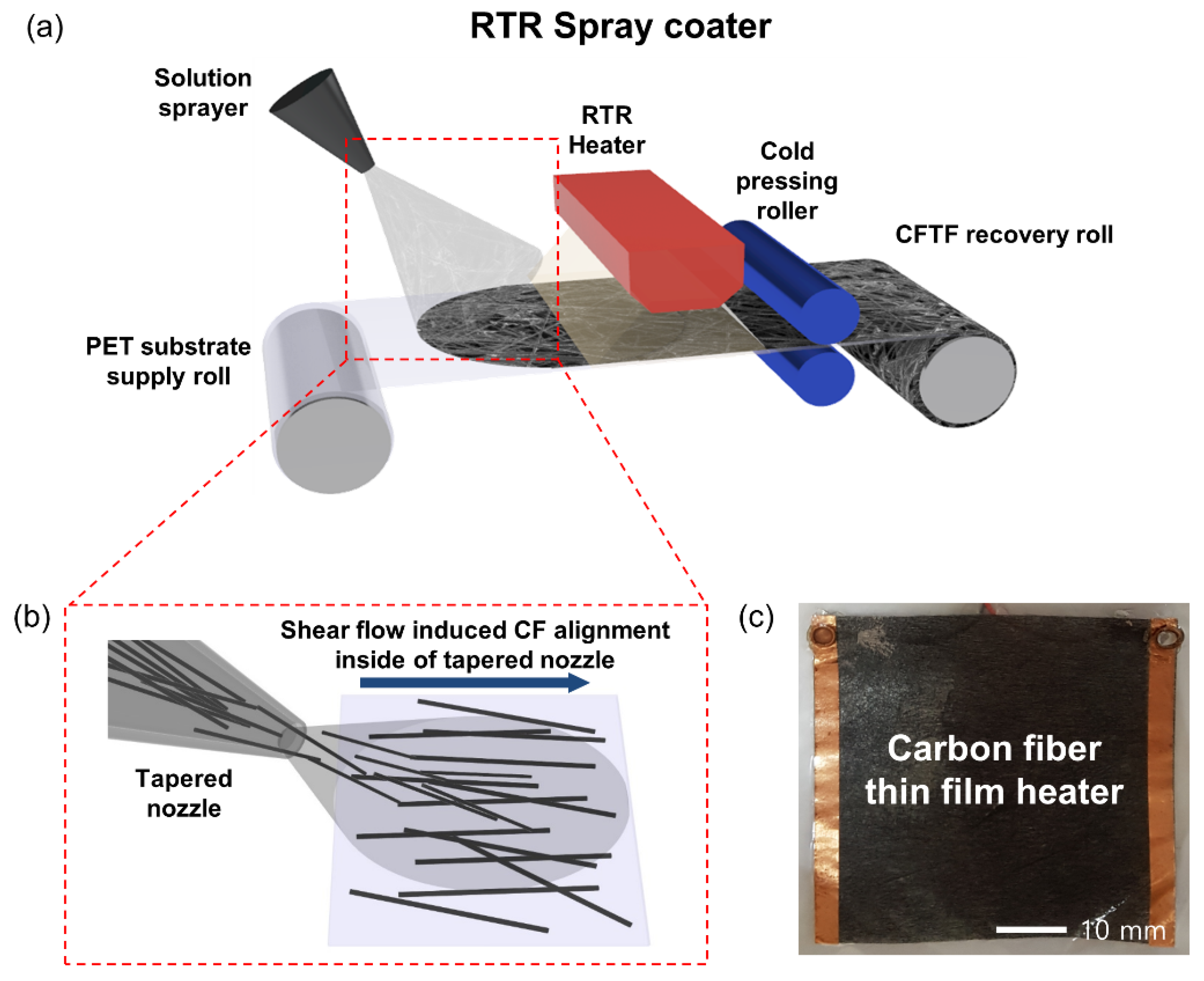
To coat CF films on a PET substrate, a typical roll-to-roll spray coater was employed. The thickness of CF films formed by using spray coating can be controlled by the distance between the substrate and the nozzle, the amount of sprayed solution, the speed of the roll-to-roll winder, and the diameter of the nozzle.
Figure 1a shows that roll-to-roll spray coating makes it easy to produce cost-efficient CF film at atmospheric condition. Therefore, this process is suitable for mass production. The CF solution was sprayed onto the surface of the moving PET from the supply and recovery roll. After spray coating of the CFs, the substrates were heated with hot air dryer to remove the solvent. Finally, Cu metal tape was attached to the edge of the CF-coated PET substrate to supply power. During the spray coating process, CFs accelerate in the direction of the highly viscous CF solution flow inside of the tapered nozzle, as CF solution is sprayed on the PET substrate through the nozzle [
34]. Therefore, due to the shear flow of CF solution, the long axes of the CFs are aligned along the flow direction of CF solution at the tapered nozzle and coated on PET substrate (
Figure 1b). The fiber alignment induced by flow has high levels of alignment with the potential for aligning more than 90% of fibers in the range (±15°) [
35].
Table 1 shows the electrical characteristics of the CFTFs that are measured by the four-point probe measurement according to the alignment of the CF. When the CF directions of CFTFs were parallel to the direction of the applied voltage for measuring (parallel CFTF), we observed the sheet resistance to be relatively low, compared to when the CF directions of CFTF’s were perpendicular to the direction of the applied voltage (perpendicular CFTF).
When the alignment direction of CFs was perpendicular to the direction of the applied voltage for measuring, the sheet resistance was measured to be 16.7 Ohm/square, and the sheet resistance in the parallel case was 9.6 Ohm/square. Moreover, the heat generated by the CFTFs is proportional to the square of the voltage and time, and inversely proportional to the resistance:
where,
is the generated heat,
, power; V, voltage;
, heating time; and
, resistance. So, we predicted that parallel CFTFs emit a larger amount of heat compared with perpendicular CFTFs under the same voltage, considering that the sheet resistance of parallel CFTFs are smaller than that of perpendicular CFTFs. Furthermore,
Table 1 also shows that we measured the sheet resistance and mobility of parallel CFTFs and perpendicular CFTFs by Hall measurement. The sheet resistance was measured to be 7.78 Ohm/square, and the mobility was measured to be 0.268 cm
2/Vs when the arrangement direction of CFs was perpendicular to the direction in which the voltage was applied. In the parallel case, the sheet resistance was 8.07 Ohm/square, and the mobility was 0.652 cm
2/Vs. In these measurements, the results of the Hall measurement show a different tendency from those obtained by the four-point probe measurement. In the Hall measurement result, unlike the four-point probe measurement, the sheet resistance of parallel CFTFs and perpendicular CFTFs are similar. This is because the sheet resistance measurement method of the Hall measurement equipment is the Van der Pauw method, which assumes that the measurement sample is an isotropic, homogeneous, and continuous thin film. Therefore, the sheet resistance of parallel CFTFs and perpendicular CFTFs are measured to a similar value, regardless of the directional relationship of CF direction and measuring direction of the voltage, even though anisotropic and discontinuous CFTFs have different sheet resistance depending on the measurement direction. Therefore, it is reasonable that we choose the sheet resistance value of the four-point probe measurement that shows the sheet resistance difference of parallel CFTFs and perpendicular CFTFs, and ignore the sheet resistance value obtained by Hall measurement. In the four-point probe measurement, the sheet resistance difference when the alignment direction of the CFs is parallel to the measuring direction is about 1.7 times smaller than the perpendicular case.
This result can be substantiated in
Figure 2a, which is the FESEM result of the CFTF. In this figure, when the angle formed by the imaginary perpendicular line is less than 45°, the conductive paths formed by CFs are colored blue; and when the line is more than 45°, the conductive paths formed by CF are colored red. Red conductive paths are relatively many in number compared to the blue conductive paths, which causes the parallel arranged conductive paths to connect together directly, and to create long percolation conductive paths in parallel and flow current in parallel (
Figure 2b, right). But the number of conductive paths arranged perpendicular is relatively small, compared with the parallel CF. Therefore, it is rare that perpendicular aligned CFs are directly connected to each other. Instead, they are indirectly connected by parallel arranged conductive path, as shown in
Figure 2b, left. This is the reason why the CFTF made by RTR spray coating has anisotropic electrical properties. So, the CFTFs show anisotropic properties due to the anisotropic percolation network caused by the various alignments of conducting fibers [
15,
36]. It was proven multiple times that the formation of anisotropic percolation networks depends on the concentration, aspect ratio, and degree of alignment of the added substance [
37,
38,
39]. Therefore, the anisotropic percolation network of CFTF is produced because of the high levels of CF alignment induced by the shear flow inside the CF spray tapered nozzle [
34], and the high aspect-ratio and high concentration of CFs that we use. Furthermore, Hall measurements were made of both the parallel and perpendicular CFTFs under the same electric field intensity due to the same voltage and the same size of both CFTFs. Mobility is the value of electron drift velocity multiplied by the distance between electrodes divided by the applied voltage between electrodes. Consequently, the apparent mobility of electron is proportional to the apparent drift velocity of electron in given geometry:
where,
is the apparent mobility in given geometry;
E, electric field intensity;
V, voltage;
d, distance between electrodes; and
, apparent drift velocity of electron in given geometry. As shown in
Table 1 and
Figure 2, the anisotropic percolation network of CFTF has CFs alignment induced by the RTR spray coating, so the apparent drift velocity of electron is larger when electrons flow in the direction parallel to the major arrangement of the CF, such as parallel CFTF (
Figure 2b, right). In contrast, when the electrons flow perpendicular to the major arrangement of the CFs, such as in the perpendicular CFTF (
Figure 2b, left), the apparent drift velocity of electron is smaller, because of the longer electron pathways according to orientation of CFs. The conduction pathways in perpendicular CFTF have a small number of parallel CFs, and are connected indirectly by perpendicular CFs. So, in the perpendicular CFTF, the electron pathways are relatively longer than in the parallel CFTF. Furthermore, the perpendicular CFs have lower electron drift velocity compared to the parallel CFs, due to the lower electric field intensity, because it is almost perpendicular to the direction of the applied voltage. Consequently, the conductive path of the perpendicular CFTF is a summation of the parallel CF and perpendicular CF, and the apparent drift velocity of electron is slower than that of the parallel CFTF, in which the conductive path consists of only parallel CFs. That is why the apparent mobility of the perpendicular CFTF is lower than that of the parallel CFTF.
We investigated how well the CFTF maintains its electrical properties by using bending radius test equipment.
Figure 3a shows the resistance changes in accordance with the bending radius of the perpendicular and parallel CFTFs during outer and inner substrate bending. In this measurement, the resistance change (ΔR) of the measured samples is expressed as (R-R0), where R0 is the initially measured resistance, and R is the resistance measured after bending of the sample. Perpendicular CFTF bending is the case of bending direction in which the direction of film movement backwards and forwards is perpendicular to the CF alignment, while parallel CFTF bending is the case in which the bending direction is parallel to the CF alignment. In the graph on the right side of
Figure 3a, constant resistance was observed until the bending radius was decreased to 3 mm in the inner bending test of both the perpendicular and parallel CFTFs; when the inner bending radius is 2 mm the resistance change increases slightly. The left side of
Figure 3a demonstrates the outer bending of both perpendicular and parallel CFTFs have constant resistance until the radius is 2 mm. Because of the thickness of the substrate of CFTF, we are not able to test under 1 mm radius; however, these tests show that the CFTFs are flexible thin film, due to the high strain resistance of the CFs, and which maintains its electrical characteristics, even if it bends in a small radius. Furthermore, when we consider that outer bending usually has higher critical bending radius compared to inner bending, due to the disconnection of conductive materials or delamination of conductive materials being easier, unlike these bending test results, we can derive that the resistance change caused by further inner bending radius decrease to less than 3 mm is due to the contact of the CFs together in that small inner bending radius. When the outer bending radius is decreased, the disconnection of CFs or delamination of CFs from the substrate does not happen well. The peak strains for flexible CFTFs with decreasing bending radius were calculated by the following equation:
where, R is the bending radius, while
are the thicknesses of the CF layer (60 μm) and the PET substrate (120 μm), respectively. Inner bending of the CFTFH to 2 mm radius resulted in a peak strain of 4.50%, and the outer bending of 3 mm radius resulted in a peak strain of 3.00% [
40,
41]. Therefore, we could confirm that the electrical properties were sustained, even under the harsh bending condition. And these results demonstrate that the flexibility of the CFTFHs is sufficient for using it as a highly flexible TFHs. Next, we used the bending fatigue test to prove that it is a durable flexible thin film. This measurement was carried out 10,000 times at the radius before the change in resistance change. Inner fatigue bending tests were tested with 3 mm radius for both the perpendicular and parallel case, and outer fatigue bending tests were tested with 2 mm radius for both the perpendicular and parallel case. Just like
Figure 3b shows, in all four cases, the resistance change value (ΔR/R0) is almost constant during the 10,000 bending fatigue test runs. Therefore, the bending fatigue tests show that the CFTFs are the durable flexible thin films that maintain their electrical characteristics, even if it they bent in any direction.
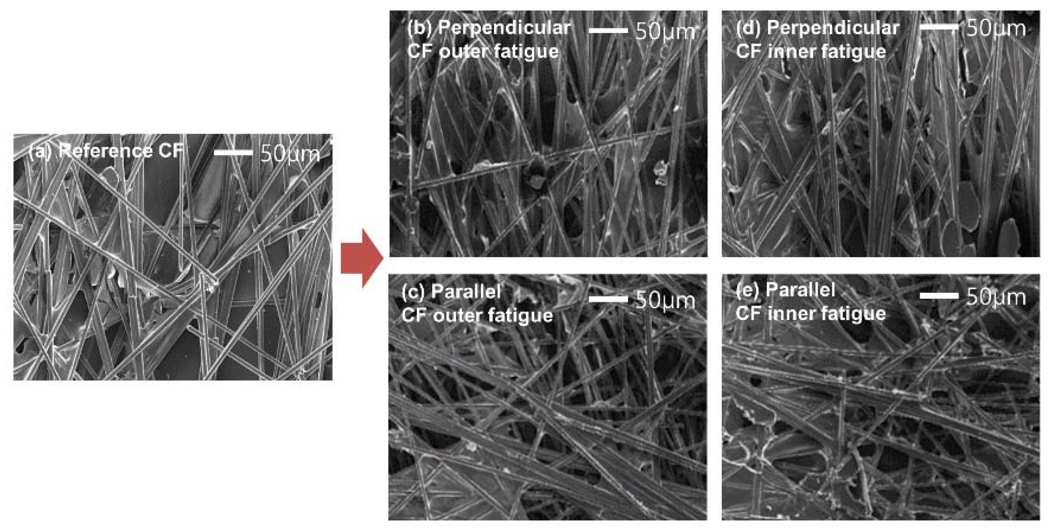
Figure 4a shows the FE-SEM image of the reference CFTF before the bending fatigue test, while the other FE-SEM images (
Figure 4b,e) are taken after the bending test. Comparison of the FE-SEM image before the bending fatigue tests with the images after the bending fatigue tests shows no difference in the surface and structure of the film. Although some FE-SEM images after the bending tests show the ends of CFs that seem to be broken, these similar structures are also found in the FE-SEM images before the bending fatigue tests (
Figure 4a). Moreover, when considering the result that there were no resistance changes after the bending fatigue tests, these findings show that these structures were not formed during the bending fatigue tests, but were generated because of the chopped CF that we used. This indicates that CFTF is suitable as a flexible planar heating element.
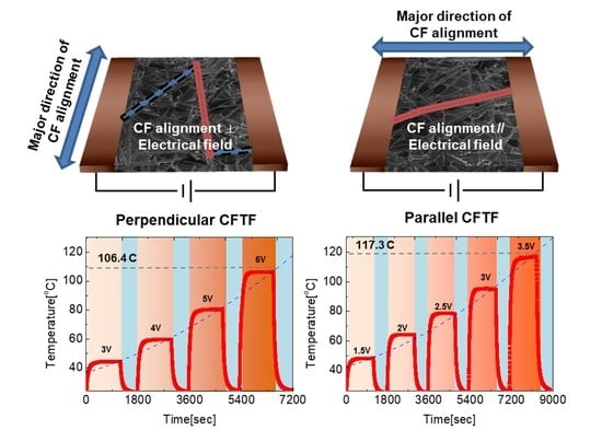
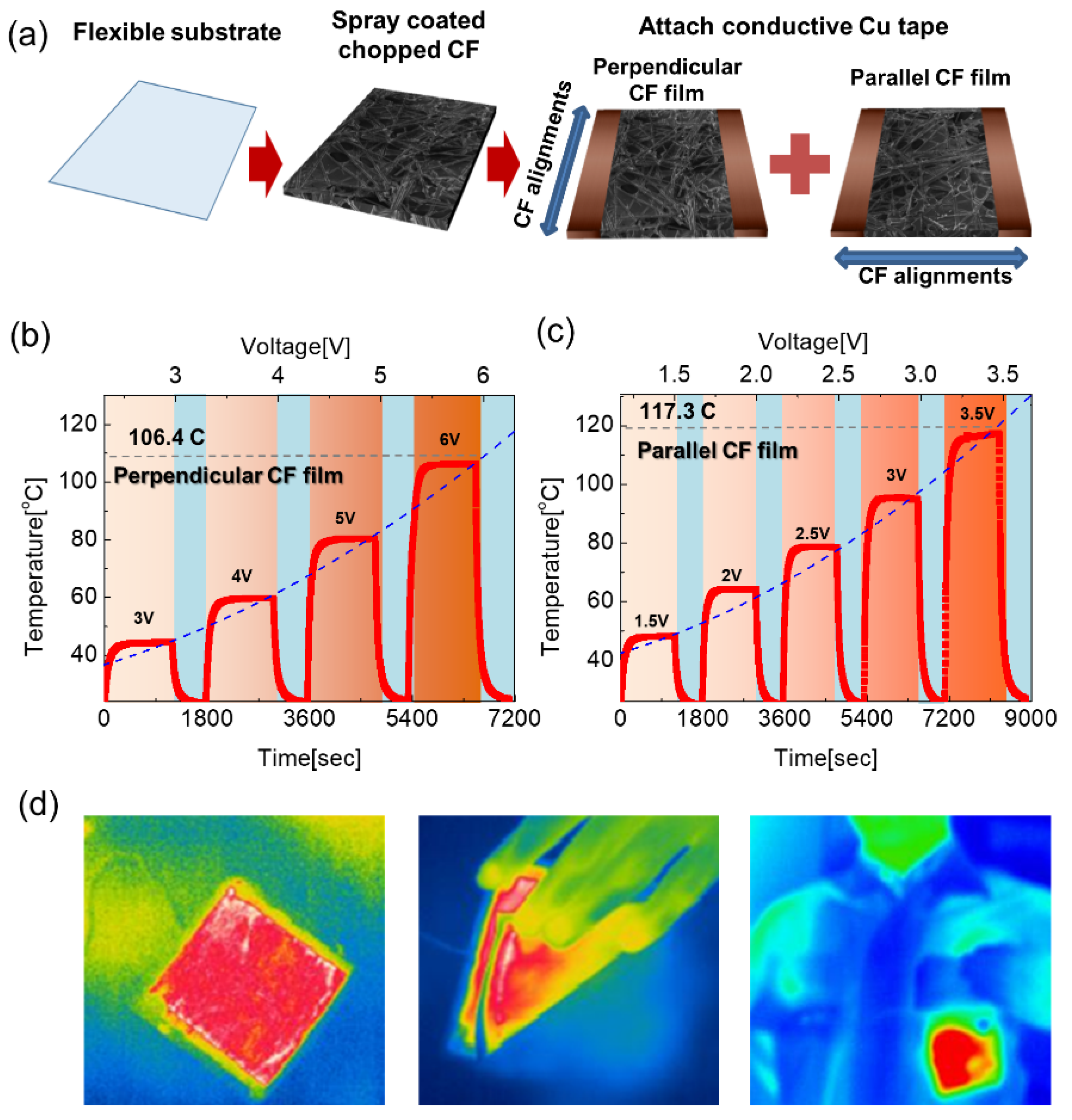
To confirm the effects of current flow direction and CF alignment direction on the heating performance of the flexible CFTF, we fabricated parallel CFTFH and perpendicular CFTFH. One is the applied voltage parallel to the CF alignments, while the other is the applied voltage perpendicular to CF alignments, respectively (
Figure 5a). DC voltage was supplied to the CFTFHs through the copper electrodes attached at the CFTF edge. The temperature was measured by using a thermocouple mounted on its surface, and by using an IR thermal camera. The graph in
Figure 5b is a graph showing the change in temperature over time, and its maximum value when the voltage is applied to the perpendicular CFTFs (25 mm
25 mm), the arrangement of CF is perpendicular to the applied voltage direction. As time passes, the CFTFH temperature gradually increased and reached a saturation temperature. At 6 V, the saturation temperature has risen to 106.4 °C.
Figure 5c shows the change in temperature over time and its maximum value when a voltage is applied to the Parallel CFTF (25 mm
25 mm), the arrangement of CFs is parallel to the applied voltage direction. As a result, it was confirmed that the temperature increased to 117.3 °C, which is over 100 °C, even though just 3.5 V was applied to the parallel CFTF. In these experiments, as discussed by Ko et al. [
42], the saturation temperature of the TFH is influenced by the sheet resistance of the TFH and applied voltage. When the sheet resistance of the TFH and the applied voltage are higher, the saturation temperature is higher (
Figure 5b,c), and these results indicate that electric energy is converted to Joule heating in the TFH [
42]. DC voltage (
V) is applied between the Cu contact electrodes of the CFTFH that has resistance (
R), and power (
P) is applied to the TFHs during heating for a certain amount of time (
); the generated heat (
), which is the summation of heat loss due to convection in air (
), heat loss due to conduction (
), and heat loss due to radiation (
) from CFTFHs, can be expressed by the following equation [
42]:
In these heating tests, heat loss due to conduction was negligible, because the CFTFHs were not in contact with a good thermal conductor. Therefore, air convection is the main path of heat dissipation in the CFTFHs, and the amount of heat transport by convection in the air is given by these equations [
1,
43]:
where,
and
are the convective heat transfer coefficient and the surface area, and
and
are the saturation and initial temperature, respectively. These equations show that the heat transport by convection in air and the saturation temperature of TFHs are proportional to the square f the input DC voltage (V), and inversely proportional to the resistance (R). Therefore, it was confirmed that the CFTFHs generated high temperature because of its low sheet resistance. In particular, the CFTFs in which CFs are aligned parallel to the applied voltage direction showed the high exothermic performance of 117.3 °C under 3.5 V, while the perpendicular CFTFH showed 106.4 °C under 6 V, which shows relatively low performance, compared to the parallel CFTFH. Our study shows that the anisotropic percolation network of CFTFs have more direct conduction pathways in the direction parallel to the CF Alignment direction than the direction perpendicular to the CF alignment direction, and this difference makes the sheet resistance different between the directions. Therefore, the saturation temperatures of CFTFHs fabricated by the RTR spray coating that has an anisotropic percolation network are closely related to their alignment between the direction of the applied voltage and the CF alignments. These results demonstrate that the parallel CFTFH generates larger thermal energy at lower voltage, because it has lower resistance than the perpendicular CFTFH, like the prediction from the result of the experiment that measured the electrical characteristics. Based on these discoveries about CFTFH fabricated by the RTR spray coating, we can conclude that this shows that the Parallel CFTFH, in which the direction of the voltage is parallel to the direction of the CFs alignment, is more suitable and efficient as a heater. Moreover, we confirmed the application possibility by applying it to real clothing. IR images of
Figure 5d demonstrate CFTFHs and CFTFH-attached clothing have a uniform heating characteristic over the entire heating surface; and even if bent, it can generate heat without problem. Therefore, we conclude that CFTFHs fabricated by RTR spray coating form a flexible heating element with good applicability and strong durability and more efficient when the applied voltage is parallel to the CF alignment direction.
3. Experimental
The carbon fibers (CFs) were spray coated on a flexible polyethylene terephthalate (PET) substrate with a constant rolling speed of roll-to-roll system in the air. To fabricate a CF solution, chopped PAN-based carbon fibers (TKS70, Taekwang, Seoul, Korea) with a diameter of 7 μm and a length of 6 mm were used. At a weight ratio of 1:9, CFs were mixed with a solution of 2 wt.% of xanthan gum and 98 wt.% of DI water. The amount of sprayed solution is 15 g, the distance between the substrate and the nozzle is 200 mm, diameter of the nozzle is 1 mm and speed of the winder is 5 mm/s. The electrical properties of MAM electrodes were examined by a four-point probe (FPP-HS8, DASOL ENG, CheongJu-si, Korea) and Hall measurements (HMS-4500, Ecopia, Anyang-si, Korea). Field emission scanning electron microscopy (FESEM: JSM-7600F, JEOL, Tokyo, Japan) was used to investigate the surface morphology before and after bending tests. To demonstrate the feasibility of CFTFs, we fabricated CFTF based TFHs and analyzed heating profiles of these devices. The temperature of the TFHs was measured by a contact thermocouple and non-contact IR thermal imager (A35sc, FLIR, Wilsonville, OR, USA). Drawings in manuscript were using a RHINO 6 (6th version, Robert McNeel & Associates, Seattle, WA, USA, 2019) and a Powerpoint (2016 version, Microsoft, Redmond, WA, USA, 2016).


