Automatic Code Generation of MVC Web Applications


Abstract
1. Introduction
2. Background
- Structure Diagrams (describe the structure of a system): Class Diagram, Component Diagram, Object Diagram, Profile Diagram, Composite Structure Diagram, Deployment Diagram, Package Diagram.
- Behavior Diagrams (describe the behavior of a system): Activity Diagram, Use Case Diagram, State Machine Diagram.
- Interaction Diagrams (relate the structural part of a system to the behavioral part): Sequence Diagram, Communication Diagram, Timing Diagram.
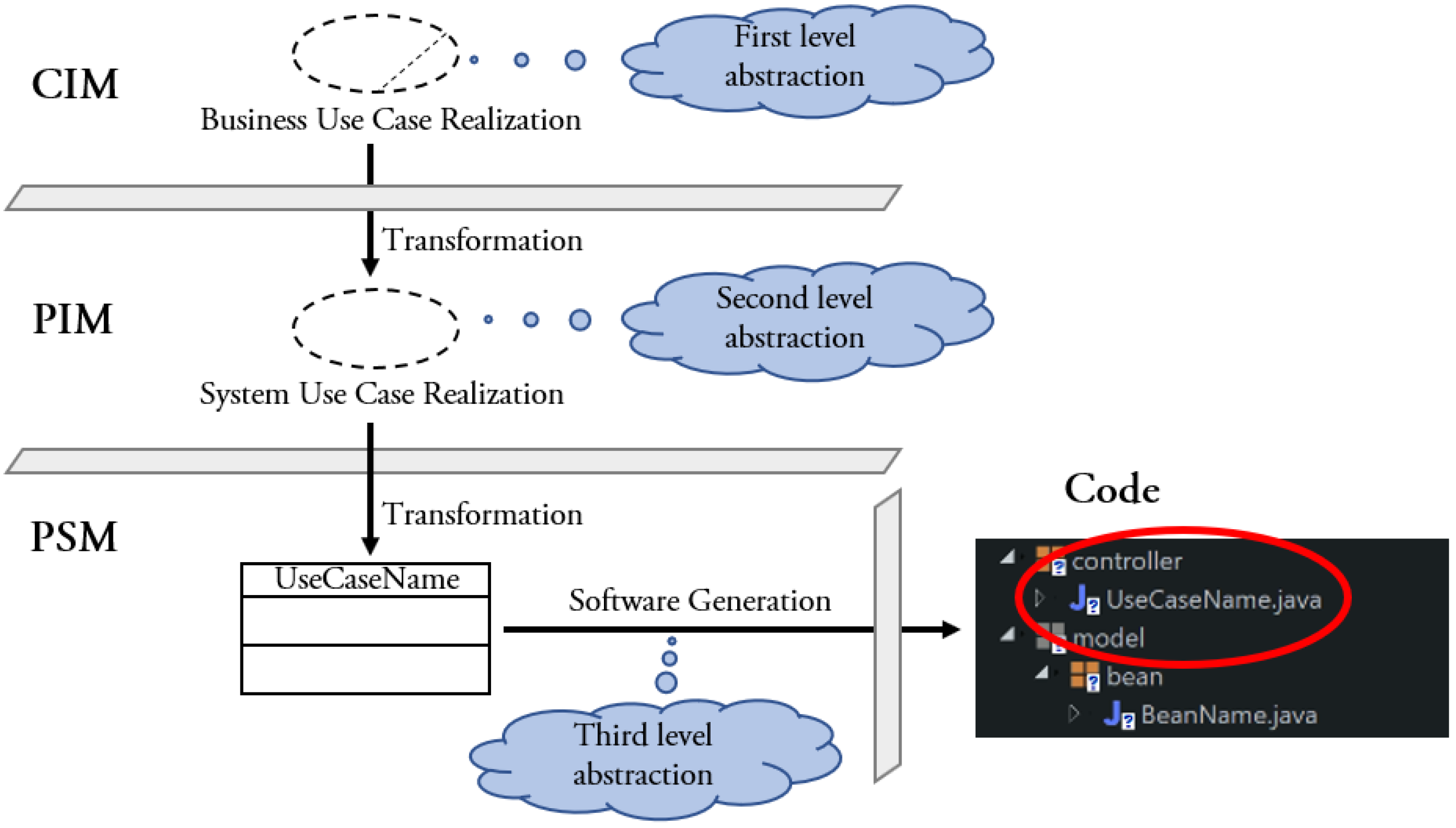
- Computation Independent Model (CIM) – It ignores details of the structure of the software system. A CIM is sometimes called a model.
- Platform Independent Model (PIM) – It exhibits a certain degree of platform independence so as to be suitable for use with a number of different platforms of similar type.
- Platform Specific Model (PSM) – It combines the specifications in the PIM with the details that specify how the software system uses a particular type of platform.
3. The Proposed Software Development Process
3.1. Overview of the Proposal
- Domain Specific Languages. DSLs allow textual or graphical representations of custom domains. DSLs promise high productivity, provided that the target environment can be clearly defined.
- UML. UML provides standard techniques (e.g., use cases, class diagrams, sequence diagrams, etc.) for modeling behavior and structure of the applications. Generating code from a UML model is possible, provided that the target environment is well defined.
- Database. Many tools generate (parts of) applications from the database structure. This approach have important limitations. The generated application instead of providing support for the work processes to be automated, will mimic the database and thus will be data-centric. Besides that, in the context of service orientation and cloud computing, many applications do not even have their own database.
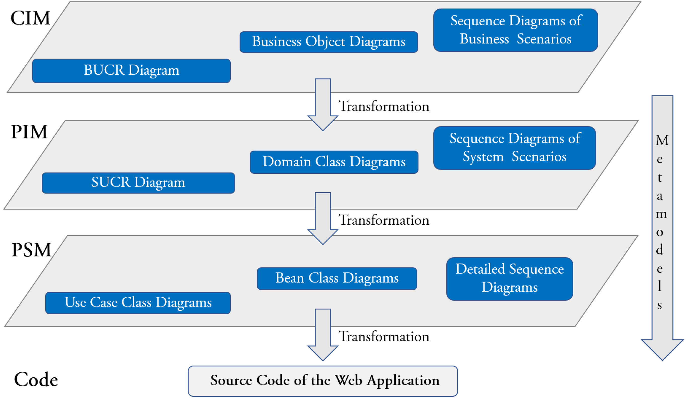
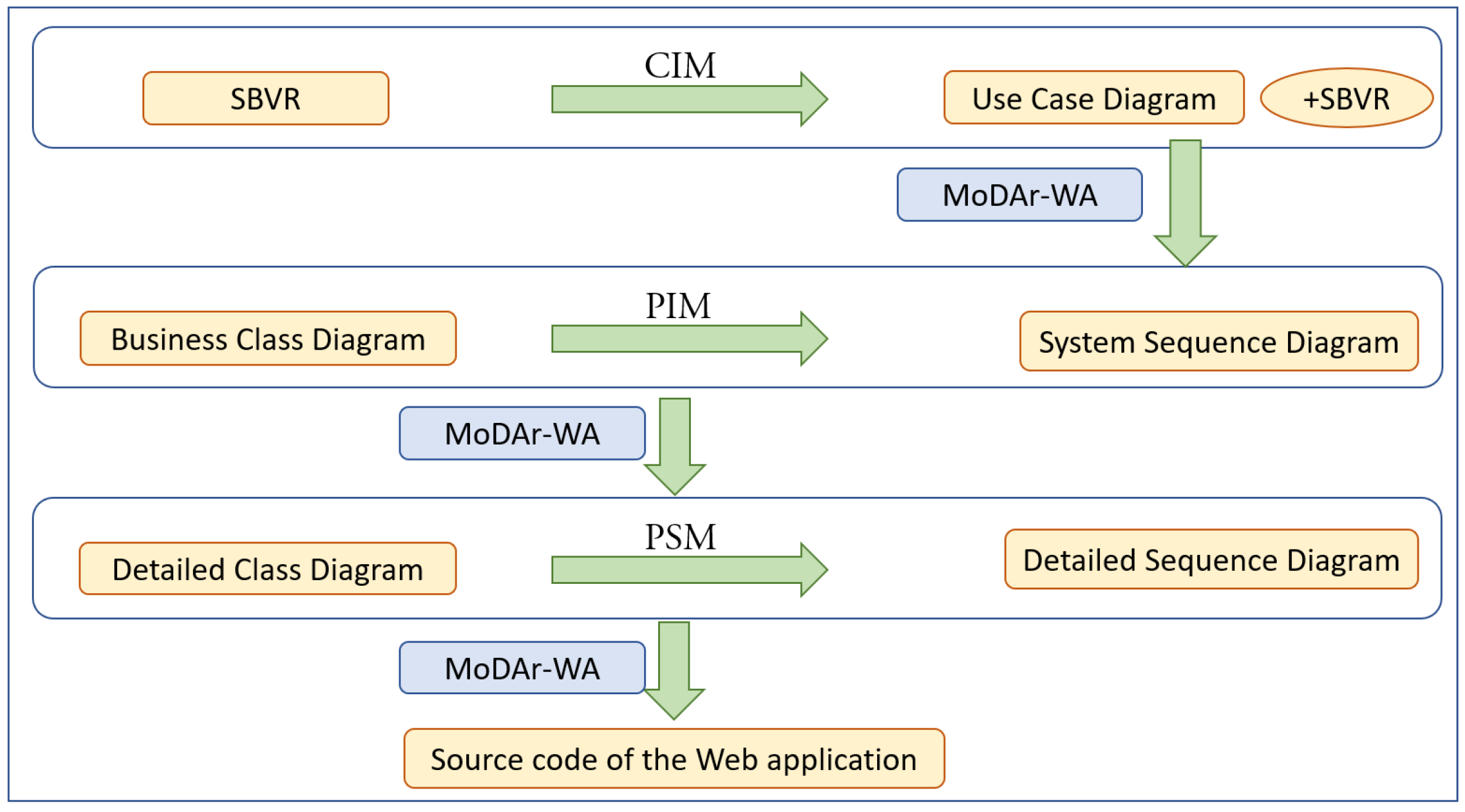
3.2. Description of the Software Development Process
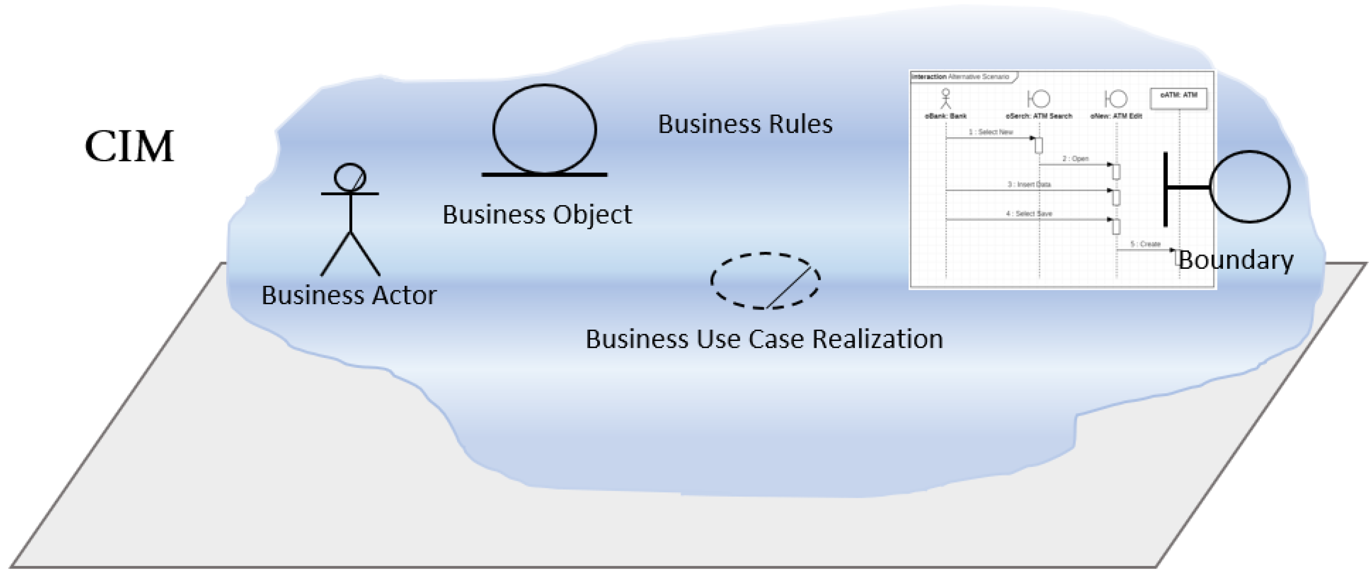
3.2.1. Computational Indepedent Model (CIM)
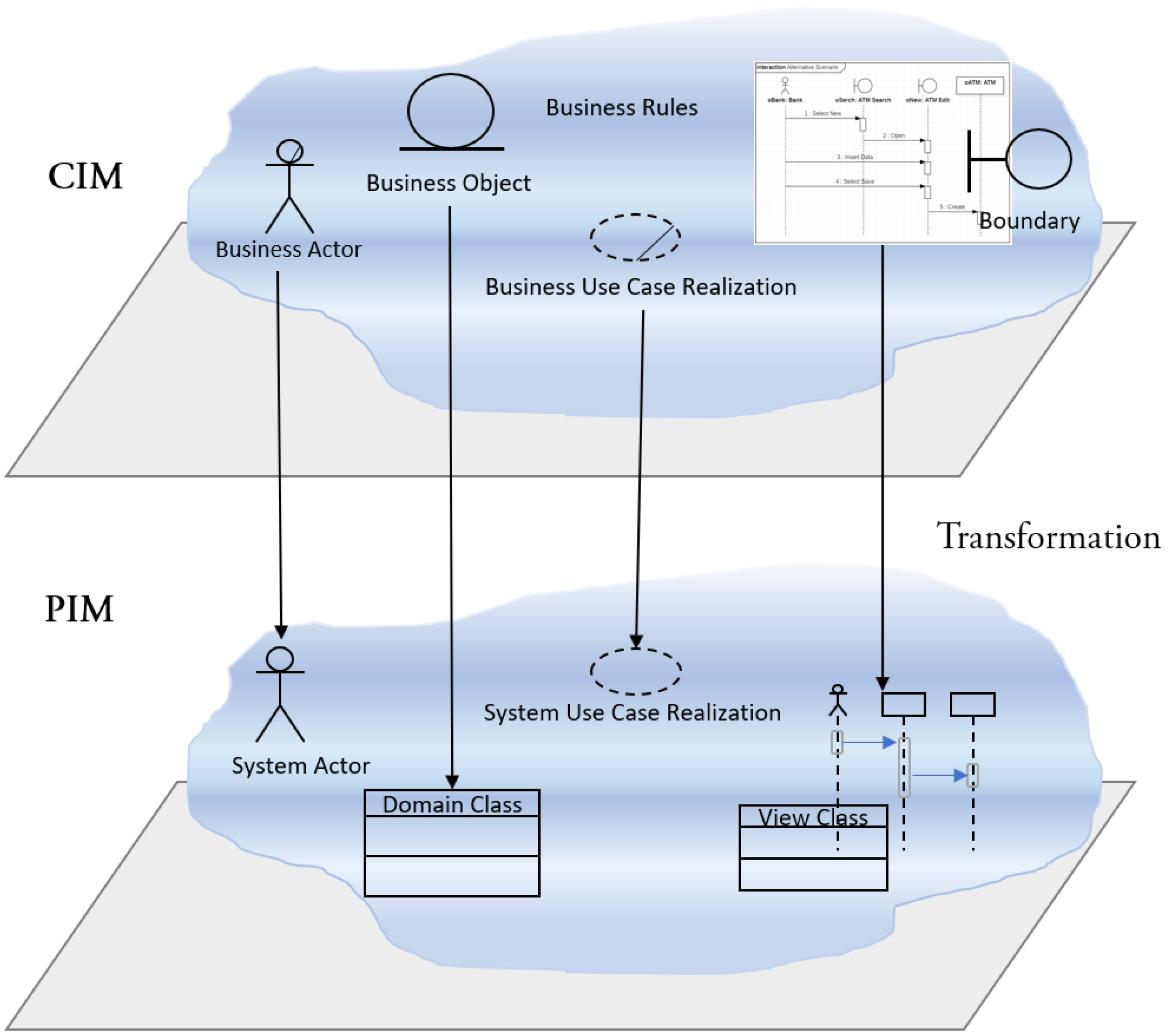
3.2.2. Platform Independent Model (PIM)
- of the Business Actors, Business Objects and Business UC Realizations that participate in the automation process (they are the only ones having a Boolean tag set to True), so they have to be included in the system model;
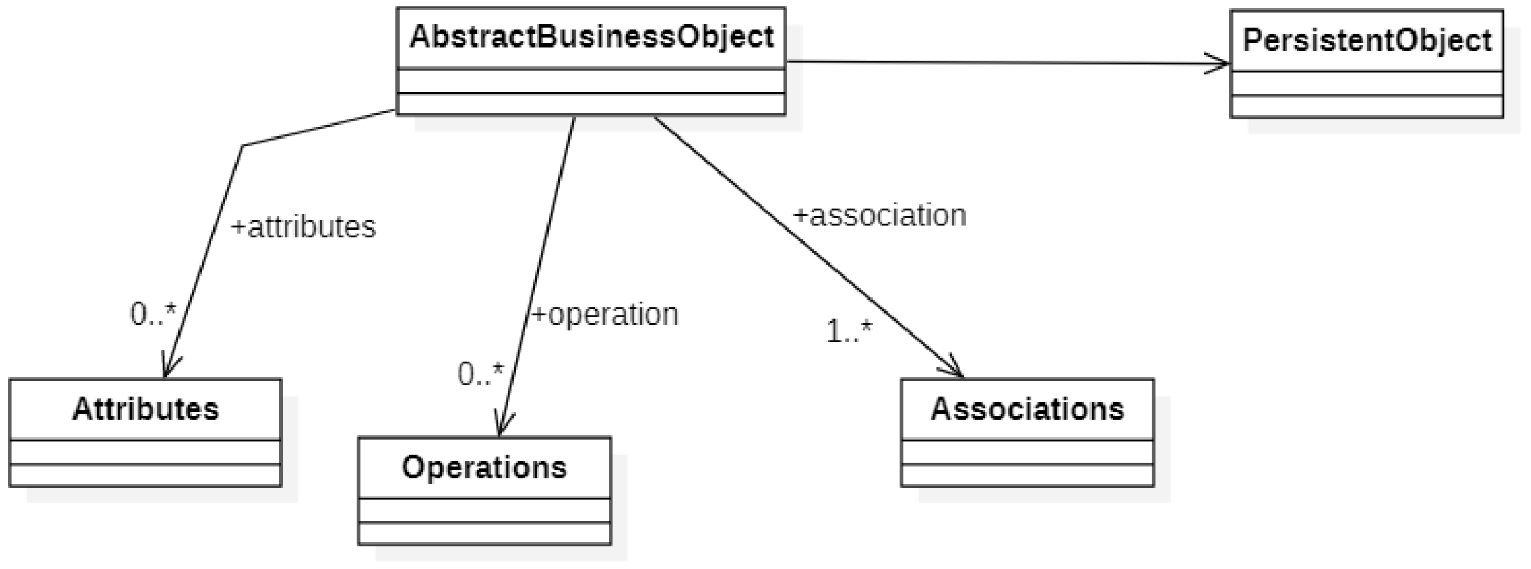
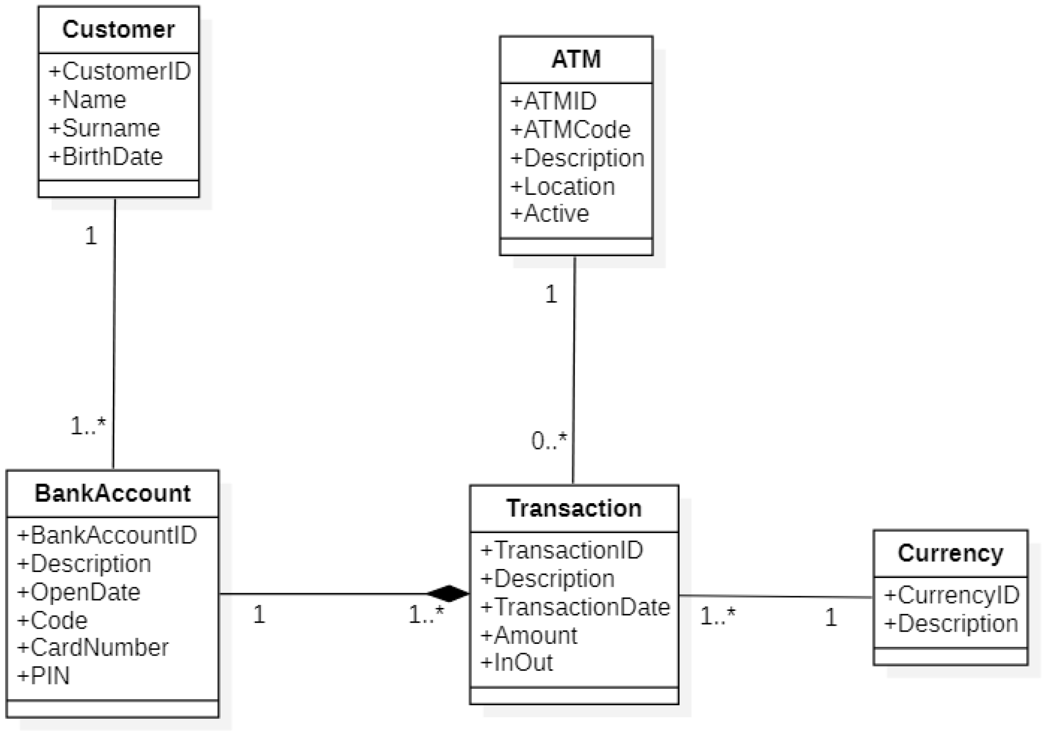
- of the Business Objects into Domain Classes;
- of the Business Actors into System Actors;
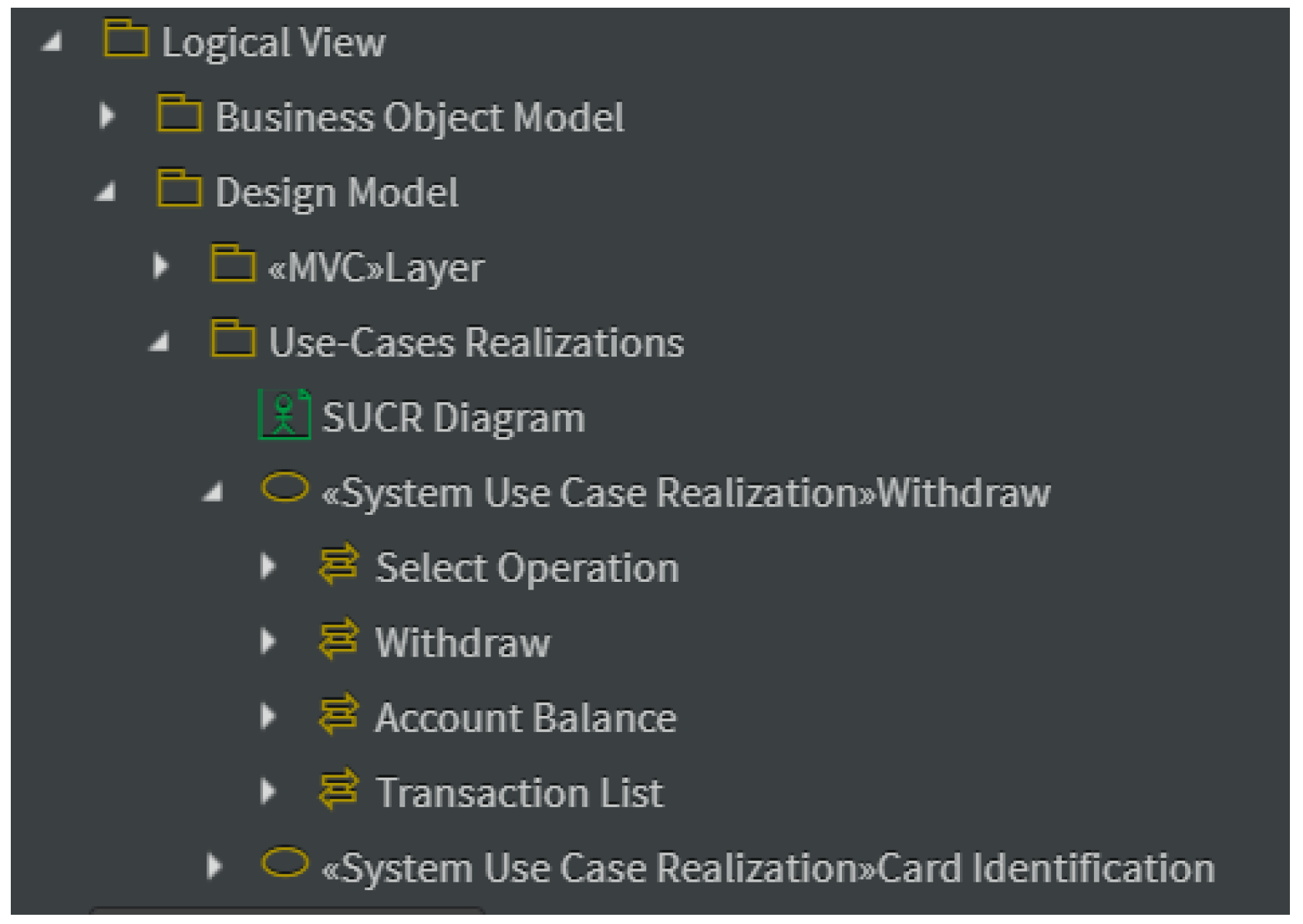
- of the Business UC Realizations whose tag is true, in as many System UC Realizations;
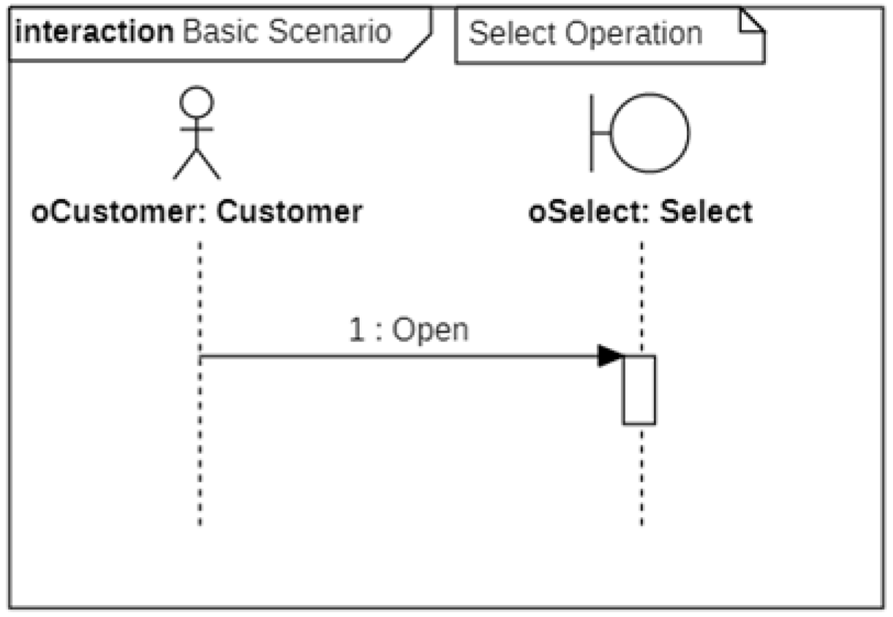
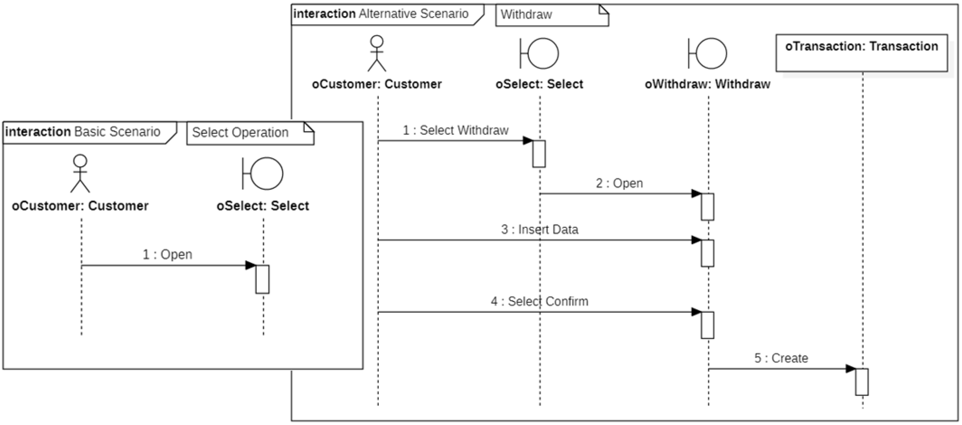
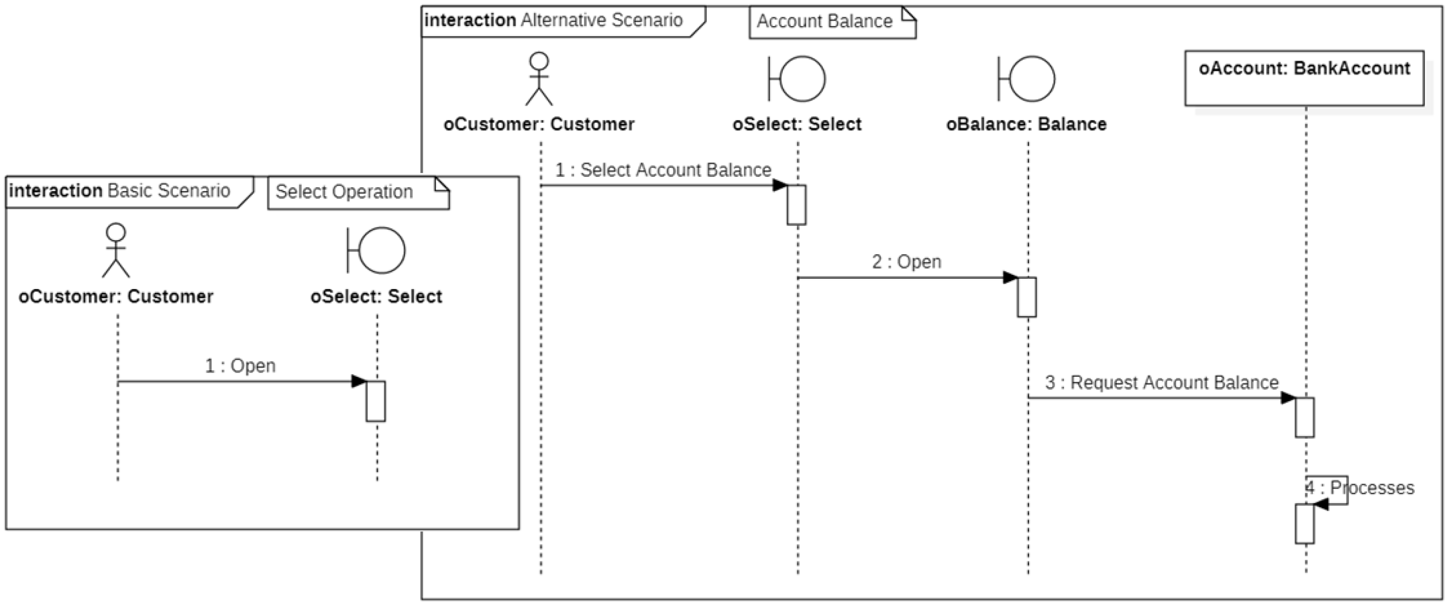
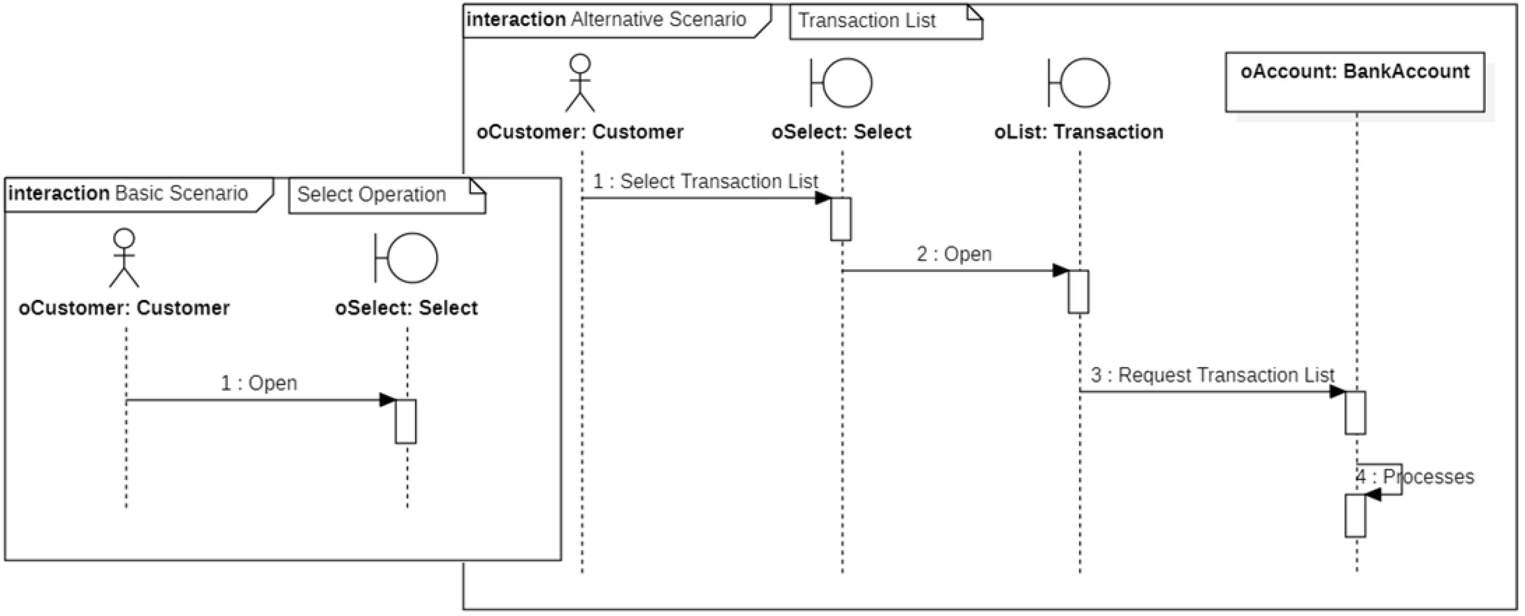
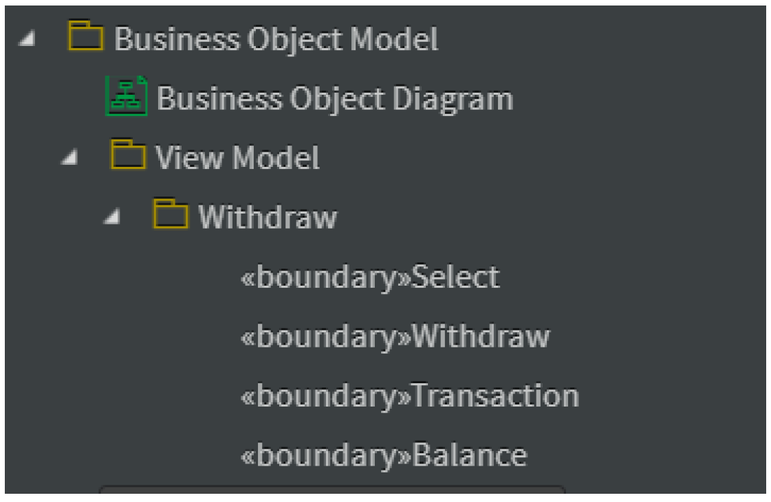
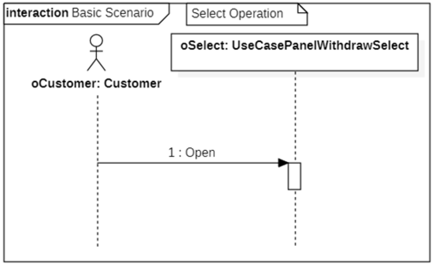
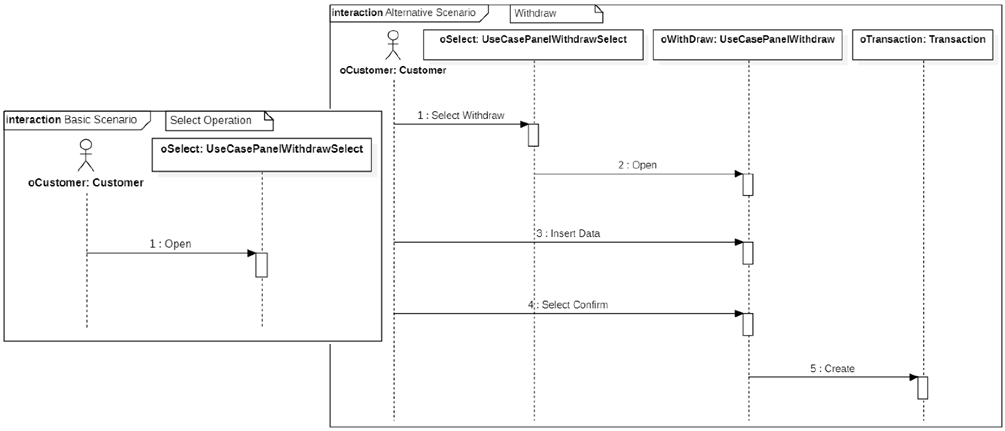
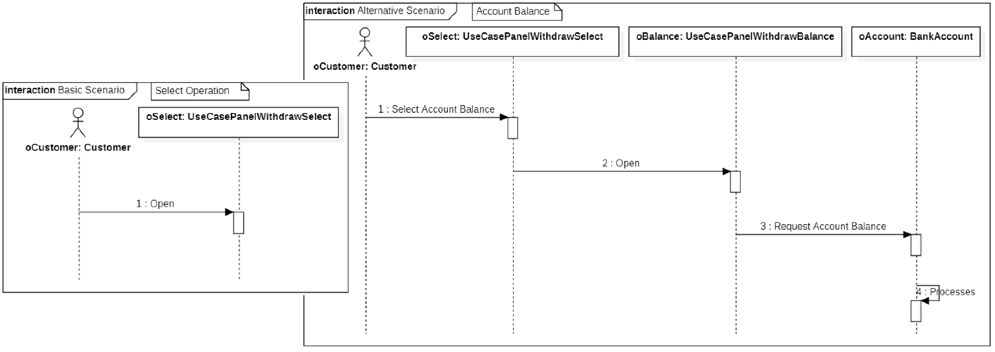
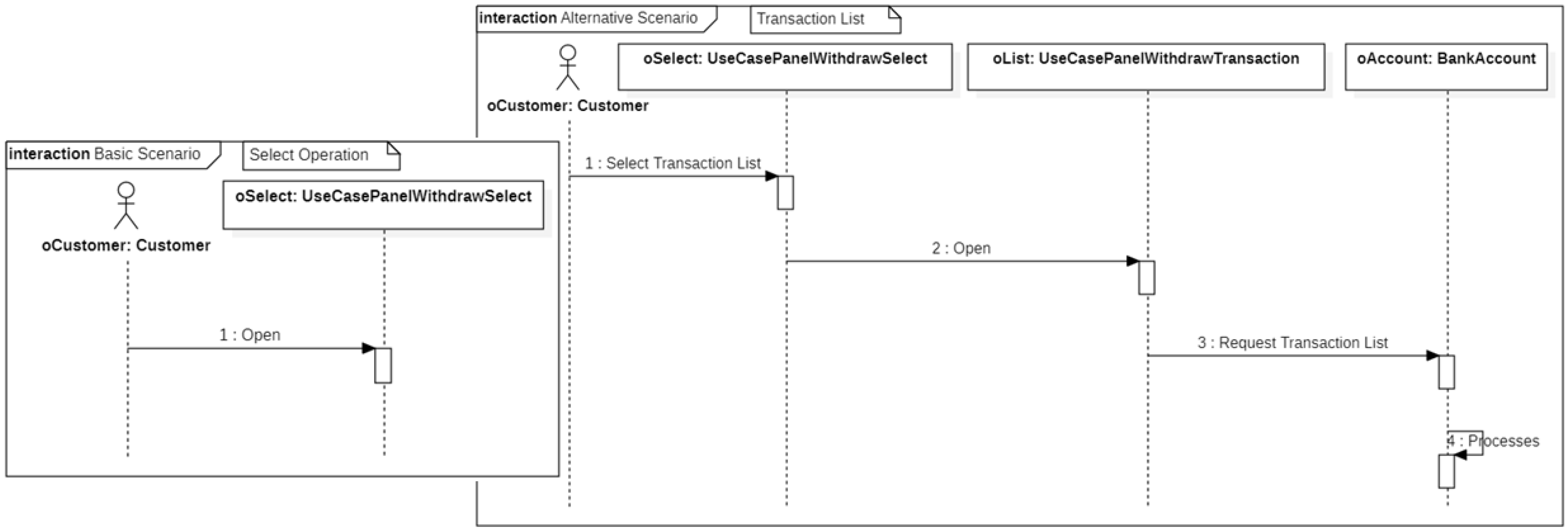
- of the business scenario (modeled as Sequence diagrams) into a system scenario (modeled as Sequence diagrams): the Boundary classes (of the CIM) become View classes (at PIM).
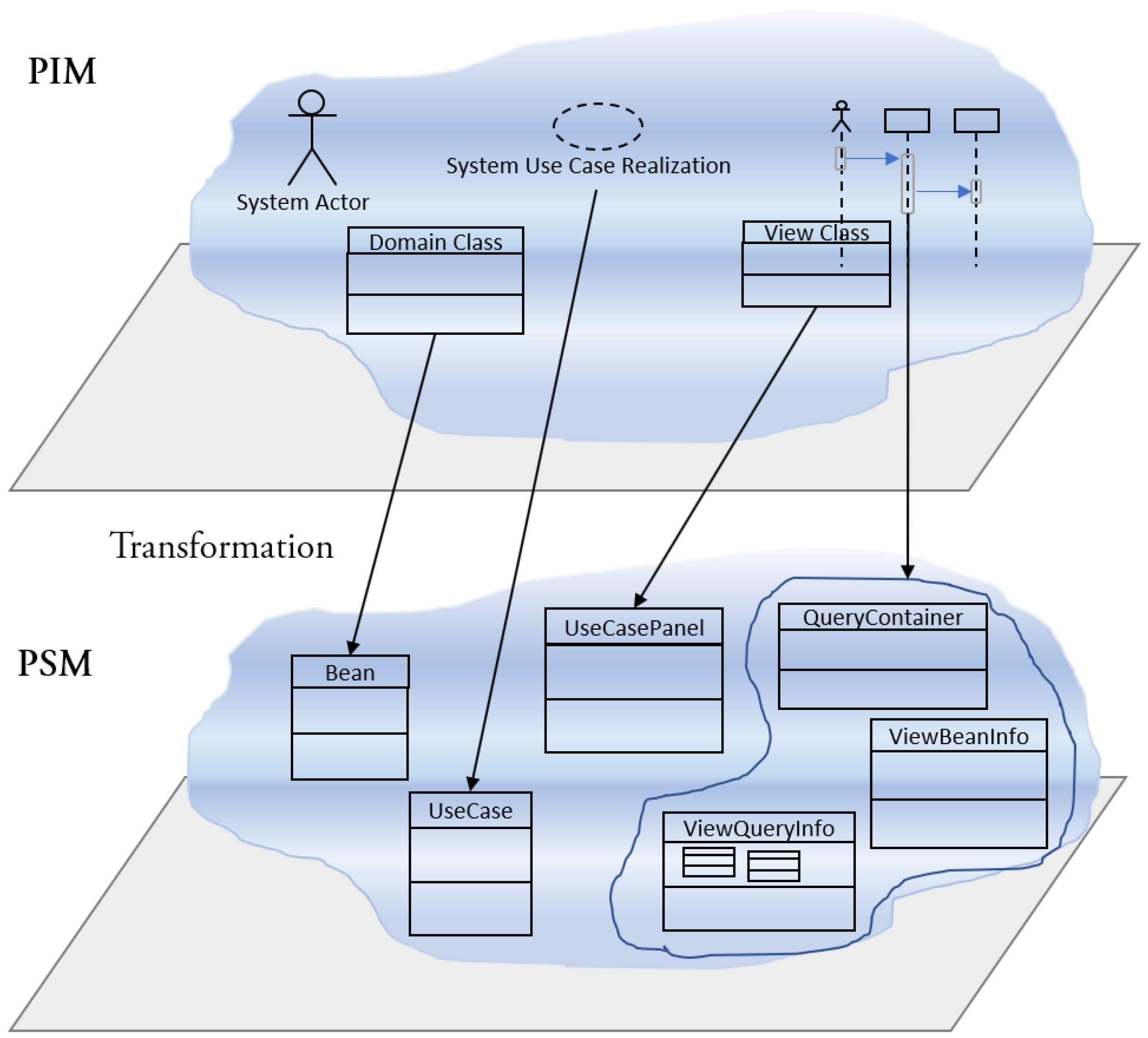
3.2.3. The Platform Specific Model (PSM)
- about the aspect:
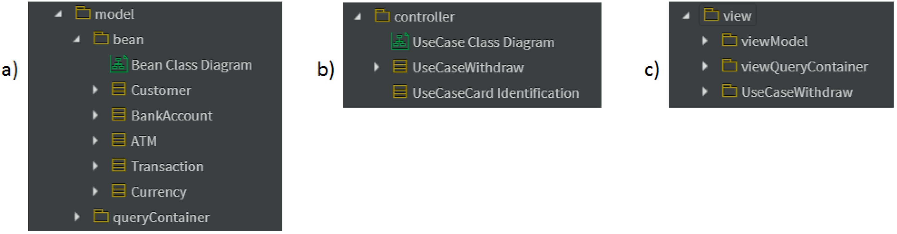
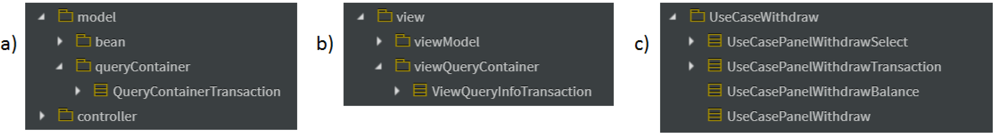
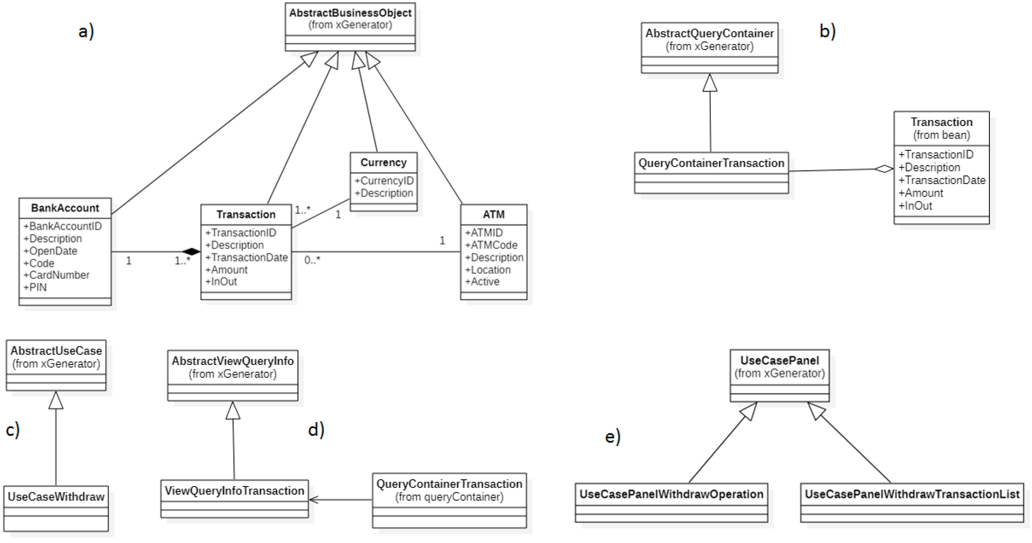
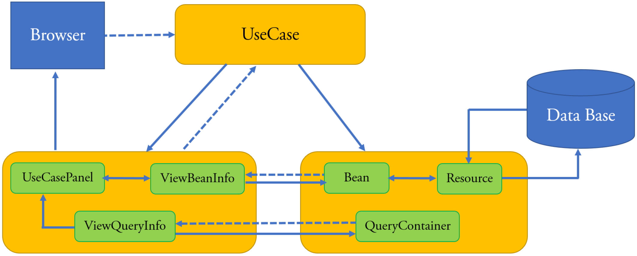
- transformation of each Domain Class into a Bean class;
- transformation of the View classes of present in the scenarios of the System UC Realizations into a QueryContainer class;
- about the aspect:
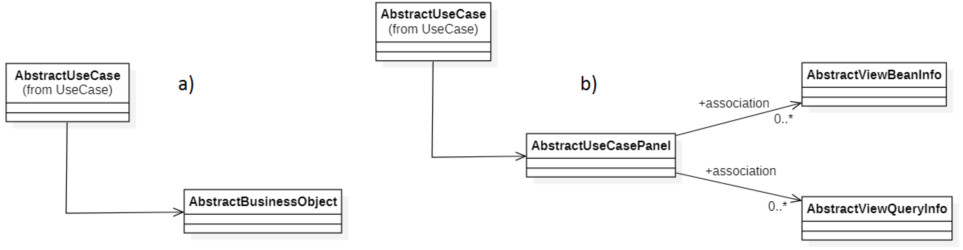
- transformation of the System UC Realizations into UseCase classes;
- about the Graphical User Interface:
- transformation of the View classes into UseCasePanel classes;
- transformation of the Views of editing present in the scenarios of the System UC Realizations into ViewBeanInfo classes;
- creation of a ViewQueryInfo class for each QueryContainer class.
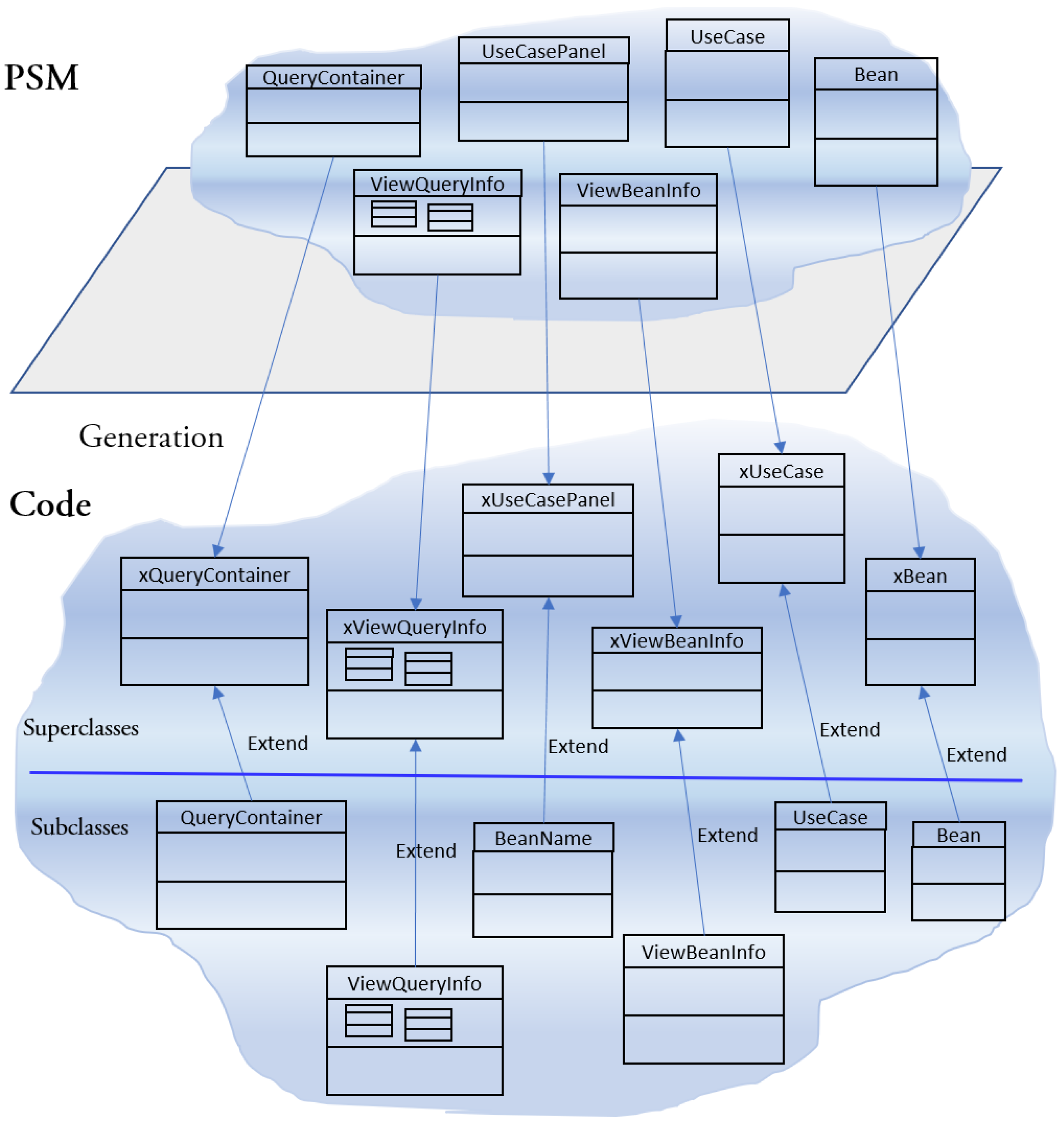
3.2.4. The Code Model (PSM to Code)
3.3. Our Meta-Models
3.4. Discussion
4. Case Study: The Automated Teller Machine (ATM) Project
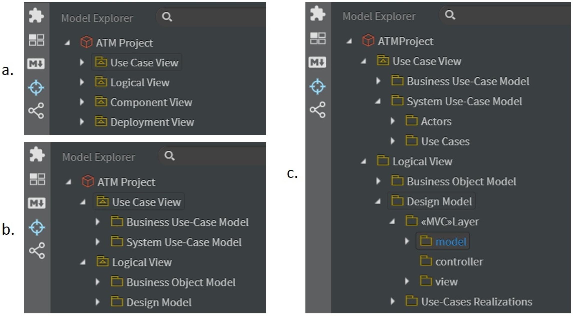
- the artefacts of the CIM are placed into the packages Business Use-Case Model and Business Objet Model (Figure 12c) and in the package View Model of the latter;
- the artefacts of the PIM are placed into the packages Actors and Use Cases internal to the package System Use-Case Model and in the packages Layer and Use-Case Realizations of the package Design Model (Figure 12c);
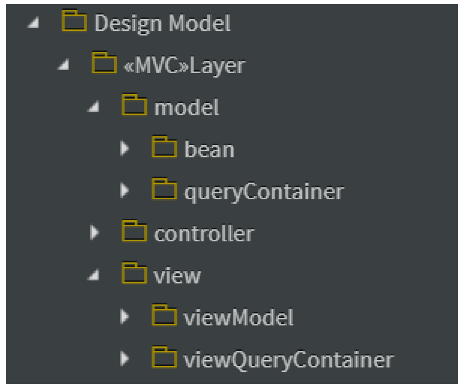
- the artefacts of the PSM are placed into the packages Layer and Use-Case Realizations of the package Design Model. The package Layer contains the packages to model the classes of the extended MVC pattern (Appendix A).
4.1. CIM
4.2. PIM
4.3. PSM
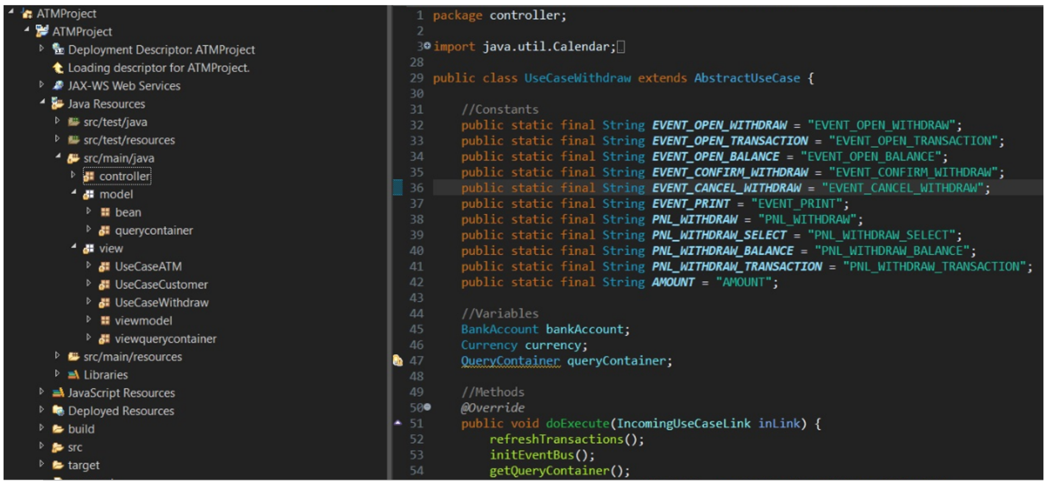
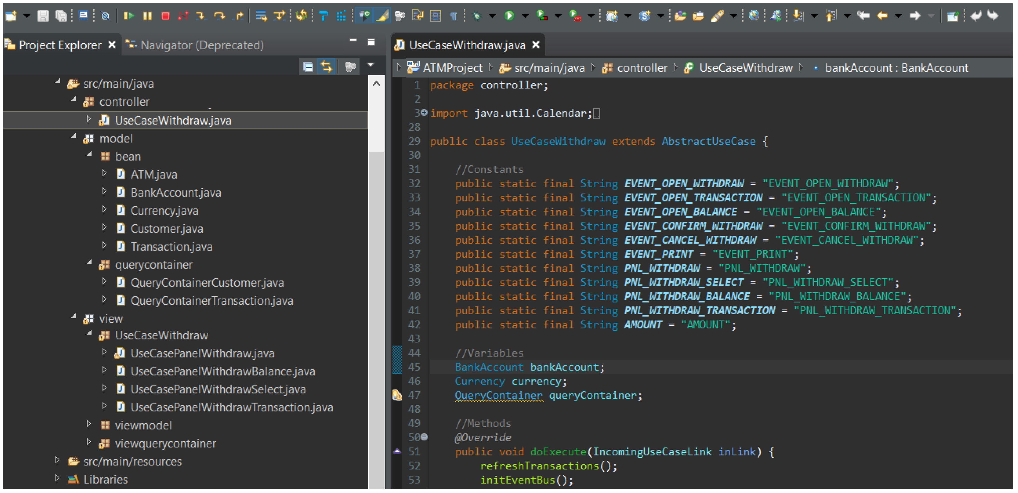
4.4. The Code
5. Related Work
5.1. Code Generation within MDE
5.2. Code Generation within MDA
5.3. Comparison with an MDA Approach for Web Application Development
6. Conclusions and Future Work
Author Contributions
Funding
Conflicts of Interest
Abbreviations
| BCD | Business Class Diagram |
| BUCR | Business UC Realization |
| CIM | Computation Independent Model |
| HTML | HyperText Markup Language |
| MDA | Model Driven Architecture |
| MDE | Model Driven Engineering |
| MVC | Model-View-Controller |
| OMG | Object Management Group |
| PIM | Platform Independent Model |
| PSM | Platform Specific Model |
| QVT | Query View Transformation |
| SBVR | Semantic Business Vocabulary and Business Rules |
| SUCR | System UC Realization |
| UML | Unified Modeling Language |
| UC | Use Case |
| UCD | Use Case Diagram |
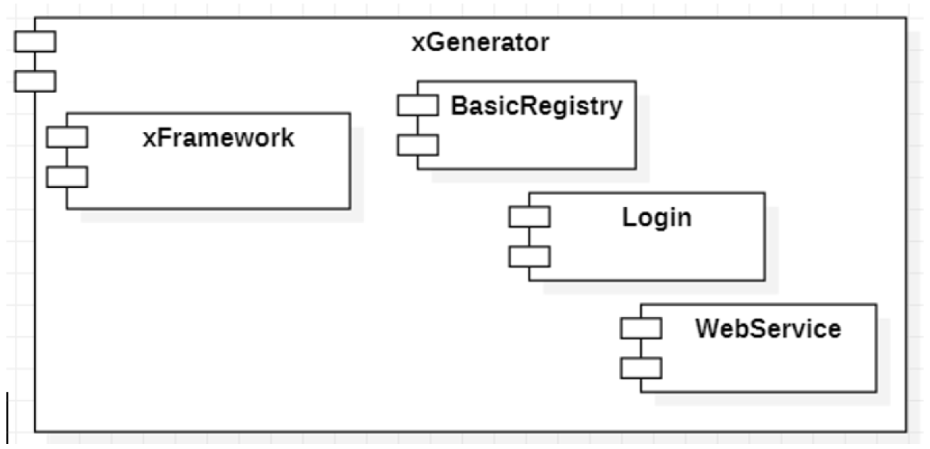
Appendix A. xGenerator
- the business model is “pure”, in the sense that it is not contaminated by information about layers different from the business one. A pure model is composed of business objects without any reference to features related to the data sources (i.e., databases, XML files, and Web Services) or to the interface (i.e., textBox, Form, checkBox);
- the notion of use case acts as a link between the analysis model and the coding of the behavioral aspect.


| Component Name | Number of Classes | Number of Methods | Lines of Code |
|---|---|---|---|
| xFramework | 843 | 6613 | 67,931 |
| Additional components | 212 | 1293 | 15,441 |
| xGenerator | 468 | 3090 | 56,467 |
| Grand Total | 1523 | 10,996 | 139,839 |
- Eclipse IDE for Java EE Developers;
- Apache Maven for the project’s build and library management;
- Vaadin Plugin to compile the GUI;
- Jetty: Client http used for carrying out automatic tests of the build;
- the Apache Subversion (SVN) software versioning and revision control system;
- StarUML to build UML 2.x diagrams.

References
- Herrero, J.L.; del Barco, P.C. A model-driven approach to develop high performance web applications. J. Syst. Softw. 2013, 86, 3013–3023. [Google Scholar] [CrossRef]
- OMG Unified Modeling Language (OMG UML), Version 2.5.1 OMG Document Number: Formal/2017-12-05, December 2017. Available online: https/www.omg.org/spec/UML/ (accessed on 5 March 2020).
- Paolone, G.; Clementini, E.; Liguori, G. A methodology for building enterprise Web 2.0 Applications. In Proceedings of the Modern Information Technology in the Innovation Processes of the Industrial Enterprises (MITIP), Prague, Czech Republic, 12–14 November 2008; pp. 228–233. [Google Scholar]
- Armour, F.; Miller, G. Advanced Use Case Modeling: Software Systems; Addison-Wesley Object Technology Series; Addison-Wesley: New York, NY, USA.
- Ciccozzi, T.; Malavolta, I.; Selic, B. Execution of UML models: A systematic review of research and practice. Softw. Syst. Model. 2019, 18, 2313–2360. [Google Scholar] [CrossRef]
- Paolone, G.; Di Felice, P.; Liguori, G.; Cestra, G.; Clementini, E. A Business Use Case Driven Methodology—A Step Forward. In Proceedings of the 5th International Conference on Evaluation of Novel Approaches to Software Engineering (ENASE), Athens, Greece, 22–24 July 2010; pp. 221–226. Available online: https://pdfs.semanticscholar.org/70c0/819791d0f68bdf624c18c8a5a2f2a512e9f9.pdf (accessed on 7 April 2020).
- Paolone, G.; Di Felice, P.; Liguori, G.; Cestra, G.; Clementini, E. Use Case Double Tracing Linking Business Modeling to Software Development. In Information Technology and Innovation Trends in Organizations; D’Atri, A., Ferrara, M., George, J., Spagnoletti, P., Eds.; Physica-Verlag HD: Berlin/Heidelberg, Germany, 2011; pp. 187–195. Available online: https://doi-org.univaq.clas.cineca.it/10.1007/978-3-7908-2632-6_22 (accessed on 5 March 2020).
- Jörges, S. Construction and Evolution of Code Generators: A Model-Driven and Service-Oriented Approach; Springer: Berlin/Heidelberg, Germany, 2013. [Google Scholar]
- Van Der Straeten, R.; Mens, T.; Van Baelen, S. Challenges in Model-Driven Software Engineering; Chaudron, M.R.V., Ed.; MODELS 2008 Workshops, LNCS 5421; Springer: Berlin/Heidelberg, Germany, 2009; pp. 35–47. [Google Scholar]
- Mohagheghi, P.; Gilani, W.; Stefanescu, A.; Fernandez, M.A. An empirical study of the state of the practice and acceptance of model-driven engineering in four industrial cases. Empir Softw. Eng 2013, 18, 89–116. [Google Scholar] [CrossRef]
- Kulkarni, V. Model Driven Software Development. A Practitioner Takes Stock and Looks into Future. In Modelling Foundations and Applications; Gorp, P.V., Ritter, T., Rose, L.M., Eds.; ECMFA 2013, Lecture Notes in Computer Science, Volume 7949; Springer: Berlin/Heidelberg, Germany, 2013. [Google Scholar] [CrossRef]
- Cuadrado, J.S.; Izquierdo, J.L.C.; Molina, J.G. Applying model-driven engineering in small software enterprises. Sci. Comput. Program. 2014, 89, 176–198. [Google Scholar] [CrossRef]
- Hutchinson, J.; Whittle, J.; Rouncefield, M. Model-driven engineering practices in industry: Social, organizational and managerial factors that lead to success or failure. Sci. Comput. Program. 2014, 89, 144–161. [Google Scholar] [CrossRef]
- Cabot, J.; Kolovos, D.S. Human Factors in the Adoption of Model-Driven Engineering: An Educator’s Perspective; ER 2016 Workshops, LNCS; Link, S., Trujillo, J.C., Eds.; Springer: Berlin/Heidelberg, Germany, 2016; Volume 9975, pp. 207–217. [Google Scholar] [CrossRef]
- Mahmood, H.; Jilani, A.A.A.; Rauf, A. A Lightweight Framework for Automated Model-to-Code Transformation. In Proceedings of the IEEE 14th International Multitopic Conference, Harachi, Pakistan, 22–24 December 2011. [Google Scholar]
- Mussbacher, G.; Amyot, D.; Breu, R.; Bruel, J.-M.; Cheng, B.H.C.; Collet, P.; Combemale, B.; France, R.B.; Heldal, R.; Hill, J.; et al. The Relevance of Model-Driven Engineering Thirty Years from Now. In Model-Driven Engineering Languages and Systems; MODELS 2014. Lecture Notes in Computer Science, Volume 8767; Dingel, J., Schulte, W., Ramos, I., Abrahão, S., Insfran, E., Eds.; Springer: Cham, Switzerland, 2014. [Google Scholar] [CrossRef]
- Bucchiarone, A.; Cabot, J.; Paige, J.R.F.; Pierantonio, A. Grand challenges in model-driven engineering: An analysis of the state of the research. Softw. Syst. Model. 2020, 19, 5–13. [Google Scholar] [CrossRef]
- Sebastián, G.; Gallud, J.A.; Tesoriero, R. Code generation using model driven architecture: A systematic mapping study. J. Comput. Lang. 2020, 56, 100935. [Google Scholar] [CrossRef]
- Pop, D.P.; Altar, A. Designing an MVC Model for Rapid Web Application Development 24th DAAAM International Symposium on Intelligent Manufacturing and Automation, 2013. Procedia Eng. 2014, 69, 1172–1179. [Google Scholar] [CrossRef]
- Kruchten, P. The Rational Unified Process: An Introduction, 3rd ed.; Addison-Wesley Professional; Addison-Wesley Object Technology Series; Addison-Wesley: New York, NY, USA, 2003. [Google Scholar]
- Object Management Group, MDA Guide Version 1.0.1, OMG Document omg/2003-06-01, Needham, MA, 12 June 2003. Available online: https://www.omg.org/news/meetings/workshops/UML_2003_Manual/00-2_MDA_Guide_v1.0.1.pdf (accessed on 5 March 2020).
- Kleppe, A. Software Language Engineering: Creating Domain-Specific Languages Using Metamodels, 1st ed.; Addison-Wesley: New York, NY, USA, 2008; ISBN 9780321553454. [Google Scholar]
- Steffen, B.; Margaria, T.; Wagner, C. Round-Trip Engineering. In Encyclopedia of Software Engineering; Taylor & Francis: Essex, UK, 2010; pp. 1044–1055. [Google Scholar] [CrossRef]
- Vlissides, J.M. Pattern Hatching: Design Patterns Applied; Addison-Wesley: New York, NY, USA, 1998; ISBN 0201432935. [Google Scholar]
- Sunitha, E.V.; Samuel, P. Translation of behavioral models to source code. In Proceedings of the 12th International Conference on Intelligent Systems Design and Applications (ISDA), Kochi, India, 27–29 November 2012; pp. 598–604. [Google Scholar]
- Sunitha, E.V.; Samuel, P. Object constraint language for code generation from activity models. Inf. Softw. Technol. 2018, 103, 92–111. [Google Scholar] [CrossRef]
- Kahani, N.; Bagherzadeh, M.; Cordy, J.R.; Dingel, J.; Varró, D. Survey and classification of model transformation tools. Softw. Syst. Model. 2019, 18, 2361–2397. [Google Scholar] [CrossRef]
- Parada, A.G.; Siegert, E.; de Brisolara, L.B. Generating Java code from UML Class and Sequence Diagrams. In Proceedings of the Brazilian Symposium on Computing System Engineering, Florianopolis, Brazil, 7–11 November 2011; pp. 99–101. [Google Scholar] [CrossRef]
- Kundu, D.; Samanta, D.; Mall, R. Automatic code generation from unified modelling language sequence diagrams. IET Softw. 2013, 7, 12–28. [Google Scholar] [CrossRef]
- Bjoraa, E.; Myhre, T.; Straapa, E.W. Generating Java Skeleton from XMI. In Open Distributed Systems; Agder University College: Kristiansand, Norway, 2000. [Google Scholar]
- Harrison, W.; Barton, C.; Raghavachari, M. Mapping UML designs to Java. In Proceedings of the 15th ACM SIGPLAN Conference on Object-Oriented Programming, Systems, Languages, and Applications, Minneapolis, MN, USA, 15–19 October 2000; pp. 178–187. [Google Scholar] [CrossRef]
- Niaz, I.A. Automatic Code Generation from UML Class and Statechart Diagrams; Thesis Report; University of Tsukuba: Tsukuba, Japan, 2005. [Google Scholar]
- Long, Q.; Liu, Z.; Li, X.; He, J. Consistent code generation from UML models. In Proceedings of the Australian Software Engineering Conference, Brisbane, Australia, 29 March–1 April 2005. [Google Scholar]
- Rudhal, K.T.; Goldin, S.E. Adaptive multi-language code generation using YAMDAT. In Proceedings of the ECTI-CON 2008, Electrical Engineering/Electronics, Computer, Telecommunications and Information Technology, Krabi, Thailand, 14–17 May 2008; Volume 1, pp. 181–184. [Google Scholar]
- Yin, L.; Liu, J.; Ding, Z. Modeling and prototyping business processes in AutoPA. In Proceedings of the Fifth International Symposium on Theoretical Aspects of Software Engineering (TASE), Xi’an, China, 29–31 August 2011. [Google Scholar]
- Usman, M.; Nadeem, A.; Kim, T.-H. UJECTOR: A tool for executable code generation from UML models. In Proceedings of the Conference on Advanced Software Engineering and Its Applications, Hainan Island, China, 13–15 December 2008. [Google Scholar]
- OMG Object Constraint Language (OCL) Version 2.3.1, January 2012. OMG Document Number: Formal/2012-01-01. Standard Document. Available online: http://www.omg.org/spec/OCL/2.3.1 (accessed on 9 March 2020).
- Rahmouni, M.; Mbarki, S. Model-Driven Generation: From Models to MVC2 Web Applications. Int. J. Softw. Eng. Its Appl. 2014, 8, 73–94. [Google Scholar] [CrossRef]
- Roubi, S.; Erramdani, M.; Mbarki, S. Modeling and generating graphical user interface for MVC rich internet application using a model driven approach. In Proceedings of the 2016 International Conference on Information Technology for Organizations Development (IT4OD), Fez, Morocco, 30 March–1 April 2016; pp. 1–6. [Google Scholar] [CrossRef]
- Roubi, S.; Erramdani, M.; Mbarki, S. Model Driven Approach based on Interaction Flow Modeling Language to Generate Rich Internet Applications. Int. J. Electr. Comput. Eng. IJECE 2016, 6, 3073–3079. [Google Scholar] [CrossRef][Green Version]
- Essebaa, I.; Chantit, S.; Ramdani, M. MoDAr-WA: Tool Support to Automate an MDA Approach for MVCWeb Application. Computers 2019, 8, 89. [Google Scholar] [CrossRef]
- OMG. Semantics of Business Vocabulary and Business Rules (SBVR) v.1.5, OMG Doc. No. formal/2019-10-02 [SMSC/19-10-02], October 2019. Available online: https://www.omg.org/spec/SBVR/1.5/Beta1/PDF (accessed on 15 March 2020).
- Skersys, T.; Danenas, P.; Butleris, R. Extracting SBVR business vocabularies and business rules from UML use case diagrams. J. Syst. Softw. 2018, 141, 111–130. [Google Scholar] [CrossRef]
- Mažeika, D.; Butleris, R. MBSEsec: Model-Based Systems Engineering Method for Creating Secure Systems. Appl. Sci. 2020, 10, 2574. [Google Scholar] [CrossRef]
- Mai, P.X.; Goknil, A.; Shar, L.K.; Pastore, F.; Briand, L.C.; Shaame, S. Modeling Security and Privacy Requirements: A Use Case-Driven Approach. Inf. Softw. Technol. 2018, 100, 165–182. [Google Scholar] [CrossRef]
- Jürjens, J. Model-Based Security Engineering with UML: Introducing Security Aspects. In Formal Methods for Components and Objects, Proceedings of the International Symposium on Formal Methods for Components and Objects (FMCO 2005), Amsterdam, The Netherlands, 1–4 November 2005; Lecture Notes in Computer Science, Volume 4111; De Boer, F.S., Bonsangue, M.M., Graf, S., de Roever, W.P., Eds.; Springer: Berlin/Heidelberg, Germany, 2005; pp. 64–87. [Google Scholar] [CrossRef]
- Rzevski, G. On Conceptual Design of Intelligent Mechatronic Systems. Mechatronics 2003, 13, 1029–1044. [Google Scholar] [CrossRef]
- Wortmann, A.; Barais, O.; Combemale, B.; Wimmer, M. Modeling languages in Industry 4.0: An extended systematic mapping study. Softw. Syst. Model. 2020, 19, 67–94. [Google Scholar] [CrossRef]
- Aminuddin, M.A.I.M.; Osman, M.A.; Zainon, W.M.N.W.; Talib, A.Z. Location Tracking and Location Prediction Techniques for Smart Traveler Apps. In Intelligent Systems and Applications: Proceedings of the 2019 Intelligent Systems Conference (IntelliSys); Advances in Intelligent Systems and Computing, Volume 1037; Bi, Y., Bhatia, R., Kapoor, S., Eds.; Springer: Cham, Switzerland, 2020; pp. 83–96. [Google Scholar] [CrossRef]
- Fernández-Ares, A.; Mora, A.M.; Arenas, M.G.; García-Sanchez, P. Studying real traffic and mobility scenarios for a Smart City using a new monitoring and tracking system. Future Gener. Comput. Syst. 2017, 76, 163–179. [Google Scholar] [CrossRef]
- Paolone, G.; Liguori, G.; Cestra, G.; Clementini, E. Web 2.0 Applications: Model-Driven Tools and Design. In Management of the Interconnected World; D’Atri, A., De Marco, M., Braccini, A., Cabiddu, F., Eds.; Physica-Verlag HD: Berlin/Heidelberg, Germany, 2010; pp. 343–350. [Google Scholar] [CrossRef]
- Torres, A.; Galante, R.; Pimenta, M.S.; Martins, A.J.B. Twenty years of object-relational mapping: A survey on patterns, solutions, and their implications on application design. Inf. Softw. Technol. 2017, 82, 1–18. [Google Scholar] [CrossRef]


| Use Case | Number of Classes | Number of Methods | Lines of Code |
|---|---|---|---|
| Withdraw | 12 | 70 | 982 |
© 2020 by the authors. Licensee MDPI, Basel, Switzerland. This article is an open access article distributed under the terms and conditions of the Creative Commons Attribution (CC BY) license (http://creativecommons.org/licenses/by/4.0/).
Share and Cite
Paolone, G.; Marinelli, M.; Paesani, R.; Di Felice, P. Automatic Code Generation of MVC Web Applications. Computers 2020, 9, 56. https://doi.org/10.3390/computers9030056
Paolone G, Marinelli M, Paesani R, Di Felice P. Automatic Code Generation of MVC Web Applications. Computers. 2020; 9(3):56. https://doi.org/10.3390/computers9030056
Chicago/Turabian StylePaolone, Gaetanino, Martina Marinelli, Romolo Paesani, and Paolino Di Felice. 2020. "Automatic Code Generation of MVC Web Applications" Computers 9, no. 3: 56. https://doi.org/10.3390/computers9030056
APA StylePaolone, G., Marinelli, M., Paesani, R., & Di Felice, P. (2020). Automatic Code Generation of MVC Web Applications. Computers, 9(3), 56. https://doi.org/10.3390/computers9030056