M2M Information and Service technologies are reviewed in this chapter. After the review, two potential technologies: sensor web enablement (SWE) and ETSI M2M service capability layer are shortly overviewed. Finally, autonomic features and related technologies are discussed.
3.1. M2M Information and Service Technologies
The selected set of M2M information and service level technologies are reviewed in
Table 2, and some of them are shortly analyzed in the following.
Table 2.
Review of M2M Information and Service Technologies.
Table 2.
Review of M2M Information and Service Technologies.
| Technology | Forum(s), References | Main Contribution |
|---|
| ETSI M2M | ETSI M2M service capability layer [18,23,38] | Specification of a Horizontal M2M service capability layer. RESTful approach to represent information by resources which are structured as a tree. The content of the information is transparent and out of scope. |
| OMA DM data model | Open Mobile Alliance [39,40] | Information model for management and dynamic service provisioning of OMA DM enabled devices. |
| BBF TR069 data model | Broadband forum [41,42] | Information model for Auto-configuration and dynamic service provisioning of TR069 enabled customer premise equipment. |
| UPNP data model | Universal Plug and Play [31,43] | Information model based on XML to describe device and its provided services for UPNP enabled devices. |
| DPWS data model | Devices Profile for Web Services (DPWS) [44] | Information model defined in the WSDL file based on the XML Schema specification for DPWS enabled devices. |
| oBix data model | Open building information Xchange
[45] | Restful approach based on an object oriented data model to represent data for the mechanical and electrical systems in commercial buildings. |
| OPC UA data model | OPC Foundation [46,47] | Information model based on object-oriented technics to represent data for Object Linking and Embedding for Process Control (OPC). |
| OWL-S ontology | Semantic Markup for Web Services
[48,49] | Semantic web services ontology that enables users and software agents to automatically discover, invoke, compose, and monitor Web resources offering services, under specified constraints. |
| SSN ontology | W3C Semantic Sensor Networks [50,51] | Ontology that defines the capabilities of sensors and sensor networks, and to develop semantic annotations of a key language used by services based sensor networks. |
| FIPA-device ontology | FIPA Device Ontology Specification
[52,53] | Semantic device profile and service ontology that can be used by agents when communicating. |
| Sensor Web Enablement | Sensor Web enablement [54,55,56] | Overlay architecture for integrating sensor networks and applications on the Web. |
| OSGi | OSGi Alliance [57] | Modular system and service platform for Java. |
| Service Delivery Framework (SDF) | TM Forum [58] | Providing a reference in the industry on management of “next generation services”. |
ETSI M2M service capability layer has been defined to be horizontal in the sense that the service capabilities have been specified to be applied with multiple application domains. It uses a resources tree structure to represent the service capabilities layer of each M2M device [
18,
38]. This tree describes information such as registered SCLs, registered applications, access rights, subscription, groups, data containers,
etc. ETSI M2M describes only data containers without specifying any information content, which means that information content is transparent and out of scope from ETSI M2M. In addition, device descriptions are not properly included, but interfaces with OMA DM and BBF TR069 device management are specified. Therefore, it is necessary to decide the containers, information content and device management of the devices and applications beforehand.
The devices offering services can be managed by Device Management Servers in OMA DM [
39]. OMA DM devices are identified by a model number, and represent services as management objects in the OMA DM data model (Device Management Tree). These service objects are just service representations which contain nodes. These nodes contain properties for the actual service which can be managed by the ACS. The calls to configure the management objects are done over SyncML. Devices offering services can be managed by Auto Configuration Servers in TR-069 [
41]. TR-069 devices are identified by a serial number and a type, and represent services as service objects in the TR-069 data model. These service objects are just service representations which contain parameters for the actual service which can be managed by the ACS. Service objects can be classified by profiles which are specified by the DSLForum.
UPnP devices [
43] are represented by XML device descriptions, which contain a device ID, the device type and the list of provided services. Each entry in this service list points to an XML service description which contains a service ID, the service type and the actions and states which specify the functionalities of the service. Service description is handled with WSDL file in DPWS [
59]. A service’s metadata includes information about its relations with other services, such as the hosting service’s relationship to the hosted service and vice versa. The application payload data model is defined in the WSDL by means provided by the XML Schema specification, which is an XML based language that can be used to define the properties of other XML based languages.
OBix [
45] proposes a restful data model based on a highly extensible full-blown object oriented model. It includes classes and even method signatures and objects composed of other objects. It offers a standard library providing the base object types and special purpose classes such as watch, history, batch operations,
etc. In classic OPC, only pure data was provided, such as raw sensor values, with only limited semantic information, such as the tag name and the engineering unit. OPC UA [
46,
47] offers more powerful capability for semantic modeling of data. It uses object-oriented techniques, including type hierarchies and inheritance, to model information. The OPC UA Node model allows for information to be connected in various ways, by allowing for hierarchical and non-hierarchical reference type. This facilitates exposing the same information in many ways, depending on the use case.
OWL-S [
48,
49] is an OWL-based Web service ontology, which supplies Web service providers with a core set of markup language, constructs for describing the properties and capabilities of their Web services in unambiguous, computer-interpretable form. OWL-S markup of Web services facilitates the automation of Web service tasks, including automated Web service discovery, execution, composition and interoperation. The SSN ontology [
50] describes sensors, the accuracy and capabilities of such sensors, observations and methods used for sensing. Also, concepts for operating and survival ranges are included, as these are often part of a given specification for a sensor, along with its performance within those ranges. Finally, a structure for field deployments is included to describe deployment lifetime and sensing purpose of the deployed macro instrument. Fipa-Device ontology [
52,
53] can be used as reference to express the capabilities of different devices in a ubiquitous computing system. Some concepts of FIPA are: Device, Hardware Description, Software Description and Connection Description. FIPA can be used by agents when communicating about devices. Agents pass profiles of devices to each other and validate them against the Fipa-Device ontology.
Data transmitted in M2M networks need both, the semantics and the level of abstraction, that could make it possible to provide them as a pool of common data available in a given environment and to share them between different applications, without needing to know beforehand the specifics of these data. The physical entities that are sensed and acted need to be modeled with a level of abstraction allowing the M2M system to treat them as generic entities, intrinsic to the environment and not tied to a specific M2M application.
Open Geospatial Consortium (OGC) Sensor Web Enablement (OGC SWE) initiative is focused on developing an infrastructure which enables an interoperable usage of sensor resources by enabling their discovery, access, tasking, as well as events and alerting on the Web from the application level. It hides the underlying layers, the network communication details, and heterogeneous sensor hardware, from the applications built on top of it, but does not provide sensor network management functionality [
54,
55,
56].
3.2. Sensor Web Enablement
The term
Sensor Web refers to a wireless network of sensor nodes which autonomously share the data they collect and adjust their behavior based on this data [
60,
61]. Today, it refers in practice into WWW overlay for integrating sensor networks and applications [
62,
63,
64]. The view of
Sensor Web has been largely influenced by the architecture that is being developed by OGC SWE work group [
56]. The SWE architecture represents a
logical view-point of the
Sensor Web, as an infrastructure which enables an interoperable usage of sensor resources by enabling their discovery, access, tasking, as well as events and alerting, in a standardized way [
63]. The SWE architecture consists of two main blocks: Interface model and Information model.
The information model, formalized as XML schema documents, consists of the conceptual data models. The interface model (services model), is the specification of services in the form of Web service interface specifications (WSDL).
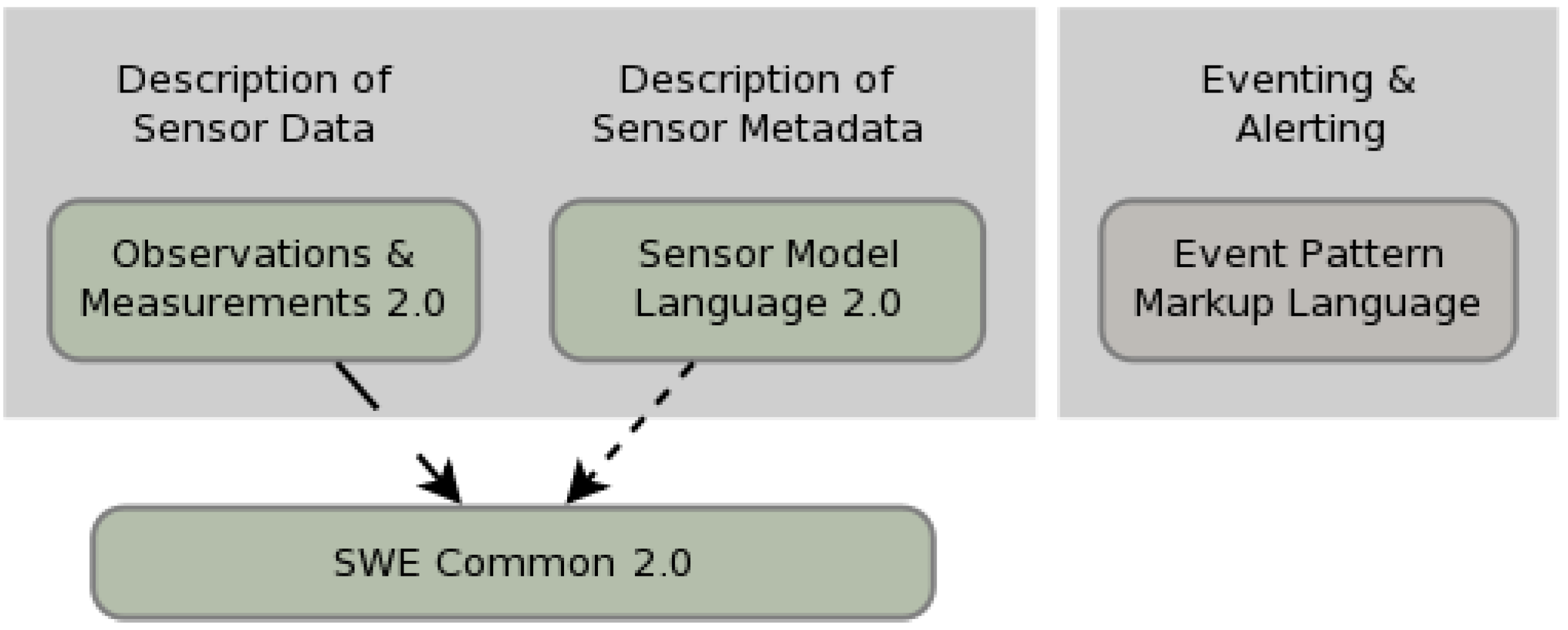
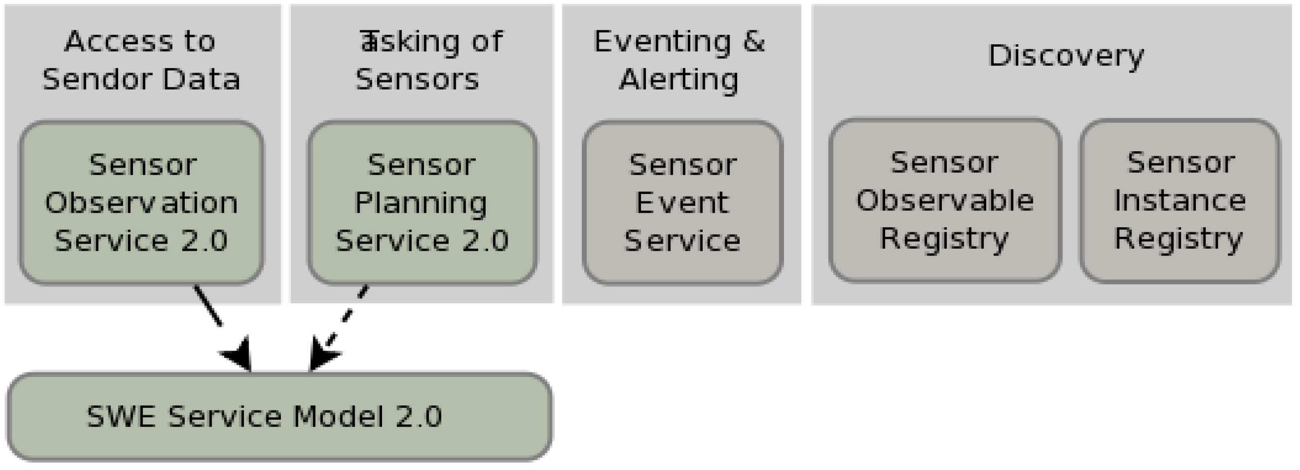
Figure 2 and
Figure 3 show the new generation SWE standards (Version 2.0) which were published in the second half of 2011. Green boxes are specifications approved as standards (or in standardization process), grey boxes are discussion papers and dashed arrows point to dependencies.
SWE Common specifies low level data models for exchanging sensor related data between SWE framework nodes. It defines the representation, nature, structure and encoding of sensor related data [
65]. Observations & Measurements (O&M) defines a conceptual schema for observations, and for features involved in sampling when making observations. These provide models for the exchange of information describing observation acts and their results, both within and between different scientific and technical communities [
66]. SWE services use SensorML as a format for describing their associated sensors [
67]. The model provides information needed for discovery of sensors, location of sensor observations, processing of low-level sensor observations, and listing of configurable sensor properties. A sensor is defined as a process which is capable of observing a phenomenon and returning an observed value. For example, a process can be a measurement procedure conducted by a sensor or the post processing of previously gathered data. Event Pattern Markup Language (EML) defines subscription filters to SWE framework nodes that provide publish/subscribe type services. Currently, the Sensor Event Service (SES) is the first prototype within OGC SWE that supports EML. Both the O&M and SensorML models extend the OGC’s Geographic Markup Language (GML) which is a standard XML encoding for expressing geographical features. This provides the functionality to integrate sensors into Spatial Data Infrastructures (SDI).
Figure 2.
Sensor web enablement (SWE) common.
Figure 2.
Sensor web enablement (SWE) common.
Figure 3.
SWE Service Model.
Figure 3.
SWE Service Model.
SWE Service Model defines packages with data types and operation request and response types for common use across SWE services [
68]. Sensor Observation Service (SOS) provides standardized access to sensor observations and sensor metadata [
69]. The service acts as a mediator between a client and a sensor data archive or a real-time sensor system. The heterogeneous communication protocols and data formats of the associated sensors are hidden by the standardized interface of SOS. SOS defines O&M as its mandatory and default response format for sensor data and recommends the usage of SensorML for sensor metadata exchange. Sensor Planning Service (SPS) is a web service interface that allows clients to submit tasks to sensors for operations such as the configuration of the sampling rate or the steering of a movable sensor platform [
70]. SPS operations derive from the abstract request type defined by SWE Service Model and aggregates operations covering the complete process of controlling and planning sensor tasks.
Sensor Event Service (SES) is a SWE service specification at discussion phase. It provides a push-based access to sensor data as well as functionality for sensor data mining and fusion inside a spatial data structure. SES uses the OASIS WS-Notification (WS-N) standard for the definition of the service operations needed for a publish/subscribe communication. This suite of standards defines operations for subscription handling and notifications (WS-BaseNotification), for the brokering of notifications (WS-BrokeredNotification) and for the use of event channels (WS-Topics). Event channels allow a grouping of notifications with respect to a specific topic, for instance weather forecasts. Instead of defining the filter for forecasts in each consumer’s subscription, a consumer can simply subscribe for all notifications on the weather channel. Consumers may also use filter criteria while subscribing to sensor data. Depending on the filter type used these criteria operate on single observations or on observation streams, potentially aggregating observations into higher-level information (which itself can be regarded as observation data).
Sensor Instance Registry (SIR) provides functionality to collect, manages, transform and transfer sensor metadata through SensorML as well as extended discovery functionality and sensor status information. It is intended to close the gap between the SensorML based SWE world and conventional Spatial Data Infrastructures (SDIs). In the future it is expected that the functionality of the SIR interface will partly be covered by other existing SWE services (e.g., SOS for retrieving sensor status information and the SES for filtering sensor status updates).
Sensor Observable Registry (SOR) is designed in order to support users when dealing with identifiers pointing to phenomenon observed by a sensor (observable) which is very important when searching for sensors. Usually such parameters are expressed within SensorML documents through some kind of identifier (
i.e., URIs).
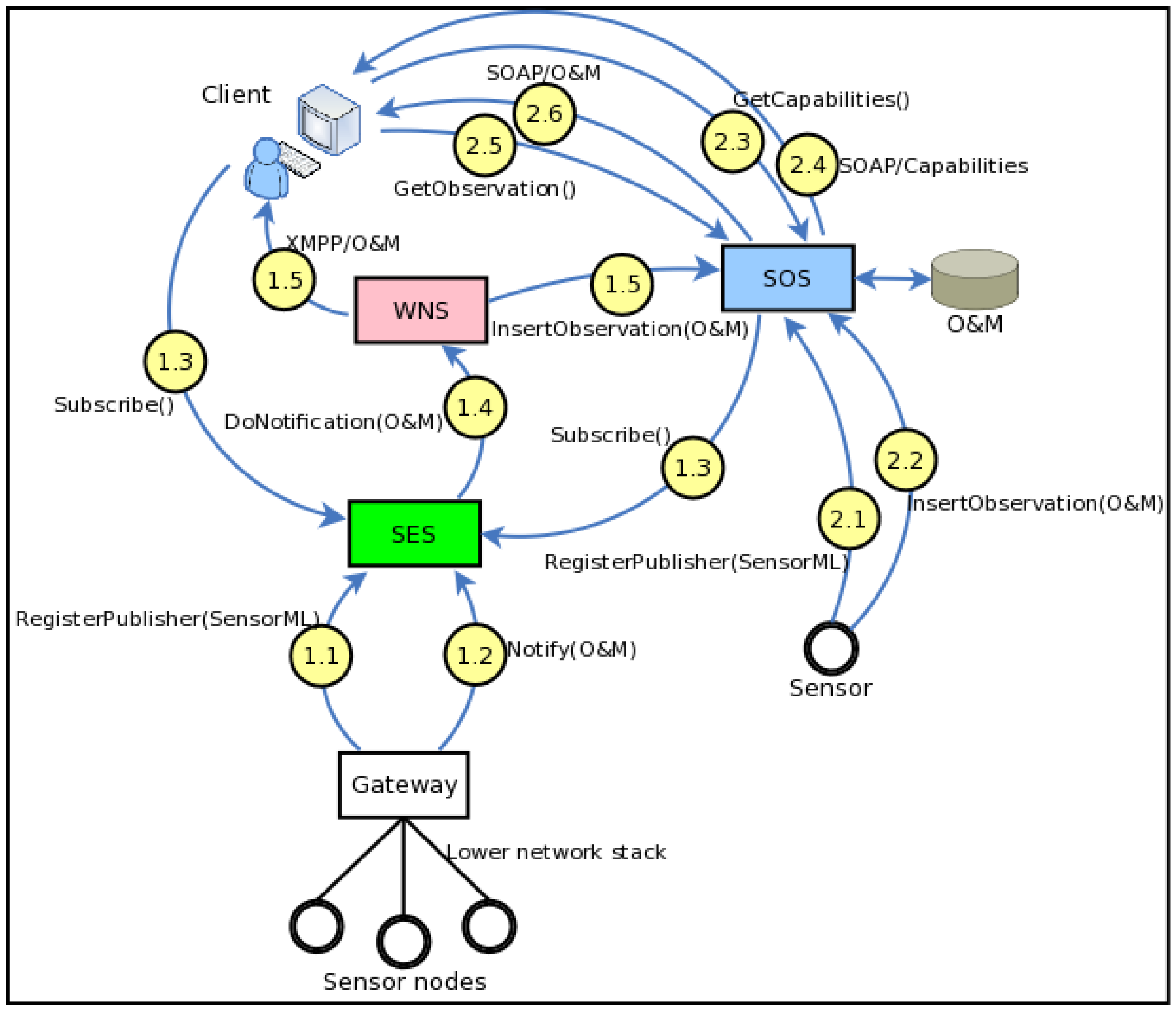
Figure 4 depicts two scenarios where the SWE architecture is in action: sensors without embedded IP stack, and sensors with embedded IP stack. The scenarios have been simplified in order to clarify the basic idea. More details can be found in the standards specifications and the SWE white papers.
SWE is a standard M2M architecture that focuses primarily on the requirements of the scientific community dealing with remote sensor and sensor data management. Certain features of the SWE architecture pose a barrier for its widespread adoption for this purpose. For example, the complexity of the SOAP based SWE service interface specification and other extension specifications (e.g., OASIS WS-Notification, etc.) are one of these barriers. Future versions add a lightweight HTTP GET binding for certain operations with the aim of improving ease of adoption. Another issue is the tight coupling of the information model with GML which binds spatial data infrastructure across all data ubiquitously. While this feature makes it easy to relate sensor data with other spatial-temporal resources (e.g., maps, raster as well as vector data) at the application level, this is not a requirement in all M2M scenarios. However, adaptation of the SWE information model may provide useful solutions within the context of M2M service networks.
Figure 4.
SWE Architecture in action.
Figure 4.
SWE Architecture in action.
Scenario 1—Sensors without Embedded IP Stack
1.1 Multiple sensor nodes connect to a SWE Gateway. Sensor networks that utilize various network topologies and low level communication protocols may be connected to the SWE architecture in this manner. The Gateway layers the sensor network data with Internet and Web protocols and relays it to a SES server. Initially the gateway calls the RegisterPublisher operation to add sensors to the SES. The request includes a SensorML which describes the sensor and its capabilities.
1.2 Sensor data is published to the SES via the Gateway. Notify operation, which contains sensor data in the O&M standard, is used.
1.3 A SOS server and a user application subscribe to sensor data using the Subscribe operation. The requests include the topic and the filtering specifications, as well as the information about the endpoint to which the filtered sensor data should be delivered. The step would probably be preceded by GetCapabilities and DescribeSensor operations which allow the consumers to collect information about the available sensor data that is being brokered by the SES. Note that while the SOS acts as a consumer in this interaction it is in fact a broker of sensor data. In SWE any service, application or process may act as a consumer as long as it provides an endpoint where notifications can be delivered to. Thus, even chaining of information brokers is possible.
1.4 SES forwards the sensor data that conforms to the subscription filters; to the WNS by invoking the DoNotification operation. The request includes the id of the delivery endpoint account.
1.5 WNS delivers the sensor data to the intended consumers. It must be noted that to receive notifications consumers have to be registered to the WNS beforehand. In this scenario the SOS consumer receives the data via HTTP POST while the user application receives it via XMPP.
Scenario 2—Sensors with Embedded IP Stack
2.1 A sensor registers itself to an SOS server by invoking the RegisterSensor operation. The request includes a SensorML document that describes the sensor capabilities. In this scenario the sensor system includes an embedded IP stack that allows it to communicate directly with the SOS server over the Internet.
2.2 The sensor sends streaming observation data to the SOS by invoking its InsertObservation operation. The data is encoded in O&M format and it is persisted on the SOS backend.
2.3 A SWE client invokes the GetCapabilities operation of the SOS. This operation allows clients to retrieve service metadata about a specific service instance.
2.4 SOS responds with the response with an XML encoded document. This document provides clients with service Filter Capabilities which indicate what types of query parameters are supported by the service and Contents Section in the form of Observation Offerings. These are sets of sensor observation groupings that can be queried using the GetObservation operation. Note that the response will not only include metadata that describe observations collected from the sensor mentioned in this scenario but also the observations received from the sensor nodes in the previous scenario.
2.5 Based on the information gained in the previous steps the client requests sensor observations by invoking the GetObservation operation. The request parameters are based on the Filter Capabilities information received in the previous GetCapabilities request. This may be a one-off operation or the client may poll the SOS periodically.
2.6 The response to a GetObservation request is an O&M Observation, an element in the Observation substitution group, or an ObservationCollection. These are historical sensor observations retrieved from the SOS backend.
The SWE Common and O&M which are data models for exchanging heterogeneous sensor data at low and higher levels respectively allow applications and/or servers to structure, encode and transmit data in a self-describing and semantically enabled way. O&M, which is based on Martin Fowler’s Observation & Measurements analysis pattern [
71], is a dynamic model that can adapt smoothly to new requirements without necessarily needing to change implementation or the way objects interact. It is therefore, a particularly interesting solution for the description of device data across different business domains.
One of the key requirements of M2M systems is the ability to fuse, interpret or transform device data into higher level information, required by various M2M applications. A mechanism that enables such on-demand processing, using generic software that utilizes standard process descriptors, simplifies M2M application development and facilitates interoperability. The view-point of the sensor as a process or a chain of processes in the SensorML model with detailed process input, output, parameter, and method descriptions makes it a possible candidate for such a generic process descriptor.
The ongoing work on SensorML 2.0 is planning additional functionalities such as the Sensor Interface Descriptor (SID) extension. SID enables the precise description of a sensor's protocol and interface. This work may be used as a basis to develop generic device drivers carrying protocol definitions of legacy devices which in turn would allow on-the-fly, plug-and-play integration of such non-compliant devices into the standard M2M service network without the need for manual ad-hoc development for each device type [
3].
3.3. ETSI M2M Service Capability Layer
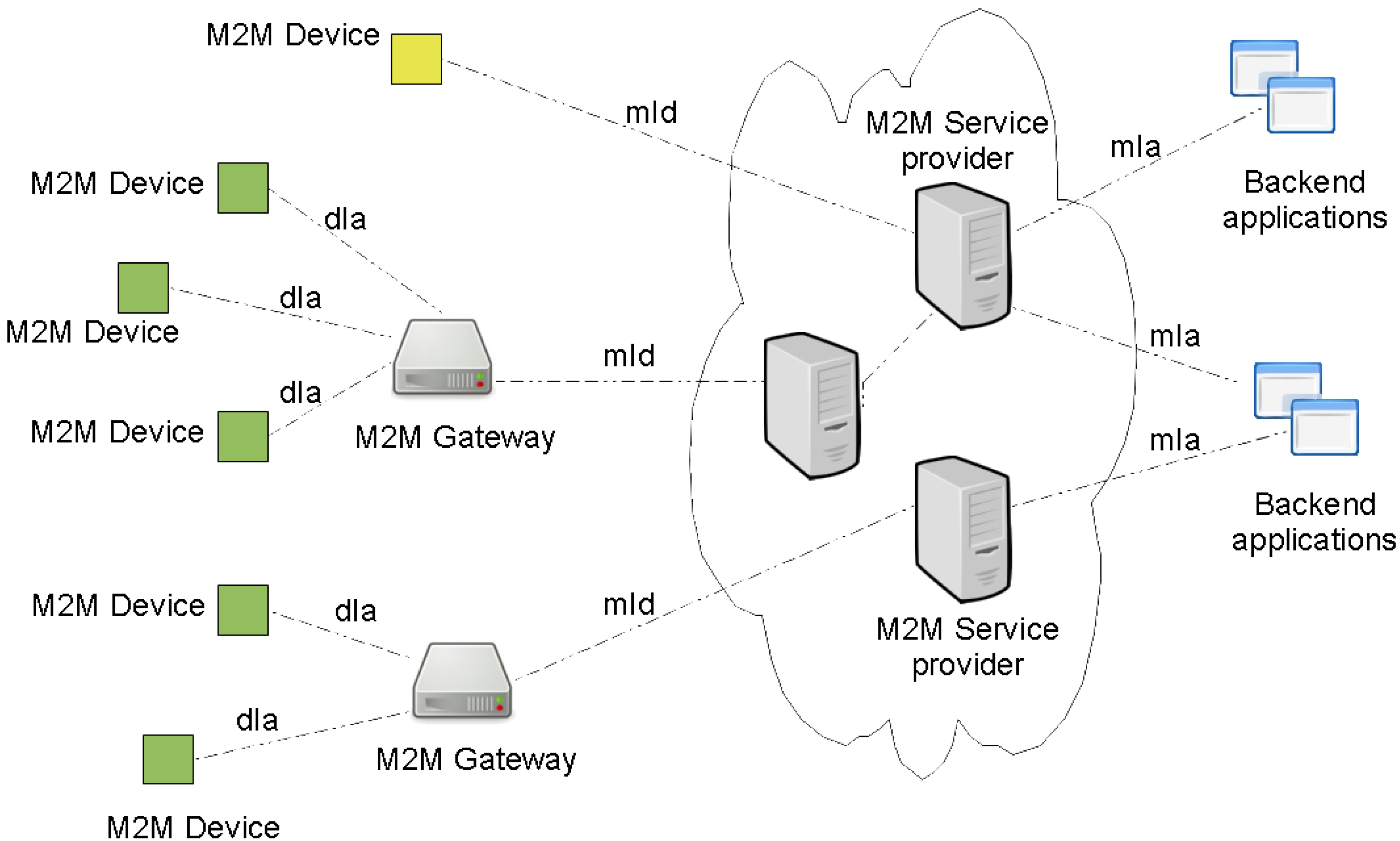
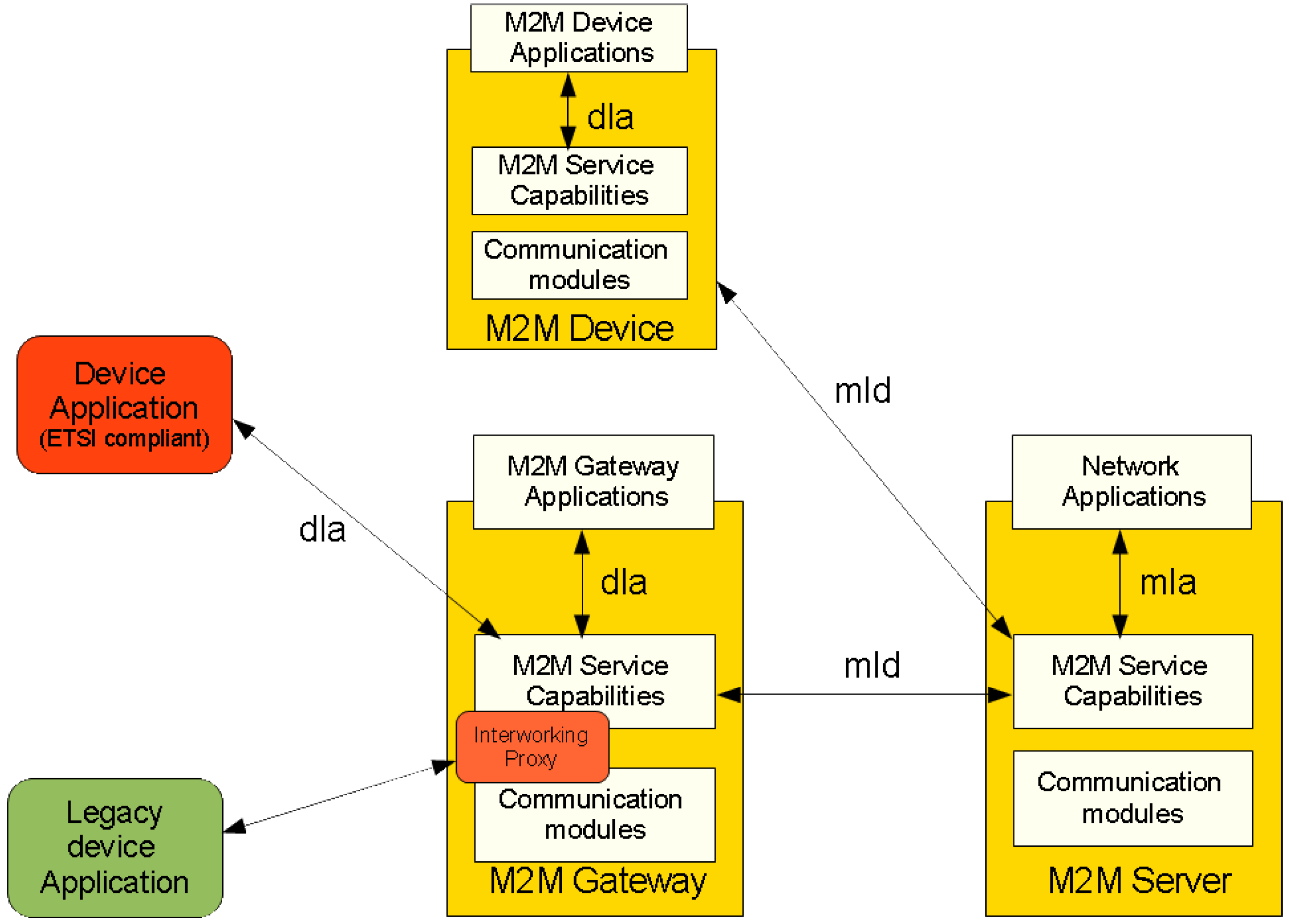
ETSI provides an M2M network architecture specification with a generic set of service capabilities. The idea of the architecture is to provide horizontal service capability layer that can be applied to several vertical M2M application domains with standardized reference points. The ETSI M2M Network is composed of two domains: (1) The Device and Gateway domain with M2M devices and Gateways and (2) the Network domain with core network access, M2M service capabilities, M2M applications and management functions, see
Figure 5 and
Figure 6.
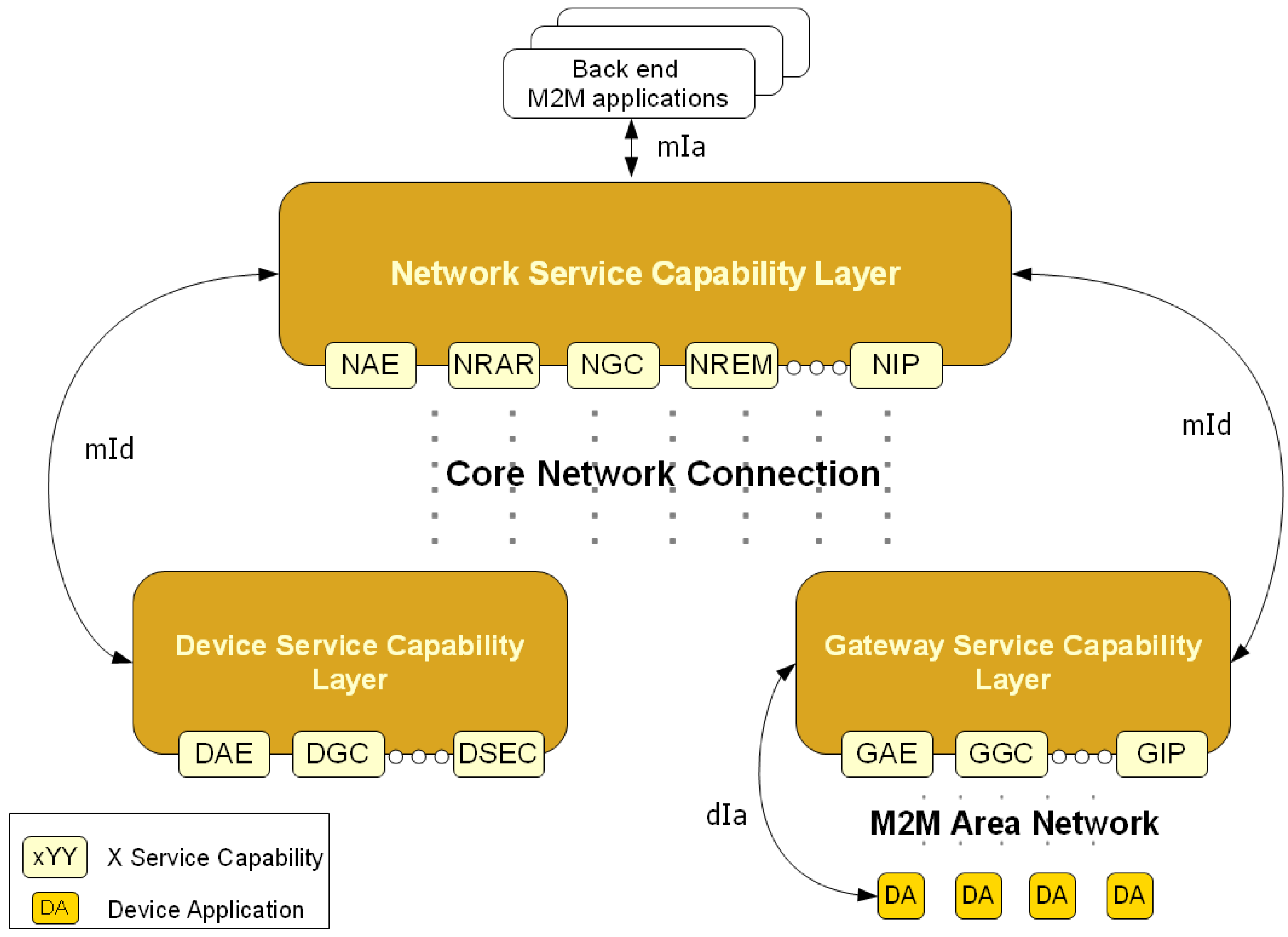
Three different Service Capability Layers are specified: a Device Service Capability Layer, a Gateway Service Capability Layer and a Network Service Capability Layer. Each SCL exposes the services required by the M2M applications residing in the underlying M2M Network. The ETSI adopted a RESTful [
72] architecture style for the M2M Applications and/or M2M SCL information exchange [
18].
Each SCL is comprised of several services groups: Application Enablement Capability (AEC) for providing M2M point of contact for using the M2M applications of the corresponding SCL, Generic Communication Capability (GCC) for interfacing between the different SCL available on a given M2M Network, Reachability, Addressing and Repository Capability (RARC) for managing events relative subscriptions and notifications as well as for handling applications registration data and information storage, Communication Selection Capability (CSC) for network selection and alternative communication service selection after a communication failure, Remote Entity Management Capability (REM) for remote provisioning, Security Capability (SECC), History and Data Retention for archiving data (HDR), and Interworking Proxy (IP) for integrating non ETSI compliant systems.
Figure 5.
M2M system with ETSI M2M standard reference points.
Figure 5.
M2M system with ETSI M2M standard reference points.
Figure 6.
Interfaces of ETSI M2M system.
Figure 6.
Interfaces of ETSI M2M system.
The presented service capabilities are logical groups of functions identified by ETSI, but all of them are not mandatory [
18]. Only the external reference points, dIa, mId and mIa, between the M2M applications and SCLs are mandatory. Where the dIa interfaces devices applications and Gateway or Device Service Capability Layer, the mId interfaces the M2M Gateway or Device Service Capability Layer and the M2M Network Service Capability Layer and the mIa interfaces backend M2M Applications and the M2M Network Service Capability Layer. These interfaces aim to be applicable to a wide range of network technology and application and access independent [
35].
The ETSI M2M architecture indicates that it does not explicitly specify means for integrating legacy devices or other already existing non-ETSI compliant systems, but it presents integration points (Interworking Proxy) on the Gateway and Network Service Capability Layers [
15].
Figure 7 presents the different M2M Service Capability Layers that comprise the ETSI M2M Network as well as the related reference points.
According to the ETSI M2M architecture, an M2M Gateway can act as a proxy for M2M devices available in the same local area network. Once M2M devices applications are registered on a given GSCL, they become available to the registered SCLs and M2M applications if they acquire the appropriate access rights. Ex: Network applications can subscribe to information produced by a sensor (Device application) registered on a reachable GSCL.
Figure 8 explains how this can be done.
We presume that the GSCL is registered to the NSCL and that the Device Application is registered to the GSCL. First the Network application registers to the NSCL (001). Then Network Application Enablement capability checks if the issuer is authorized to be registered and treats the request (002). The registration information is then stored by the Network Reachability, Addressing and Repository Capability. After it Network Application receives a positive answer (003). The Network Application subscribes to the data produced by the desired sensor (Device application) (004). This data can also follow a certain criteria specified by the issue. If the issuer is authorized to subscribe to the given Device Application, the Gateway Reachability, Addressing and Reachability capability treat the request (005). Network application receives a positive response (006). Device application sends information to the Gateway (007). Then Gateway Reachability, Addressing and Repository Capability identify an event that needs to be reported to a subscriber (008). Finally, The GRAR Capability notifies the subscribers (009).
Figure 7.
Architecture of ETSI M2M Service Capabilities.
Figure 7.
Architecture of ETSI M2M Service Capabilities.
Figure 8.
Sequence diagram for a network application subscription to device data.
Figure 8.
Sequence diagram for a network application subscription to device data.
3.4. Autonomic M2M Services
Autonomic computing has been inspired from biological systems including both centralized and decentralized approaches, which have been proposed to enable autonomic behavior in computer systems. The centralized approach focuses on the role of human nervous system as a controller to regulate and maintain the other systems in body [
73]. Decentralized approaches take inspiration from local and global behavior of biological cell and ant colony networks [
74]. Another area focuses on developing self-managed large scale distributed systems and databases. One such project is Oceano [
75], a project of IBM providing a pilot prototype of a scalable, manageable infrastructure for a large scale utility power plant. OceanStore [
76], a project of University of California Berkeley describes a global persistent data store for scaling billion of users. IBM’s SMART [
77] offers a solution to reduce complexity and improve quality of service through the advancement of self-managing capabilities. Similarly, Microsoft’s AutoAdmin [
78] makes database system self-tuning and self-administering by enabling them to track the usage of their system and gracefully adapt to application requirements. Agent architecture has been frequently used to develop infrastructures supporting autonomic behavior based on a decentralized approach. Unity [
79] makes use of this approach to achieve goal-driven self-assembly, self-healing and real-time self-optimization. Similarly, Autonomia [
80] is a University of Arizona project providing the application developers with all the tools required to specify the appropriate control and management schemes to maintain any quality of service requirements.
Component based frameworks have been suggested for enabling autonomic behavior in systems. The Accord framework [
81] facilitates development and management of autonomic applications in grid computing environments. It provides self-configuration by separating component behavior from component interaction. Selfware [
82] models the managed environment as a component based software architecture which provides means to configure and reconfigure the environment and implements control loops which link probes to reconfiguration services and implement autonomic behaviors. A number of frameworks make use of techniques such as artificial intelligence (AI) and control theory. In [
83] an AI planning framework based on the predicate model has been presented. It achieves user defined abstract goals by taking into account current context and security policies. Another area focuses on modifying control theory technique [
84] and presents a framework to address resource management problem. A mathematical model is used for forecasting over a limited time horizon. Service Oriented Architecture has been also used to design architecture with autonomic behavior. In [
85], autonomic web services implement the monitoring, analysis, planning and execution life cycle. The autonomic web service uses log file provided by a defective functional service to diagnose the problem and consults the policy database to apply appropriate recovery action. Infrastructures have been proposed to inject autonomic behavior in legacy and non-autonomic system, where design and code information is unavailable [
86]. Some of the identified frameworks make use of layered architecture [
87], case based reasoning (CBR) [
88], and a rule driven approach [
89] to enable automaticity in existing systems.
Different techniques can be used to achieve the capabilities described in each of the four major self-* properties. There are more system specific techniques to achieve self-configuration such as hot swapping [
90] and data clustering [
91], and techniques that make use of more generic approaches such as machine learning, ABLE [
92] and case-based reasoning [
93]. Many applications that require continuous performance improvement and resource management make use of control theory approach demonstrated in the Lotus Notes application [
94], learning based self-optimization techniques such as LEO [
95], and active learning based approach [
96] based on building statistical predictive models. Self-healing is the property that involves problem detection, diagnosis and repair. CBR [
93] performs problem detection in the analysis phase, finds a solution in planning phase and performs problem repair in execution phase. Hybrid approach [
97] to create a survivability model provides more robust survivability services. Active probing and Bayesian network [
98] is a problem diagnosis technique that allows probes to be selected and sent on demand. The heartbeat failure detection algorithm [
99] enables detecting problem when the monitor experiences a delay in receiving of message. Another technique to detect problems in distributed systems is to use tools like Pip [
100] that expose structural errors and performance problems by comparing actual system behavior and expected system behavior. Performance Query Systems (PQS) [
101] can be used to enable user space monitoring of servers. Component level rebooting is a technique that recovers from defects, without disturbing the rest of the application as shown in Microreboot [
102]. Another safe technique to quickly recover programs from deterministic and non-deterministic bugs is demonstrated in Rx [
103]. It rolls back the program to a recent checkpoint upon a software failure, and then re-executes the program in a modified environment. Some notable techniques that enable systems to enable self-protection make use of component models such as Jade [
104] and self-certifying alerts as demonstrated in Vigilante [
105].
