Article

Enhancing CuFP Library with Self-Alignment Technique

by
Fahimeh Hajizadeh
1,*,
Tarek Ould-Bachir
2,* and
Jean Pierre David
1,*
1
Department of Electrical Engineering, Polytechnique Montreal, Montreal, QC H3T 1J4, Canada
2
MOTCE Laboratory, Department of Computer Engineering, Polytechnique Montréal, Montreal, QC H3T 1J4, Canada
*
Authors to whom correspondence should be addressed.
Computers 2025, 14(4), 118; https://doi.org/10.3390/computers14040118
Submission received: 31 January 2025 / Revised: 6 March 2025 / Accepted: 19 March 2025 / Published: 24 March 2025

Abstract

:
High-Level Synthesis (HLS) tools have transformed FPGA development by streamlining digital design and enhancing efficiency. Meanwhile, advancements in semiconductor technology now support the integration of hundreds of floating-point units on a single chip, enabling more resource-intensive computations. CuFP, an HLS library, facilitates the creation of customized floating-point operators with configurable exponent and mantissa bit widths, providing greater flexibility and resource efficiency. This paper introduces the integration of the self-alignment technique (SAT) into the CuFP library, extending its capability for customized addition-related floating-point operations with enhanced precision and resource utilization. Our findings demonstrate that incorporating SAT into CuFP enables the efficient FPGA deployment of complex floating-point operators, achieving significant reductions in computational latency and improved resource efficiency. Specifically, for a vector size of 64, CuFPSAF reduces execution cycles by 29.4% compared to CuFP and by 81.5% compared to vendor IP while maintaining the same DSP utilization as CuFP and reducing it by 59.7% compared to vendor IP. These results highlight the efficiency of SAT in FPGA-based floating-point computations.

1. Introduction

Advances in semiconductor technology have enabled the development of highly dense devices capable of hosting tens to hundreds of floating-point operators on a single chip. Modern field-programmable gate arrays (FPGAs) exemplify this trend, offering substantial computational resources for applications requiring high performance and flexibility [1,2]. However, leveraging these devices for computationally intensive tasks, such as floating-point dot product operations, remains challenging due to the trade-offs between precision, hardware area, and latency.
In [3], the authors introduced the CuFP library, a customizable floating-point library compatible with High-Level Synthesis (HLS) tools. CuFP allows developers to define floating-point formats with tailored precision by specifying the bit widths of the exponent and mantissa, enabling application-specific optimizations. While this customization significantly enhances flexibility in balancing precision and resource usage, it can also introduce challenges in computational performance for key operations, such as the dot product (DP) [4]. In large-scale systems and high-precision configurations, increasing the bit widths of the exponent and mantissa often extends the critical path in arithmetic operations, leading to longer delays and reduced throughput. To address these challenges, hardware implementations are typically optimized to minimize critical path delays. To some extent, leveraging techniques such as pipelining, loop unrolling, and resource partitioning can help mitigate these issues while preserving the precision benefits provided by CuFP. However, there are scenarios where these traditional optimization techniques fall short.
To address this limitation, we propose an enhanced the CuFP library (CuFPSAF) that integrates a Self-Alignment Format (SAF) [5] into the CuFP library to create a scalable, resource-efficient floating-point arithmetic framework for FPGA-based computing. SAF achieves significant reductions in latency and hardware area by keeping the alignment of the mantissa and exponent and removing unnecessary packing/unpacking stages outside of the critical path. This approach ensures that alignment operations do not directly impact the execution time of arithmetic computations. However, it has not been designed for seamless integration into an HLS framework. By bridging the gap between CuFP’s configurability and SAF’s efficiency, CuFPSAF provides a novel solution that significantly reduces the latency and hardware area required for floating-point operations across various precision formats, including simple, double, and quadruple precision. Integrating CuFPSAF into other projects is simple, as users can easily add a header file, ensuring smooth integration and a user-friendly implementation. Its open-source and platform-independent design fosters transparency, simplifies debugging, and ensures high performance https://github.com/FahimeHajizadeh/Custom-Float-HLS (accessed on 31 January 2025).
In this work, we also present some well-known operators, such as vector summation, dot product, and matrix-vector multiplication, based on the proposed CuFPSAF library and evaluate their performance in terms of latency and area occupation. The results demonstrate that CuFPSAF enables more efficient implementation of complex floating-point operations, particularly when applied to computationally intensive tasks. Additionally, we highlight the benefits of a fused-path approach to enhance performance while maintaining accuracy.
The remainder of this paper is organized as follows: Section 2 presents an overview of floating-point numbers, the CuFP library, and some acceleration techniques. Section 3 details the CuFPSAF design and development flow. Section 4 provides a comprehensive evaluation of the proposed approach. Section 5 disscuses more about the proposed design. Finally, Section 6 concludes the paper and outlines potential avenues for future research.

2. Background

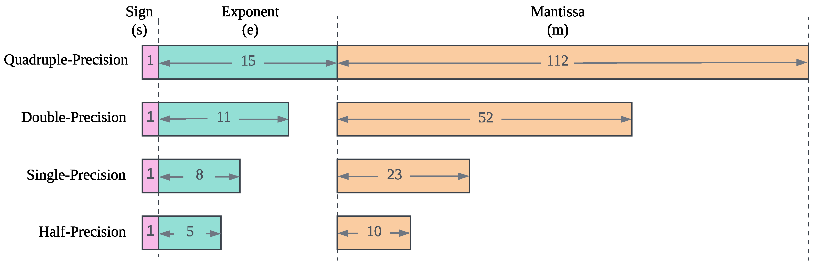
2.1. Floating-Point Format

Floating-point arithmetic is a fundamental aspect of numerical computation, enabling efficient representation and manipulation of a wide range of real numbers. The IEEE-754 standard is a globally recognized and extensively utilized framework for representing floating-point numbers [6]. This standard defines a format for expressing real numbers in a way that balances precision and dynamic range, enabling accurate and efficient computation in scientific, engineering, and data-intensive applications. Floating-point numbers under this standard are expressed in the form:
x = ( 1 ) s · m · 2 e
where s is the sign bit, m is the normalized mantissa m [ 1 , 2 ) , and e is the exponent, typically stored in a biased form. This format allows efficient representation of a wide range of numbers, accommodating both very large and extremely small values. As shown in Figure 1, the IEEE-754 standard defines several precision levels to accommodate various computational needs: half-precision (16 bits), single-precision (32 bits), double-precision (64 bits), and quadruple-precision (128 bits).

2.2. Challenges in Floating-Point Operations

Floating-point arithmetic plays a crucial role in many computational applications. However, performing floating-point operations, especially in high-performance contexts, presents several challenges. One of the primary concerns is the computational complexity and resource demands associated with these operations. Floating-point calculations often involve multiple steps, such as exponentiation and mantissa normalization, which can be resource-intensive. This complexity is further amplified in hardware implementations, particularly in systems like FPGAs, where high precision requirements can significantly increase the area, power consumption, and processing time. For applications such as dot products or matrix multiplications, these operations can become a bottleneck, limiting the overall performance and efficiency of the system.
Moreover, standard floating-point formats, which are defined by IEEE 754, are not always well suited for custom hardware applications. While IEEE 754 provides a standardized approach to floating-point representation, it is designed for general-purpose use and may not meet the specific needs of certain applications [7]. For example, standard formats, such as 32-bit or 64-bit floating-point formats, can be inefficient when precision is required only within a specific range. These formats may waste hardware resources, leading to suboptimal utilization of the available logic, increased latency, and unnecessary power consumption. This inefficiency can be particularly problematic in high-performance or real-time systems, as it introduces unnecessary overhead that limits the potential for optimization [8,9]. Therefore, there is a growing need for customizable floating-point representations that offer greater flexibility in balancing precision, resource utilization, and computational efficiency tailored to the unique requirements of the target application [10,11,12,13,14,15]. In addition, high performance in FPGA-based floating-point computing can be achieved by eliminating unnecessary packing/unpacking stages as well as removing the intermediate stages [3,16,17,18]. Template HLS (THLS) [13] is an HLS library that provides a high-level approach to implementing custom floating-point operations using C++ templates. This framework enables the selection of exponent and fraction bit widths at compile time. Although THLS delivers a distinctive solution for both simulation and synthesis, its scope is largely limited to fundamental operations. TrueFlaot [12] is another work that is combined with the open-source HLS framework Bambu [19]. Moreover, the authors in [15] propose a parameterized, fused multi-term floating-point dot product architecture specifically optimized for high-level synthesis. While this architecture showcases significant advancements, it does not support heterogeneous formats, which reduces its versatility and applicability in scenarios requiring mixed precision computations.

2.3. Role of High-Level Synthesis (HLS)

High-Level Synthesis (HLS) is a powerful tool that bridges the gap between software design and hardware implementation. It allows developers to describe hardware behavior using high-level programming languages such as C, C++, or OpenCL rather than dealing with low-level hardware description languages like VHDL or Verilog [20]. This abstraction simplifies the design process and significantly accelerates development cycles, enabling more complex systems to be implemented with greater ease.
The primary benefit of HLS is its ability to translate high-level code into hardware descriptions that can be synthesized into FPGA designs [21,22]. By using high-level languages, developers can focus more on the algorithmic aspects of their designs, leaving the hardware optimization to the HLS toolchain. HLS tools analyze the code and generate hardware circuits that best match the desired functionality while also optimizing for performance, area, and power consumption. This streamlines the process of creating custom hardware accelerators tailored to specific computational tasks, such as floating-point operations.

2.4. Overview of the CuFP Library

The CuFP library, presented in [3], is a specialized collection of floating-point operators designed to address the limitations of standard IEEE 754 formats, offering increased flexibility for high-performance and resource-constrained applications. The core idea behind CuFP is to enable the customization of floating-point formats, allowing the user to adjust key parameters such as the mantissa and exponent widths. This ability to tailor floating-point precision is crucial for applications that require specific trade-offs between computational precision and hardware resource utilization.
CuFP provides a set of high-level functions that can be synthesized onto hardware platforms, such as FPGAs, using HLS tools. These functions are optimized to ensure efficient hardware utilization and fast execution times, especially in computationally intensive operations such as dot products, matrix-vector multiplications, and other numerical computations. By offering fine-grained control over the floating-point representation, CuFP allows for more efficient use of FPGA resources and reduces latency while maintaining adequate precision for the given application.
A distinguishing feature of CuFP is its flexibility in balancing precision and resource consumption. The library supports dynamic configurations where the user can define the number of bits used for the mantissa and exponent, making it adaptable to various levels of precision requirements. This customizability ensures that CuFP can meet the needs of diverse applications, from embedded systems to high-performance computing. In the context of real-time simulations, CuFP is particularly beneficial as it enables the acceleration of floating-point operations, allowing complex calculations to be performed with minimal delay. The library’s ability to seamlessly interact with HLS tools further facilitates its integration into FPGA-based systems, making it an ideal choice for applications in areas such as signal processing, power systems simulation, and machine learning, where both speed and precision are crucial. However, despite these advantages, CuFP faces challenges when applied to large-scale systems. As the system size and computational complexity increase, resource utilization on the FPGA becomes a critical bottleneck. To address these challenges, we propose an enhancement to the CuFP library by integrating a Self-Alignment Technique (SAT).

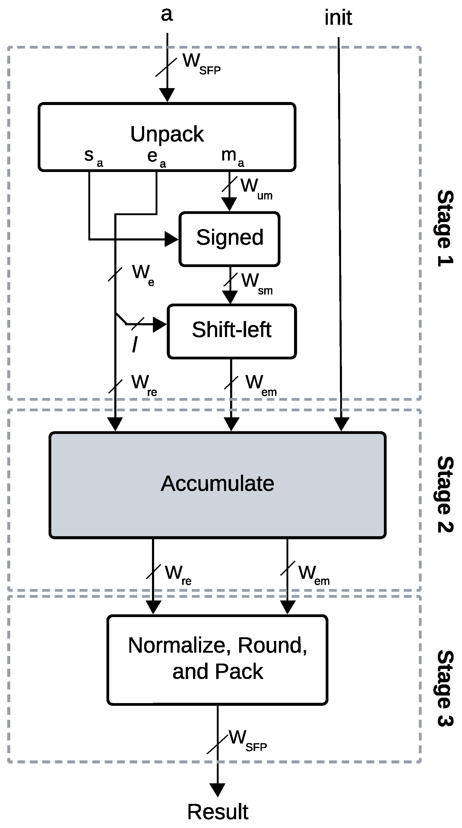
2.5. Self-Alignment Technique (SAT)

The Self-Alignment Technique (SAT) is an innovative approach designed to optimize floating-point operations, particularly in the context of high-performance hardware implementations. It addresses the critical challenge of single-cycle floating-point accumulation [23]. In Reference [5], a cost-effective method for implementing high-accuracy floating-point operators on FPGAs using the self-alignment technique is presented, enabling the achievement of high clock frequencies.

2.5.1. SAT-Based Addition

SAT-Based Addition represents an approach to optimizing arithmetic operations. Initially introduced to address challenges in single-cycle floating-point accumulation, the SAT has demonstrated its efficacy in reducing critical path delays in accumulation processes [23,24]. The technique minimizes interactions between the incoming addend and the running sum by aligning the incoming mantissa relative to a common boundary defined by the exponents of the summands. This strategic alignment ensures that fine-grained shifts of the mantissa occur outside the critical path, significantly improving the efficiency of the accumulation loop. Therefore, SAT effectively decouples the computational overhead of mantissa adjustments from the primary addition process, enabling faster and more reliable arithmetic operations.
The main stages of an SAT-based accumulator are detailed in [5]. As illustrated in Figure 2, the input a, represented as a standard floating-point number, is first unpacked. Unpacking involves decomposing into its constituent parts: sign ( s a ), exponent ( e a ), and mantissa ( m a ). Then, the mantissa is extended ( W e m ) with respect to the least significant bits of the exponent of a. In the next processing stage, accumulation takes place over consecutive cycles. The result in stage 3 must be packed. This stage includes converting to the standard floating-point format after normalization and rounding.

2.5.2. Self-Alignment Format (SAF)

The Self-Aligned Format (SAF) [5], which is based on the self-alignment technique [23], is designed to enhance the precision and performance of floating-point operations. The SAF represents a floating-point number x f p that is represented in S A F ( l , w , b ) as a pair consisting of an integral reduced exponent and an integral extended mantissa, denoted as ( e , m ) . In this notation, l is the number of least significant bits discarded from the standard floating-point exponent; w is the width of the extended mantissa; and b is a bias used to adjust the dynamic range. The number x f p is formulated as follows:
x f p = m · 2 2 l ( e b )
In this format, the mantissa is first extended by one bit, and the sign is incorporated into the mantissa. Specifically, for negative numbers, the two’s complement representation is applied accordingly. Following this, a portion of the exponent, with a length of l bits, is transferred to the mantissa, which extends it by 2 l 1 bits. This results in a reduced exponent and an extended mantissa.
Figure 3 shows the extended mantissa. To ensure high accuracy during subsequent operations, particularly in the adder tree and accumulator, log 2 ( N ) bits are added to the most significant part of the extended mantissa. Additionally, g guard bits are appended to the least significant part of the mantissa. This process preserves the required precision for the forthcoming computations. In summary, the SAF enhances the mantissa by incorporating part of the exponent and adding extra bits to retain precision. Consequently, the exponent becomes reduced.

3. Implementation Methodology

The SAF format, previously detailed in Section 2.5.2, is seamlessly integrated into the CuFP library to enhance its functionality. The CuFPSAF is implemented using a templated C++ design, allowing for flexibility and scalability by supporting customizable word lengths and exponent sizes. This templated approach ensures that the library can be easily adapted to meet a wide range of application requirements while maintaining high performance and precision. This approach offers several advantages, including allowing users to customize the SAF parameters (l, w, b) based on their specific requirements. Furthermore, integrating SAF into the CuFP library enables users to efficiently handle large-scale systems, leveraging the flexibility of the framework. This adaptability proves particularly valuable for developing algorithms optimized for either high efficiency or low latency, depending on the user’s needs.
The choice of coding style plays a critical role in determining the efficiency and performance of the RTL generated by the HLS tool. While object-oriented programming (OOP) in C++ tends to introduce some overhead, it provides significant benefits in terms of code organization, extensibility, and maintainability. In contrast, procedural programming, often seen in C-style implementations, can be more efficient but might sacrifice readability and flexibility. In this paper, we strike a balance by using a templated class approach and function-based operations. This allows us to retain the efficiency of procedural coding while benefiting from the modularity and clarity offered by OOP. Therefore, the proposed templated class for CuFPSAF enables flexibility in customizing the floating-point format according to the specific needs of the application. This approach allows users to adjust parameters such as word length, exponent size, and bias, making the library adaptable to a wide range of use cases.

3.1. CuFPSAF Data Type

The CuFPSAF is a templated class designed to represent and manipulate numbers in the SAF format. It accepts four template parameters:
  • WM: specifies the bit width of the mantissa.
  • WE: specifies the bit width of the exponent.
  • l: indicates the number of bits dropped in the exponent.
  • b: represents the bias value, calculated based on the selected SAF format.
The CuFPSAF class includes three primary member variables: m (mantissa), e (exponent), and lsh (left shift of original mantissa). These variables collectively define the SAF representation and enable efficient computational operations. Listing 1 presents the definition of the CuFPSAF class, omitting the implementation details of the member functions to maintain readability. This modular design facilitates flexible customization and efficient adaptation of the SAF format to specific application requirements.
Listing 1. The body of CustomFloat template class.
Computers 14 00118 i001

3.2. Primary Operations

3.2.1. CuFPSAF Addition

The CuFPSAF addition operation leverages the self-alignment technique to efficiently compute the sum of two floating-point numbers, x and y. Algorithm 1 shows the CuFPSAF addition algorithm. Each floating-point number is defined by its exponent and mantissa, x ( e x , m x , l s h x ) and y ( e y , m y , l s h y ) , respectively. The algorithm begins by determining the input with the larger exponent and storing it as k ( e k , m k , l s h k ) . Hence, the larger exponent is considered as e k , and it serves as the base alignment reference ( e z ). Using this reference, the alignment shifts for the mantissas are calculated as q x = e k e x and q y = e k e y . These shift amounts align the mantissas to a common exponent e z , enabling their addition in the same numerical range. The mantissas are then adjusted and summed as
m z = ( m x ( q x l ) ) + ( m y ( q y l ) )
where ≫ represents a right shift operation to account for the alignment. Finally, the algorithm returns the result z ( e z , m z , l s h z ) , representing the sum in the CuFPSAF format.
This technique simplifies alignment by introducing the 2 l scaling factor, which reduces hardware complexity. The mantissas are aligned and added efficiently, avoiding costly re-normalization steps.
Algorithm 1: CuFPSAF Addition (inspired from [5])
1 Parameters:  W M , W E , l , b
2 Inputs:  x ( e x , m x , l s h x ) , y ( e y , m y , l s h y )
3 Outputs:  z ( e z , m z , l s h z )
4 Local Variables:  k ( e k , m k , l s h k )
5  k max ( x , y )
6 ;
7 // Compare x and y based on e x and e y
8  e z e k
9  l s h z l s h k
10  q x e k e x
11  q y e k e y
12  m z ( m x ( q x l ) ) + ( m y ( q y l ) )
13 Return z

3.2.2. CuFPSAF Multiplication

The CuFPSAF multiplication operation utilizes the self-alignment technique to efficiently compute the product of two floating-point numbers, x and y. Algorithm 2 shows the CuFPSAF multiplication algorithm. The algorithm starts by computing the combined exponent e by concatenating the exponents e x and e y along with their respective left shifts, then adjusting it by subtracting a constant bias B derived from the exponent width W E and precision width l. This step ensures that the exponents are appropriately scaled for multiplication. The final exponent e z and left shift l s h z values are then extracted from the combined exponent e. For the mantissas, the algorithm applies right shifts to m x and m y based on their corresponding left shift factors l s h x and l s h y . These adjusted mantissas are then multiplied together, and the mantissa result is stored in m z . Finally, the algorithm returns the result z ( e z , m z , l s h z ) , which represents the product of x and y in the CuFPSAF format.    
Algorithm 2: CuFPSAF Multiplication
1 Parameters:  W M , W E , l , b
2 Inputs:  x ( e x , m x , l s h x ) , y ( e y , m y , l s h y )
3 Outputs:  z ( e z , m z , l s h z )
4 Local Variables: e
5 Constant:  B 2 W E + l 1 1
6  e c o n c a t ( e x , l s h x ) + c o n c a t ( e y , l s h y ) B ;
7  e z e . r a n g e ( W E + l 1 , l )
8  l s h z e . r a n g e ( l 1 , 0 )
9  m z ( m x l s h x ) × ( m y l s h y )
10 Return z

3.3. Vector-Based Operations

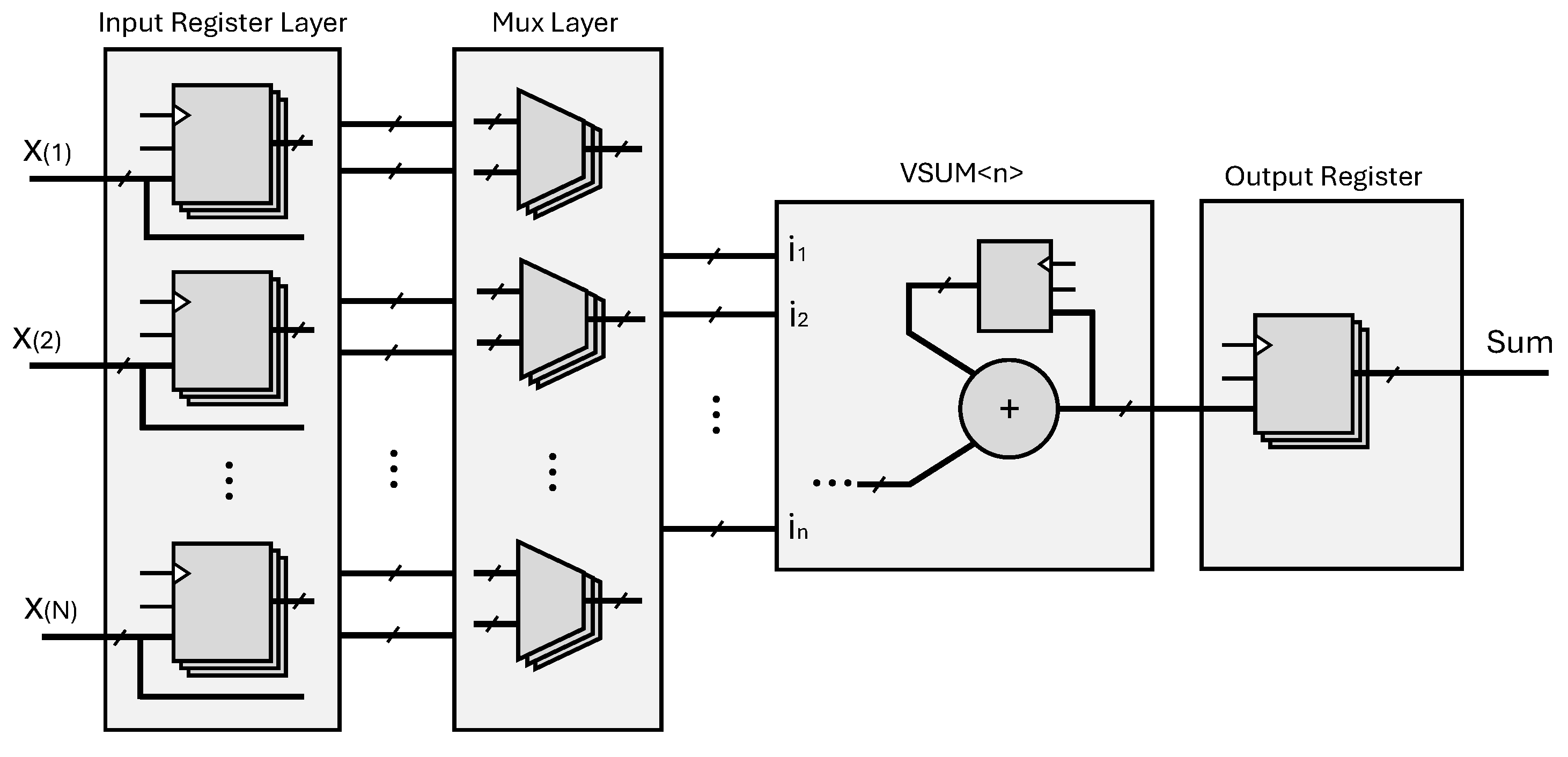
3.3.1. CuFPSAF Vector Summation

Vector summation (vsum) is an essential operation in computational mathematics and data analysis, where the elements of a vector are aggregated into a single scalar value. For a vector x = [ x 1 , x 2 , , x N ] containing N elements, the summation is expressed as
i = 1 N x i = x 1 + x 2 + + x N
The templated function vsum is designed to accumulate N elements from an array of custom floating-point numbers represented by the CuFPSAF data type.
The vsum function implementation is expressed in Algorithm 3, which takes a vector of the CuFPSAF object with N elements and returns the result in a scalar CuFPSAF format. The function begins by identifying the index of the element with the maximum exponent in the input array x[N] using the max_index function.
This function performs a binary search to find the element with the largest exponent, operating with a time complexity of O ( l o g N ) . As this step is often scheduled to execute in a single clock cycle, it incurs minimal latency. Once the maximum exponent is identified, the corresponding e and lsh values of the result are directly assigned from the maximum element found. Next, the mantissas of all elements in the input vector are aligned with the maximum exponent by performing a right-shift operation based on their exponent difference. The aligned mantissas are stored in the temporary array vm, which is fully partitioned to leverage parallelism. Finally, the summation of all aligned mantissas in vm is performed using a tree-based vector addition for integers, implemented as vsum_int. This function employs a hierarchical structure that pre-allocates adders for each pair of input elements and iteratively sums intermediate results until a single integer is obtained. With a time complexity of O ( l o g N ) , vsum_int is critical to the overall performance of the vsum function, as its latency largely dictates the final latency.
Algorithm 3: CuFPSAF Vector Summation
1 Parameters:  W M , W E , l , b , N
2 Inputs:  x = { x 1 , x 2 , , x N } { ( e x 1 , m x 1 , l s h x 1 ) , ( e x 2 , m x 2 , l s h x 2 ) , , ( e x N , m x N , l s h x N ) }
3 Outputs:  z ( e z , m z , l s h z )
4 Local Variables:  v m [ N ]
5 Constant:  B 2 W E + l 1 1
6  i d x max max _ index ( e x 1 , e x 2 , , e x N )
7  k z [ i d x m a x ]
8  e z e k
9  l s h z l s h k
10  v m { m x 1 ( ( e k e x 1 ) l ) , m x 2 ( ( e k e x 2 ) l ) , , m x N ( ( e k e x N ) l ) }
11  m z vsum _ int ( v m )
12 Return z;

3.3.2. CuFPSAF Dot Product

The dot product (dp) unit is a critical component for numerous computational tasks, particularly in applications involving machine learning, signal processing, and numerical computations. It computes the sum of the products of corresponding elements from two input vectors. Mathematically, for two vectors x = [ x 1 , x 2 , , x N ] and y = [ y 1 , y 2 , , y N ] , the dot product is expressed as
D P = i = 1 N x i · y i
The templated function dp implements the dot product operation for two input vectors, x[N] and y[N], consisting of custom floating-point numbers represented by the CuFPSAF data type. A pseudo-code for this operation is provided in Listing 2. The function begins by calculating the element-wise product of corresponding elements from the two input vectors using the mul function (line 12). These products are stored in an intermediate vector, which is fully partitioned to eliminate read and write access conflicts and ensure that all operations can proceed without memory bottlenecks (lines 6 and 7). Afterward, the intermediate products are accumulated using the vsum function (line 15). Finally, the result is returned as a single CuFPSAF object.
Listing 2. A pseudo-code of SAFCuFP dot product operation.
Computers 14 00118 i002
This implementation, referred to as the Latency-Constrained (LC) approach, offers a significant advantage in its ability to process a new input series every clock cycle. This capability greatly enhances throughput and computational power, making it especially well suited for latency-sensitive and real-time applications that demand rapid, responsive computations with minimal delay. However, the main trade-off of this approach is that resource utilization increases linearly with the size of the input vectors, which may pose challenges for hardware with limited resources.
However, many modern applications are designed to process vast amounts of data, often dealing with vectors of large size. These large-scale datasets are increasingly common in fields like machine learning, scientific computing, and big data analytics. In such contexts, operations like the dot product are essential, playing a critical role in tasks such as similarity measurement, optimization, and data transformation. Efficiently processing large vectors is critical for achieving accurate and high-performance results, making the optimization of dot product operations a key area of focus in high-performance computing. Therefore, for very large-scale systems, particularly those with large-sized vectors, the LC approach faces limitations. As the vector size increases, the total resource requirements grow significantly. In FPGA-based applications, this increase in resource usage can become a major issue, as the hardware resources may become overburdened, leading to potential inefficiencies and bottlenecks.
To address these challenges, we propose an alternative approach called the Resource-Constrained (RC) approach, which is designed for scenarios where the size of the input vectors is large, and system resources need to be managed efficiently. While this approach is described in the context of the dot product, its methodology can be applied to other computationally intensive operations. A parameter known as the n is introduced to specify how the input vectors are divided into N/n smaller sub-vectors with n elements, enabling sequential processing of partial computations. The results for each sub-vector are progressively accumulated to obtain the final output, as shown in Equation (5).
D P = k = 1 N n i = 1 n x i ( k ) y i ( k )
This approach strikes a balance between resource utilization and performance by limiting hardware requirements, as it reduces the resources by processing smaller segments of the vector at a time, rather than the entire vector simultaneously. Consequently, it is particularly well suited for scenarios where FPGA resources are limited, and efficient computation of large vectors is essential.
Figure 4 compares the two approaches for dot product design. In the LC approach, shown in Figure 4a, the computation follows Equation (4), where the entire input vector is processed simultaneously to achieve minimal latency. On the other hand, the RC approach, depicted in Figure 4b, divides the input vectors into smaller sub-vectors and allocates the arithmetic logic required for only n input size to reduce hardware resource usage. The partial results coming from the reduced arithmetic unit are progressively accumulated. This approach offers flexibility to address varying design constraints and optimization goals.
Figure 5 shows the scheduling of allocated arithmetic units for the dot product operation under the two distinct approaches. In the LC approach (Figure 5a), all multiplications (mul) are executed in parallel, followed by the vector summation (vsum), which minimizes latency at the cost of higher resource usage. Conversely, the RC approach (Figure 5b) divides the vector into smaller segments based on a user-defined parameter (n). Each segment undergoes partial dot product computation (dp), and the intermediate results are progressively accumulated (ACC) over multiple cycles.
For a vector of size N, the LC approach requires N multipliers and a single vector summation unit for size N, with the total latency calculated as
total ( Latency Constrained ) = mul + vsum
In contrast, in the RC approach, the vector is divided into N / n sub-vectors, enabling resource reuse. The total latency for this approach is given by:
total ( Resource Constrained ) = ( N / n ) + ( dp 1 ) + ACC
The following pseudo-code, Listing 3, represents managing the dot product operation in both approaches. A wrapper function named dp_wrapper is used to handle both approaches using appropriate directives and operations. The choice of approach is determined at compile-time through preprocessor directives (C_LATENCY or C_RESOURCE). In the LC approach (lines 12–18), the entire input vectors are processed in parallel to achieve minimal latency and maximum throughput. The input vectors are fully partitioned to allow simultaneous access to all elements, and the operation is pipelined with an initiation interval (II) of 1, enabling new inputs to be processed every clock cycle.
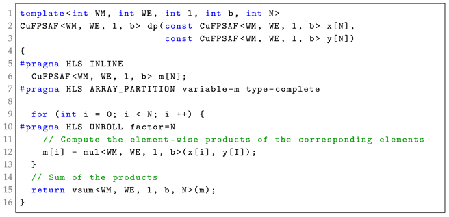
Listing 3. A pseudo-code of CuFPSAF dot product operation, considering two different approaches: Latency-Constrained and Resource-Constrained.
Computers 14 00118 i003
In the RC approach (lines 19–31), the algorithm utilizes two helper functions: dp_fold and sum. The dp_fold function (lines 4–8) acts as a wrapper for the dp operation, processing sub-vectors of size n. To conserve resources, only one instance of dp_fold is allowed, enforced by a directive that restricts instantiation. In dp_wrapper, the input vectors are divided into sub-vectors of size n, which are processed iteratively. The dot product for each sub-vector is computed using dp_fold, and the results are accumulated in a loop. The loop is pipelined without a fixed initiation interval, allowing the HLS tool to optimize the interval for resource efficiency.

3.3.3. CuFPSAF Matrix-Vector Multiplication

The CuFPSAF matrix-vector multiplication (mvm) is a critical component in many high-performance computing applications, particularly those involving linear algebra and machine learning. Conceptually, mvm involves computing the dot product between each row of the matrix and the input vector, with each result contributing to an element of the output vector, as follows:
x 11 x 12 x 1 j x 21 x 22 x 2 j x i 1 x i 2 x i j y 1 y 2 y j = x 11 y 1 + x 12 y 2 + + x 1 j y j x 21 y 1 + x 22 y 2 + + x 2 j y j x i 1 y 1 + x i 2 y 2 + + x i j y j
Since mvm requires a large number of additions and multiplications, its direct implementation would demand significant parallel resources, which may not be feasible in FPGA-based designs. To address this, CuFPSAF implements mvm using the introduced dp computation unit while leveraging the RC approach to balance scalability and performance. The mvm function is implemented using a series of dp units, where each instance processes a row of the matrix and the vector elements. Listing 4 illustrates how the mvm function is implemented using the dp computation unit. The number of dp instances can be adjusted in line 12, where it can take an arbitrary value. Increasing this limit enhances parallelism, reduces latency, but also increases resource consumption, requiring a trade-off between performance and hardware efficiency.
Listing 4. A pseudo-code of CuFPSAF matrix-vector multiplication, considering RC approach.
Computers 14 00118 i004

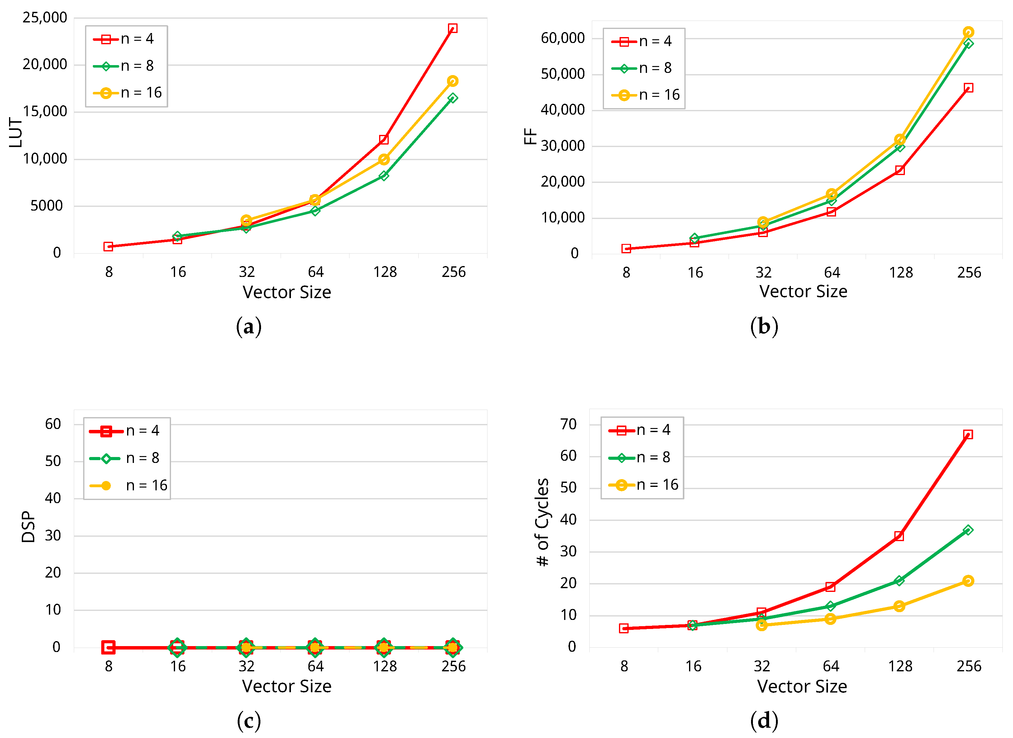
4. Experimental Results

This section presents the experimental results of implementing the proposed CuFPSAF on the Alveo U280 FPGA using Vitis HLS 2023.2. The target device chosen is the xcu280-fsvh2892-2L-e. It should be noted that, for all circuits discussed in this paper, input and output registers are employed to guarantee precise signal handling and readiness for subsequent processing stages. As an example, a pipeline circuit with three levels includes two computational stages, with registers placed at both the input and output for proper synchronization and data flow. Moreover, to ensure a fair comparison across all implementations, we configured the CuFPSAF, CuFP, and Vendor IP to operate within the same numerical precision, specifically in single-precision floating-point format. We set w m = 64 , l = 5 (where 2 l = 32 ), and b = 23 + 127 = 150 to align with the standard single-precision floating-point representation, where the mantissa consists of 23 bits and the exponent bias is 127. These parameter choices ensure that all implementations are evaluated under equivalent precision constraints, allowing for a meaningful comparison of accuracy, resource utilization, and performance.

Error Evaluation

In this study, we employ the 2-norm relative error ( R E 2 n o r m ) as the primary metric to quantify the discrepancy between computed and reference outputs. This metric is particularly suited for numerical analysis, as it captures the overall deviation while normalizing the error relative to the magnitude of the reference output.
The R E 2 n o r m is mathematically expressed as
R E 2 n o r m = out ref out com 2 out ref 2
Here, out ref denotes the reference output, and out com represents the computed output. The 2-norm ( · 2 ) of a vector is defined as the square root of the sum of the squares of its components, effectively measuring its Euclidean magnitude. The numerator out ref out com 2 represents the magnitude of the error between the computed and reference outputs, while the denominator out ref 2 scales this error relative to the reference output’s magnitude.
This approach ensures that the error metric is dimensionless and normalized, making it suitable for comparing results across different scales and conditions. Smaller RE2-norm values indicate higher accuracy, whereas larger values signify greater deviation from the reference output.
Table 1 presents the 2-norm relative error ( R E 2 - n o r m ) evaluation for three floating-point variants: Vendor IP (standard single-precision floating-point), CuFP [3], and CuFPSAF, based on the same set of 100,000 randomly generated numbers. The results focus on Sum and Mul, as these are the two primary operations reported in CuFP, allowing for a direct and fair comparison. Moreover, Sum and Mul are fundamental to complex operations like vsum and dp, and their sensitivity to errors straightforwardly impacts the accuracy of more complex operations. The results show that the errors for the CuFP and CuFPSAF variants are comparable to the Vendor IP, with slightly lower values in most cases.
The comparison in Table 2 highlights the resource utilization and performance of three variants—Vendor IP, CuFP [3], and CuFPSAF—across different vector sizes for the vsum operation. Vendor IP exhibits the highest resource utilization, with a significant number of DSPs, LUTs, and FFs used, but its latency, measured in cycles, is relatively larger. In contrast, CuFP eliminates DSP usage entirely, showing moderate resource usage, though its latency is higher than CuFPSAF. CuFPSAF demonstrates the most efficient performance, achieving the lowest latency and LUT utilization; however, its FF usage surpasses that of CuFP. Notably, CuFPSAF demonstrates a less pronounced increase in FF usage as vector sizes grow, highlighting its scalability and efficiency for larger workloads. This balance between latency, LUTs, and FF scalability underscores CuFPSAF’s suitability for lightweight, high-performance designs.
Table 3 presents the resource utilization and performance of the dp operation for Vendor IP, Fused Vector FP [15], CuFP [3], and CuFPSAF across various vector sizes. Vendor IP consumes the most resources overall, with a steep increase in DSP, LUT, and FF utilization as the vector size grows. Fused Vector FP, while offering improved latency compared to Vendor IP, requires significantly higher LUT and FF resources, particularly for larger vector sizes, which may limit its scalability. CuFP, on the other hand, demonstrates moderate resource usage and consistent latency across all vector sizes, making it a predictable and efficient choice. CuFPSAF achieves the shortest latency among all variants and maintains competitive resource utilization, particularly for DSP and LUT usage. However, CuFPSAF’s FF utilization increases more significantly than CuFP’s, especially for larger vector sizes. This trend highlights the trade-offs involved in achieving low latency and high computational efficiency.
Figure 6 presents the impact of varying the dividing factor (n) and different vector sizes on resource utilization (LUT, FF, and DSP) and the number of cycles for the CuFPSAF vector summation operation. For a fixed vector size, increasing n results in reduced latency. For instance, when comparing the results for n = 4 to n = 8 , we observe a reduction in latency across all vector sizes. For smaller vector sizes, such as 8 and 16, the latency remains relatively stable. However, as the vector size increases, the latency reduction becomes more pronounced when moving from n = 4 to n = 8 . This trend continues as we increase n further to 16, with latency continuing to decrease for larger vectors. LUT utilization does not scale inversely with n due to the additional control logic overhead required for managing the RC approach. As n increases, while fewer arithmetic units are needed, the operand scheduling complexity increases, requiring additional control logic. This results in a less pronounced reduction in LUT utilization compared to other resources.
For different vector sizes, the latency increases as the vector size grows, which is a natural consequence of handling larger data. However, it is important to note that the increase in latency with vector size is less pronounced for higher n -values. This behavior demonstrates the efficiency of larger dividing factors in managing larger datasets, as they distribute the computational load more evenly and better handle increased workloads. Additionally, for a fixed vector size (N), selecting an appropriate n is crucial; it should neither be too large nor too small.
Figure 7 illustrates the impact of varying the dividing factor ( n ) and different vector sizes on resource utilization (LUT, FF, and DSP) and the number of cycles for the CuFPSAF dot product. As the dividing factor increases ( n = 4 , n = 8 , n = 16 ), there is a significant rise in resource usage, particularly for LUTs and FFs. This is expected because larger n introduces greater parallelism, which in turn requires more hardware resources. Similarly, DSP usage scales predictably, doubling with each increase in n —from 8 for n = 4 to 16 for n = 8 and 32 for n = 16 .
For a fixed vector size, increasing n consistently reduces the number of cycles. However, this improvement in latency comes at the expense of higher resource utilization. When considering different vector sizes, a clear trend emerges: the number of cycles increases with larger vectors for the same n . Nevertheless, the increase in latency with vector size is less pronounced for higher n -values, underscoring the efficiency of larger dividing factors in handling more extensive workloads. This behavior indicates that larger dividing factors are better equipped to process larger workloads efficiently as they distribute the computational effort more effectively.
By mitigating the impact of vector size on latency, higher n -values allow for better scalability. For applications with larger vectors, this characteristic becomes particularly advantageous, as it ensures that the latency overhead remains manageable even as the computational demands grow. This highlights the potential of larger dividing factors for optimizing performance in systems designed to handle high data throughput or large-scale processing tasks.
In comparison, the LC approach, as shown in Table 2 and Table 3, achieves minimal latency by performing all computations in parallel. However, this comes at the cost of significantly higher FPGA resource usage, particularly in terms of LUTs and FFs, making it less suitable for resource-constrained applications. The RC approach, as demonstrated in Figure 6 and Figure 7, processes the small sub-vectors and consequently uses fewer resources, making it more appropriate for scenarios where hardware resources are limited. This trade-off between latency and resource utilization is a critical consideration when selecting the appropriate approach for a given application.
To evaluate CuFPSAF at a larger scale, we compare its performance against CuFP and Vendor IP in matrix-vector multiplication (mvm). We consider matrices of sizes 4 × 4 , 8 × 8 , 16 × 16 , and 32 × 32 , with vector sizes of 4, 8, 16, and 32, respectively, meaning that n takes values of 4, 8, 16, and 32. Figure 8 presents LUT, FF, and DSP utilization, along with latency in clock cycles. LUT consumption, shown in Figure 8a, indicates that CuFPSAF requires approximately 100K LUTs, whereas CuFP and Vendor IP exceed 250K and 300K LUTs, respectively, for a 32 × 32 matrix size. This highlights CuFPSAF’s lower LUT footprint.
Figure 8b illustrates FF utilization, where the CuFPSAF and CuFP exhibit comparable consumption, but CuFPSAF achieves lower FF usage as matrix dimensions increase. The most significant improvement is seen in DSP utilization, as shown in Figure 8c in logarithmic scale. The CuFPSAF requires between 32 and 256 DSPs, whereas CuFP ranges from 32 to 2048 DSPs, and Vendor IP from 72 to 5056 DSPs. This demonstrates that the RC approach in CuFPSAF provides a significantly more resource-efficient solution for large-scale computations. For larger matrix dimensions, maintaining the same performance trends with CuFP and Vendor IP would become increasingly resource-intensive, necessitating alternative resource management strategies for scalability. In terms of latency, Figure 8d shows that CuFPSAF achieves execution times ranging from five to thirteen cycles, whereas CuFP operates between six and seven cycles. While CuFP offers slightly lower latency, this advantage comes at the cost of significantly higher resource consumption, making it unsustainable as computations scale. In contrast, the CuFPSAF balances performance and resource efficiency, making it more suitable for large-scale FPGA-based floating-point operations.

5. Discussion

By integrating SAF into CuFP in a templated, configurable manner, CuFPSAF significantly enhances performance and computational efficiency in FPGA-based systems while providing a streamlined HLS framework. This integration also ensures flexibility for varying precision requirements and hardware constraints. The experimental results highlight several key improvements introduced by this approach, including reductions in latency, resource utilization, and error rates, as well as improved scalability across various vector sizes and operational complexities.
The CuFPSAF demonstrates superior performance when compared to both the CuFP library [3], Fused Vector FP [15], and vendor-provided IP cores. Specifically, SAF’s ability to streamline alignment operations by reducing the dependency on packing and unpacking stages leads to lower hardware area usage and faster computation times. This is particularly evident in the dot product and vector summation operations, where CuFPSAF achieves the lowest latency and maintains competitive accuracy relative to standard floating-point implementations.
The experimental results also reveal a clear trade-off between latency and resource usage in CuFPSAF designs. For example, while the LC approach achieves minimal latency by executing all operations in parallel, it demands a higher number of hardware resources. In contrast, the RC approach utilizes a dividing factor (n) to process smaller sub-vectors sequentially, which substantially reduces LUT and DSP utilization. However, the increased number of pipeline stages introduced by this method leads to higher FF utilization, as additional registers are inserted to pass the intermediate signals to the next stages. Moreover, the results indicate that the RC method generally requires fewer LUTs compared to the LC method. However, despite using a fixed number of computation units, the LUT usage still increases as N grows. This is due to the need for scheduling and managing sub-vectors of the input data. As N increases, the complexity of the data path also grows, requiring additional control logic to efficiently route and sequence the sub-vectors for computation. This expanded data path demands more LUTs for multiplexing, selection, and scheduling, contributing to the observed increase in resource utilization, as depicted in Figure 9. This behavior is related to the tool’s handling of the increased complexity and its need to generate additional control logic to manage the growing data path. The trade-off between the LC and RC approaches enables the CuFPSAF framework to cater to a wide range of use cases, from real-time systems requiring high throughput to resource-limited applications where efficiency is paramount.
Another critical observation is the scalability of CuFPSAF for larger vector sizes. By effectively distributing the computational workload, CuFPSAF minimizes the latency impact of increasing data sizes. This scalability is enhanced by the flexibility of the dividing factor, which allows the user to balance performance and resource utilization according to system constraints. The results for large vectors confirm that CuFPSAF can efficiently handle computationally intensive tasks without overburdening the hardware.
Despite these advancements, some challenges remain. The increased usage of FFs in CuFPSAF highlights an area for potential optimization. Future research could explore alternative implementation strategies to mitigate this trade-off while preserving the performance benefits of SAF. Additionally, the CuFPSAF framework could be further extended to support more complex operations, such as matrix multiplications and tensor computations, to broaden its applicability in fields like machine learning and scientific simulations.

6. Conclusions

This study demonstrates that integrating the SAF into the CuFP library significantly enhances the efficiency and performance of floating-point operations on FPGA platforms. The CuFPSAF framework achieves notable improvements in latency, hardware resource utilization, and scalability while maintaining high computational accuracy. Specifically, for a vector size of 64, CuFPSAF reduces execution cycles by 29.4% compared to CuFP and by 81.5% compared to vendor IP while utilizing 59.7% fewer DSPs than vendor IP. These advantages make CuFPSAF particularly well suited for high-performance applications, such as real-time simulations, signal processing, and machine learning, where both speed and precision are critical.
The flexibility of the CuFPSAF framework, enabled by its templated design, allows for seamless customization to meet diverse application requirements. This adaptability, combined with the ability to balance latency and resource usage through dividing factors, ensures the framework’s relevance in a variety of computational scenarios.
Future work will focus on extending the capabilities of the CuFPSAF library to support more complex computational tasks and exploring optimization techniques to further reduce resource usage. Additionally, investigating the integration of CuFPSAF with other high-performance computing platforms could provide valuable insights into its broader applicability.

Author Contributions

Conceptualization, F.H., T.O.-B. and J.P.D.; methodology, F.H., T.O.-B. and J.P.D.; software, F.H.; validation, F.H.; formal analysis, F.H. and T.O.-B.; investigation, F.H. and T.O.-B.; resources, F.H.; data curation, F.H.; writing—original draft preparation, F.H. and T.O.-B.; writing—review and editing, F.H., T.O.-B. and J.P.D.; visualization, F.H.; supervision, T.O.-B. and J.P.D. All authors have read and agreed to the published version of the manuscript.

Funding

This research was funded in part by the NSERC Discovery Grants program. The grant numbers are RGPIN-2021-03935 and RGPIN-2019-05166.

Data Availability Statement

The original data presented in the study is openly available on GitHub at https://github.com/FahimeHajizadeh/Custom-Float-HLS accessed on 31 January 2025.

Conflicts of Interest

The authors declare no conflicts of interest.

References

  1. Xie, K.; Lu, Q.; Jiang, H.; Wang, H. Accurate Sum and Dot Product with New Instruction for High-Precision Computing on ARMv8 Processor. Mathematics 2025, 13, 270. [Google Scholar] [CrossRef]
  2. Xilinx. UG1399: Vitis High-Level Synthesis User Guide; Xilinx: San Jose, CA, USA, 2023. [Google Scholar]
  3. Hajizadeh, F.; Ould-Bachir, T.; David, J.P. CuFP: An HLS Library for Customized Floating-Point Operators. Electronics 2024, 13, 2838. [Google Scholar] [CrossRef]
  4. Sohn, J.; Swartzlander, E.E. Improved Architectures for a Floating-Point Fused Dot Product Unit. In Proceedings of the 2013 IEEE 21st Symposium on Computer Arithmetic, Austin, TX, USA, 7–10 April 2013; pp. 41–48. [Google Scholar]
  5. Ould-Bachir, T.; David, J.P. Self-Alignment Schemes for the Implementation of Addition-Related Floating-Point Operators. Acm Trans. Reconfigurable Technol. Syst. 2013, 6, 1–21. [Google Scholar] [CrossRef]
  6. Std 754-2008; IEEE Standard for Floating-Point Arithmetic. IEEE: New York, NY, USA,, 2008; pp. 1–70.
  7. Jamro, E.; Dąbrowska-Boruch, A.; Russek, P.; Wielgosz, M.; Wiatr, K. Novel architecture for floating point accumulator with cancelation error detection. Bull. Pol. Acad. Sci. Tech. Sci. 2023, 66, 579–587. [Google Scholar] [CrossRef]
  8. Perera, A.; Nilsen, R.; Haugan, T.; Ljokelsoy, K. A Design Method of an Embedded Real-Time Simulator for Electric Drives using Low-Cost System-on-Chip Platform. In Proceedings of the PCIM Europe Digital Days 2021; International Exhibition and Conference for Power Electronics, Intelligent Motion, Renewable Energy and Energy Management, Virtual Event, 3–7 May 2021; pp. 1–8. [Google Scholar]
  9. Zamiri, E.; Sanchez, A.; Yushkova, M.; Martínez-García, M.S.; de Castro, A. Comparison of Different Design Alternatives for Hardware-in-the-Loop of Power Converters. Electronics 2021, 10, 926. [Google Scholar] [CrossRef]
  10. Sanchez, A.; Todorovich, E.; De Castro, A. Exploring the Limits of Floating-Point Resolution for Hardware-In-the-Loop Implemented with FPGAs. Electronics 2018, 7, 219. [Google Scholar] [CrossRef]
  11. Martínez-García, M.S.; de Castro, A.; Sanchez, A.; Garrido, J. Analysis of Resolution in Feedback Signals for Hardware-in-the-Loop Models of Power Converters. Electronics 2019, 8, 1527. [Google Scholar] [CrossRef]
  12. Fiorito, M.; Curzel, S.; Ferrandi, F. TrueFloat: A Templatized Arithmetic Library for HLS Floating-Point Operators. In Proceedings of the Embedded Computer Systems: Architectures, Modeling, and Simulation, Samos, Greece, 2–6 July 2023; Silvano, C., Pilato, C., Reichenbach, M., Eds.; pp. 486–493. [Google Scholar]
  13. Thomas, D.B. Templatised Soft Floating-Point for High-Level Synthesis. In Proceedings of the IEEE Annual International Symposium on Field-Programmable Custom Computing Machines (FCCM), San Diego, CA, USA, 28 April–1 May 2019; pp. 227–235. [Google Scholar]
  14. Gao, J.; Shen, J.; Zhang, Y.; Ji, W.; Huang, H. Precision-Aware Iterative Algorithms Based on Group-Shared Exponents of Floating-Point Numbers. arXiv 2024, arXiv:cs.DC/2411.04686. [Google Scholar]
  15. Filippas, D.; Nicopoulos, C.; Dimitrakopoulos, G. Templatized Fused Vector Floating-Point Dot Product for High-Level Synthesis. J. Low Power Electron. Appl. 2022, 12, 56. [Google Scholar] [CrossRef]
  16. de Dinechin, F.; Pasca, B. Designing Custom Arithmetic Data Paths with FloPoCo. IEEE Des. Test Comput. 2011, 28, 18–27. [Google Scholar] [CrossRef]
  17. Wang, X.; Leeser, M. VFloat: A Variable Precision Fixed- and Floating-Point Library for Reconfigurable Hardware. ACM Trans. Reconfigurable Technol. Syst. 2010, 3, 1–34. [Google Scholar]
  18. Swartzlander, E.E.; Saleh, H.H. FFT Implementation with Fused Floating-Point Operations. IEEE Trans. Comput. 2012, 61, 284–288. [Google Scholar]
  19. Ferrandi, F.; Castellana, V.G.; Curzel, S.; Fezzardi, P.; Fiorito, M.; Lattuada, M.; Minutoli, M.; Pilato, C.; Tumeo, A. Invited: Bambu: An Open-Source Research Framework for the High-Level Synthesis of Complex Applications. In Proceedings of the ACM/IEEE Design Automation Conference (DAC), San Francisco, CA, USA, 5–9 December 2021; pp. 1327–1330. [Google Scholar]
  20. Uguen, Y.; Dinechin, F.D.; Lezaud, V.; Derrien, S. Application-Specific Arithmetic in High-Level Synthesis Tools. ACM Trans. Archit. Code Optim. 2020, 17, 1–23. [Google Scholar]
  21. Nane, R.; Sima, V.M.; Pilato, C.; Choi, J.; Fort, B.; Canis, A.; Chen, Y.T.; Hsiao, H.; Brown, S.; Ferrandi, F.; et al. A Survey and Evaluation of FPGA High-Level Synthesis Tools. IEEE Trans. Comput. Aided Des. Integr. Circuits Syst. 2016, 35, 1591–1604. [Google Scholar]
  22. Lahti, S.; Rintala, M.; Hämäläinen, T.D. Leveraging Modern C++ in High-Level Synthesis. IEEE Trans. Comput. Aided Des. Integr. Circuits Syst. 2023, 42, 1123–1132. [Google Scholar]
  23. Luo, Z.; Martonosi, M. Accelerating pipelined integer and floating-point accumulations in configurable hardware with delayed addition techniques. IEEE Trans. Comput. 2000, 49, 208–218. [Google Scholar] [CrossRef]
  24. Vangal, S.; Hoskote, Y.; Borkar, N.; Alvandpour, A. A 6.2-GFlops Floating-Point Multiply-Accumulator With Conditional Normalization. IEEE J. Solid-State Circuits 2006, 41, 2314–2323. [Google Scholar] [CrossRef]
Figure 1. Several precision levels of IEEE-754 standard.
Computers 14 00118 g001
Figure 2. Main stages of a SAT-based accumulator [5].
Computers 14 00118 g002
Figure 3. Extended mantissa composition in SAF [5].
Computers 14 00118 g003
Figure 4. Dot product design: (a) Latency-Constrained approach; (b) Resource-Constrained approach. The grey line stands for register level.
Computers 14 00118 g004
Figure 5. Schedule viewer: (a) Latency-Constrained approach; (b) Resource-Constrained approach. Arrows indicate the data dependencies between operations.
Computers 14 00118 g005
Figure 6. Comparing the resource utilization of vsum operation for different n (4, 8, 16); (a) LUT Utilization; (b) FF Utilization; (c) DSP Utilization; (d) Number of clock cycles.
Computers 14 00118 g006
Figure 7. Comparing the resource utilization of dp operation for different n (4, 8, 16); (a) LUT utilization; (b) FF utilization; (c) DSP utilization; (d) number of clock cycles.
Computers 14 00118 g007
Figure 8. Comparing the resource utilization of mvm operation for different matrix and vector dimensions; (a) LUT Utilization; (b) FF Utilization; (c) DSP Utilization (Logarithmic scale); (d) Number of clock cycles. The x-axis represents the matrix and vector dimensions, where, for example, “ 4 × 4 , 4” denotes a 4 × 4 matrix multiplied by a 4 × 1 vector.
Computers 14 00118 g008
Figure 9. Input operand scheduling for vsum operation with the RC approach.
Computers 14 00118 g009
Table 1. Error evaluation of CuFP (8, 23), vendor IP (single-precision floating point), and CuFPSAF, based on the same set of 100,000 random numbers.
OperationVariant RE 2 norm (%)
SumVendor IP2.02 × 10 6
CuFP [3]2.68 × 10 6
CuFPSAF2.63 × 10 6
MulVendor IP6.03 × 10 6
CuFP [3]6.35 × 10 6
CuFPSAF6.31 × 10 6
Table 2. Comparing the resource utilization of vsum with different vector sizes for CuFP (8, 23), vendor IP (single-precision floating point), and CuFPSAF at 200 MHz clock frequency.
VariantVector SizeInterval# of CyclesResource Utilization
DSPLUTFF
Vendor IP81121415641887
161163033244007
321206268448247
6412412615,36416,727
CuFP [3]81502010722
1616036621424
3216070323891
6417015,3876999
CuFPSAF81309901197
1614016592640
3214036446046
64150707513,757
Table 3. Comparing the resource utilization of dp with different vector sizes for CuFP (8, 23), vendor IP (single-precision floating point), and CuFPSAF at 200 MHz clock frequency.
VariantVector SizeInterval# of CyclesResource Utilization
DSPLUTFF
Vendor IP81153822043175
161197846046583
3212315810,02813,399
6412731820,30027,031
Fused Vector
FP [15]
8181661602409
16193212,2545290
321136426,09410,409
6411912851,76124,977
CuFP [3]8161623301515
16173242192929
32176481515731
641712816,63413,796
CuFPSAF8151639892030
16153283533975
32156416,2497871
641512828,20814,859
Disclaimer/Publisher’s Note: The statements, opinions and data contained in all publications are solely those of the individual author(s) and contributor(s) and not of MDPI and/or the editor(s). MDPI and/or the editor(s) disclaim responsibility for any injury to people or property resulting from any ideas, methods, instructions or products referred to in the content.

