Article

Release Planning Patterns for the Automotive Domain

1
Institute of Software Engineering, University of Stuttgart, 70569 Stuttgart, Germany
2
Software Engineering Decision Support Laboratory, University of Calgary, Calgary, AB T2N 1N4, Canada
*
Author to whom correspondence should be addressed.
Computers 2022, 11(6), 89; https://doi.org/10.3390/computers11060089
Submission received: 6 April 2022 / Revised: 25 May 2022 / Accepted: 27 May 2022 / Published: 30 May 2022
(This article belongs to the Special Issue Feature Paper in Computers)

Abstract

:
Context: Today’s vehicle development is focusing more and more on handling the vast amount of software and hardware inside the vehicle. The resulting planning and development of the software especially confronts original equipment manufacturers (OEMs) with major challenges that have to be mastered. This makes effective and efficient release planning that provides the development scope in the required quality even more important. In addition, the OEMs have to deal with boundary conditions given by the OEM itself and the standards as well as legislation the software and hardware have to conform to. Release planning is a key activity for successfully developing vehicles. Objective: The aim of this work is to introduce release planning patterns to simplify the release planning of software and hardware installed in a vehicle. Method: We followed a pattern identification process that was conducted at Dr. Ing. h. c. F. Porsche AG. Results: We introduce eight release planning patterns, which both address the fixed boundary conditions and structure the actual planning content of a release plan. The patterns address an automotive context and have been developed from a hardware and software point of view based on two examples from the case company. Conclusions: The presented patterns address recurring problems in an automotive context and are based on real life examples. The gathered knowledge can be used for further application in practice and related domains.

1. Introduction

Nowadays, vehicles are part of a mobility ecosystem that consists of connectivity, shared mobility, e-mobility and app-based services [1]. Over-the-air connectivity enables a holistic ecosystem between vehicle, backend, external services, and the consumer world. The requirements related to automotive software will change and hardware and software development is exposed to a high dynamic to master the “data tsunami” [2]. The boundaries of the vehicle are increasingly crossed and the vehicle is part of the digital world. Thus, the software built into the vehicle becomes more and more important. The increasing amount of electronics and software in vehicles [3] as well as the growing complexity in this digital environment pose challenges for OEMs (original equipment manufacturers) that need to be managed not only technically but also in terms of planning and strategy. These new trends are accompanied by further problems for the OEMs and the resulting need for action in the vehicle development process. One of the key drivers towards facing the challenges in a technical way is the move towards a more centralized software and EE (electrical/electronic) architecture. A new type of vehicle electronics network is necessary to incorporate the vehicle seamlessly into the digital environment. That will be possible with new high-performance computing platforms (HPCP) that group the distributed functions within a vehicle in one computer [4].
OEMs benefit from a well-working release planning [5] because it allows them to respond to the increasing complexity within the vehicle development. Release planning is a key activity for developing products successfully. It describes the selection of an optimal subset of features that will be implemented in a particular release [6]. At its core, release planning aims to map the features to be developed to the releases to deliver the product on time. Release plans are numerous in software development and a release plan is part of every successful software development. Hardware and software release planning is essential to meet the challenges mentioned above and to remain competitive as an OEM [7]. Not only is the increasing connectivity of vehicles reflected in the release plans, but also the given boundary conditions have an impact on the release planning. The automotive industry, as a highly regulated domain, must observe numerous conditions such as legal requirements and fulfil the specifications of authorities to launch safe products on the road. For an OEM, it is essential to consider these boundary conditions in the release plan. It is a basic requirement to deal with the structure of a release plan to develop a vehicle on time and with high quality. This structure of a release plan includes the consideration of numerous constraints as well as the content to be planned.
To the best of our knowledge, there has been no research that discusses a release planning structure in an automotive context. Furthermore, there are no approaches that demonstrate how to deal with the given conditions. In addition, there is a lack of procedures in both science and practice on how the respective planning content can be usefully structured for hardware development as well as for software development. For this reason, we collected proven solutions in an abstract form as patterns. These patterns greatly support the handling of the challenges mentioned before. The presented results in this work have been developed at Dr. Ing. h. c. F. Porsche AG. The outcomes were generated in cooperation with two projects of the case company. One project is such a new technology, a high-performance computing platform (HPCP), and the second project represents a software component (SWC) located on that HPCP. The patterns set up an initial release planning structure considering the boundary conditions that comprise the timeline of a release plan and deal with the scope to be planned. These two points form the research question (RQ): What are suitable release planning patterns and visualisations for structuring time and other contents in a release plan? The patterns demonstrate, both from the point of view of an HPCP and as a software function, how the boundary conditions can be tackled and how the respective planning content is structured in a release plan. The patterns intend to provide the user with a structured procedure to identify which hard constraints imposed by an OEM have to be taken into account in the release plan. The results are primarily aimed at users who are responsible for an electric control unit (ECU) and who are function owners. The users’ tasks should also include release planning. While the patterns arose from an HPCP context, we are confident that they are applicable to other software/hardware contexts. The patterns are expected to achieve a better understanding of the range of influencing factors with regard to the upcoming current software and hardware development. The complex release planning process can be divided into individual transparent tasks and provide the user with well-structured instructions when using the possibility offered by the patterns. Furthermore, we address in the discussion why release planning patterns should be considered from both a hardware and software perspective. Within this contribution, we present for the first time release planning patterns that have also been applied in industry.
The remainder of this paper is structured as follows: In Section 2, we present related work and background information. In Section 3 there are definitions for a better understanding of the presented patterns and terms that are used in the pattern description. Section 4 contains the research approach and presents the pattern identification process as well as the pattern format. The release planning patterns for the boundary conditions and the planning content are presented in Section 5. A discussion of the results is part of Section 6. We conclude our work and outline future research in Section 7.

2. Background and Related Work

2.1. Strategic Framework and Influencing Factors to Release Planning

The software in an automobile is only one part of a mechatronic system consisting of electronics, mechatronics, and software. The development as well as the validation of this software is controlled by release planning [8]. Release planning as a tool to manage general planning, implementation, and control of a product [6] constitutes an optimization problem for companies [5]. According to [9] release planning is subject to numerous restrictions, which can be divided into technical and non-technical influencing factors. The non-technical influencing factors [9] include, for example, the time horizon, which represents the release cycle and defines the time interval in which the product is to be released. The non-technical dependencies can be extended by the strategic guidelines by an OEM as well as legal requirements and provide a strategic framework for the development. The automotive industry is a highly regulated domain that has to comply with numerous regulations and standards. Vehicle development follows a defined generic product development process, which is divided into several phases and different milestones. The strategic targets are defined specifically for OEMs and contain objectives for each product to be developed. This product development process represents an ideal-typical process that requires a particular adaptation of these general milestones for each vehicle project. These milestones characterize the vehicle development with a required target value and therefore each milestone type has an influence on the development process. Furthermore, the milestones serve as synchronization points to check predefined criteria. If the criteria are met, the previous phase is released, and the project is continued. Synchronization also includes the integration of mechatronics, electronics and software that represent the vehicle as a complete system on different levels. This complex structure is subject to release planning in the automotive industry. Technical factors include, for example, dependencies between functions and trade-offs between the whole system.
The OEM specific requirements are not the only ones that have to be observed and have an impact on release planning. In addition, numerous general legal requirements and guidelines have to be taken into account, which can be summarized under the term technical conformity and have different characteristics depending on the country [10]. These include, for example, requirements on noise emissions from electric vehicles, electromagnetic compatibility, and exhaust gas regulations.
The sales market for vehicles is distributed worldwide and therefore each of these regulated markets has country-specific requirements to be considered in development, planning and testing. All these requirements are further factors that influence release planning.

2.2. Release Planning Models and Approaches

In their systematic literature study about software release planning approaches, Ameller et al. [11] analyzed existing software release planning models reported in the literature. They updated the results by Svahnberg [12] and reviewed the characteristics of these models. They examined the surveyed papers for the characteristic “used input factors”. We focus on this feature and the literature analyzed in [11], because in this paper patterns for an initial structure of a release plan are presented. The analyzed approaches use different input factors processed by the models. As suggested by Svahnberg et al. [12], these factors can be divided into hard and soft constraints. Hard constraints are characterized by factors that influence the time, and order features have to be implemented such as requirements dependencies, quality constraints and other technical constraints. Soft constraints consist of factors that are more difficult to estimate and to measure. This group includes stakeholders’ influence factors, value factors, risk factors, and resource consumption factors.
The quality criteria, which include the legal requirements, as well as the time constraints, as Ameller et al. [11] suggest, are particularly important for an initial release plan in the automotive industry and the patterns presented in this paper. Among the new models Ameller et al. [11] have studied, no approach explicitly considers quality criteria. Time constraints are only considered by two models [13,14]. The approach EVOLVE by Greer and Ruhe [15] and its extensions [16] support the decision-making process in software release planning. Among the EVOLVE-based models there is exactly one approach that explicitly incorporates quality criteria into its approach [17]. In the Q-EVOLVE II approach presented by Felderer et al. [17], more attention is placed on test activities and the associated bug fixing, thereby increasing quality.
The results of the study reveal that the selected work tends to focus on the essential core of release planning, namely the selection of suitable features and its assignment to releases. The results analyzed in the study do not go into detail about hard constraints. Colares et al. [18], Wohlin and Aurum [19] and Lindgren et al. [5] have already noted that the various influencing factors have not been discussed further. There is also a lack of applications in a practical context of the already existing approaches [20].
Release planning approaches that consider both the software and hardware level are hardly found in the literature. Neither are there any proposed models that have been tested in a related domain with similar framework conditions as the automotive industry. In our previous work [21] we identified related work that includes release planning approaches that involve both the software and hardware levels and are in a similar context to the automotive industry [5,22,23,24].
To the best of our knowledge, there is no research on release planning regarding software and hardware development.

2.3. Pattern-Based Release Planning

Alexander [25] introduced the pattern approach for the domain of architectures. In time, his approach has spread and expanded to other fields, especially to software engineering. There are several books and publications about patterns in software engineering, such as for example Design Patterns for Object-Oriented Software [26]. A pattern describes a recurring problem that arises in a certain context and contains a proven solution [27]. It can be stated that the solution proposed by a pattern includes a balance between certain constraints and interests to present the best solution.
A pattern-based release planning cannot be found in the literature except for in the work of Danesh [20]. He presented ten patterns for requirements prioritization, resource estimation and patterns for pre-released planning. These patterns focus only on software release planning and are validated with case companies developing either financial software, insurance software or are a manufacturer of electronics and telecommunication. All the case companies used agile development methods. In the automotive industry not only are agile methods used, but traditional development methods also have to be included. Danesh [20] developed release planning patterns for the aforementioned context, but he does not elaborate on the actual planning content and does not further consider the factors that influence release planning. Furthermore, with his patterns he does not take into account domains in which not only software but also hardware and mechanical components have to be planned.
There is a research gap regarding hard constraints and the scope to be planned in a release plan. We will present for the first time patterns that focus on the given constraints in the automotive domain as well as the scope that has to be planned. The patterns were developed with two pilot projects that make us confident that the patterns are applicable to both software and hardware development.

3. Terminology and Definitions

In this section, we provide definitions of terms used to describe the release planning pattern. The terminology defines: (i) planning objects; and (ii) different dates. This summary provides a clear understanding of the results. For the presentation of the patterns below, the definition of terms has been made as follows.

3.1. Planning Objects

  • Software components (SWC): Part of the software architecture and forms the application layer. It is located on a HPCP and consists of several sub functions.
  • High-performance computing platform (HPCP): Computer that centralizes functions and ECUs that are previously distributed throughout the vehicle.

3.2. Framework and Dates

  • Strategic framework: Specification of the OEM representing the time and content requirements; consisting of project-specific milestones, validation milestones and delivery dates.
  • Quality gate: Date at which defined quality criteria of produced results are considered in order to issue the release.
  • Delivery date: Time at which a certain scope must be delivered in (required maturity level) containing the agreed implemented content.
  • Delivery dates for SWCs: Date at which an SWC has to deliver its content to the HPCP to be integrated.
These definitions will be used in the release planning patterns in Section 5.

4. Research Approach

4.1. Research Question

Release planning is influenced by numerous factors that have to be considered in different ways and therefore have an impact on the actual planning. For this reason, a structured approach is needed to support the user in dealing with the factors in the automotive industry. This paper aims to answer the following research question (RQ) to support the user with release planning patterns to handle the given factors:
RQ: What are suitable release planning patterns and visualisations for structuring time and other contents in a release plan?

4.2. Case Company Projects

The results were identified within Dr. Ing. h. c. F. Porsche AG and were obtained from May 2020 until September 2020 during two pilot projects. These two projects were described in more detail in our previous work [28]. The first pilot project is one for a new system architecture and results in new high-performance computing platforms (HPCPs) that host hundreds of different functions. An HPCP can be regarded as a representative example of a main ECU and represents the hardware point of view for the pattern development. The development scope of the HPCP includes not only software development but also the complete development of the hardware for ECUs. The HPCP follows a traditional development methodology. The second view from which release planning is required is the software component aspect that is reflected by a second project. The second project is a function located on that platform and forms the second view from which the patterns were identified. This software component is developed in an agile manner. The development methods used in both projects enable the patterns to be applied to both agile and traditional development methods.
The team of the HPCP consists of one HPCP owner, three developers, one tester, one project owner and one representative of the quality department of the HPCP. The team of the second project is composed of one software function owner, three developers, two testers and one responsible from the quality department. We combined the experience of the authors due to the active involvement of the first author in both pattern research teams and the experience of the second and third authors regarding software engineering.
For both pilot projects, practice-oriented release plans were developed iteratively in each case and successively transformed into general procedures, created by the patterns shown here. As soon as general approaches became visible, they were summarized and grouped. This resulted in first ideas for patterns and indicators that are important for a general release planning approach.

4.3. Pattern Identification Process

To answer the research question, we followed the pattern identification process suggested by Fehling et al. [29]. We selected this method because Fehling et al. [29] extended their process, for example, with the subprocesses “Domain Coverage”and “Pattern Refinement”. These two activities fit into the project environment in which the patterns were created and are appropriate for larger pattern research communities. In the following we will present the separate phases of this process. The iterative process to identify, author and apply patterns is divided into three phases pattern identification: (i) pattern authoring; (ii) pattern application; (iii) comprising of several sub-activities. We conducted the process for both pilot projects and we will give a description of each phase afterwards.

4.3.1. Phase 1: Pattern Identification

In this phase, the information concerning the domain in which patterns are to be detected is collected and structured. In the domain of release planning, we discussed different release plans of the two pilot projects. The framework conditions were determined and the scope was specified, which is part of the strategic framework as well as the planning scope. Furthermore, we ensured a common understanding of terms and formulated constraints to manage the collected information. The fact that different people were involved in all the different phases implies the need to agree on a common solution. In this phase the different ideas concerning the domain as well as the pattern format were discussed and resulted in the patterns presented in this paper. The work of Marner et al. [28] was used as an input for a detailed description of the problem, highlighting the challenges and problems regarding release planning in the automotive industry. We reviewed these results and incorporated them into the domain structure in which patterns should be identified.

4.3.2. Phase 2: Pattern Authoring

As first steps in this phase, we finalized the appropriate elements of the pattern format of phase one for suitable release planning patterns. In phase two, procedures were identified at a high level of abstraction and in a further, iterative step, the patterns presented in Section 5 were created. Furthermore, we determined which patterns were valid for both views of the pilot projects and where an appropriate pattern was useful for the respective project. After the first patterns were created, we established relationships between the patterns and expressed which patterns were directly related and had mutual effects. The results were discussed and reviewed by three HPCP owners as well as five software component owners within the case company. For an extended validation the patterns were discussed by a total of six experts by Audi AG. Among the experts who validated the patterns were people with experience from aerospace besides their automotive background. One expert contributed his knowledge and experience from the defence industry. Both the aerospace and defence industries share similar conditions (regulated domains, complex supplier relationships and high safety requirements) to the automotive industry. As a first step towards a pattern language for release planning patterns, the developed patterns were categorized to reveal patterns that are related to each other.

4.3.3. Phase 3: Pattern Application

The pattern application phase was performed independently from the other two phases, as the patterns were further developed through application, revealing different solutions. The pattern users who were not part of the pattern writing team received the latest pattern versions and provided feedback. The feedback of users was very important for the appropriate level of the patterns because the patterns should be a support for existing problems on the one hand and on the other hand, they should offer enough space for the application. This balancing act was especially apparent during the creation of solution sketches because we tended to give too detailed specifications. However, these were corrected by the feedback of users in order to guarantee a wide range of applications.

4.4. Pattern Format

There are several publications about pattern writing [30,31,32,33,34]. These publications contain guidelines, approaches, and pattern formats. In the following, the pattern format used in the release planning patterns is described.
The name allows the pattern to be identified. The context describes the circumstances in which the pattern can be applied. Preconditions for the execution of the pattern are often named here, which have an effect on the solution. The problem section indicates the problem, which occurs repeatedly and is solved by the pattern. The solution explains how the problem described can be solved in core steps and often includes a solution sketch that graphically represents the solution. The solution sketches presented in this work are developed with Business Process Model and Notation language (BPMN). The result shows the outcome after applying a pattern. It shows the change the pattern implies. The section related patterns shows the connections that can occur between different patterns. It shows the combinations that can be applied to other patterns or whether patterns are mutually exclusive. Finally, an example illustrates an exemplary application of the pattern. This can be a practical application scenario from practice or literature.

4.5. Threats to Validity

We used the following four criteria suggested by Wohlin et al. [35] for validity.
Construct validity: The patterns were based on a pattern identification process and were developed with two industry projects. To reduce the risk of misunderstandings we agreed on a common pattern format. Researchers two and three, authors two and three at present, contributed with their respective expertise to ensure that the results are valid. To check the applicability of the patterns, too-detailed descriptions and information are not beneficial for the user, since the difficulty is to provide the user with sufficient information to enable him or her to apply the pattern to his or her problem. For this reason, a detailed introduction for the user was omitted.
The patterns were developed iteratively, and a common understanding was ensured before the specific results from the release plans of both projects were transferred into a general approach.
Internal validity: Internal validity with regard to release planning patterns focuses on the pattern writing phase. Each initial pattern was followed by a discussion and a review by a reviewer with sufficient background knowledge. The reviewers were able to critically review the patterns because they were involved in different projects and were not team members of the pilot projects. We reduced this threat by performing several cycles with employees of different departments within the case company that were users of the presented release planning patterns who were not involved in the pattern writing activities. Furthermore, we extended our reviews and discussed the patterns with experts from Audi AG.
External validity: Due to the fact that our patterns were developed with one case company, we have to reflect on the generalisability of our results. Although the patterns were developed with two industrial projects, the application of the patterns was based on the fact that they can be applied to a specific problem and were designed for it. During the successive validation process, we ensured that the participants had a professional background beyond the case company’s limitations in addition to their expertise. For example, the reviewers included participants who had gained experience in other OEMs or worked for example in the defense industry. This experience from other domains, which have similar framework conditions (regulated domains, complex supplier relationships and high safety requirements) to the case company, enhances the validation of the patterns.
Conclusion validity: Conclusion validity is reflected amongst others in the pattern authoring phase. Patterns are developed iteratively to be improved and verified by additional people. We included further participants to our review process because of their specialist knowledge. As a result, new findings are constantly being incorporated into the already developed patterns.

5. Release Planning Patterns

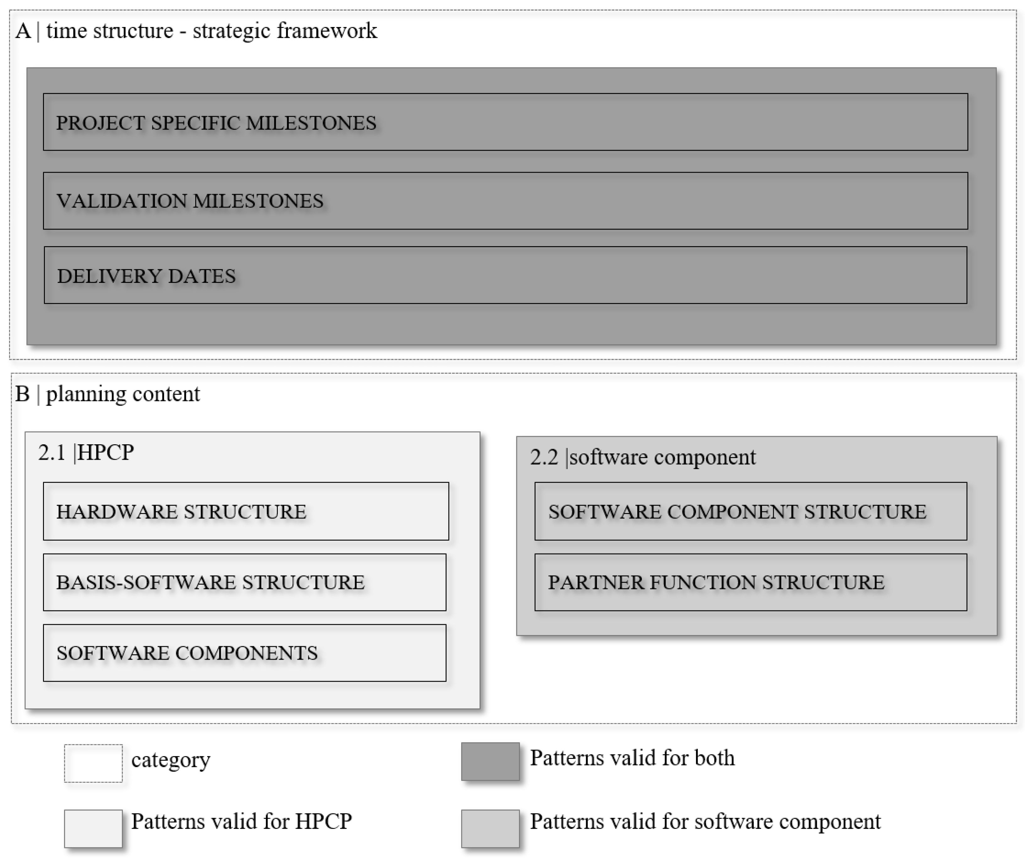
In this section, we present eight patterns that resulted from the procedure shown in the Section 4.3. Figure 1 shows the two categories (time structure–strategic framework and planning content) with the corresponding patterns. As already mentioned in Section 4.2, a distinction is made between two perspectives, which are considered in the patterns. Category A, time structure–strategic framework, is composed of the following three patterns: PROJECT SPECIFIC MILESTONES, VALIDATION MILESTONES and DELIVERY DATES. The procedure selected indicates that in category A no distinction is necessary for the respective perspective and therefore category A contains patterns that are valid for both views. A distinction has been made for category B, planning content, and thus category B includes patterns that have been developed explicitly for the respective view. Category B contains the following three patterns from the HPCP’s point of view: HARDWARE STRUCTURE, BASIS-SOFTWARE STRUCTURE and SOFTWARE COMPONENTS. From SWC’s view there are the two following patterns: SOFTWARE COMPONENT STRUCTURE and PARTNER FUNCTION STRUCTURE.

5.1. Time Structure–Strategic Framework

The first category, time structure–strategic framework, consists of three patterns that all refer to different types of milestones or deadlines and that all influence the release planning process in the automotive industry and thus represent a time schedule. There are types of milestones that characterize vehicle development and each type has its significance and influence on the development process. The various milestones that form the time structure are explained below in pattern form. The three presented patterns are valid for both views, as the strategic framework is binding for all development projects and therefore no distinction is necessary.

5.1.1. Project-Specific Milestones

Context: The project-specific milestones represent key milestones that emerge from each OEM’s product development process projected on the development project. These milestones contain required targets that have to be met to pass the gates. The project-specific development procedure has to be aligned to the required content of each milestone and has to be considered accordingly in the release planning. The automotive industry is a strictly regulated domain, which has to comply with numerous standards and legislations. For this reason, several milestones characterize the vehicle development and the associated release planning. These pre-defined milestones represent general dates that have to be considered and passed during the development process.
Problem: The strategic framework forms a time structure, which has to be considered during the initial creation of the release plan. From the project-specific milestones, a selection has to be made of which milestones are relevant for release planning, since the same milestones are not required for every development project.
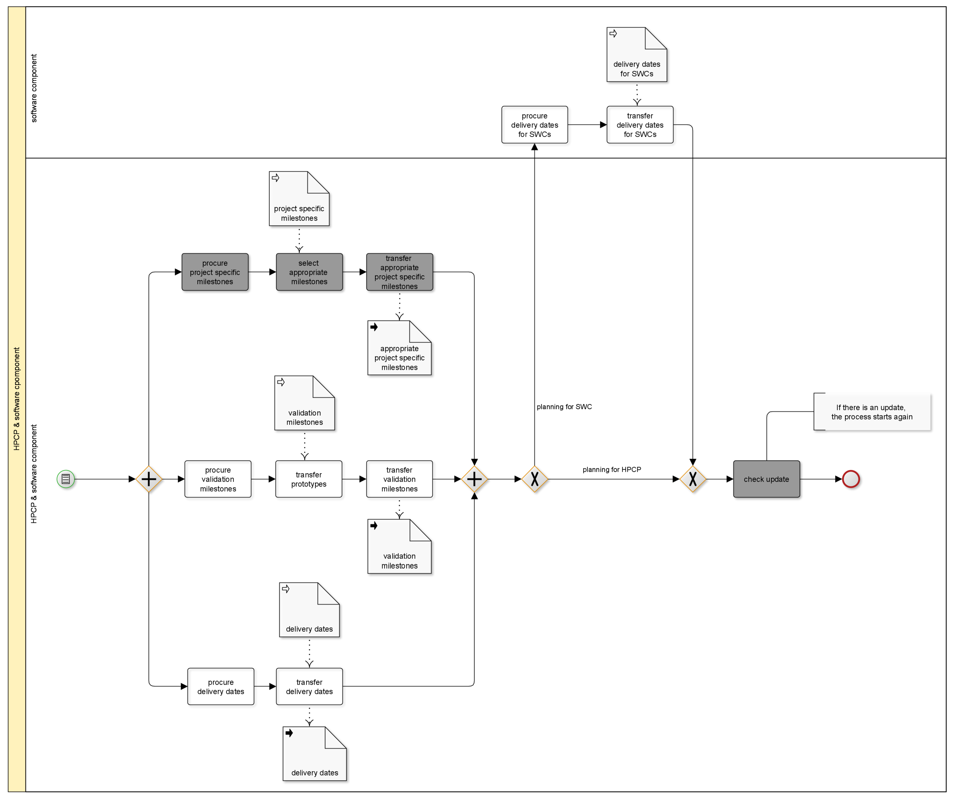
Solution: For the time structure required in release planning, the project-specific milestones have to be identified first and a selection has to be made. The selection of project-specific milestones will be transferred to the release plan in a further step.
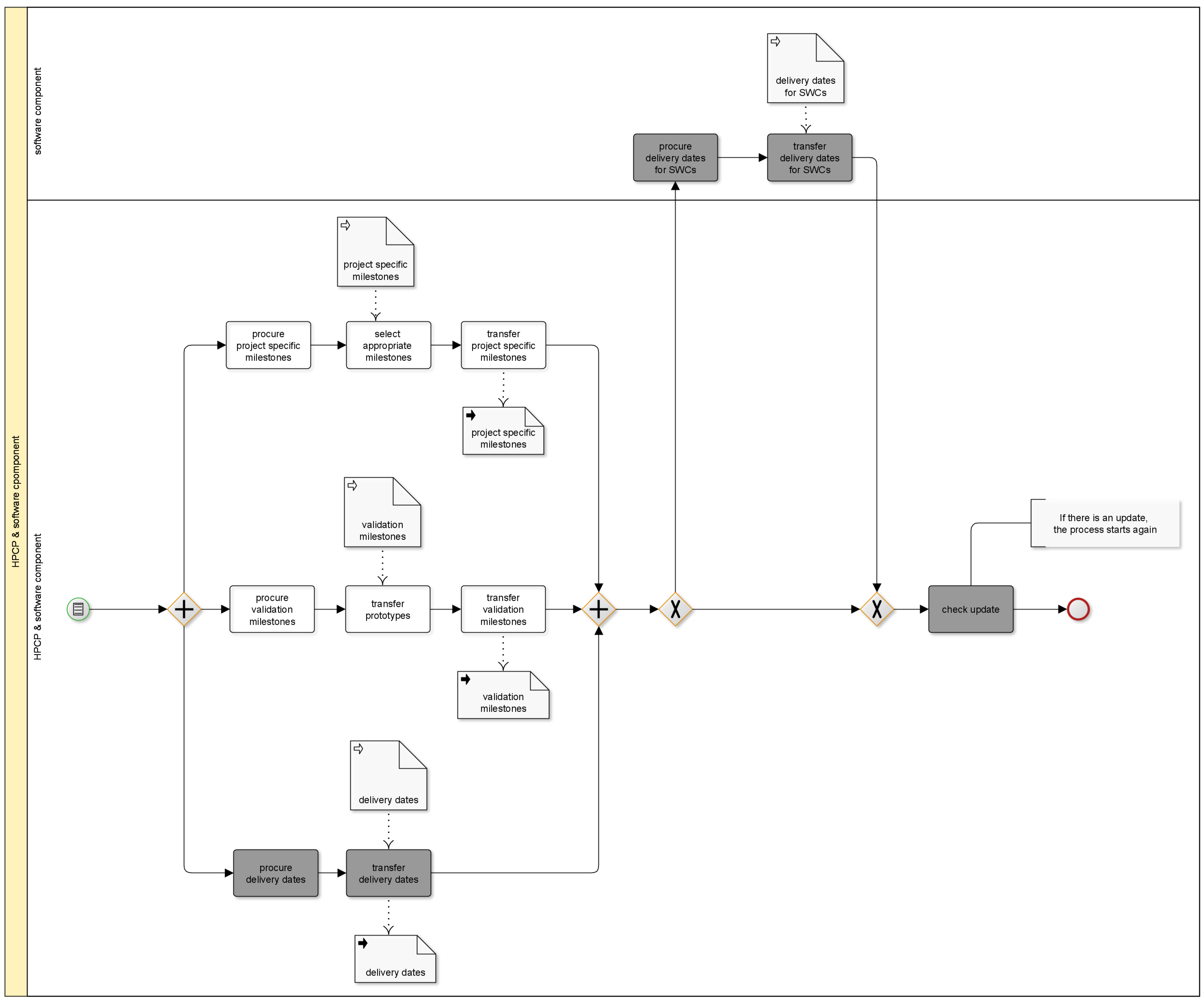
Solution sketch: The following Figure 2 shows all three patterns that are required for the transfer of the strategic framework. The activities relevant to this pattern PROJECT-SPECIFIC MILESTONES are marked in grey. Furthermore, Figure 2 shows the difference between the two perspectives (HPCP view and SWC view) and the respective activities. The holistic representation of all three patterns and the two perspectives makes both the relationships and the classification of the patterns in the overall context visible.
Result: The project-specific milestones form a generic basis for vehicle development and always relate to a concrete vehicle project. These milestones are planned specifically for the project and represent deadlines as a time structure in the release plan. These milestones have a major influence on release planning, as they are a rigid and time-based requirement that has to be adhered to. As a result, development activities are limited in time and the time frame for flexible planning is heavily affected. On the other hand, this predefined structure is necessary in vehicle development to ensure a certain level of commitment with regard to legal requirements and quality standards. Furthermore, due to the cross-linking and interdependence of the scopes, this framework is indispensable in order to achieve an appropriate alignment and coordination of the scopes. Each vehicle OEM has its own project-specific milestones. However, there are common basic features between the OEMs, which are designed differently depending on the philosophy and circumstances, and the result can therefore vary.
Related patterns: The PROJECT-SPECIFIC MILESTONES provide a basis and a mandatory time framework for all development projects. For this reason, there is a relationship to all subsequent patterns.
Example: Project-specific milestones represent general main milestones such as the start of production (SOP), which are defined for the vehicle to be developed. Figure 3 shows an example of various project-specific milestones with the corresponding vehicle development process divided into different phases.
These milestones are mandatory for all projects and represent the first pattern of the strategic framework.

5.1.2. Validation Milestones

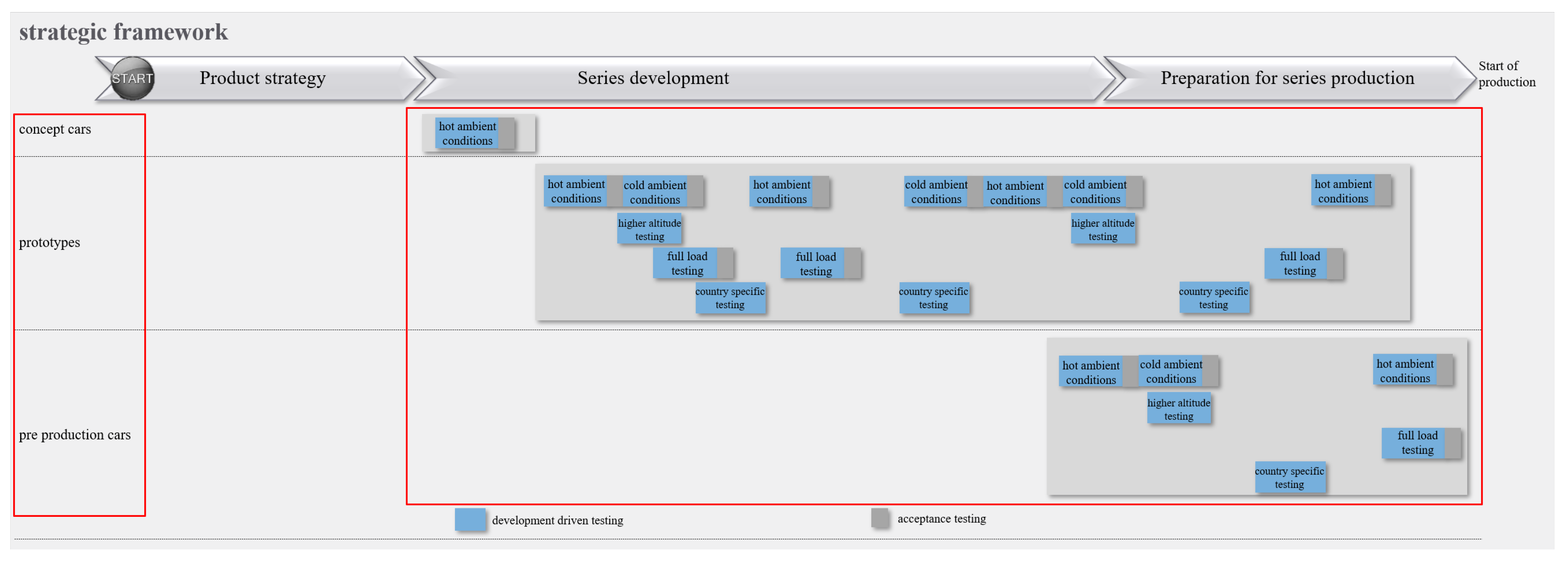
Context: The development of series production vehicles is achieved by successively building various test models. These prototype vehicles or testing vehicles follow a specific purpose and are characterized by respective testing. The testing associated with these structures takes place with a different group of participants. In addition, these prototypes are available in different versions and range from aggregate carriers to pre-series vehicles. The tests associated with these vehicles take place with a different group of participants. First, there are tests with management participation, which serve an acceptance purpose. Second, tests are of a purely developmental character and are performed with developers. Some types of testing take place under different climatic conditions (e.g. hot and cold ambient testing) and are conducted under different environmental conditions depending on the requirements of development scope (e.g. squeak and rattle testing and high-altitude testing). Furthermore, the test specific milestones include testing such as test drives in urban traffic, under maximal performance operation and country-specific testing.
Problem: The tests to be carried out are linked to climatic conditions and are therefore seasonally limited. This leads to an increasing complexity in the coordination and execution of the different tests with corresponding vehicles. The dependence on seasonal climatic conditions has to be incorporated at an early stage in the planning of the development scope. In addition, dependencies on other systems with different levels of maturity, which are not the focus of the respective testing, complicate consideration in the release plan. Due to climatic conditions and the time available, tests are carried out in parallel and are anticyclical. On the one hand, this saves time and, on the other hand, makes debugging more difficult when cold and hot ambient testing take place simultaneously. The preparation and post-processing of the vehicles, as well as transport routes to the test locations or even the import and export by customs, are activities that require a certain amount of time and should also be considered in the release plan.
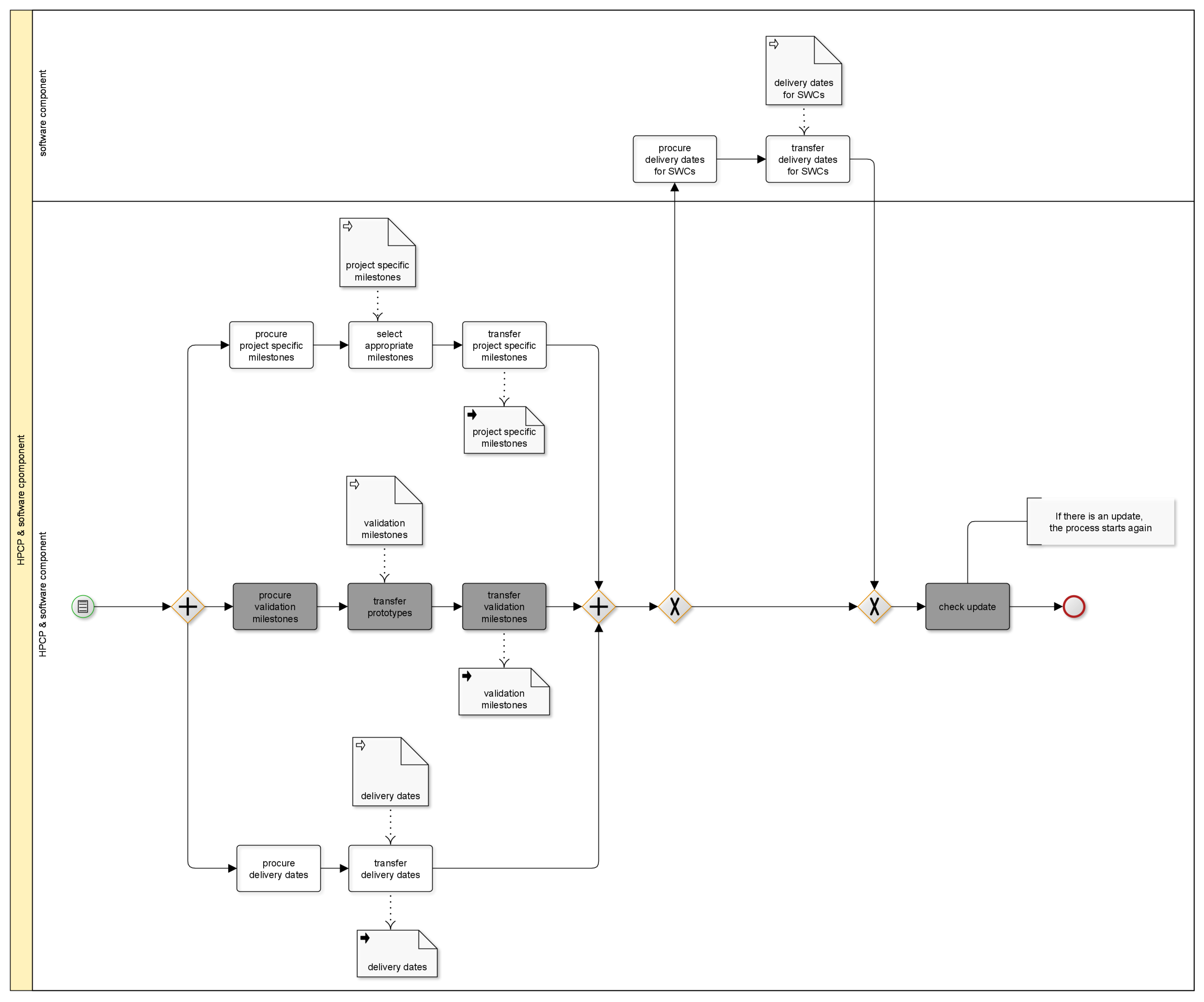
Solution: Both the structure of different testing vehicles and the associated test planning, including hot and cold ambient testing as well as all other testing types, are first identified and then incorporated into the release plan.
Solution sketch: The transfer of different prototypes and the validation milestones to the appropriate release plan is marked in grey in the solution sketch (see Figure 4).
Result: On the one hand, the validation milestones represent the different testing vehicles and serve to coordinate necessary testing with activities to be implemented. The structure of the testing vehicles is project-specific and has a corresponding effect on the test planning. These milestones are a further part of the strategic framework and control the upcoming development activities accordingly. As a result of this process step, both the prototypes and the validation milestones are now included in the release plan. The validation milestones are defined for a specific vehicle project, and since each OEM has its own milestones, the result can differ.
Related patterns: The validation milestones are based on the PROJECT SPECIFIC MILESTONES and are defined accordingly.
Example: Figure 5 sketches an example of the different testing vehicles with corresponding testing in the overall context.

5.1.3. Delivery Dates

Context: The ECU development process and its functional scope follow a release management system and it is divided into a certain number of releases, which are based on the product development process of each OEM. The integration and qualification of the ECU network with associated software is defined as an integration process that is the responsibility of release management. The number of releases and the corresponding artifact required are defined specifically for each OEM. At these specified dates, all parties involved deliver a new version of the product with the requested depth of testing. The depth of testing can vary depending on the product and may include different levels of testing. In the subsequent integration process, the delivered artifacts are subjected to further tests. Furthermore, planned release levels are observed in this release process.
Problem: The delivery dates are determined specific to the project and are already specified for the development projects by the OEM. These milestones represent a mandatory time framework that has to be considered in the development of the ECUs as well as of functions. They therefore represent dates that have to be reflected in the release plan and control the development process. The milestones therefore have a great influence on the flexible organization of the development process.
Solution: The delivery dates already set have to be procured first and transferred to the respective release plan for the corresponding development project. They represent dates when artifacts have to be provided in order to participate in the respective release.
Solution sketch: The transfer of the delivery dates with the corresponding activities to the appropriate release plan is marked in grey in the solution sketch (see Figure 6).
Result: The delivery dates ensure the bundling of required artifacts and its integration into the overall infrastructure of the development project. These deadlines are a constraint and the development of the respective product has to be aligned accordingly in order that the overall functionality can be integrated and tested on these deadlines. This achieves an early validation of the hardware as well as software scopes in the overall network, in order to take measures in time to ensure the required quality for SOP.
Related patterns: The delivery dates are based on both PROJECT-SPECIFIC MILESTONES and VALIDATION MILESTONES and are defined accordingly.
Example:Figure 7 shows examples of different delivery dates in the context of vehicle development.
Next, category B planning content is introduced.

5.2. Planning Content

The second category, planning content, contains an approach for structuring the content of the respective planning scope from both the hardware and software component point of view. In this section, we present one pattern, namely HARDWARE STRUCTURE, of this category (see Figure 1). There are separate patterns for each point of view, since each perspective focuses on a different planning level, resulting in a different planning content. The scope to be planned in a release plan strongly depends on the use case and that is why a distinction in this category is made. The first pilot project (HPCP) shows the content of an ECU release plan from a hardware perspective. The software component perspective is represented by the second project and contains planning contents on a detailed level. First, the patterns for the HPCP point of view are presented. The patterns of the software functions’ perspective follow afterwards.
First, the patterns for HPCPs are presentend.

5.2.1. Hardware Structure

Context: With the use of control units, the processing of sensor signals can be carried out via control algorithms by an adapted actuation of actuators. Essentially, control units in a vehicle consist of the components hardware, software and a sensor-actuator component. The hardware consists of a microcontroller or processor with required peripherals, a power supply, and a sensor-actuator control. At the beginning of series development, the hardware is at a high level of development and is therefore presented in the form of a representative sample.
Problem: At the beginning of series development, a high level of hardware development is required since the hardware serves as the basic framework for the basic software and software components that are built on it. Nevertheless, a partial scope of development activities remains, which has to be included in the release plan.
Solution: The hardware must first be identified and can be divided into further elements that are then transferred to the release plan. The development of the hardware is well advanced at the beginning of the series development and, for this reason, only the remaining development scope is listed in the release plan.
Solution sketch: The transfer of the hardware as part of the content structure of a release plan is shown in the solution sketch (see Figure 8).
Result: Hardware as part of the content structure of the control unit is often built on platforms provided by a supplier. Due to the high level of development at the beginning of series development, no high planning effort is required for the hardware. The scopes that are nevertheless further developed or updated have an impact on the basic software as well as on the software components. In order to attain an overview of these effects and to be able to communicate them, the remaining development scopes are listed in the plan.
Example: The following Figure 9 provides an example of the hardware as part of an ECU in the release plan.
Related patterns: The hardware as a part of the content structure of an ECU is developed according to established project-specific milestones. For this reason, there is a relationship to PROJECT SPECIFIC MILESTONES.

5.2.2. Basis Software Structure

Context: The basic software of an ECU, similar to the associated hardware, has to have a certain software status at the beginning of series development, so that a basic functionality such as hardware-related functions like drivers and memory management are guaranteed. Furthermore, basic software includes scopes that are further developed in the process of development or represent new developments. This includes, for example, functions such as the communication connection (internal/external) and bus systems used. Further components of the basic software, listed in the release plan, are operating system functions such as diagnostic capability, safety features and update options. These basic functionalities grow with the simultaneous development of the software components and are stated in the release plan. The hardware-related scopes that have already been developed at the beginning are not included in the release plan.
Problem: The basic software has to provide a certain basic functionality similar to the hardware at the beginning of the series development, so that a basis for the software components based on it exists. Changes that affect the basic software are linked to defined milestones that are communicated to those involved.
Solution: The scope of the basic software, representing development activities in the further process of series development, has to be identified first and can be specified in more detail. The remaining development activities are then transferred to the release plan.
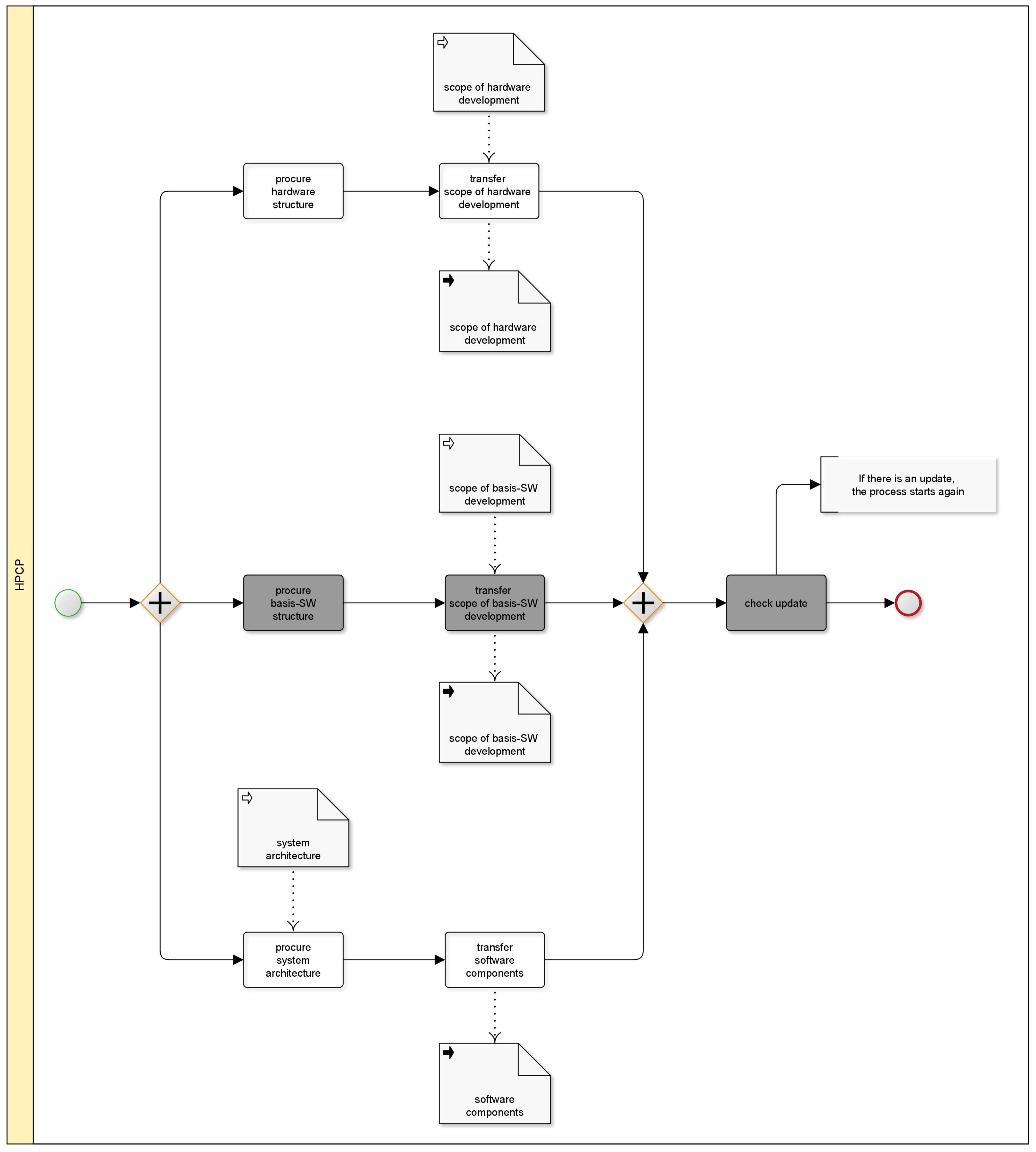
Solution sketch: The transfer of the basic software as an object of the content structure of a release plan is shown in grey in the solution sketch (see Figure 10).
Result: The basic software that is used to configure a network of ECUs is another element of the planning scope of an ECU and is included in the release plan with certain scopes. The basic software forms the foundation for the software components based on it and provides the connection between hardware and software components. It is the responsibility of each OEM to decide which scope of the basic software is explicitly included in the release plan and thus planned.
Example: The following Figure 11 shows an example of how the basic software can be listed with possible scopes in the release plan of an ECU.
Related patterns: The basic software as part of the content structure of an HPCP is the foundation for the pattern SOFTWARE COMPONENTS and is the prerequisite for the working software components. The basic software is in its functionality directly connected to the hardware and therefore has a direct relationship to the pattern HARDWARE STRUCTURE.

5.2.3. Software Components

Context: Software components are located on a control unit that perform certain functions through signal processing. They are organized in independent organizational units of the application software of an ECU. These components impose specific and different requirements on the ECU in order to be executable.
Problem: Individual software components of an ECU are listed and defined in the software architecture. These software components are developed during series development and require certain access mechanisms as well as connection specifications to the basic software. Implementing the requirements of the software components influences the subsequent release planning of an HPCP. The requirements of software components affect the content of releases and influence the integration process and the associated coordination activities.
Solution: These components as part of the content structure of an HPCP are first identified and then transferred to the release plan.
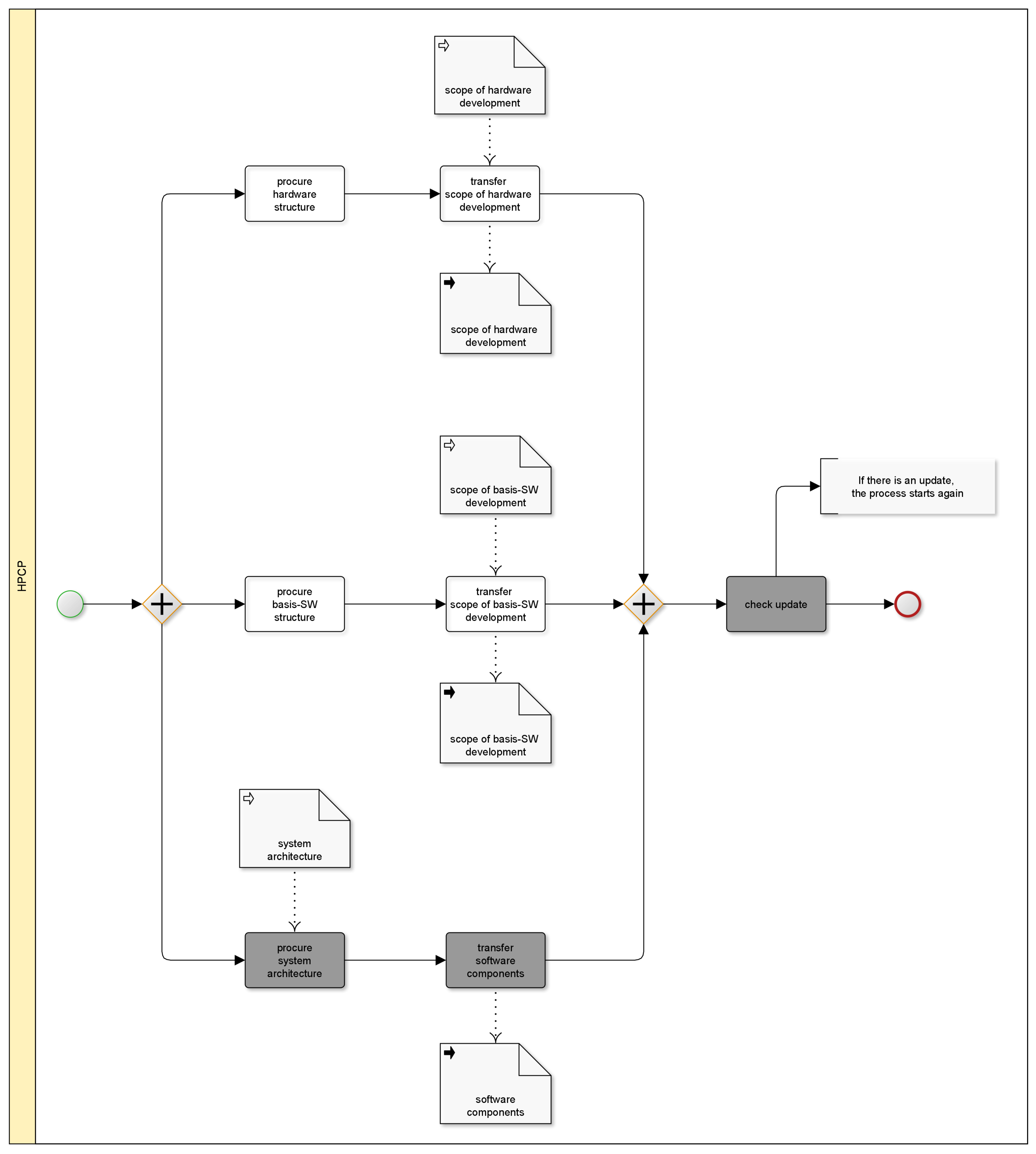
Solution sketch: The transfer of software components as part of the content structure of a release plan is shown in grey in the solution sketch (see Figure 12).
Result: Software components encapsulate implementation details and are an important structuring element of the entire control unit software. Software components located on an ECU are listed in the release plan of the HPCP and implement the functions of an application. Software components, as a decoupled, functional-bearing application layer, have standardized interfaces and can, in principle, be relocated at any place within the ECU network.
Example: The following Figure 13 shows an example of the listing of different software components as part of the content structure of an HPCP.
Related patterns: The software components are related to the BASIC SOFTWARE STRUCTURE pattern because they are directly based on the basic software.
Now the patterns for Software Components are presentend.

5.2.4. Software Component Structure

Context: Software components located on a control unit can be divided into further individual executable elements and detailed. Such subdivision is taken from the software architecture and is a template for subdividing the entire software components into sub functions. In planning, each sub-function should be a logical and closed unit so that they can be planned independently of one another and yet still consider the dependencies between them.
Problem: The subdivision of software components into individual sub functions has to be made for a suitable detail level. The planning effort increases immeasurably as the detail level of the sub functions increases, and there is no added value from a planning perspective. If too little detail is chosen for the sub functions, the dependencies of the sub functions on each other can no longer be displayed. For this reason, a suitable detail level of the sub functions is necessary for successful release planning.
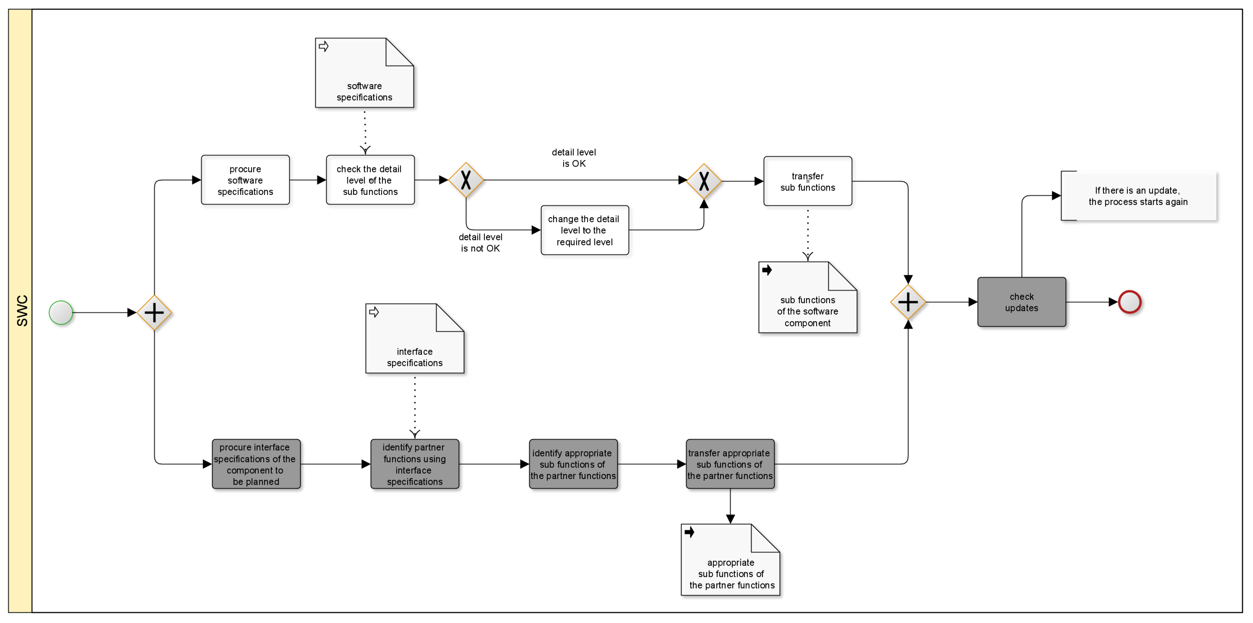
Solution: The sub functions, representing in total the entire software component, are first checked for the required level of detail and if necessary, the level of detail of the sub functions is adjusted. Then all sub functions are transferred to the release plan.
Solution sketch: The transfer of sub functions as part of the structure of the release plan of a software component is highlighted in grey in the solution sketch (see Figure 14).
Result: The individual elements of a software component in the form of sub functions represent the software component as a whole. The entire software component exists in the form of sub functions in the plan in the appropriate level of detail. The list of sub functions forms the basis for the subsequent detailed planning of the content. The representation of the sub function as an individually listed planning unit is a basic prerequisite for representing the dependencies of the sub function.
Example: The following Figure 15 illustrates an example of listing various sub functions as part of the content structure of a software component.
Related patterns: The sub functions are part of the content structure of the software component. There is a relationship between the SOFTWARE COMPONENT STRUCTURE and BASIC SOFTWARE STRUCTURE patterns since the software components place requirements on the basic software.

5.2.5. Partner Function Structure

Context: In most cases, there are dependencies of software components on one ECU or dependencies to software components located on another ECU. Partner functions are sub functions of other software components that are linked to sub functions of the software component in the network and exchange or provide information during operation using this interface. They are mutually dependent on each other, meaning the development of the technical interfaces has to be incorporated in the release plan. Input and output interfaces of the sub functions are specified in the interface specification, indicating the sub functions of the partner functions.
Problem: The partner functions of a software component have to be identified in order to derive the sender-receiver communication. In agreement with both sides, a suitable detailed level of partner functions and sub functions needs to be defined. This should be a mutual exchange since the networked software components only have knowledge of its own structure but not of the other structure in detail.
Solution: The different partner functions are first identified and then transferred to the release plan.
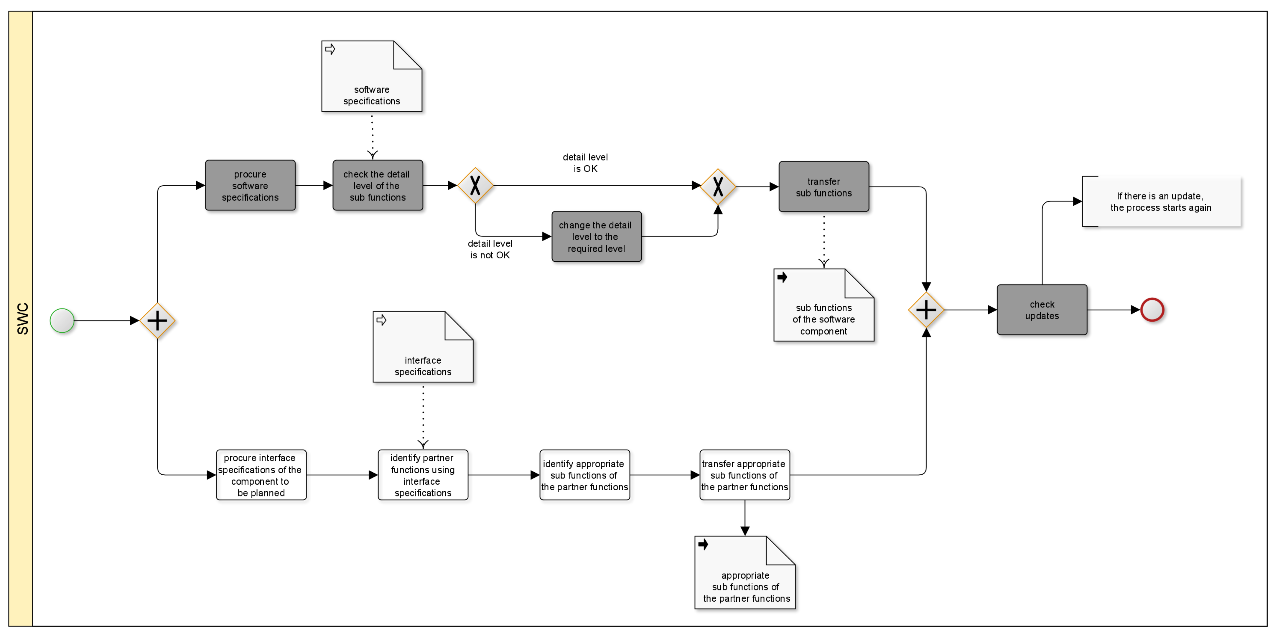
Solution sketch: The transfer of partner functions as an element of the content structure of the release plan of a software component is marked grey in the solution sketch (see Figure 16).
Result: The partner functions are part of the content structure of the release plan of the software component and are listed in the release plan. The existing dependencies between a software component and a partner function affect the development activities of both parties. For this reason, partner functions are part of the content structure of a software component and are included in the release plan. As a result, existing input and output values of the software component are considered in the release plan.
Example: The following Figure 17 contains a possible listing of different partner functions of different software components.
Related patterns: Due to the dependency and existing interfaces there is a relationship to the pattern SOFTWARE COMPONENT STRUCTURE.
5.3. Visualisation of the Patterns in an Initial Release Plan

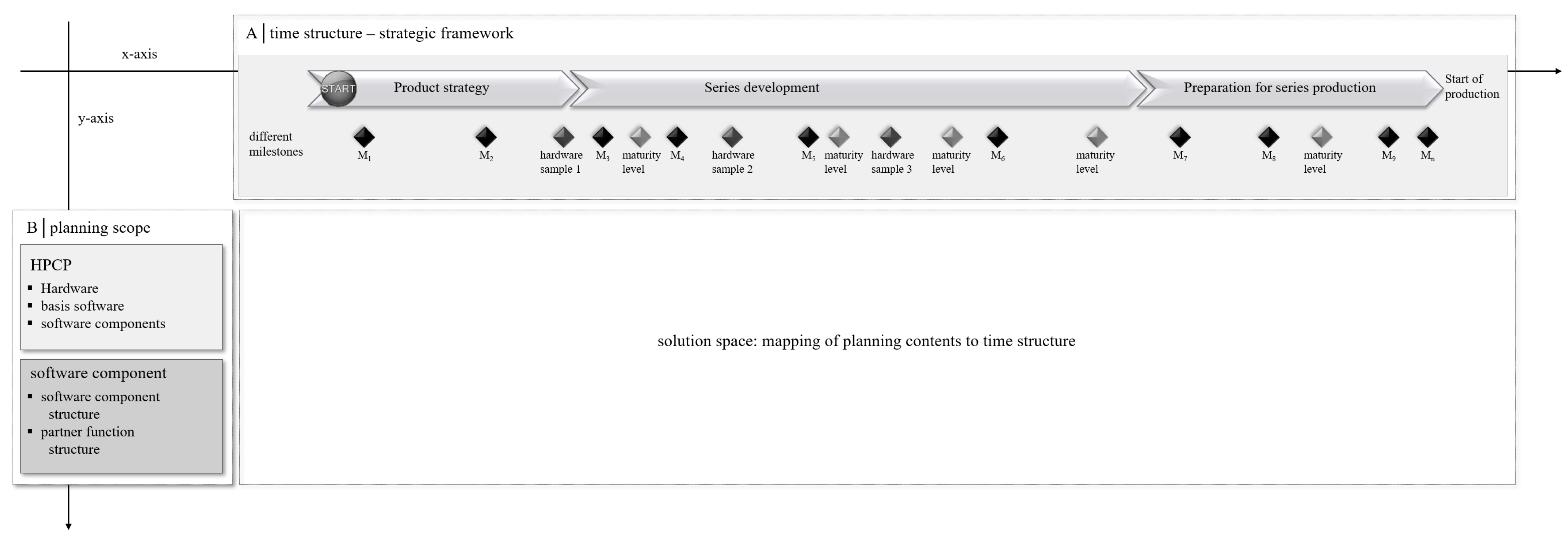
In order to visualise a structural relationship between the patterns in an initial release plan, we created Figure 18. Figure 18 illustrates two categories with its corresponding patterns and how they are reflected in an initial release plan. Category A, time structure–strategic framework, constitutes the x-axis of a release plan and category B, planning content, defines the y-axis.
These axes, meaning the two categories, form the solution space. In the context of Figure 18, the solution space represents the part of a release plan in which the detailed planning contents are assigned to the releases.
Figure 18 shows one possible form of a representation the user can obtain. However, the patterns themselves do not specify a visualisation. The structure in Figure 18 is based on the results of the two pilot projects, which independently demonstrate a similar structure of the release plan.

6. Discussion

Release planning is an essential task for delivering a product in the required quality at a specific time. We have presented release planning patterns in Section 5 to determine the strategic framework and to identify the planning content. Previously there has been no general approach for a structured process to set up an initial release plan for software and hardware engineering. To fill this gap, we created release planning patterns for initial release planning in the automotive industry. The patterns provide a solution regarding the influencing factors to be considered (category A) and they show how to structure the planning content from a software and hardware perspective (category B). With the patterns from category A, the user receives a detailed solution about specific factors that define the timeline. The patterns contained in category B show for both an HPCP and an SWC how these can be planned in detail.
The patterns were developed through two pilot projects by Dr. Ing. h. c. F. Porsche AG as well as reviewed by another OEM (Audi AG) and further experts. This ensures that the patterns can be applied to other OEMs. However, a deeper validation is necessary for an extension of the patterns by companies with conditions (regulated domains, complex supplier relationships and high safety requirements) similar to those in the automotive industry. In addition, the patterns should be applied to other projects to confirm their applicability through testing with physical objects. In future, we plan to evaluate the presented patterns with further companies.
A great advantage of the presented patterns are the elements example and solution sketch. The user benefits not only from the generally valid description of creating an initial release plan, but above all from application-related examples gained from practical experience. The solution sketches are instructions on what exactly has to be done. With the input data, the user knows what is needed for this and what can be expected as a result during and after the sub-processes.
Another section included in the patterns is the element related pattern. This element shows the connections that can occur between different patterns. There are no direct relationships between the predetermined influencing factors and the way in which both software and hardware are listed in detail in the release plan. The structure of how an HPCP and an SWC are handled in the release plan can be created independently of the time structure. Nevertheless, the patterns from category A are mandatory influencing factors from both a software and hardware perspective and require consideration in the release plan.
The patterns presented in this paper represent a general description of an initial release plan. This applies independently of the following two aspects: development project and development method. It is irrelevant whether the development project is a hardware or software development, as the patterns were developed for both perspectives and can be applied from both views. During the pattern creation, consideration was given when a distinction was necessary and thus different patterns are to be developed for the respective perspectives.
The patterns are suitable for both agile and traditional development based on the two pilot projects. No distinction is made for the application of the patterns. We discussed whether the patterns are also applicable for the following constellations. The ECU is developed traditionally or in an agile way and the same applies to the software component. We concluded that whether an ECU is developed traditionally or with agile methods has no effect. The individual components of an ECU that have to be planned are to be selected independently of the development method. The same is true for the software component. Whether a software component is developed traditionally has no effect. In this case, too, the detailed planning structure remains the same regardless of the chosen development method.
Vehicles do not only consist of software, since the hardware as a material component is also of essential importance, as the software is located on it. It only makes limited sense to consider the software alone. For this reason, both a hardware project and a software project were selected during the development of the patterns to make the patterns applicable to both views. Numerous software functions of different control units are centralised in the new technology of the HPCP. An HPCP was deliberately selected as the project for creating the patterns, as it represents the state-of-the-art and a complex example. The complex interaction between hardware and associated SWCs is reflected in the planning of the basic software. Here, the requirements of both the hardware and the SWCs have to be taken into account. It is therefore essential to consider these scopes holistically. Today’s vehicles not only consist of HPCPs, but also contain less complex ECUs. Accordingly, the patterns are appropriate for any type of control unit. The basic structure of ECUs is the same for all of them. They only differ in the SWCs that are located on them. For this reason, the patterns are versatile and can also be applied to other domains such as the rail industry or aircraft construction, but this still needs to be validated.
With the patterns described in this work, two categories that are part of the initial release plan have been presented. The patterns presented in this work close the research gap where, until now, there have been no patterns for the creation of a timeline as well as no patterns for suitable planning objects. The numerous milestones and requirements imposed by legislation in the automotive industry restrict the scope and flexibility of vehicle development. This makes general approaches in the form of these patterns, which address this complexity and offer the user guidance in creating a suitable time structure in the release plan, all the more necessary. The patterns on the planning objects and the examples contained therein provide meaningful planning levels for both hardware and software, so that planning is not too detailed but also not too approximate and release planning is feasible. With the patterns we presented, the framework (the x- and y-axis of a release plan) is defined. Another category with associated patterns could represent the actual mapping of the development content to the releases. We recommend using our patterns to capture the time structure of a release plan. Furthermore, the patterns serve as a structured procedure for considering the relevant planning content.

7. Conclusions and Future Work

Today’s vehicles, but also those of the future, will be characterized by software. This means that the planning and development of the software and hardware installed in the vehicle will become increasingly important. New legal requirements extend the existing requirements for hardware and software development. As a result, the complexity of factors influencing release planning is also enhanced. Release planning, consisting in its core task of assigning content to releases, is a complicated matter itself. Due to the lack of a general approach, such as hard constraints influencing release planning in the automotive industry and the way release plans are created, we presented eight release planning patterns. The patterns belonging to the category time structure–strategic framework address the firmly defined milestones, providing a binding timeline. Project-specific milestones, testing vehicles and test phases, as well as the delivery dates, which are valid for both hardware and software development, are included. The planning content from the HPCP and software component view is covered by the patterns from category B. From the HPCP perspective, three components—hardware, basic software and the software components—are planned. In its release plan, the software component itself lists sub functions and sub functions of partner functions that represent the scope of planning.
The results demonstrated offer support to release planners and other interested users for their own solution. Using a structured, practice-based approach, we demonstrated how to deal with the given framework conditions and what should be considered as planning content from an HPCP and software component point of view. The relationships between the individual patterns reveal interactions and the complexity of release plans. The patterns point out that further patterns should be created and added in order to create a comprehensive initial release plan. We are already working on further patterns. In the future, we want to create a pattern language for release planning that considers and connects all the patterns. The coherent description is intended to provide a better understanding, structure and creation of release plans from both a hardware and software perspective.

Author Contributions

Conceptualization, K.M., S.W. and G.R.; methodology, K.M. and S.W.; validation, K.M., S.W. and G.R.; investigation, K.M.; data curation, K.M.; writing—original draft preparation, K.M.; writing—review and editing, K.M., S.W. and G.R.; visualization, K.M.; supervision, K.M., S.W. and G.R. All authors have read and agreed to the published version of the manuscript.

Funding

This research received no external funding.

Institutional Review Board Statement

Not applicable.

Informed Consent Statement

Informed consent was obtained from all subjects involved in the study. Written informed consent has been obtained from the patient(s) to publish this paper.

Data Availability Statement

Not applicable.

Conflicts of Interest

The authors declare no conflict of interest.

Abbreviations

The following abbreviations are used in this manuscript:
ECUElectric Control Unit
E/EElectrical/Electronic
HPCPHigh-Performance Computing Platform
HWHardware
OEMOriginal Equipment Manufacturer
SOPStart Of Production
SWCSoftware Component
SWSoftware

References

  1. Unseld, R. The development trends toward vehicle computer architecture. ATZelectronics Worldw. 2020, 15, 14–17. [Google Scholar] [CrossRef]
  2. Burkacky, O.; Deichmann, J.; Stein, J.P. Automotive Software and Electronics 2030. 2021. Available online: https://www.mckinsey.com/industries/automotive-and-assembly/our-insights/disruptive-trends-that-will-transform-the-auto-industry/de-de (accessed on 26 April 2021).
  3. Antinyan, V. Revealing the complexity of automotive software. In Proceedings of the 28th ACM Joint Meeting on European Software Engineering Conference and Symposium on the Foundations of Software Engineering, Sacramento, CA, USA, 16 November 2020; Devanbu, P., Cohen, M., Zimmermann, T., Eds.; ACM: New York, NY, USA, 2020; pp. 1525–1528. [Google Scholar] [CrossRef]
  4. Friedrich, H.E.; Ulrich, C.; Schmid, S. New vehicle concepts for future business model. In 19. Internationales Stuttgarter Symposium; Bargende, M., Reuss, H.C., Wagner, A., Wiedemann, J., Eds.; Springer Fachmedien Wiesbaden: Wiesbaden, Germany, 2019; Volume 76, pp. 815–829. [Google Scholar] [CrossRef]
  5. Lindgren, M.; Land, R.; Norstr, C.; Wall, A. Key Aspects of Software Release Planning in Industry. In Proceedings of the 19th Australian Conference on Software Engineering (aswec 2008), Perth, WA, Australia, 26–28 March 2008; pp. 320–329. [Google Scholar] [CrossRef]
  6. Ruhe, G. Product Release Planning: Methods, Tools, and Applications; CRC Press: Boca Raton, FL, USA, 2010. [Google Scholar]
  7. Bock, F.; Sippl, C.; Siegl, S.; German, R. Status Report on Automotive Software Development. In Automotive Systems and Software Engineering; Dajsuren, Y., van den Brand, M., Eds.; Springer International Publishing: Cham, Switzerland, 2019; Volume 39, pp. 29–57. [Google Scholar] [CrossRef]
  8. Abel, H.B.; Blume, H.J.; Brabetz, L.; Broy, M.; Fürst, S.; Ganzelmeier, L.; Helbig, J.; Heyen, G.; Jipp, M.; Kasties, G.; et al. Elektrik/Elektronik/Software. In Vieweg Handbuch Kraftfahrzeugtechnik; Pischinger, S., Seiffert, U., Eds.; Springer Fachmedien Wiesbaden: Wiesbaden, Germany, 2016; pp. 925–1104. [Google Scholar] [CrossRef]
  9. Saliu, O.; Ruhe, G. Supporting Software Release Planning Decisions for Evolving Systems. In Proceedings of the 29th Annual IEEE/NASA Software Engineering Workshop, Greenbelt, MD, USA, 6–7 April 2005; pp. 14–26. [Google Scholar] [CrossRef]
  10. Directive2007/46/EG. For European Vehicles. Available online: https://eur-lex.europa.eu/legal-content/DE/TXT/?uri=celex%3A32007L0046 (accessed on 20 May 2020).
  11. Ameller, D.; Farré, C.; Franch, X.; Rufian, G. A Survey on Software Release Planning Models. In Product-Focused Software Process Improvement; Lecture Notes in Computer Science; Abrahamsson, P., Jedlitschka, A., Nguyen Duc, A., Felderer, M., Amasaki, S., Mikkonen, T., Eds.; Springer International Publishing: Cham, Switzerland, 2016; Volume 10027, pp. 48–65. [Google Scholar] [CrossRef] [Green Version]
  12. Svahnberg, M.; Gorschek, T.; Feldt, R.; Torkar, R.; Saleem, S.B.; Shafique, M.U. A systematic review on strategic release planning models. Inf. Softw. Technol. 2010, 52, 237–248. [Google Scholar] [CrossRef]
  13. Szőke, Á. Conceptual scheduling model and optimized release scheduling for agile environments. Inf. Softw. Technol. 2011, 53, 574–591. [Google Scholar] [CrossRef]
  14. Li, C.; van den Akker, M.; Brinkkemper, S.; Diepen, G. An integrated approach for requirement selection and scheduling in software release planning. Requir. Eng. 2010, 15, 375–396. [Google Scholar] [CrossRef] [Green Version]
  15. Greer, D.; Ruhe, G. Software release planning: An evolutionary and iterative approach. Inf. Softw. Technol. 2004, 46, 243–253. [Google Scholar] [CrossRef] [Green Version]
  16. Ruhe, G.; Ngo The, A. Hybrid Intelligence in Software Release Planning. Int. J. Hybrid Intell. Syst. 2004, 1, 99–110. [Google Scholar] [CrossRef]
  17. Felderer, M.; Beer, A.; Ho, J.; Ruhe, G. Industrial evaluation of the impact of quality-driven release planning. In Proceedings of the 8th ACM/IEEE International Symposium on Empirical Software Engineering and Measurement—ESEM ’14, Torino, Italy, 18–19 September 2014; Morisio, M., Ed.; ACM Press: New York, NY, USA, 2014; pp. 1–8. [Google Scholar] [CrossRef]
  18. Colares, F.; Souza, J.; Carmo, R.; Pádua, C.; Mateus, G.R. A New Approach to the Software Release Planning. In Proceedings of the 2009 XXIII Brazilian Symposium on Software Engineering, Fortaleza, Brazil, 5–9 October 2009; pp. 207–215. [Google Scholar] [CrossRef]
  19. Wohlin, C.; Aurum, A. What is important when deciding to include a software requirement in a project or release? In Proceedings of the 2005 International Symposium on Empirical Software Engineering, Noosa Heads, Australia, 17–18 November 2005; pp. 237–246. [Google Scholar] [CrossRef]
  20. Danesh, A.S. A Pattern-Based Release Planning Methodology for Market-Driven Software. Ph.D. Thesis, University of Malaya, Kuala Lumpur, Malaysia, 2016. [Google Scholar]
  21. Marner, K.; Theobald, S.; Wagner, S. Release Planning in a Hybrid Project Environment. In Advances in Agile and User-Centred Software Engineering; Lecture Notes in Business Information, Processing; Przybyłek, A., Morales-Trujillo, M.E., Eds.; Springer International Publishing: Cham, Switzerland, 2020; Volume 376, pp. 19–40. [Google Scholar] [CrossRef]
  22. Sax, E.; Reussner, R.; Guissouma, H.; Klare, H. A Survey on the State and Future of Automotive Software Release and Configuration Management; KIT: Amsterdam, The Netherlands, 2017. [Google Scholar]
  23. Bestfleisch, U.; Herbst, J.; Reichert, M. Requirements for the Workflow-based Support of Release Management Processes in the Automotive Sector. In Proceedings of the 12th European Concurrent Engineering Conference (ECEC’05), Toulouse, France, 11–13 April 2005; pp. 130–134. [Google Scholar]
  24. Müller, D.; Herbst, J.; Hammori, M.; Reichert, M. IT Support for Release Management Processes in the Automotive Industry. In Business Process Management; Lecture Notes in Computer Science; Hutchison, D., Kanade, T., Kittler, J., Kleinberg, J.M., Mattern, F., Mitchell, J.C., Naor, M., Nierstrasz, O., Pandu Rangan, C., Steffen, B., et al., Eds.; Springer: Berlin/Heidelberg, Germany, 2006; Volume 4102, pp. 368–377. [Google Scholar] [CrossRef]
  25. Alexander, C. A Pattern Language: Towns, Buildings, Construction; Oxford University Press: Oxford, UK, 1977. [Google Scholar]
  26. Gamma, E. Design Patterns: Elements of Reusable Object-Oriented Software; Pearson Education India: Delhi, India, 1995. [Google Scholar]
  27. Buschmann, F.; Henney, K.; Schmidt, D. Pattern-Oriented Software Architecture: A Pattern Language for Distributed Computing. Volume 4, 1st ed.; Wiley Series in Software Design Patterns; John Wiley & Sons: New York, NY, USA, 2007. [Google Scholar]
  28. Marner, K.; Wagner, S.; Ruhe, G. Stakeholder identification for a structured release planning approach in the automotive domain. Requir. Eng. 2020, 27, 211–230. [Google Scholar] [CrossRef]
  29. Fehling, C.; Barzen, J.; Breitenbücher, U.; Leymann, F. A process for pattern identification, authoring, and application. In Proceedings of the 19th European Conference on Pattern Languages of Programs—EuroPLoP ’14, Irsee, Germany, 9–13 July 2014; Eloranta, V.P., van Heesch, U., Eds.; ACM Press: New York, NY, USA, 2014; pp. 1–9. [Google Scholar] [CrossRef]
  30. Meszaros, G.; Doble, J. A pattern language for pattern writing. Pattern Lang. Program Des. 1998, 3, 529–574. [Google Scholar]
  31. Harrison, N.B.; Avaya Inc. Advanced Pattern Writing Patterns for Experienced Pattern Authors; Citeseer: University Park, PA, USA, 2006. [Google Scholar]
  32. Harrison, N.B. The language of shepherding. Pattern Lang. Program Des. 1999, 5, 507–530. [Google Scholar]
  33. Wellhausen, T.; Fiesser, A. How to write a pattern? In Proceedings of the 16th European Conference on Pattern Languages of Programs—EuroPLoP ’11, Irsee, Germany, 13–17 July 2011; Avgeriou, P., Fiesser, A., Eds.; ACM Press: New York, New York, USA, 2011; pp. 1–9. [Google Scholar] [CrossRef]
  34. Fehling, C. Cloud Computing Patterns: Fundamentals to Design, Build, and Manage Cloud Applications; Computer Science; Springer: Vienna, Austria, 2014. [Google Scholar]
  35. Wohlin, C.; Runeson, P.; Höst, M. Experimentation in Software Engineering; Springer Science & Business Media: New York, NY, USA, 2012. [Google Scholar]
Figure 1. Overview of the release planning patterns.
Computers 11 00089 g001
Figure 2. Activity diagram for pattern PROJECT SPECIFIC MILESTONES.
Computers 11 00089 g002
Figure 3. Example of three different project-specific milestones and how they can be placed in the timeline.
Computers 11 00089 g003
Figure 4. Activity diagram for pattern VALIDATION MILESTONES.
Computers 11 00089 g004
Figure 5. Example of three different validation milestones and how they can be placed in the timeline.
Computers 11 00089 g005
Figure 6. Activity diagram for pattern DELIVERY DATES.
Computers 11 00089 g006
Figure 7. Example of delivery dates and how they can be placed in the timeline.
Computers 11 00089 g007
Figure 8. Activity diagram for pattern HARDWARE STRUCTURE.
Computers 11 00089 g008
Figure 9. Example of a breakdown of the hardware structure into planning objects.
Computers 11 00089 g009
Figure 10. Activity diagram for pattern BASIS SOFTWARE STRUCTURE.
Computers 11 00089 g010
Figure 11. Example of a breakdown of the basis software structure into planning objects.
Computers 11 00089 g011
Figure 12. Activity diagram for pattern SOFTWARE COMPONENTS.
Computers 11 00089 g012
Figure 13. Example of a breakdown of the software component into planning objects.
Computers 11 00089 g013
Figure 14. Activity diagram for pattern SOFTWARE COMPONENT STRUCTURE.
Computers 11 00089 g014
Figure 15. Example of a breakdown of the software component structure into planning objects.
Computers 11 00089 g015
Figure 16. Activity diagram for pattern PARTNER FUNCTION STRUCTURE.
Computers 11 00089 g016
Figure 17. Example of a breakdown of the partner function structure into planning objects.
Computers 11 00089 g017
Figure 18. Visualisation of the presented patterns in an initial release plan.
Computers 11 00089 g018
Publisher’s Note: MDPI stays neutral with regard to jurisdictional claims in published maps and institutional affiliations.