Abstract
Crowd systems play an important role in virtual environment applications, such as those used in entertainment, education, training, and different simulation systems. Performance and scalability are key factors, and it is desirable for crowds to be simulated with as few resources as possible while providing variety and realism for agents. This paper focuses on improving the performance, variety, and usability of crowd animation systems. Performing the blending operation on the Graphics Processing Unit (GPU) side requires no additional memory other than the source and target animation streams and greatly increases the number of agents that can simultaneously transition from one state to another. A time dilation offset feature helps applications with a large number of animation assets and/or agents to achieve sufficient visual quality, variety, and good performance at the same time by moving animation streams between the running and paused states at runtime. Splitting agents into parts not only reduces asset creation costs by eliminating the need to create permutations of skeletons and assets but also allows users to attach parts dynamically to agents.
1. Introduction
Crowd simulations are one of the most important components in computer graphics applications today. Several video games (such as FIFA®, Ubisoft’s Assassin’s Creed®, and RockStar’s Grand Theft Auto® series), phobia treatment applications, and evacuation planning software (such as Thunderhead’s Pathfinder software®) use crowd simulation to create realistic environments. Simulating and rendering crowds is an expensive operation, and various techniques have been developed in the past to optimize the resources needed and have as many agents as possible.
Previous applications that animate and render large crowds suffer from having only a small number of different animated characters, which results in the variety of animations split between individuals in the crowd not being perceived by human users. We also found that existing applications and solutions have limited ability to define high-quality assets and reuse characters. The goal of our work is to address these limitations at a lower technical level and leverage more GPU computing power rather than using CPU to animate large crowds, as previous solutions have done. Asset creation issues are also addressed in our work through a novel method for splitting characters into parts.
In our paper, by agent, we mean an individual visible entity in the crowd. The entities can be humans, cars, or any other entity that the client wants to configure and use. The focus of this paper is to show animation techniques that improve existing work in this area and allow crowds to have a large number of agents while providing instant agent responses, performance, and better user experience. This work is driven by the fact that realistic motion and animation variety are important aspects of user perception when dealing with large crowds. There are several contributions that this paper adds to the field of animations for crowd systems:
- Improving the memory footprint to support different skeletons and animation offsets.
- The description of a new transition system between agent animations that allows different states and instant reactions to events compatible with the animation stream offsetting system (used by previous work [1] to create diversity with fewer resources needed).
- GPU blending for transitioning agents from one animation state to another. The new method allowed us to increase the number of agents transitioning at once from one state to another with ≈40-times more than the hard limit of 128 agents set previously in [1], where all the blending of their animations was handled by the CPU.
- A dynamic push mechanism to have procedurally controlled animations per agent part, which can override parts of its currently allocated animation stream.
- Improve the authoring time for agent animations by decomposing them into different parts and then defining clusters of these parts that are animated independently with different skeleton animation streams. This also allows agents to attach different parts and animations with different skeletons at runtime.
We have supplementary video footage supporting our work at this link (accessed 10 October 2021): https://www.dropbox.com/sh/rk76yegpaehtxk1/AABJmuqhmNIe_NzghuQXHMxya?dl=0. The rest of the paper is organized as follows. Related work in the field is presented in Section 2. A deeper introduction to current techniques and other technical requirements that drove our work are presented in Section 3. Section 4 describes the new methods and strategies used in our current framework. Comparative results are shown in Section 5. Finally, the last section provides our conclusions and plans for future work.
2. Related Work
The ability to customize a character’s skin mesh without having to redefine the animation is highly desirable. This is possible with a technique called vertex skinning [2,3]. By using vertex shaders, much of the computation previously done on the CPU side is now moved on the GPU side, which proved to be faster for this type of computation [4]. The main technique used for rendering animated characters using vertex skinning in crowd systems is called skinned instancing, which significantly reduces the number of draw calls required to render agents.
In [4,5,6,7], all animation data is written to a GPU texture at once, and the vertex shader performs the skinning operations by extracting the correct pose for each instance from that texture. In [1], the GPU texture does not need all animation data at the initialization time. Instead, with some bandwidth cost, we send the poses of certain template animations from the CPU to the GPU, facilitating, in this way, client-driven blending between motions. This strategy is reused in our work.
While skinned instancing and skeletal animation are highly desirable for rendering high-quality agents for crowds, primarily due to the capabilities of GPUs today, there are other techniques that can be used to limit the number of polygons rendered without the user noticing artifacts. These methods are described below and used in our framework to decide how to render characters at a lower level of detail (LOD). Although the focus of our paper is on using skeletal animation with instantiation for crowds, these techniques can significantly reduce the resources required to render and animate agents at lower LODs.
Image-based approaches were used to simplify the rendering of large crowds in an urban simulation [8]. For this, a discrete set of possible views for a character is pre-rendered and stored in memory. A single quad is then used when rendering the character by using the closest view from the set. As mentioned in [9], impostors present great advantages in current graphics hardware when rendering crowd characters using instantiation. In the shader program, the current viewing frustum and character heading can be determined to compute the texture coordinates most similar to the current view and animation pose.
In the same category of optimizations, but aiming to simplify the work of content creators (animators), is the cage-based method mentioned in [10]. This method can be used for lower levels of detail in parallel with our technique to increase the number of available animations for lower LODs.
In [1], they considered that blending between motions of individual agents or larger groups of agents can be requested by the simulation side (e.g., an agent exiting from a Boids behavior because an emergent event has begun). This means that a decision mechanism at the simulation layer (e.g., a finite state machine, a behavior tree or even a neural network) feeds their animation blending mechanism with concrete parameters. Our work also includes these requirements.
Several papers presented below inspired our work and can be used as plugins in conjunction with our techniques. Motion warping [11] is one of the core techniques that can be used to create whole families of realistic motions that can be derived from a small subset of captured motion sequences and by modifying a few keyframes. Ref. [12] presents a method that automatically blends motions in the form of a motion graph. This method can be used by the locomotion system of a crowd to choose the animations needed at runtime from an initial database of assets.
The main strategy is to identify a portion between two motion frames that are sufficiently similar such that blending is almost certain to result in a good looking transition. The identification process compares the distances between the pairs of frames of the two motions to identify the best points for the transition. The concept of a registration curve was introduced in [13]. Given the problem of blending two motions, the registration curve creates an alignment curve that aligns the frames for each point on the timewarp curve.
A statistical model that can perform unsupervised learning over a database of recorded motions and generate new motions or resynthesize data from them, was introduced by [14] under the name Style Machines. Finally, an interesting survey of the animation techniques used by several games engines was presented by [15]. This proved to be a motivation for this paper due to the complex requirements of different game engines.
Compression techniques have also been studied in several papers. One that can be adapted to the same use case as our paper, is [16], where the author mainly used PCA (Principal Component Analysis) and clustering (along with other tricks, such as per-bone virtual markers instead of angles) to compress clips of a motion database to be streamed at runtime. The same problem was also addressed in [17,18]. Another technique to reduce the memory required for storing animations is to use the dual quaternion representation [19]. These techniques for memory footprint optimization can be used independently of the methods described in this paper to provide even more diversity. A study on improving crowd simulations in VR is described in [20].
The crowd animation techniques described in [1] aim to improve the diversity of animations and their usability in crowd systems. A sketch about their implementation is presented in Section 3. A few limitations of their methods could make crowds look unresponsive to behaviors and emergent actions—agents are not able to respond to emergent behaviors and switch to new reactions in a short time due to the offsetting system used. Furthermore, only a single type of skeleton is used, making it difficult to efficiently create different types of agents (i.e., artists must create permutations of skeletons, e.g., a simple human skeleton and a skeleton holding a scarf in its hands).
The current paper addresses these problems and aims to improve the methods described there by allowing agents in the crowd to respond to state transitions in shorter times (i.e., a time dilation system for offsets), splitting the agents into parts, and allowing different skeletons and animation streams for each individual. In addition, using GPU vertex blending significantly increases the number of agents performing simultaneous transitions (about 40-times more for the same cost).
We investigated the automatic skinning and weight retargeting of articulated characters with extended position-based dynamics. The task of rigging with many characters was efficiently solved in [21]. In our simulation application, we reused this method as a first step to transfer weight painting between different characters and reduce the time required to solve the weights of individual characters.
Another additional method that can be used to extend the current work for further optimization is [22]. In their work, they improved the time required for skinning between poses of characters by considering only the deformations that occur between consecutive poses. Although there is a loss of quality in the reconstruction, temporal coherence in the parameter space is maintained, and from our tests, skinning appears to be suitable for characters that are not animated close to the camera.
A continuation of this work is presented in [23]. The authors extended their earlier method by first assigning vertices to clusters influenced by bones and then deriving weights using a deep-learning approach. Their training dataset consists of pairs of vertex trajectories and their corresponding weights from the original set of animated characters. The quality of the results is better; however, there is a significant drawback in the runtime performance, and thus it is not suitable for our use case.
3. Current Methods for Crowd Animation
This section provides an introduction to how skeletal animation works, how the existing solutions implement this technique for crowd animations, and the new requirements for different crowd systems that have appeared over the few past years.
3.1. Basics
One of the most commonly used techniques for animating 3D characters is skeletal animation [24]. Using this technique, a skeleton (represented by a hierarchy of bones) and a skin mesh must be defined for an animated character (a skin mesh is a set of polygons whose vertices are associated with their influencing bones and their weights; this process is called rigging). A pose is a specification that assigns a geometric transformation for each bone of the skeleton. The process of skeleton and mesh authoring is defined in a reference pose (usually called a binding pose).
An animation can be defined by a series of keyframes, each defining a pose and other metadata attributes or events (as described below). When playing an animation for a given character, the vertices of its skin mesh will follow the associated bones (also called skin deformation). The formula for computing each vertex transform is given in Equation (1) [22]. Consider that each vertex with the initial transform v in the reference pose is influenced by n bones. is the inverse transform matrix of the ith bone’s reference pose transform.
This moves the vertex multiplied on the right from the model space to the bone’s local space. Multiplying this with , the world space bone’s transform in the current pose, returns the vertex transform with respect to bone i at the current pose. Finally, multiplying this with the associated weight , and summing up all results gives the final vertex transformation in world space.
3.2. Current Techniques for Sharing Animations
The common pattern in crowd animation is to store the entire animation data set in the GPU memory [3,4,6]. The memory representation is a texture in which the animations are stored contiguously in texture rows, with each row representing a single pose for a single animation. Since the bone’s transformation can be stored as a float matrix, and knowing that a texel (a cell in a texture) can store 4 floats, then each bone transformation for a pose can be stored in 3 columns of a texture.
The skin mesh geometry is stored in GPU memory, in vertex buffers. A vertex shader program created for skinning transforms each vertex according to Equation (1). The weights and matrix are constant and provided at the initialization time. Knowing the current time and animation index assigned to each vertex, the transformation , is sampled from the texture mentioned above.
The animations must be shared among the agents, since the memory requirements and computational power do not allow individual animations per each agent to be played at a reasonable frame rate for large crowds (e.g., a set of normal walking animations shared among all agents at one walking speed). To avoid repetition, an offset system is usually used: if two agents A and B share the same animation T, then the agents in that animation can have different time offsets that are randomly assigned. If the offsets are different, the user might hardly notice the sharing because the postures of agents A and B are different at each time point [6] as in Figure 1.
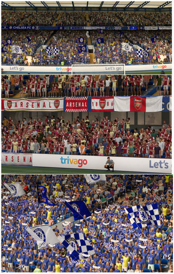
Figure 1.
Crowd agents sharing the same animation but users might not greatly notice the sharing because the postures of the agents are different at each time point.
3.3. Current Limitations and Requirements
In recent years, the requirements for animation systems have evolved significantly [15], and the current documented implementations of the crowd systems described above are not able to meet these requirements. A collection of these requirements are defined below:
- Animation state machines instead of simple animation clips are becoming more common, with transitions among clips decided by a decision-making layer on the simulation side.
- Generalized two-dimensional blending depending on input parameters fed in at runtime.
- Animation clips can be authored with event tags such that when the playback reaches certain points on their timeline it triggers an event to the simulation side (e.g., plays a sound when an agent is hit at the correct timing).
- Partial skeleton blends depending on the state and animation layering: agents should be able to play multiple animations simultaneously (e.g., walking and hand waving only when observing the human user).
Since animation data were previously stored statically in a GPU texture for performance reasons, the above requirements could not be satisfied because the input feed and decisions made dynamically by the simulation side could only have a limited effect on the agent’s animations (i.e., the system could only allow simple blending between existing poses). In addition, storing the entire animation dataset on the GPU would significantly limit the number of possible animations that a crowd system could use. These two main limitations were addressed in [1] by using a mixed model between streaming animations data from CPU to the GPU and storing only a part of the animation dataset on the GPU memory (Figure 2). Their definition of storing poses on both CPU and the GPU is shown in Figure 3).
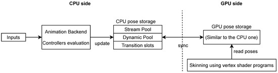
Figure 2.
Overview of the CPU–GPU data flow for each frame addressed in [1].
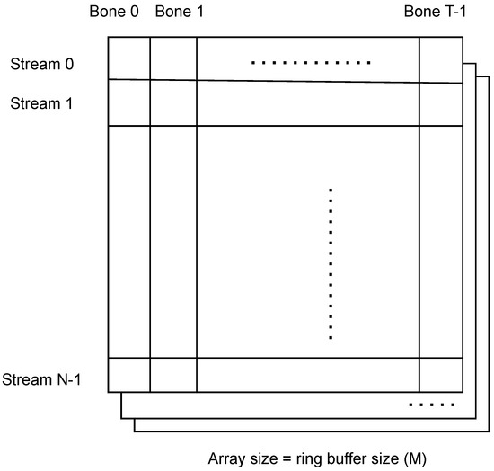
Figure 3.
The pose history storage representation for both CPU and the GPU in previous work, with N—-the pooled animations, T—the maximum number of bones of all skeletons, and M slices—the maximum offset in frames. Each row of a slice represents a pose buffer and has sufficient capacity to store all skeletons used in the animation system.
At each frame F, for each streamed animation (S), the root controller associated with these animations is evaluated and writes data on a slice (array index) , on row . All these updates (as well as the poses of the unique and transition slots) are packed and sent to the GPU to maintain both pose stores in sync. The GPU needs the pose data for skinning purposes, since, for each vertex, the shader knows the global animation index (unified index system between streamed unique pools and transition slots) and the offset (valid in the case of streamed animations) and fetches the transformation matrix associated with the bones affecting that vertex.
The CPU side requires the same pose data due to the blending system explained in the next section. There are a few drawbacks of their implementation that significantly increased the memory footprint required. First, the pose storage was duplicated, mainly to support the transition slots. To support multiple skeletons (i.e., with different numbers of bones), the texture width size was set to the maximum among all skeleton sizes, resulting in unused memory when the variance between skeleton sizes was large. To support different offsets per animation stream, many of the texture slices could contain unused rows for animations that require less offset than the maximum.
In this paper, we are reusing the same requirements of dynamic input support and the strategy of holding partial animation data, but we improve this strategy to allow different skeletons to be used more efficiently (Section 4) and remove the duplicated memory required for the pose data structure on the CPU side by using GPU-only blending. The transition slots are completely removed in our new implementation.
3.4. Animation Controllers
The concept of the animation controller used in our framework is similar to the one presented in [1,15,25]. Typically, animation framework systems have a visual editor that allows the user to customize a controller and its internal evaluation operation. A basic use case is to define an animation controller that represents a single motion clip (not a child). Its evaluation provides pose data at the specified time parameter and could include decoding the animation clip data and performing interpolations between keyframes. Controllers can be represented as trees of operations. Evaluating a controller at time t, means recursively evaluating its children nodes and then combining the pose buffer from each child into its own pose buffer—the one attached to the animation that it is controlling, as is shown in Listing 1.
Listing 1.
Pseudocode for evaluating a controller.
- ControllerA::Evaluate(t)
- ChildrenList = {Ci |
- Ci is the i{th} child controller}
- Evaluate(t, ChildrenList)
- PA = Combine( PCi).
Another basic use case is to use a controller to blend between two animations (A and B). Such a controller can have two child controllers: and . As shown in Equation (2), the resulting pose of evaluating is an interpolation between the resulting poses of its two children by the variable s (normalized blend time; 0 means start, 1 end).
Complex trees of controllers can be customized for an animation. For instance, one could use a blend mask to consider only parts of the bones from each child controller. Equation (3) represents a controller evaluation with three children: from it takes only the pose for the head, gives the pose for the arms, and finally provides the pose for the legs of a biped character. A blend mask is defined as an array of values and has the same length as the pose array. The ∗ product between the two cancels the pose for the bones that are not interesting for the mask (e.g., only the set of bones is considered).
Another example of a common animation controller is a state machines [15], where the transitions are generated/evaluated by triggers/values set by the simulation side (e.g., an AI system). If the above controllers can be implemented on the GPU side using shaders to optimize performance, the ideal running place for the controller representing a state machine would be the CPU due to the tight communication between simulations and online data that is usually provided on the CPU side.
Another motivation for running controllers on the CPU side instead of the GPU is the use case of authoring motion clips with certain events on their timeline that need to be communicated back to the CPU side. Frequent communication between the GPU and CPU would cause serious performance issues that could negate the benefits of performing the mathematical operations in shader programs. Modern animation frameworks usually allow users to customize their own controllers and integrate them into the animation system using a provided editor.
4. Crowd Animation in Our Framework
This section presents the terminology used and the implementation details of our new animation framework with the features promised in Section 1.
4.1. Animation Streams
As stated in Section 3.2, a visual animating mesh definition can be represented as a pair AnimDef = (Skeleton, Skin mesh).
In our framework, an animation stream A is a tuple defined as: . The pose buffer represents the transformation data for each bone at the current time of animation: = transform of the ith bone of the animation A’s skeleton. represents the root animation controller of animation A. The last parameter is a circular buffer that stores the history of the last values evaluated for .
The parameter is user configurable and represents the maximum number of frames to be stored in the buffer (many applications typically consider sampling animation poses at 30 or 60 Hz). Each animation stream has a state ( parameter), which can be one of the two: or . When the state is active, its animation controller is updated by writing the pose output in and then copying it to the current head of the pose history buffer .
The user input for the animation system can be defined as a tuple: . The is a static array created at initialization that contains streams of animations that can be shared among multiple agents. Suppose three types of animation streams have been defined: one playing a walk controller animation, another one playing an idle, and one for a specific celebration. Agents can then share these three animation streams, reducing the resources required at runtime in comparison with having a different animation stream for each agent.
A random offset in the assigned animation stream pose history space is assigned for each individual, to make them look different even if they use the same processed data (more details are given in the next section). During initialization, the user can specify the default state of each animation stream in the . This can have a significant impact on performance, as only a few animations streams can be used by default in a crowd simulation, while others are only used temporarily (e.g., motion or idle animations versus celebrations in a soccer game).
is a dynamic array of animation definitions that are not intended to be shared between agents—e.g., users can inject live recorded motions at runtime that they wish to replicate for agents in the crowd. Its input data type excludes the history pose buffer parameter, since the offsetting system is not needed in this case—the agents assigned to this stream simply read the pose generated in the current frame ().
4.2. Splitting Agent and Animations into Parts
Previous work in the field considered a single skeleton type for the entire crowd (using masks for the individual joints in certain use cases). However, this may require additional memory needed to store the buffers for the history poses (more details in Section 4.5) and also increases the cost of asset creation. As an example, consider the agents of a soccer game, where there may be humans holding a skeleton-based animated scarf or flags in their hands. Using a single skeleton to hold all three types of animations (idle, showing the scarf or flag) requires a huge skeleton.
Animations are also hard to author and imply effort duplication, since, in the worst case, permutations of these animation parts are required. This led to the idea of splitting agent parts in clusters and allowing each cluster to be animated by a different animation stream. For example, a human agent can be split into different parts: head, torso, arms, legs, scarf, andflag. Each of these parts has different meshes, which is an important aspect for the visual diversity of the crowd: Since there is a small set of meshes for each part, permutations of them can create agents that look very different. This idea was already explored in [6] and is extended in this paper for animation purposes.
In the example above, three clusters of parts can be defined by the user: one for the body (including the head, torso, arms, and legs), one for the scarf and another for the flag. These clusters can have different animation streams associated and offsets in their pose buffer. To associate a cluster with an animation stream (either in or ), each has a unique integer index. A special value (e.g., 0 or negative) is used to indicate that no animation is associated. More formally, if each crowd agent has a unique id assigned, then its animation reference can be defined as a tuple:
The first argument in each cluster animation definition is the animation index, while the second argument is the offset in the history of stored poses of that animation stream (). The offset value is relative to the PH’s head (i.e., an offset value of 0 means the head of the circular buffer, while an offset N represents N frames behind the head—).
The purpose of the pose history buffer is to allow multiple agents that share the same animation stream and parts to look different by having different offsets. From a quality perspective, randomization at both the stream index and offset levels significantly reduces the probability that the user will observe agents playing the same animation at any given time. This probability can be controlled by adding more or less animations streams and by changing the parameter . At the implementation level, as mentioned in Section 3.2, the skinned instance is used. The GPU instance buffer for each agent contains the description of among other data.
Each part has a static definition of its parent hook position and transformation, so that when an agent is picking up a scarf, for example, it is correctly synchronized with the arms of its body. The culling of parts is also handled at the shader level, with each agent having a mask of clusters that it should render at any time. For example, if the user wants to hide the cluster representing the scarf for a particular agent, they simply set the mask for the corresponding bit of the cluster in the agent’s GPU instance buffer entry to 0, and then the skinning vertex shader code ignores the mesh.
4.3. Transitions and Time Dilation
At runtime, the user can use the API to request a transition from the currently assigned animation of an agent’s part cluster to another stream loaded in the pools:
As mentioned in Section 4.1, animation streams can be set to one of two states by the user at initialization or . At runtime, transitioning a part to an animation stream that is currently is legal. Since the target animation stream is only starting to create poses in its pose buffer, the part cluster transitioning to it cannot have an animation offset greater than 0 in the first frame (i.e., it points to the current head of the buffer). Consider, as an example, a celebration animation in a soccer crowd. Since there could be many celebration animation streams, it is not wise to play them all from beginning, since they are used only at special times.
Instead, all celebrations start in the state, and when a goal is scored by one side of the game, their supporters body’s parts are transitioned into a randomized celebration stream with a function call to . At the first frame after the transition (blending is discussed in Section 4.4), all parts of these agents have offset 0—which is the new maximum offset () of the animation stream. However, this would severely limit the visual appearance of the crowd if certain groups played the same animation stream frame by frame for the entire duration of the celebration. To solve this issue, we implemented a mechanism called time dilation.
The time dilation system implements a dynamic offset change (either increase or decrease) for a list of agents parts depending on some parameters. The parameters for the system (considering a fixed time frame simulation for simplicity) are: —how many samples per second are taken by the animation system and filled into the pose buffers, —the current maximum offset (in seconds) of animation stream A, and —its maximum new offset. The code in Listing 2 shows what happens when a new animation stream starts and how the offsets of each agent are handled to restore diversity. The same strategy can be applied to dilate offsets even for animation streams that are .
Listing 2.
Starting a new animation stream and updating agent offsets for each simulation frame.
- OnNewAnimStreamStart(A:AStream, timeToDilate)
- // The maximum amount of offset to change
- // per agent and simulation frame
- A.changeRate =
- for each agent part Ag using A
- Ag.offset = 0
- Ag.targetOffset = random(0, A.Mnew)
- OnAnimSystemUpdate()
- …
- for each changing anim stream A
- for each agent part Ag using A
- Ag.offset = min(Ag.offset + A.changeRate, Ag.targetOffset)
- …
Returning to the above example, when the celebration is finished, any agent performing it can eventually return to an idle state animation stream. The animation streams are ref-counted, and if there is no longer an agent part using them and the user’s default was , they go back from to to reduce the runtime resources needed to play their controllers.
4.4. Blending between Animation Streams
The blending methods described in [1], which allowed transitions between animation streams with different offsets, had two limitations that tightly limited the maximum number of agent parts that could simultaneously transition to another animation stream. The transitions were handled as entries in the and handled by running the blending controller on the CPU side. This strategy incurs an additional memory footprint for each transitioning agent and CPU cycle cost.
Our implementation method changed the blending method by performing the computations on the GPU side instead of CPU (i.e., the interpolations are now computed in the skinning vertex shader code) and completely eliminating the extra memory required per transition. When performing transitions between animation streams, the positions of skinned mesh vertices in the respective clusters are found by interpolating between the corresponding poses in the source and target streams (also taking into account the source and target offsets).
Figure 4 and Listing 3 sketch how this works. Note that the information in the pose history buffer of each animation state is synchronized between the CPU and GPU (more details are in Section 4.5). Pose data changes from frame to frame considering a fixed offset, since the animation stream head is continuously updated with the stream controller’s output pose.
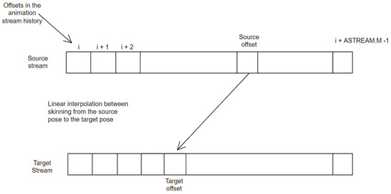
Figure 4.
Interpolation between animation stream poses.
A fixed offset N means that the data should be read N frames behind the current head position in the ring buffer. If you take this into account, the blend is performed between two animation streams, both of which are updated. It starts with the source animation stream and the original offset, and ends up with the target animation stream and the target offset.
Listing 3.
Pseudocode that shows the internal blending in the skinning vertex shader code to compute the vertex position of any given agent’s mesh bind pose vertex and animation data.
- VertexPos skinVertex(VertexPos inputVertex, agentId, clusterId)
- data = instanceBuffer[agentId, clusterId]
- // Get the vertex skinned according to the source animation
- VertexPos srcVertex = skinVertex(data.srcAnimStream, data.srcOffset)
- if agentData.isBlending == 0
- return srcVertex
- // If its blending, then consider the destination animation too
- VertexPos targetVertex = skinVertex(data.targetAnimStream,
- data.targetOffset)
- // Get the time elapsed since the transition started
- // Multiply by the inverse blend time
- // to get alpha,
- // the lerp parameter for blending between source and target positions
- timeElapsed = (globalTimer - data.transitionStartTime)
- alpha = clamp(timeElapsed × invBlendTime, 0, 1)
- VertexPos res = lerp(srcVertex, targetVertex, alpha);
- return res
4.5. Memory Layout and the CPU–GPU Data Flow
This data flow is shown in Figure 5. The block is responsible for collecting inputs for the animation system (e.g., decision-making systems that derive states for animation controllers that execute state machines or live recorded motions that provide online data). The component is responsible for executing the animation controllers. The data flow has the same advantages as those presented in [1], i.e., it can use inputs from lower decision layers; however, using the blending strategy defined in Section 4.4 eliminates the need for the duplicate pose history buffer for each animation stream on CPU.
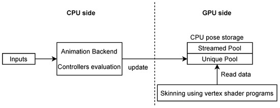
Figure 5.
The new overview of the CPU–GPU data flow on each frame.
The data needed for the shader now resides only on the GPU side. Figure 6 shows how this can look. The and the are on separate memory locations because they have different requirements. The is organized in ordered blocks of frames (starting at 0 up to the maximum frame of all animation streams, regardless of their default state). For each frame block index I, the animations streams that support at least I frames as their maximum offset have entries inside.
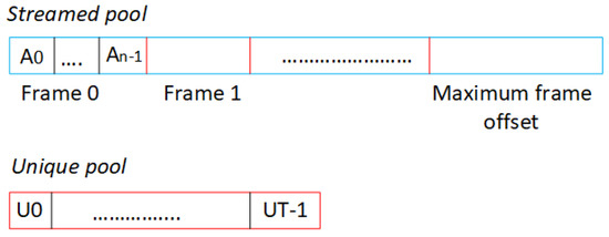
Figure 6.
The pose data structure on the GPU side.
An entry in an animation stream is a block with a matrix for all animated bones of its skeleton, representing their transformation on the parent frame index. At initialization, a lookup table is created to find the memory location in where a pair must be written/read. By using the blending method defined in Section 4.4 and the lookup table, our framework can support different skeletons and offsets per animation stream.
Since the slots for the are dynamically selected at runtime based on the user’s request, each animation stream must have sufficient entries to support the skeleton with the highest number of bones. At each simulation frame index F, for each animation stream in (S), the root controller associated with that animation is evaluated and writes data to . All of these updates (plus the current pose of the running animation streams in ) are packed and sent to the GPU to update its pose storage data structure.
4.6. Skinning Shader and Custom Animations per Agent
The GPU requires the pose data structure (Figure 6) for skinning purposes. For each vertex, the skinning shader knows the animation stream index and frame offset and fetches the transformation matrix associated with the bones that affect that vertex.
Sharing the same animation stream across a set of agents does not necessarily mean that the individual agents cannot have procedurally/per bone customized animations. This is a topic that has not been addressed in previous work, and corresponding requirements frequently appear in various applications. A concrete example is the requirement from our framework usage was to make a soccer crowd’s agents turn their heads at different targets during a match (e.g., one side goal, the referee, etc.).
One solution that works in this case is to mark the bones so that they are overridden by a custom vertex shader code authored by the user. The vertices that depend on these bones will call the custom user code instead of reading the animation data from the pose buffer of the assigned animation stream. In the example above, the head mesh bones were marked as overridden by user code, which, in turn, rotated the dependent vertices around the Y axis, aligning the head of these agents with a target specified in the agents’ instance buffer. Examples of crowd agents pointing their heads at various targets during a match, such as players in action or players in celebration, can be seen in Figure 7.
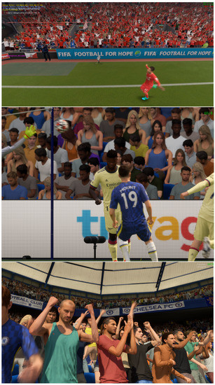
Figure 7.
Crowd agents pointing their heads to the players in celebration/action.
5. Evaluation
The animation techniques described in this paper are implemented in the internal engine of a video game company and are reused for several games published (FIFA game—FIFA 22 by Electronic Arts) or in progress. The evaluation of the proposed method is based on a crowd of approximately 65,000 agents distributed in a soccer stadium representing different categories of soccer fans (home, away, or ultras).
Their animations included: scoring celebrations, disappointed reactions, anticipation of goals, disagreement with referee or player decisions, walking around chairs, etc. Each agent mesh was split into four clusters. Approximately 1024 animations were defined in , each with a maximum offset of 20 to 120 frames. The skeletons used for each part cluster also had different numbers of bones: human skeletons consisted of 82 bones, the flag had 25 bones, and the scarf had 24 bones.
First, we are interested in the memory saved by eliminating the transition slots, and the optimizations made to efficiently support the different number of bones and offsets. If U denotes the maximum size of , is the maximum number of bones of all skeletons used, S is the size of , and T is the maximum number of transitions allowed on the same frame (note, that this parameter is potentially unbounded in our new framework, but left here for comparison purposes) and since each bone in our framework is represented by a matrix of single precision floating-point number (48 bytes total per bone), the Equations (4)–(6) show the analytical memory cost in bytes and the differences between the previous model in [1] and the one described in this paper.
Speaking in terms of concrete data and considering for our use case, we found that our new method saves ≈293 MB of memory.
The CPU–GPU bandwidth problem indicated in [1] has been further improved, as the transition slots have disappeared and the blending is done entirely with animation stream poses from the storage. The only data that is now moved between CPU and GPU to maintain memory is animation streams that are running and require dynamic input from the simulation side. However, the main advantage of processing blending on the GPU side is performance.
Since interpolations are friendly for GPU cores and branch divergence is low, and since most consecutive vertices of a mesh fall into the same branch (Listing 3), we were able to fit ≈40-times more transitions in the same amount of time than in [1] with the same time budget. More specifically, if the hard limit on the number of parts of agents that can simultaneously transition to another animation stream within a budget of 3 milliseconds per frame was ≈128, our new use-case target, which is solved by the methods presented in this paper, is to significantly increase the maximum number of transitions using the same computational resources as the budget. Our new target is 4096 of simultaneous transitions within a 3 ms budget.
By splitting the agents into parts, the time required to produce assets has been almost halved in our case. The cost of creating skeletons and animations for permutations of simple human agents, humans with a scarf, or humans with flags was simply replaced by the cost of creating a skeleton and a set of animations for each part. This cost reduction can be even more significant depending on the number of valid parts permutations.
The time-dilation feature added in our version evaluation depends significantly on the use cases of the crowd’s system. In our case, we only had idle and walking animations, which should be in the state by default. Many other animation streams, such as celebration, waving flags, or a scarf were supposed to run only at certain points in a match.
Without the time-dilation feature, the only options were to run all animation streams from the beginning (but this was not feasible in terms of resources needed), to accept that all agents have offset 0 for the entire duration of these animations (also not feasible from a quality point of view), or to use unique characters from the as mentioned in [1]. However, the hard limit in this last case could be around 128 agents parts because of the CPU cost of running the animation controllers. Thus, the time dilation feature can potentially help increase performance and/or quality in crowd systems where the requirements are to have many animation streams that do not play from the beginning, and/or a large number of agents that transition to an animation stream that is by default.
6. Conclusions and Future Work
We presented certain techniques to increase the performance, diversity, and usability of animation systems in applications that use crowds of agents. The paper first presented the state of the art and then showed the improvements of our new framework using a collection of use cases we had that could potentially occur in many other applications. The paper presented an improved blending technique between animation streams that supports different offsets and runs entirely on the GPU side, requiring no additional memory other than the source and target animation streams. This method has significantly reduced the runtime resource requirements for both processing and storing data.
Splitting agents into parts has the potential to save significant costs in creating assets for skeletons and animation data, as the method described no longer requires permutations of assets to be created. Time dilation can also help increase the performance or number of assets that can be activated at any time in a crowd system, as there is no longer a concern that agents can transition to an animation stream that has no poses in the history buffer—by the time the buffer fills, agents will dynamically change their offsets and quickly create diversity again.
From the point of view of visual quality, we believe that characters who are very close to the camera, must be rendered and animated with full detail and state-of-the-art techniques in order to achieve the best possible visual quality. The methods described in this work are best suited for background characters in general—crowds with a large number of people that cannot be animated efficiently with previous techniques.
We plan to investigate other things, such as the dynamic level of detail of animation to optimize the controllers played on the CPU side and techniques for transitioning between skeletal and cage/impostor animations. The intention is to make this framework generic and open source so that the community can contribute to it in the future. Crowd systems may play an important role in tomorrow’s applications, including simulation software, VR, or video games.
Author Contributions
Coceptualization, C.P.; software, C.P. and M.P.; validation, C.P. and M.P.; investigation, C.P. and M.P.; writing original draft preparation, C.P.; writing review and editing, C.P. and M.P. All authors have read and agreed to the published version of the manuscript.
Funding
This work was supported by a grant of Ministry of Research, Innovation and Digitalization, Romania, Grant no 56PTE/2020, MASSA.
Institutional Review Board Statement
Not applicable.
Informed Consent Statement
Not applicable.
Data Availability Statement
Data is contained within the article.
Conflicts of Interest
The authors declare no conflict of interest.
References
- Paduraru, C. Increasing diversity and usability of crowd animation systems. In Proceedings of the 26th International Conferences in Central Europe on Computer Graphics, Visualization and Computer Vision (WSCG), Plzen, Czech Republic, 29 May–2 June 2017. [Google Scholar]
- Ryder, G.; Day, A.M. Survey of Real-Time Rendering Techniques for Crowds. Comput. Graph. Forum 2005, 24, 203–215. [Google Scholar] [CrossRef]
- Beacco, A.; Pelechano, N. A Survey of Real-Time Crowd Rendering. Comput. Graph. Forum 2016, 35, 32–50. [Google Scholar] [CrossRef] [Green Version]
- Jeremy, S.; Barczak, J.; Oat, C.; Tatarchuk, N. March of the Froblins: Simulation and rendering massive crowds of intelligent and detailed creatures on GPU. In Proceedings of the ACM SIGGRAPH 2008 Games, Los Angeles, CA, USA, 11–15 August 2008; pp. 52–101. [Google Scholar]
- Rudomin, I.; Millan, E.; Hernandez, Z. Fragment shaders for agent animation using finite state machines. Simul. Model. Pract. Theory 2005, 13, 741–751. [Google Scholar] [CrossRef]
- Nguyen, H. Animated Crowd Rendering. In GPU Gems 3; Addison-Wesley: Boston, MA, USA, 2007; Chapter 2; pp. 39–52. [Google Scholar]
- Beacco, A.; Pelechano, N. CAVAST: The Crowd Animation, Visalisation, and Simulation Testbed. In Proceedings of the Spanish Computer Graphics Conference (CEIG), Zaragoza, Spain, 2–4 July 2014; pp. 1–10. [Google Scholar]
- Tecchia, F.; Chrysanthou, Y. Real-time rendering of densely populated urban environments. In Proceedings of the Eurographics Workshop on Rendering Techniques, Brno, Czech Republic, 26–28 June 2000; pp. 83–88. [Google Scholar]
- Millan, E.; Rudomin, I. Impostors, pseudo-instancing and image maps for GPU crowd rendering. Int. J. Virtual Real. 2007, 6, 35–44. [Google Scholar]
- Kim, J.; Seol, Y.; Kwon, T.; Lee, J. Interactive manipulation of large-scale crowd animation. ACM Trans. Graph. (TOG) 2014, 33, 1–10. [Google Scholar] [CrossRef]
- Witkin, A.; Popovic, Z. Motion warping. In Proceedings of the 22nd Annual Conference on Computer Graphics and Interactive Techniques, Los Angeles, CA, USA, 6–11 August 1995; pp. 105–108. [Google Scholar]
- Lucas, K.; Michael, G.; Pighin, F. Motion graphs. ACM Trans. Graph. (TOG) 2002, 21, 473–482. [Google Scholar]
- Lucas, K.; Michael, G. Flexible Automatic Motion Blending with Registration Curves. In Proceedings of the ACM SIGGRAPH, Eurographics Symposium on Computer Animation, San Diego, CA, USA, 26–27 July 2003; Volume 21, pp. 214–224. [Google Scholar]
- Brand, M.; Hertzmann, A. Style machines. In Proceedings of the 27th Annual Conference on Computer Graphics and Interactive Techniques, San Antonio, TX, USA, 23–26 July 2014; pp. 543–647. [Google Scholar]
- Gregory, J. Chapter 11: Animation Systems. In Game Engine Architecture, 2nd ed.; CRC Press: Boca Raton, FL, USA, 2014. [Google Scholar]
- Arikan, O. Compression of Motion Capture Databases. ACM Trans. Graph. 2006, 25, 890–897. [Google Scholar] [CrossRef]
- Hijiri, T.; Nishitani, K.; Cornish, T.; Naka, T.; Asahara, S. A spatial hierarchical compression method for 3D streaming animation. In Proceedings of the Fifth Symposium on Virtual Reality Modeling Language Web3D-VRML ACM, Monterey, CA, USA, 20–24 February 2000; pp. 95–101. [Google Scholar]
- Sattler, M.; Sarlette, R.; Klein, R. Simple and efficient compression of animation sequences. In Proceedings of the Eurographics Symposium on Computer Animation, Los Angeles, CA, USA, 29–31 July 2005; pp. 209–217. [Google Scholar]
- Kavan, L.; Collins, S.; Zara, J.; O’Sullivan, C. Skinning with dual quaternions. In Proceedings of the Symposium on Interactive 3D Graphics (SI3D), Seattle, WA, USA, 30 April–2 May 2007; pp. 39–46. [Google Scholar]
- Pelechano, N.; Allbecky, J.M. Motion warping. In Proceedings of the IEEE Virtual Humans and Crowds for Immersive Environments (VHCIE), Greenville, SC, USA, 20 March 2016; pp. 17–21. [Google Scholar]
- Kavan, L.; Sloan, P.P.; O’Sullivan, C. Fast and Efficient Skinning of Animated Meshes. Comput. Graph. Forum 2010, 29, 327–336. [Google Scholar] [CrossRef] [Green Version]
- Vasilakis, A.A.; Fudos, I.; Antonopoulos, G. PPS: Pose-to-Pose Skinning of Animated Meshes. In Proceedings of the 33rd Computer Graphics International, Heraklion, Greece, 28 June–1 July 2016; pp. 53–56. [Google Scholar] [CrossRef]
- Moutafidou, A.; Toulatzis, V.; Fudos, I. Temporal Parameter-Free Deep Skinning of Animated Meshes. In Proceedings of the Computer Graphics International Conference, Online, 6–10 September 2021. [Google Scholar] [CrossRef]
- Magnenat-Thalmann, N.; Laperrire, R.; Thalmann, D.; Montreal, U.D. Joint-dependent local deformations for hand animation and object grasping. In Proceedings of the Graphics Interface’88, Edmonton, AB, Canada, 6–10 June 1988; pp. 26–33. [Google Scholar]
- Unity. Unity Engine Manual—Animation Section. Available online: https://docs.unity3d.com/Manual/AnimationSection.html (accessed on 10 June 2021).
Publisher’s Note: MDPI stays neutral with regard to jurisdictional claims in published maps and institutional affiliations. |
© 2022 by the authors. Licensee MDPI, Basel, Switzerland. This article is an open access article distributed under the terms and conditions of the Creative Commons Attribution (CC BY) license (https://creativecommons.org/licenses/by/4.0/).