Article

Intelligent Robotic Welding Based on a Computer Vision Technology Approach

by
Nazar Kais AL-Karkhi
1,
Wisam T. Abbood
1,
Enas A. Khalid
1,
Adnan Naji Jameel Al-Tamimi
2,
Ali A. Kudhair
3 and
Oday Ibraheem Abdullah
4,5,6,*
1
Automated Manufacturing Engineering Department, University of Baghdad, Baghdad 10066, Iraq
2
College of Technical Engineering, Al-Farahidi University, Baghdad 10001, Iraq
3
Department of Reconstruction and Projects, Ministry of Higher Education and Scientific Research, Baghdad 10065, Iraq
4
Energy Engineering Department, University of Baghdad, Baghdad 10071, Iraq
5
Department of Mechanics, Al-Farabi Kazakh National University, Almaty 050040, Kazakhstan
6
System Technologies and Engineering Design Methodology, Hamburg University of Technology, 21073 Hamburg, Germany
*
Author to whom correspondence should be addressed.
Computers 2022, 11(11), 155; https://doi.org/10.3390/computers11110155
Submission received: 9 September 2022 / Revised: 20 October 2022 / Accepted: 27 October 2022 / Published: 29 October 2022
(This article belongs to the Special Issue Multimodal Pattern Recognition of Social Signals in HCI)

Abstract

:
Robots have become an essential part of modern industries in welding departments to increase the accuracy and rate of production. The intelligent detection of welding line edges to start the weld in a proper position is very important. This work introduces a new approach using image processing to detect welding lines by tracking the edges of plates according to the required speed by three degrees of a freedom robotic arm. The two different algorithms achieved in the developed approach are the edge detection and top-hat transformation. An adaptive neuro-fuzzy inference system ANFIS was used to choose the best forward and inverse kinematics of the robot. MIG welding at the end-effector was applied as a tool in this system, and the weld was completed according to the required working conditions and performance. The parts of the system work with compatible and consistent performances, with acceptable accuracy for tracking the line of the welding path.

1. Introduction

Robots have been used to help humans in many businesses, and the most essential duty of robots is achieved in the industry sector. After automation became an important element in modern factories, robots became necessary as part of these automated systems. The execution of a weld face or the upper surface sensor of gas tungsten arc welding (GTAW) contains process estimations and computerization which are dependent on image edge feature recognition [1]. Vision-aided versatile robotic welding is used because its adaptable and robotic welding framework can be controlled by tactile and seam detection [2]. The use of computer vision to determine the conditions of the welding process and the seam dimensions is considered an innovation that will progress the development of independent welding robots. The necessity for specifying weld seam image attributes by improving the calculation of subpixel edge discovery is dependent on Zernike moment weld seam image attributes to enhance the results [3]. The specifying and situating of the start welding position (SWP) is the initial step and one of the main keys to developing the realization of independent robot welding. The coarse-to-fine strategy was created to achieve fruitful autonomous detection and direction of the SWP [4].
An intelligent welding robot is a small part of intelligent welding manufacturing technology framework, coordinated at this stage by intelligent welding advancements, and it was developed with working together positioners [5,6,7]. The adaptive image processing method was utilized for different sorts of weld seams. Composite detecting innovation could diminish the related expenses to accomplish weld seams, rather than using costly gadgets such as laser sensors [8].
The light examination technique is intertwined with infrared and visual images for diagnosing gas metal arc welding (GMAW). The proposed strategy comprises many advantages, e.g., the acquisition, pre-handling, combination, post-preparing, investigation, and recognition of gained images, with an error rate of 0.1 mm [9]. Another technique depends on an artificial neural network, and a continuous vision method utilizes an optic camera to measure the geometry (width and height). The real-time computer vision method aims to obtain the prepared designs and improve the robot’s welding skill (self-training) [10]. An automated robotic welding system consists of a robot, sensor innovations, control frameworks, and artificial intelligence. All these parts are connected to the controller unit, which is considered the brain of the robot. The controller is utilized to program the robot, giving commands to parts of the robot to activate sensors, move, and initiate the welding process to complete the task. The major types of failures in actualizing robots have occurred due to the product that controls the robot [11].
The recognizable proof, discovery, and following weld seam extraction have been generally explored in various manners. However, numerous scientists and researchers have developed various approaches to obtain images from cameras, either by incorporating an external light source or controlling the welding condition to diminish noise. Furthermore, the techniques and methods that have been developed are not entirely valid, and where it is appropriate to apply a particular type of welding, such as butt welding, a system can use a fuzzy-Tracy method to detect 3D seam welding with an accuracy of less than 0.5 mm [12]. A nonlinear enhancement approach was used to improve and increase adjustment accuracy by recognizing and distinguishing the initial, mid, and end of the required path of the weld seams in a straight line of joints of the tempered steel work piece where the average of the welding application errors was ±2 pixel percentages in rows and columns. The pictured work piece was captured by a charge-coupled device (CCD) camera, which was the opposite of the work piece. The weld seam path consistency technique was executed in three phases: (1) pre-handling, (2) decreased area, and (3) distinguishing the weld seam path [13].
Vision sensors and laser vision sensors are generally utilized for determining the positions of the welds and the weld seam paths. It should be taken into consideration that the weld seam geometries and the gaps in any type of weld seam joints will fluctuate. A sensor with multiple types of materials was used to achieve the task [14]. The main objective was to obtain a steady design vision system in real-time for weld images and analyze the image of the edge weld [15]. Most analyses focused on a build-up of viable visual weld detection strategies to discover and treat the issues in multi-layer welding (i.e., spread pass welding detection) for seam tracking and non-destructive testing. The developed strategy should be accurate and include all the effective factors in the welding process to automatically decide the edge between the crease and the base metal in the grayscale picture of the weld at a detection error rate per mm of 0.1–0.4 [16].
Semi-autonomous robotic welding faces various issues, and the most common are the need to correct mistakes in the installation of workpieces, measurements of workpieces, flawed edge planning, and thermal defects during the process. However, there are many significant difficulties, such as the location of the joint edge, following the joint seam, controlling the weld entrance, and estimating the width or profile of the joint [17]. The detecting innovations of the weld pool (three-dimensional vision detection) are an exceptionally dynamic direction for GTAW (gas tungsten arc welding). Moreover, the weld pool characterization of the model and distinguishing parameters of the model should be taken into consideration when, in such cases, intelligent algorithms are primarily used [18].
A review paper [19] summarized many methods using many vision-sensing algorithms for seam tracking in robotic welding systems. The vision sensing methods were active vision sensing (single-line laser, cross-lines laser, and multi-lines laser) and passive vision sensing (grid-lines laser, dot matrix laser, circular laser, welding layer measure, weld pool detection, and swing arc extraction), while the algorithms were the adapted line-fitting algorithms, which include feature points detection and centerline extraction, shape algorithms (between the start, mid, auxiliary, and endpoints), Kalman filter iterated algorithm, optical flow and particle filter algorithm, double-threshold recursive least square method, incremental interpolation algorithm, circle–depth relation algorithm, kernelized correlation filter algorithm, symmetric algorithm of the weld pool around the wire, shape-matching algorithm, kernelized correlation filter algorithm, position error extraction algorithm, absolute interpolation algorithm, and cubic smoothing spline fitting. All of these systems need to be calibrated to objects for the vision sensor, and SWP is used for visual orientation, visual positioning, and 3D coordinate calculation by various image processing algorithms using PID to control the positioning and laser guidance. The active vision sensor was suitable for detecting the position in real-time seam tracking, and the passive vision sensor was typically used with off-programming. Many methods were used to control the moving path of the robot (fuzzy control, trajectory-based control, PID control, iterative learning control, etc.).
In this research, the vision sensor method was used, and it provides the path to the robotic welding directly, without prior programming of the robot, which causes this system work similarly to a worker, but with higher accuracy.

2. Background and Summary

The difference between the robot’s pre-programmed trajectory and the actual and real trajectory makes using sensors essential in automated welding processes for adjusting the welding trajectory [19]. Therefore, the vision sensor method is widely used in this field as it reduces errors and increases accuracy. Various aspects can be concluded from the literature survey about the vision system method. The vision system method includes:
  • A single-line laser, which can detect all welding objects (except T joints) and uses the SVM method feature, which is suitable for all image process algorithms but does not contain enough details about the welds.
  • An active vision sensor, which detects the I, Y grooves, tube sheet, and spot welding, which improves weld identification (speed, accuracy, and electrode resistance are measured), and which is suitable for line tracking, regional center extraction, and direct guiding, with the same features of a single-line laser. These include:
    • A cross-lines laser, which is used for horizontal and vertical weld lines, apertures, and T-joints, as well as detecting the weld variation values, weld line width tracking, aperture, and weld seam tracking using a spatial–temporal Markov model, intensity mapping, and piecewise fitting marking method, all of which have features suitable for T-joints and cross-seam shapes.
    • A multi-lines laser, which is utilized for the butt, lap, and complex curve seams of weld seam tracking that is based on a kernelized correlation filter, and their features used are for tracking weld seam and complicated algorithms.
    • A grid-lines laser used for large V-grooves and surface welds, which is applied for multi-layer and 3D weld construction.
    • A dot matrix laser using real-time 3D weld surfaces based on the slope field of the reflecting laser and has features such as wide weld coverage and situation-specific welding.
    • A circular laser user for all welds—except T-joints— and is suitable for seam tracking and 3D image processing.
    • A welding layer measure used for the welding layer, which as a complex vision system.
  • Passive vision sensors include:
    a
    Weld pool detection, which is used for seam tracking with neural network vision and is suitable for edge detection in real-time detection, but it is affected by the process parameters.
    b
    Swing arc extraction, which controls for penetration in swing arcs with narrow gaps. It is also used for deviation detection using extraction algorithms and local recognition, and it is suitable for considerable groove depths, though it requires an infrared camera.
The previous literature dealt with robotic welding systems using computer vision for seam edge detection and penetration welding. This system can provide the seam welding path and correct it by utilizing artificial intelligence algorithm methods. In this way, the system detects the line welding by image processing using the ANTFIS method to track the welding path for the controlled robot arm, and it corrects this path with a small error range. The algorithm and techniques in this research are used in real-time and are suitable for all types of groove-line welding.

3. The System Description

The system in this work consists of a camera fixed with MIG welding at the end-effector of the 3DOF robot arm. This system aims to connect the results of the image process to control for the forward and reverse kinematics of the robot arms. This control results in employing the ANFIS method to obtain the best result and decrease errors.
The direction field was arranged and improved, prompting constant control, detecting frameworks, prompting seam tracking, and controlling strategies for welding. Most direction estimations of the path of a robot depend on the quantic path addition polynomial. However, it is smarter to opt for a higher-request insertion polynomial to control the yank, generally toward the beginning of the direction, all the more effectively [20]. A vision-based measurement (VBM) method is utilized for edge estimating. A CMOS camera is used with computer vision algorithms and a field programmable gate array board controls the robot for welding [21].
The system uses a CCD camera in computer vision with laser and optical channels to recognize the welding line. The algorithm is executed by image processing to provide the position of the seam welding and the cross-section. The troubles and difficulties generated from welding are the arc light, laser light reflection, and dissipation, and so the distinctive picture procedures must be eliminated. An examination of the various strategies is, nonetheless, conceivable, and the pictures acquired in each examination rely upon the camera, laser, optics, and framework arrangement [22].
Seeking has been completed to recreate the 3DOF robotic arm in a computer-aided design (CAD) condition for welding operation, while its kinematic requirements follow the weld seam path. The automated seam tracking is dependent on inactive monocular vision. The vision provides information to the robotic automated welding framework, permitting quality and productivity gains [23]. A seam tracking algorithm has been proposed for a butt-type weld joint, with changing weld gaps for accuracy in the simultaneous application of weld path positions and weld gaps [24]. Real-time following execution and high precision are structured to be dependent on the morphological picture of a novel seam tracking framework with prepared techniques and a continuous convolution operator tracker (CCOT) object tracking algorithm. The framework comprises a 6DOF welding robot, a line laser sensor, and a high-performance computer [25]. The real-time control of five DOF robot manipulators for weld line tracking uses an ActiveX component and a neural network, and the lighting and position of the camera are imitated. This system uses image processing to detect the centroid between the edges of the plates [26]. The robotic welding vision system is shown in Figure 1.

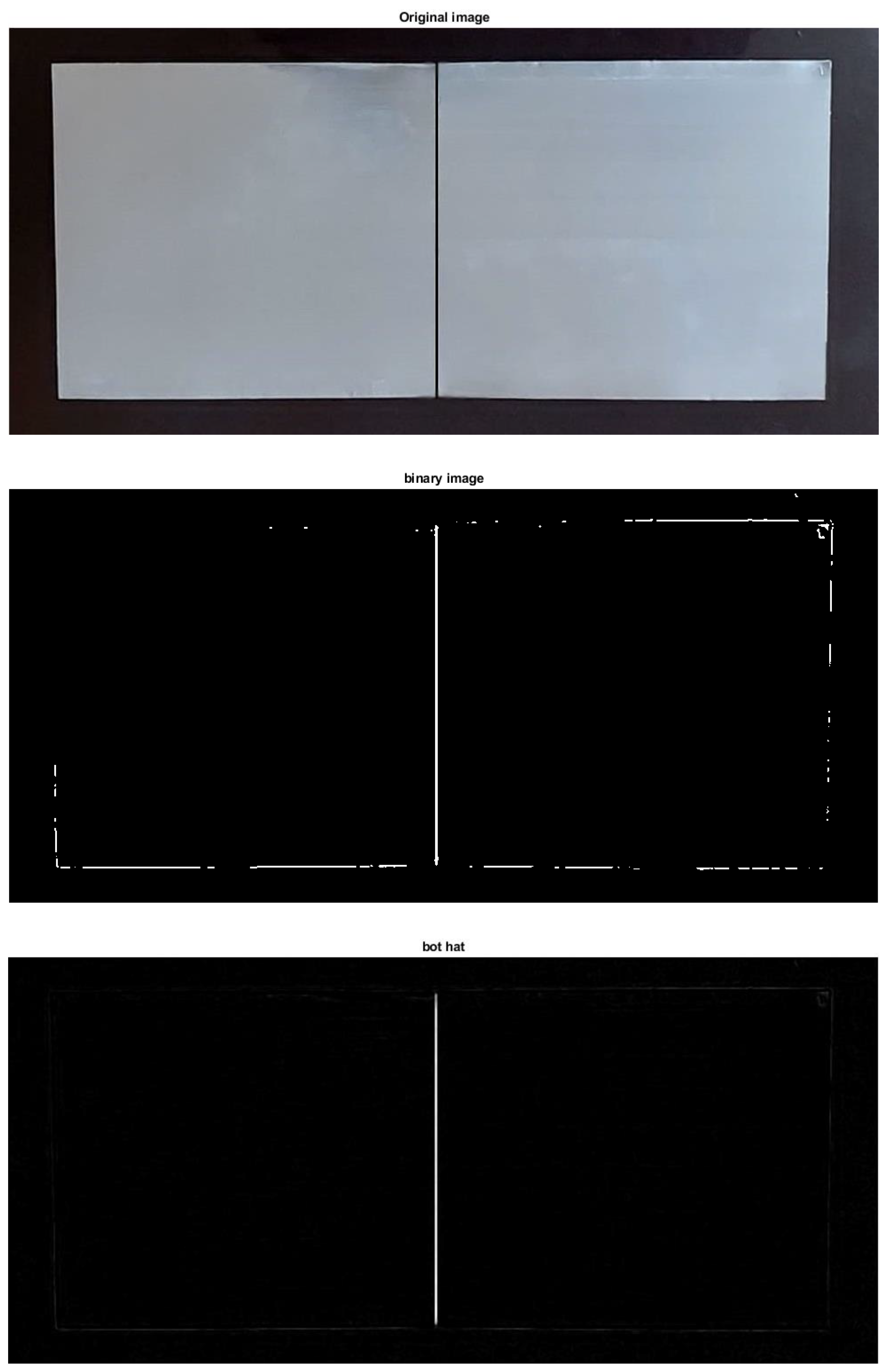
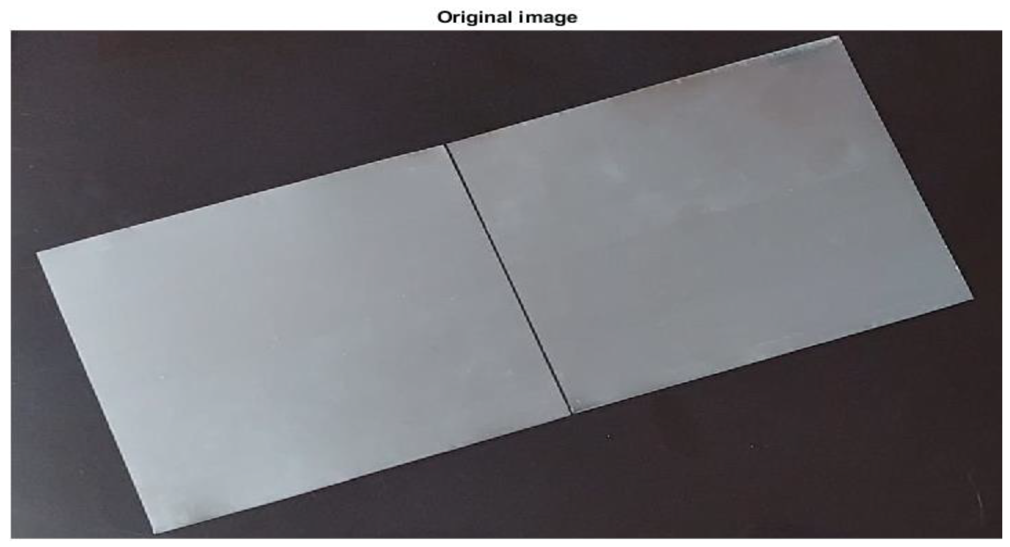
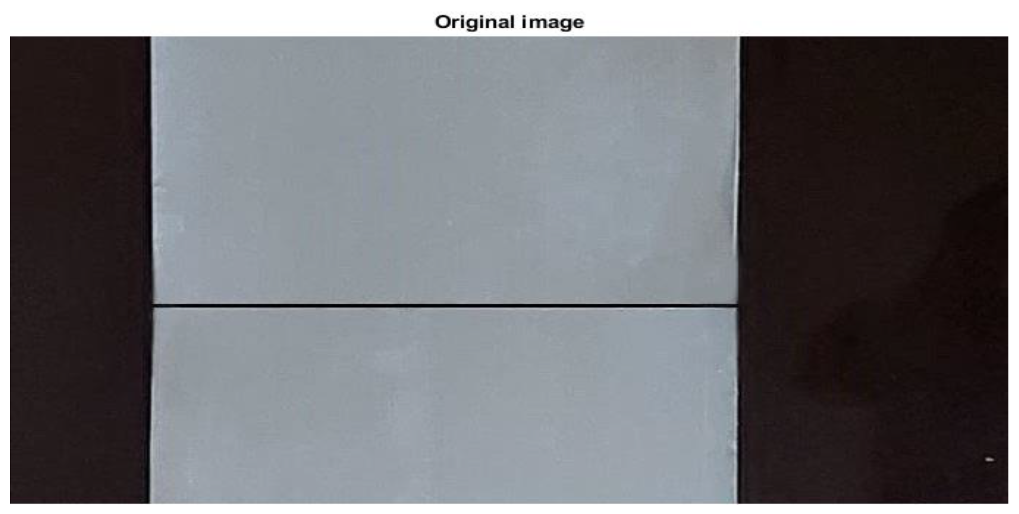
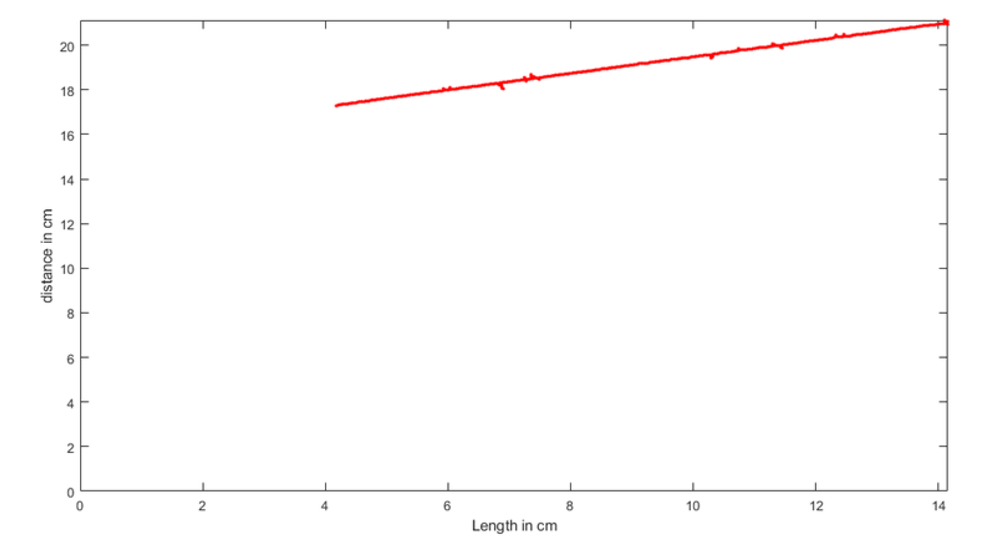
4. Recognition of the Target Line

Several steps were used to find the desired line and obtain points that will provide the path to the robot arm. In the beginning, the camera is fixed above the plates and captures the image. The distance between the plates and the camera is calibrated to determine a real dimension of the captured image. The target line in the image must be the same length relative to the real line. The coordinate of the target line will be detected by assuming that the field of vision for the camera is in plane form. This will create an easy procedure to obtain the coordinate near the real dimension. The origin point at the plane image of the camera will be the origin point at the plane of the target line. The camera used in this system is a Canyon, with a CMOS sensor, 1.3 Mpx resolution, and a 30 fps maximum frame rate. Figure 2 shows the planes of the camera and the target line.
The system vision, including the camera and PC computer, is described as follows [27]:
K x y z = u v λ
and it can be rewritten as:
K x = u K y = v K z = λ
where ( u , v ) represent the pixel coordinates and λ is the distance behind the image plane.
From Equation (2) we can obtain Equation (3), where K ,   u ,   and   v can be calculated as:
K   =   λ z ,   u = λ x z   a n d   v = λ y z
The calibration steps for finding the intrinsic and extrinsic camera parameters are as follows:
  • The calibration object is rectangular in shape, and its length and width are measured and represented by dx and dy, respectively.
  • The camera and the calibration object are placed on a flat floor in a parallel position in a level manner. The calibration object should be accurately placed in the center of the camera’s vision.
  • The distance between the calibration object and the camera is calculated and denoted by dz.
  • A picture is taken to verify the installation’s correctness by ensuring that the edges of the calibration object are aligned with the row and column of the image.
  • The length and width of the calibration object (dx and dy) are calculated in pixels.
The canny edge detection algorithm, convolution-based technique, and top-hat transform methods are implemented to detect the desired line of the weld. The canny strategy activity comprises six fundamental advances [28]:
Stage 1: A one-dimensional smooth Gaussian for effectiveness is applied
2 D G = 1 D G × 1 D G
where D is the dimension and G is the Gaussian:
G σ x , y = 1 2 π σ 2 e x 2 + y 2 2 σ 2 = 1 2 π σ e x 2 2 σ 2 × 1 2 π σ e y 2 2 σ 2
Stage 2: Gaussian derivation is used to register the inclination for the picture (I):
G × I
Stage 3: The magnitude is calculated as:
G × I
Stage 4: The direction at every pixel is calculated as:
n ¯ = G × I G × I
Stage 5: Non-most extreme concealment occurs where the inclination extent is at its greatest along the course of the angle.
Stage 6: Hysteresis thresholding (L and H) utilizes two limits (low and high), called two-fold thresholding.
The wide line intersection of the two edges of the plates and its orientation are detected using a convolution-based technique. In addition, this method is used to distinguish between the desired wide lines and the other edge lines. The general equations Equations (9)–(15) of the convolution-based technique are [29]:
g x , y = k f x , y = d x = a a d y = b b k d x , d y f x + d x , y + d y
where g(x, y) is the result of the image, f(x, y) is the capturing image, k is the convolution-based technique, and the element of the convolution-based technique is considered by a d x a and b d y b .
There are two basic operations, the dilation and erosion of image f (x, y), which use the structuring element B (u, v). They can be defined as:
f B x , y = max u , v f x u , y v + B u , v
f B x , y = min u , v f x + u , y + v B u , v
where B (u, v) and f(x, y) are the original images.
Opening ◯ and closing ● denote dilation and erosion, respectively, as:
f B = f B B
f B = f B B
Top-hat transform is a method used to extract small elements and details from the image, also called digital image processing [30,31,32]. The top-hat transform is applied in many fields, such as industrial and medical fields [33,34]. The image segmentation was improved by using the top-hat transform method to detect the object compared to the background in a given image [35]. Developing a multiscale top-hat sensor achieves good enhancement of the results [36]. Further, it can detect multiple line features by the analysis of the top-hat transform with different directions [37,38].
The white top-hat transform (WTH) and black top-hat transform (BTH), or bottom-hat, are defined as:
W T H x , y = f x , y f B x , y
B T H x , y = f B x , y f x , y
The welding tool tracks the middle line between the faying surfaces of the welded plates. Many researchers are interested in image processing and real-time automated robotics [39,40,41,42,43,44].
The coordinates of the Hough line were found to identify the path of the weld tool robot at the plane of the plates. The robot’s base was this plane’s original point (0,0), and the robot tracked the points of the line detected at a fixed speed.

5. Robotic Forward and Inverse Kinematics

The control of the forward movements of the end-effector of the robot is obtained by the coordinate’s line detection as a path planer using an edge detection algorithm, as mentioned before. The general forward equations of the 3DOF arm are [45]:
T k 1 k = C θ k C α k S θ k S α k S θ k a k C θ k S θ k C α k C θ k S α k C θ k a k S θ k 0 S α k C α k d k 0 0 0 1
The forward kinematics of the base joint and joint 1 for θ1 are:
T b a s e 1 = T 0 1 = C θ 1 0 S θ 1 0 S θ 1 0 C θ 1 0 0 1 0 d 1 0 0 0 1
The forward kinematics of joint 1 and joint 2 for θ2 are:
T 1 2 = C θ 2 S θ 2 0 a 2 C θ 2 S θ 2 C θ 2 0 a 2 S θ 2 0 0 1 0 0 0 0 1
The forward kinematics of joint 2 and joint 3 for θ3 are:
T 2 e n d e f f e c t o r = T 2 3 = C θ 3 S θ 3 0 a 3 C θ 3 S θ 3 C θ 3 0 a 3 S θ 3 0 0 1 0 0 0 0 1
The forward kinematics from the base to the end-effector are:
T b a s e e n d e f f e c t o r = T 0 1 T 1 2 T 2 3 = C θ 1 C θ 2 + θ 3 C θ 1 S θ 2 + θ 3 S θ 1 C θ 1 a 2 C θ 2 + a 3 C θ 2 + θ 3 S θ 1 C θ 2 + θ 3 S θ 1 S θ 2 + θ 3 C θ 1 S θ 1 a 2 C θ 2 + a 3 C θ 2 + θ 3 S θ 2 + θ 3 C θ 2 + θ 3 0 d 1 a 2 S θ 2 a 3 S θ 2 + θ 3 0 0 0 1
The angles of joints θ1, θ2, and θ3 can be calculated by taking the inverse of the kinematics equations, as follows [26]:
θ 1 = A t a n 2 X c , Y c
θ 2 = A t a n 2 r , s A t a n 2 a 2 + a 3 C θ 3 , a 3 C θ 3
where r = X c 2 + Y c 2 and s = Z c d 1 .
θ 3 = A t a n 2 D , ± 1 D 2
where D = X c 2 + Y c 2 + Z c d 1 2 a 2 2 a 3 2 2 a 2 a 3 .
The robotic arm obtains the required line coordinates from the use of image processing on the image captured by the camera. The robot’s end-effector plane is an identifier for the captured image plane of the added flexibility control of the robotic arm manipulation. The control method contains the limit speed that is compatible with the MIG welding tool.
The Z-coordinates of the robot’s end-effector were calculated from the difference of the distance between the camera and the edges of the desired panels and the distance between the camera and the end effector of the robot, as in Equation (20) and as illustrated in Figure 3.
The tool of the robot’s end-effector will have arrived at the coordinate (X, Y, and Z) of the detection line, where Z is defended and XY is discovered from an image processing algorithm. The forward reverse kinematic is detected by applying a Jacobian transform to move according to the coordinate of the line detection. The Jacobian matrix transform is:
J = x θ 1 x θ 2 x θ 3 y θ 1 y θ 2 y θ 3 z θ 1 z θ 2 z θ 3

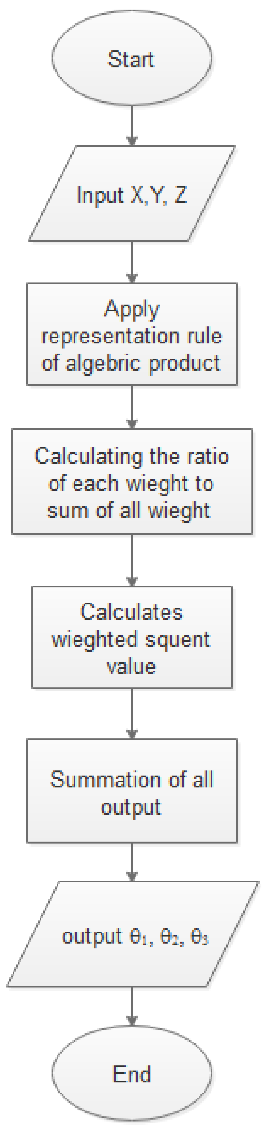
6. The Robot Forward and Inverse Kinematics Using ANFIS

The end-effector of the robot was moved along the desired coordination line that was discovered and calculated from the collection of algorithms that have been mentioned. However, to make the robot work in an intelligent system and to choose the best movement (forward and reverse), ANFIS (adaptive neuro-fuzzy inference system) was used. The ANFIS method was implemented to reduce the complexity of the analysis and to provide good results compared with mathematical modeling [46]. A simulation for the end-effector’s positions for the 3DOF robot arm manipulation was completed using ANFIS for the accuracy inverse mapping by forwarding kinematics in 2D [47]. The ANFIS method was applied to discrete the error that occurred through the robot kinematic and welding movements. An ANFIS flow chart is illustrated in Figure 4.
The end-effector position (X, Y, and Z) was applied to the algebraic rule to produce the function representation. The ratio of the weights was calculated and their sum was obtained to find the weighted consequent value, and the final θ1, θ2, and θ3 were calculated from the summation of all the outputs.

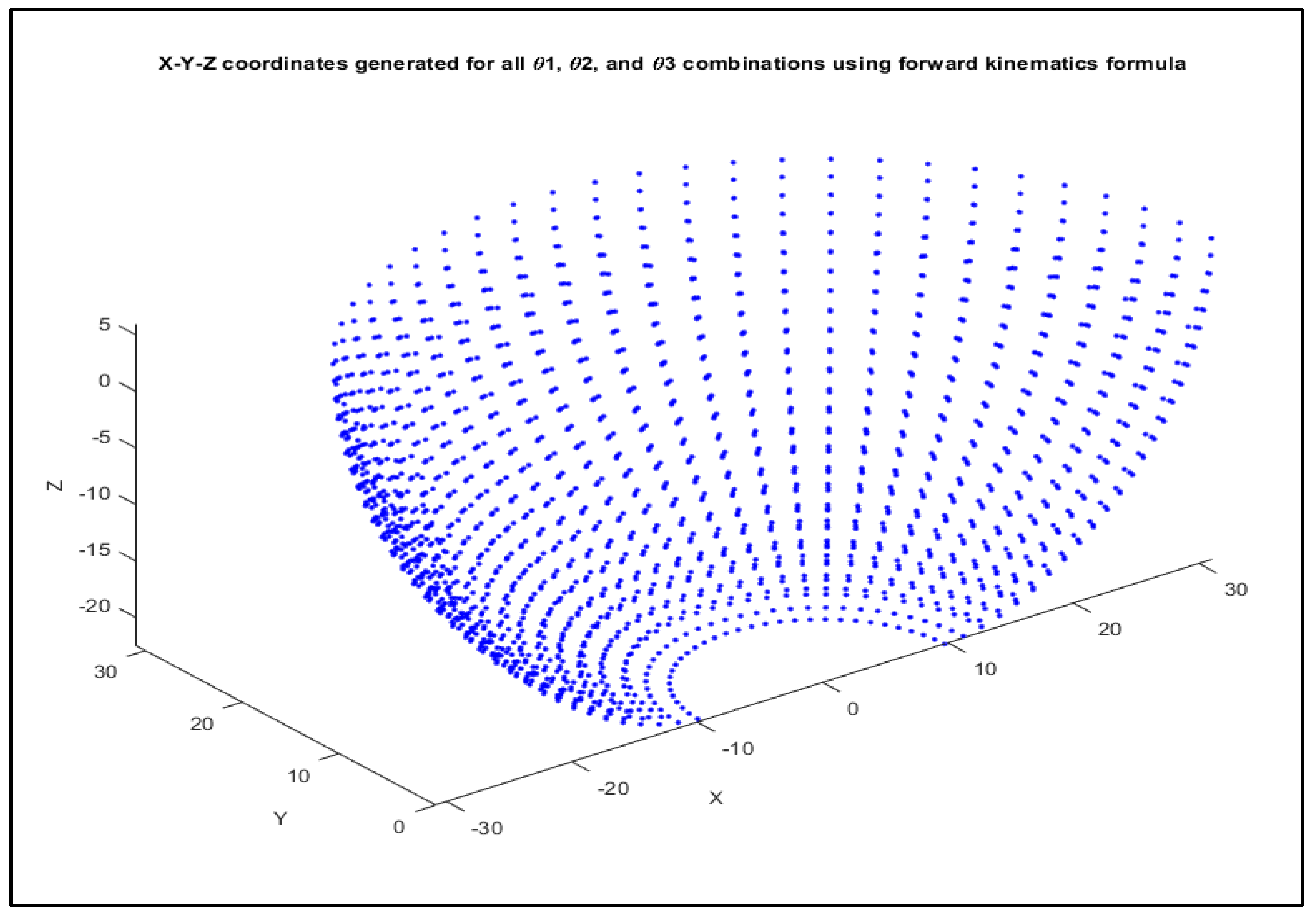
7. The ANFIS Simulation for Robotic Arm Kinematics

The ANFIS simulation for the 3DOF robot moving forward in 3D deduces the movement with which the robotic arm can move all the links at the permissible angles, as shown in Figure 5.
The reverse kinematic is applied, depending on the end-effector position to obtain the reverse joint angles. The ANFIS structure is generated by using the functions and input/output numbers, and then the data are optimized by training and the number of iterations is given shown in Figure 6. Further, the reverse joint angle is plotted and the deferent between the deduced and predicted angles is obtained as shown in Figure 7.

8. Results and Discussions

The results of the vision system from applying the bot-hat method, which detects the junction line between plates in horizontal, vertical, or oblique positions, are shown in Figure 8, Figure 9, Figure 10 and Figure 11. The ANFIS method provides good results for all positions of the junction line. The vision system results realized the robot coordinate point with the end-effector moving according to this point. ANFIS provides the robot arm, predicting the points of the bot-hat between the points discovered. The welding tool is moving at a constant speed, and the gap between the tool and plates is calculated in the program control. The start point and endpoint of the results of the three types bot-hat directions are horizontal, vertical, T-shaped, and oblique. The matrix links of the robot for the start point and endpoint of the horizontal line are shown in Matrices Equations (21) and (22):
M h   S t a r t = 0.0890 0.0000 0.9960 1.1281 0.9960 0.0000 0.0890 12.6208 0.0000 1.0000 0 0.2681 0 0 0 1.0000
M h   E n d = 0.6540 0.0000 0.7565 10.9735 0.7565 0.0000 0.6540 12.6949 0 1.0000 0 0.2620 0 0 0 1.0000
where Mh is the horizontal matrix link. The end-effector of the 3DOF robot begins at the start point in Equation (25), which explains the three links’ movements. Then, the end-effector moves through the horizontal line points to the endpoint, as in Matrix Equation (26), representing the last welding point at the line.
The matrices of the start and end of the vertical line are shown in Equations (27) and (28):
M v   S t a r t = 0.9167 0.0000 0.3996 6.0253 0.8722 0.0000 0.9167 2.6263 0.0000 1.0000 0 0.2683 0 0 0 1.0000
M v   E n d = 0.4272 0.0000 0.9041 6.0931 0.9041 0.0000 0.4272 12.8944 0.0000 1.0000 0 0.2600 0 0 0 1.0000
where Mv is the vertical matrix link. The welding tool moves from the start to the end points through the point discovered by the bot-hat and suggested by the ANFIS method. The oblique line results in Matrices (25) and (26):
M o   S t a r t = 0.3171 0.0000 0.9484 4.1419 0.9484 0.0000 0.3171 12.3883 0.0000 1.0000 0 0.2675 0 0 0 1.0000
M o   E n d = 0.6530 0.0000 0.7574 13.8636 0.3080 0.0000 0.6530 16.0806 0.0000 1.0000 0 0.2609 0 0 0 1.0000
M T   S t a r t = 0.0819 0.0000 0.9966 1.1156 0.9966 0.0000 0.0819 13.5797 0.0000 1.0000 0 0.2647 0 0 0 1.0000
M T   E n d = 0.6481 0 0.7616 11.7386 0.7616 0.0000 0.6481 13.7940 0.0000 1.0000 0 0.2671 0 0 0 1.0000
where Mo is the oblique matrix link. The oblique start and end points line is calculated as in Matrices 29 and 30, which makes the 3-DOF robot move in the oblique position with the detection line with the bot-hat and ANFIS. MT is the T-position matrix link, as shown in Matrices (31) and (32). The red line is presented the junction line plate detection at the three results case (start, and end) points and the (0, 0) points is position of the arm robot. This system’s error value is approximately 0.0083 mm, where the vision system selects one pixel from the pixel line detection and the coordinate’s path is extracted from the one-pixel line detection. The system worked with fixed illumination to obtain the best image. For an industrial environment, the flashlight was solved by applying a median filter for the color-capturing image and then using morphology convolution after converting the filtered image to a binary image to prevent the noise from these flashlights and other noise. The captured image shown in Figure 12 has light flash and noise distribution in all images, where the system can remove this noise and find the target line.

9. Conclusions and Remarks

An intelligent robotic welding system using a vision computer to detect the edges of plates is presented. The ANFIS method is applied to foretell the point’s coordinates between the points of the bot-hat transform that are discovered by the vision system to correct the path if an error occurs. The system succeeded with an error rate of 0.0080 mm for the horizontal lines, 0.0081 mm for the vertical lines, and 0.0083 mm for the oblique lines, which were obtained from the ANFIS control method. The system can detect the line in real-time and the robot move at the line detection. The results were obtained without studying the robotic arm’s changes in speed and acceleration. One of the limitations for the developed approach is the inability to implement it for parallel plates that are vertical to the camera position because the camera did not display and detect this line. It only performed straight-line detection for the robot arm welding. The system needs to be calibrated for the camera’s change in position due to the dimension becoming real. The advantage of this system is the ability to perform real-time edge detection to find the path of the line and welding. The disadvantage is that the system cannot work at any level of illumination because of the error in edge detection. The future work will be to study the results of the system with variations in the speed of the robotic arm, and to development the system for welding any type of lines.

Author Contributions

Conceptualization, N.K.A.-K. and W.T.A.; Formal analysis, methodology, writing original draft, E.A.K.; Formal analysis, resources, A.N.J.A.-T.; Methodology, project administration, A.A.K.; Software, writing- reviewing and editing, O.I.A. All authors have read and agreed to the published version of the manuscript.

Funding

This research received no external funding.

Data Availability Statement

All data has been present in main text.

Conflicts of Interest

The authors declare no conflict of interest.

References

  1. Balfour, C.; Smith, J.S.; Ai-Shamma’a, A.I. A novel edge feature correlation algorithm for real-time computer vision-based molten weld pool measurements. Weld. J. 2006, 85, 1. [Google Scholar]
  2. Agapakis, J.E.; Katz, J.M.; Friedman, J.M.; Epstein, G.N. Vision-aided robotic welding. An approach and a flexible implementation. Int. J. Rob. Res. 1990, 9, 17–34. [Google Scholar] [CrossRef]
  3. Chen, S.B.; Chen, X.Z.; Qiu, T.; Li, J.Q. Acquisition of weld seam dimensional position information for arc welding robot based on vision computing. J. Intell. Robot. Syst. Theory Appl. 2005, 43, 77–97. [Google Scholar] [CrossRef]
  4. Chen, X.Z.; Chen, S.B. The autonomous detection and guiding of start welding position for arc welding robot. Ind. Rob. 2010, 37, 70–78. [Google Scholar] [CrossRef]
  5. Chen, S.B.; Ye, Z.; Fang, G. Intelligentized technologies for welding manufacturing. Mater. Sci. Forum. 2014, 773, 725–731. [Google Scholar] [CrossRef]
  6. Chen, S.-B. On Intelligentized Welding Manufacturing. In Advances in Intelligent Systems and Computing; Springer International Publishing: Cham, Switzerland, 2015; Volume 363, pp. 3–34. [Google Scholar]
  7. Xu, Y.; Lv, N.; Fang, G.; Lin, T.; Chen, H.; Chen, S.; Han, Y. Sensing Technology for Intelligentized Robotic Welding in Arc Welding Processes. In Advances in Intelligent Systems and Computing; Springer International Publishing: Cham, Switzerland, 2015; Volume 363, pp. 411–423. [Google Scholar]
  8. Fidali, M.; Jamrozik, W. Diagnostic method of welding process based on fused infrared and vision images. Infrared Phys. Technol. 2013, 61, 241–253. [Google Scholar] [CrossRef]
  9. Aviles-Viñas, J.F.; Lopez-Juarez, I.; Rios-Cabrera, R. Acquisition of welding skills in industrial robots. Ind. Rob. 2015, 42, 156–166. [Google Scholar] [CrossRef]
  10. Hong, T.S.; Ghobakhloo, M.; Khaksar, W. Robotic Welding Technology. In Comprehensive Materials Processing; Elsevier: Amsterdam, The Netherlands, 2014; Volume 6, pp. 77–99. [Google Scholar]
  11. HShah, N.M.; Sulaiman, M.; Shukor, A.Z.; Jamaluddin, M.H.; Rashid, M.Z.A. A Review Paper on Vision Based Identification, Detection and Tracking of Weld Seams Path in Welding Robot Environment. Mod. Appl. Sci. 2016, 10, 83. [Google Scholar] [CrossRef] [Green Version]
  12. Wang, H.; Lu, X.; Hu, Z.; Li, Y. A vision-based fully-automatic calibration method for hand-eye serial robot. Ind. Rob. 2015, 42, 64–73. [Google Scholar] [CrossRef]
  13. Shah, H.N.M.; Sulaiman, M.; Shukor, A.Z.; Rashid, M.Z.A. Vision based identification and detection of initial, mid and end points of weld seams path in Butt-Welding joint using point detector methods. J. Telecommun. Electron. Comput. Eng. 2016, 8, 57–61. [Google Scholar]
  14. Rout, A.; Deepak, B.B.V.L.; Biswal, B.B. Advances in weld seam tracking techniques for robotic welding: A review. Robot. Comput. Integr. Manuf. 2019, 56, 12–37. [Google Scholar] [CrossRef]
  15. Xu, Y.; Fang, G.; Lv, N.; Chen, S.; Zou, J.J. Computer vision technology for seam tracking in robotic GTAW and GMAW. Robot. Comput. Integr. Manuf. 2015, 32, 25–36. [Google Scholar] [CrossRef]
  16. Wang, X.W. Three-dimensional vision applications in GTAW process modeling and control. Int. J. Adv. Manuf. Technol. 2015, 80, 1601–1611. [Google Scholar] [CrossRef]
  17. Ogbemhe, J.; Mpofu, K. Towards achieving a fully intelligent robotic arc welding: A review. Ind. Rob. 2015, 42, 475–484. [Google Scholar] [CrossRef]
  18. Leonardo, B.Q.; Steffens, C.R.; da Silva Filho, S.C.; Mór, J.L.; Hüttner, V.; Leivas, E.D.; Da Rosa, V.S.; Botelho, S.S. Vision-based system for welding groove measurements for robotic welding applications. In Proceedings of the 2016 IEEE International Conference on Robotics and Automation (ICRA), Stockholm, Sweden, 16–21 May 2016; Volume 2016, pp. 5650–5655. [Google Scholar] [CrossRef]
  19. Lei, T.; Rong, Y.; Wang, H.; Huang, Y.; Li, M. A review of vision-aided robotic welding. Comput. Ind. 2020, 123, 103326. [Google Scholar] [CrossRef]
  20. di Sun, J.; Cao, G.Z.; Huang, S.D.; Chen, K.; Yang, J.J. Welding seam detection and feature point extraction for robotic arc welding using laser-vision. In Proceedings of the 2016 13th International Conference on Ubiquitous Robots and Ambient Intelligence (URAI), Xian, China, 19–22 August 2016; pp. 644–647. [Google Scholar] [CrossRef]
  21. Muhammad, J.; Altun, H.; Abo-Serie, E. Welding seam profiling techniques based on active vision sensing for intelligent robotic welding. Int. J. Adv. Manuf. Technol. 2017, 88, 127–145. [Google Scholar] [CrossRef]
  22. Deepak, B.B.V.L.; Bahubalendruni, R.M.V.A.; Rao, C.A.; Nalini, J. Computer aided weld seam tracking approach. J. Eng. Des. Technol. 2017, 15, 31–43. [Google Scholar] [CrossRef]
  23. Weis, Á.A.; Mor, J.L.; Soares, L.B.; Steffens, C.R.; Drews, P.L., Jr.; de Faria, M.F.; Evald, P.J.; Azzolin, R.Z.; Nelson Filho, D.; Botelho, S.S. Automated seam tracking system based on passive monocular vision for automated linear robotic welding process. In Proceedings of the 2017 IEEE 15th International Conference on Industrial Informatics (INDIN), Emden, Germany, 24–26 July 2017; pp. 305–310. [Google Scholar] [CrossRef]
  24. Rout, A.; Deepak, B.B.V.L.; Biswal, B.B.; Mahanta, G.B.; Gunji, B.M. An optimal image processing method for simultaneous detection of weld seam position and weld gap in robotic arc welding. Int. J. Manuf. Mater. Mech. Eng. 2018, 8, 37–53. [Google Scholar] [CrossRef]
  25. Zou, Y.; Chen, T. Laser vision seam tracking system based on image processing and continuous convolution operator tracker. Opt. Lasers Eng. 2018, 105, 141–149. [Google Scholar] [CrossRef]
  26. Rao, S.H.; Kalaichelvi, V.; Karthikeyan, R. Tracing a weld line using artificial neural networks. Int. J. Netw. Distrib. Comput. 2018, 6, 216–223. [Google Scholar] [CrossRef] [Green Version]
  27. Mark, M.V.; Spong, W. Seth Hutchinson. In Robot Dynamics and Controls; John Wiley & Sons Inc.: Hoboken, NJ, USA, 2020. [Google Scholar]
  28. Pratt, W.K. Digital Image Processing; Wiley-interscience: Hoboken, NJ, USA, 1994; Volume 19. [Google Scholar]
  29. Vernon, D. Machine Vision: Automated Visual Inspection and Robot Vision; Prentice-Hall, Inc.: Hoboken, NJ, USA, 1991. [Google Scholar]
  30. Bai, X. Morphological image fusion using the extracted image regions and details based on multi-scale top-hat transform and toggle contrast operator. Digit. Signal Process. Rev. J. 2013, 23, 542–554. [Google Scholar] [CrossRef]
  31. Herrera-Arellano, M.; Peregrina-Barreto, H.; Terol-Villalobos, I. Visible-NIR image fusion based on top-hat transform. IEEE Trans. Image Process. 2021, 30, 4962–4972. [Google Scholar] [CrossRef]
  32. Sawagashira, T.; Hayashi, T.; Hara, T.; Katsumata, A.; Muramatsu, C.; Zhou, X.; Iida, Y.; Katagi, K.; Fujita, H. An automatic detection method for carotid artery calcifications using top-hat filter on dental panoramic radiographs. IEICE Trans. Inf. Syst. 2013, 96, 1878–1881. [Google Scholar] [CrossRef] [Green Version]
  33. Yardımcı, O.; Tunç, S.; Parnas, İ.U. Performance and time requirement analysis of top-hat transform based small target detection algorithms. Autom. Target Recognit. XXV 2015, 9476, 171–185. [Google Scholar] [CrossRef]
  34. Kushol, R.; Kabir, M.H.; Salekin, M.S.; Rahman, A.B.M.A. Contrast enhancement by top-hat and bottom-hat transform with optimal structuring element: Application to retinal vessel segmentation. In International Conference Image Analysis and Recognition; Springer: Cham, Switzerland, 2017; pp. 533–540. [Google Scholar] [CrossRef]
  35. Wu, H.; Li, G.F.; Sun, Y.; Tao, B.; Kong, J.Y.; Xu, S. Image Segmentation Algorithm Based on Clustering. In Proceedings of the 2018 International Conference on Machine Learning and Cybernetics (ICMLC), Chengdu, China, 15–18 July 2018; Volume 2, pp. 631–637. [Google Scholar] [CrossRef]
  36. Alharbi, S.S.; Sazak, Ç.; Nelson, C.J.; Alhasson, H.F.; Obara, B. The multiscale top-hat tensor enables specific enhancement of curvilinear structures in 2D and 3D images. Methods 2020, 173, 3–15. [Google Scholar] [CrossRef]
  37. Bai, X.; Zhou, F.; Xue, B. Multiple linear feature detection through top-hat transform by using multi linear structuring elements. Optik 2012, 123, 2043–2049. [Google Scholar] [CrossRef]
  38. Bai, X.; Zhou, F. Multi structuring element top-hat transform to detect linear features. In Proceedings of the IEEE 10th International Conference on Signal Processing Proceedings, Beijing, China, 24–28 October 2010; pp. 877–880. [Google Scholar] [CrossRef]
  39. Nacy, S.M.; Abbood, W.T. Automated Surface Defect Detection using Area Scan Camera. Innov. Syst. Des. Eng. 2013, 4, 1–11. [Google Scholar]
  40. ADuroobi, A.A.; Obaeed, N.H.; Ghazi, S.K. Reverse Engineering Representation Using an Image Processing Modification. Al-Khwarizmi Eng. J. 2019, 15, 56–62. [Google Scholar] [CrossRef] [Green Version]
  41. Sahib, N.K.A.A.; Salih, A.A.H. Path Planning Control for Mobile Robot. Al-Khwarizmi Eng. J. 2011, 7, 1–16. [Google Scholar]
  42. Abbood, W.T.; Hussein, H.K.; Abdullah, O.I. Industrial Tracking Camera And Product Vision Detection System. J. Mech. Eng. Res. Dev. 2019, 42, 277–280. [Google Scholar] [CrossRef]
  43. Abbood, W.T.; Abdullah, O.I.; Khalid, E.A. A real-time automated sorting of robotic vision system based on the interactive design approach. Int. J. Interact. Des. Manuf. 2020, 14, 201–209. [Google Scholar] [CrossRef]
  44. Abdullah, O.I.; Abbood, W.T.; Hussein, H.K. Development of Automated Liquid Filling System Based on the Interactive Design Approach. FME Trans. 2020, 48, 938–945. [Google Scholar] [CrossRef]
  45. Schilling, R.J. Fundamentals of Robotics: Analysis and Control; Prentice-Hall of India: Upper Saddle River, NJ, USA, 2003. [Google Scholar]
  46. Deshmukh, D.; Pratihar, D.K.; Deb, A.K.; Ray, H.; Ghosh, A. ANFIS-Based Inverse Kinematics and Forward Dynamics of 3 DOF Serial Manipulator. Adv. Intell. Syst. Comput. 2021, 1375, 144–156. [Google Scholar] [CrossRef]
  47. Duka, A.-V. ANFIS Based Solution to the Inverse Kinematics of a 3DOF Planar Manipulator. Procedia Technol. 2015, 19, 526–533. [Google Scholar] [CrossRef]
Figure 1. Automated robot arm welding system.
Computers 11 00155 g001
Figure 2. The camera and required line detection planes (where D is the distance between the planes, L is the line required detection, and O is the original point).
Computers 11 00155 g002
Figure 3. Solid diagram showing the Z-coordinate of the end-effector of the robot.
Computers 11 00155 g003
Figure 4. Flow chart of the ANFIS process.
Computers 11 00155 g004
Figure 5. 3DOF robot moving links forward in 3D.
Computers 11 00155 g005
Figure 6. The reverse ANFIS structure.
Computers 11 00155 g006
Figure 7. ANFIS simulation kinematics for deferent reverse joint angles.
Computers 11 00155 g007
Figure 8. The junction line plate detection in a horizontal position.
Computers 11 00155 g008aComputers 11 00155 g008b
Figure 9. The junction line plate detection in the oblique position.
Computers 11 00155 g009aComputers 11 00155 g009b
Figure 10. The junction line plate detection in the T-shaped position.
Computers 11 00155 g010aComputers 11 00155 g010b
Figure 11. The junction line plate detection in the vertical position.
Computers 11 00155 g011aComputers 11 00155 g011b
Figure 12. Detection of the junction line plates of the noisy captured image.
Computers 11 00155 g012aComputers 11 00155 g012bComputers 11 00155 g012c
Publisher’s Note: MDPI stays neutral with regard to jurisdictional claims in published maps and institutional affiliations.

