1. Introduction
The positioning method is a basic component of location-based services (LBSs) such as navigating a customer to the nearest restaurant in a shopping mall, finding your car in an underground parking lot, guiding tourists in a museum, or aiding during a fire emergency [
1]. As to positioning outdoors, global navigation satellite systems (GNSSs) can provide global services and users can get an accurate position, velocity, and time (PVT) in open air [
2,
3]. However, in an indoor environment and urban canyons, GNSS signal availability is limited, and indoor-positioning systems (IPSs) need to be studied [
4].
IPSs can be classified roughly into two kinds: the infrastructure-free system and the infrastructure-based system [
5]. A typical infrastructure-free system is the inertial navigation system (INS) [
6]. Pedestrian dead-reckoning (PDR)-based INS (PDR-INS) utilizes the pedestrian kinetic model to do step detection, stride-length estimation, and heading estimation [
7,
8,
9,
10]. Considering the drift of gyroscope readings and the fluctuation of indoor magnetic fields, an accurate heading estimation is difficult, and map information, including walls, corridors, and rooms, can be fused using a particle filter to get more accurate heading estimation [
11]. The positioning accuracy of PDR-INS is easily influenced by the carry mode of devices, and the stride-length model needs parameters like height, leg length, or walking frequency, which should be tuned according to different users [
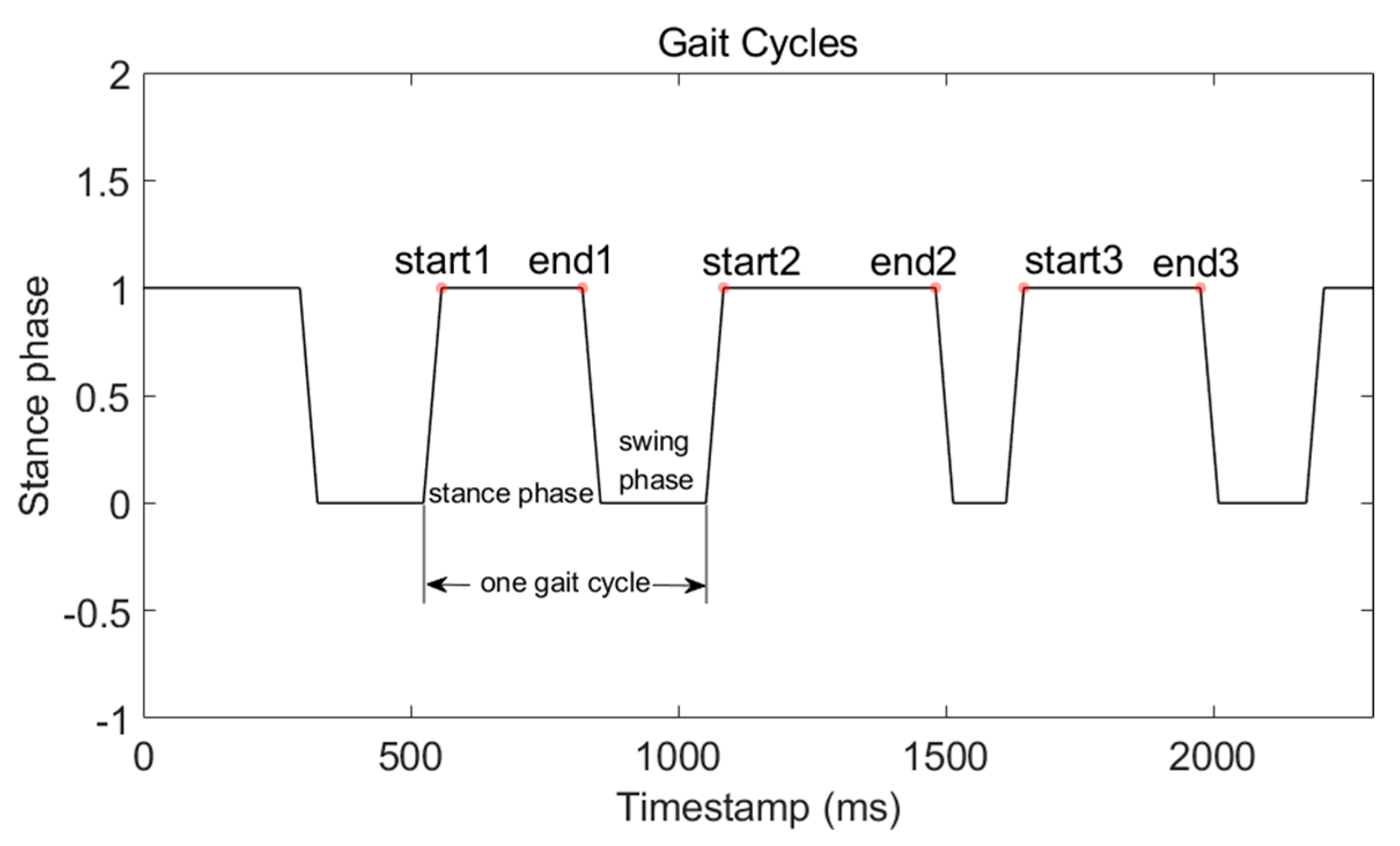
12]. In some other pedestrian inertial navigation systems, especially for fire-emergency applications, microelectromechanical system inertial-measurement units (MEMS-IMU) are mounted on the foot. With the triaxial accelerometer and gyroscope readings, a zero-velocity update (ZUPT) algorithm is developed to measure velocity errors in the stance phase of a gait cycle [
13,
14]. ZUPT estimates pseudo measurements into the extended Kalman filter (EKF) navigation-error corrector, which allows the EKF to correct velocity errors during each gait cycle, breaking the cubic-in-time error growth and replacing it with an error accumulation that is linear with the number of steps [
15,
16,
17]. This kind of foot-mounted inertial navigation system is called IEZ-INS and IEZ is short for the first letters of INS, EKF, and ZUPT. Foot-mounted MEMS-IMU can be used to get more accurate stride-length estimation [
18,
19,
20]. There is no clear boundary between PDR-INS and IEZ-INS. The principle of method choice depends on the accuracy of MEMS-IMU and the specific application.
Unlike infrastructure-free IPSs, infrastructure-based ones need preinstalled transmitters such as WiFi [
9,
21,
22], Bluetooth [
23,
24], near-field communication [
25], RFID [
26], ultrawide band (UWB) [
27,
28], LED [
29,
30], or ultrasound [
31]. These methods can provide sufficient positioning accuracy for LBSs in different applications. Widely deployed private- or public-access points (APs) in large-scale buildings can provide free and dense signals for WiFi-based IPS. Furthermore, smartphones are embedded with WiFi chips that can easily obtain a received signal-strength index (RSSI). The methods used in WiFi-based IPS can be classified by time of arrival (TOA) [
32], time difference of arrival (TDOA) [
33], angle of arrival (AOA) [
34], and RSSI fingerprinting [
35], CSI-fingerprinting [
36], and round-trip time (RTT) [
37]. Each of these methods has shortcomings and limitations. TOA, TDOA, and AOA are easily influenced by indoor environments. Channel state information (CSI) fingerprinting needs an Intel 5300 wireless local area networks (WLAN) card that is not available for smartphones. Similar with CSI fingerprinting, the AP of the RTT method must support IEEE 802.11 mc, which is brand-new and not in the commercial market yet. Therefore, considering the complex multipath effect and the available hardware, RSSI fingerprinting is widely researched.
The WiFi-fingerprinting method consists of two phases, the offline site-survey phase and the online positioning phase [
38]. In the offline phase, the WiFi-RSSI of selected APs is collected from each reference point (RP), and a radio map is built up. In the online phase, the collected WiFi-RSSI samples are compared with the radio map using matching algorithms such as k-nearest neighbor (KNN) to get the position estimation [
39]. One of the most important reasons that limit the large-scale implementation of WiFi-based IPS is that site surveys are very time-consuming and labor-intensive [
40]. For example, if we wanted to deploy the WiFi-IPS in a 10 m × 10 m room with a one-meter interval of each RP, and the WiFi-RSSI sampling time was 2 min of each RP, it would take 200 min to build the WiFi-RSSI radio map of this room in total. Time consumption would rise rapidly with the area of the place deploying WiFi-IPS [
41].
To make WiFi-based IPS more practical, many researchers have focused on how to build the radio map in an energy-efficient way. The most common format of a WiFi-RSSI radio map is {RP coordinates, WiFi-RSSI vectors}. The offline WiFi-RSSI radio-training phase is very time-consuming because volunteers must stand still for a while to collect WiFi-RSSI from every RP [
42]. Therefore, methods aiming to reduce the manpower of building a WiFi-RSSI radio map either research the model of WiFi-RSSI or add extra devices and sensors to help estimate RP coordinates [
38,
40]. According to Reference [
43], methods that try to replace the construction of the radio map by using indoor radio-propagation models cannot capture all the details of the indoor structure and dynamics. These methods either achieve a very unsatisfactory performance or rectify model inaccuracies through extensive calibration and exhaustive postprocessing to obtain a map that can achieve more acceptable localization accuracy. In Reference [
44], a WiFi-enabled laptop and an attached GPS device were used to scan the WiFi-RSSI in the metropolitan-scale area. RP coordinates were provided by the GPS device recording the latitude–longitude coordinates of the war driver when the WiFi-RSSI scan was performed. However, this method is limited indoors, and large GPS positioning is not accurate enough for calculating RP coordinates. In Reference [
45], nanoscale unmanned aerial vehicles (UAVs) were used to automate the WiFi-RSSI collection process. RP coordinates were calculated through a UWB-based localization subsystem. This method can build a 3D WiFi-RSSI radio map with low manpower. With the high accuracy of UWB-based IPS, the performance of an automatically built WiFi-RSSI radio map is similar with the manually built one. However, it needs extra equipment, like UAVs and UWB anchors that increase the cost.
With the rapid development of the electronic industry, a state-of-the-art smartphone is a good platform embedded with multiple sensors like accelerometers, gyroscopes, and magnetometers to measure pedestrian movement, and WiFi chips to scan WiFi-RSSI. In Reference [
46], a method called crowdsourcing and multisource fusion-based fingerprint sensing (CMFS) was presented. Based on the floor plan, RSSI is collected uniformly by WiFi scanner at fixed time intervals. Simultaneously, stride length, step number, and heading direction of volunteers were estimated using PDR-INS method. The drawback of this method is the drawback of PDR-INS. Stride-length parameters like pedestrian height and step frequency must be tuned according to different volunteers. In addition, heading direction is calculated using magnetic-field strength that may have non-negligible bias indoors. In Reference [
47], a WiFi-RSSI radio map was built using an inertial navigation solution from a Trusted Portable Navigator (T-PN) with handheld smartphones. The method of calculating RP coordinates was T-PN, which improves the accuracy of RP coordinates with absolute measurements like A-GPS, magnetometer, or barometer as filter updates. However, the accuracy of T-PN decreases indoors. In Reference [
48], a zero-effort crowdsourcing method (Zee) was developed. Zee used inertial sensors of smartphones and detailed map information to count steps and estimate heading offset. An augmented particle filter was utilized to estimate stride length with map information. Then, WiFi-RSSI was recorded to the radio map with RP coordinates through the same timestamps. However, Zee needs detailed map information that is not always available.
In this paper, we proposed a method called LSS-RM, short for Lightweight Site-Survey Radio Map, to construct the WiFi-RSSI radio map. This method, which can scan WiFi-RSSI, can significantly reduce the time consumption of offline WiFi-RSSI radio-map construction. Similar with other WiFi fingerprinting-based systems, our method also consists of an offline site-survey phase and online-positioning phase. The offline phase of LSS-RM is divided into the data collection and preprocessing process, and the post calibration process. The site survey is a client–server model in which the WiFi-based IPS service provider hires some volunteers to participate in site-survey work. To attract more volunteers to a boring site survey, the incentive mechanisms developed in Reference [
49] can be applied.
The remainder of this paper is organized as follows:
Section 2 is the overview of our WiFi-RSSI LSS-RM. In
Section 3, the data collection and preprocessing processes are described. In
Section 4, the post calibration process is described. In
Section 5, experiments were performed, and the performance of the WiFi-RSSI radio map built with our method was evaluated. Finally,
Section 6 concludes this work and offers future research suggestions.
2. Overview of LSS-RM
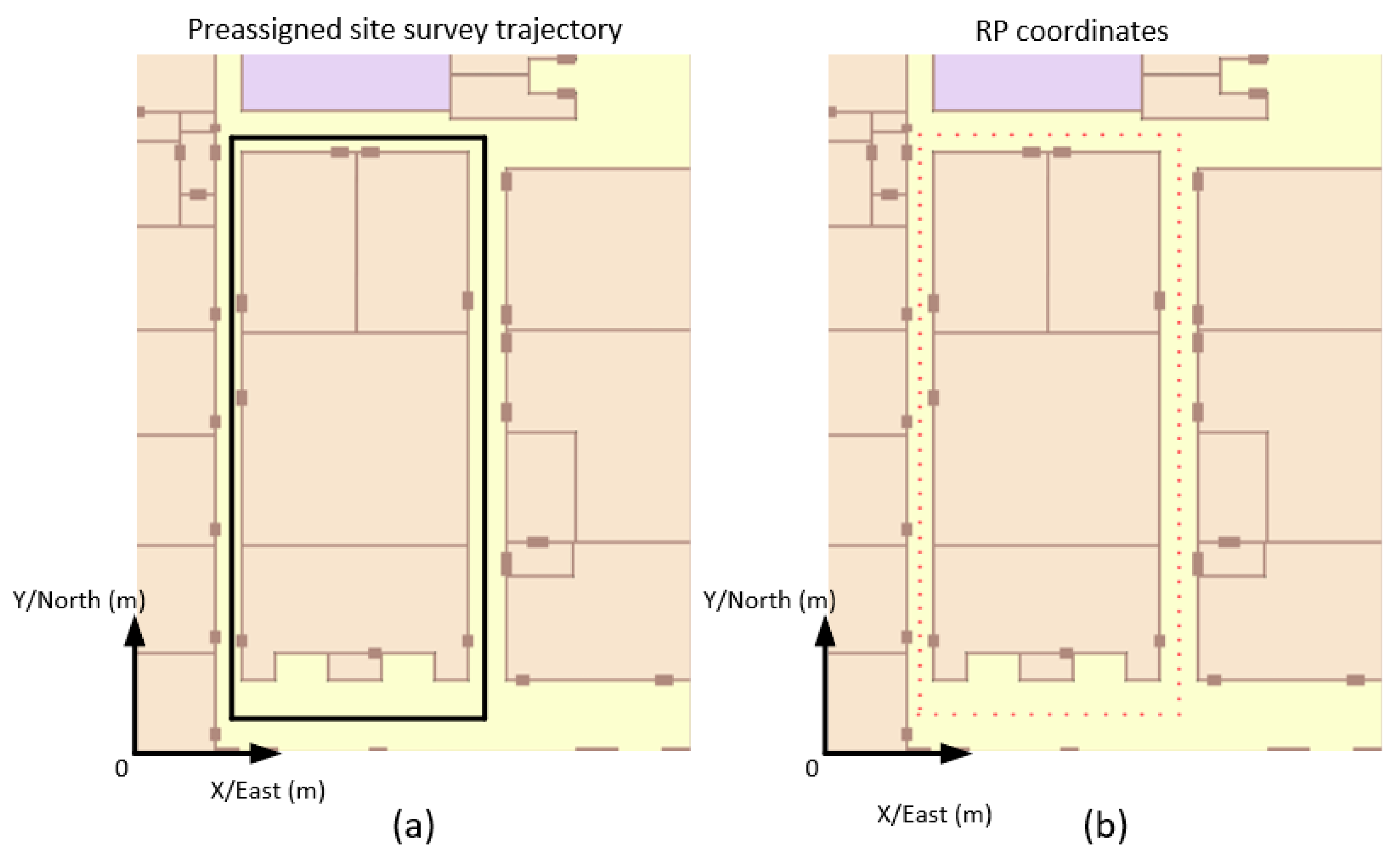
The WiFi-RSSI radio map consists of RP coordinates and a WiFi-RSSI vector. In the traditional manual site survey, a floor plan with detailed RP coordinates is provided to trained persons who are familiar with the site-survey process, usually from the service-provider group. Then, site-survey participants stand on each RP to scan WiFi-RSSI using smartphones. The most time-consuming part of the site survey is the manual WiFi-RSSI scan process. In this paper, site-survey participants did not need to stand still at each RP, instead walking along the preassigned site-survey trajectory, and the WiFi-RSSI radio map was automatically constructed.
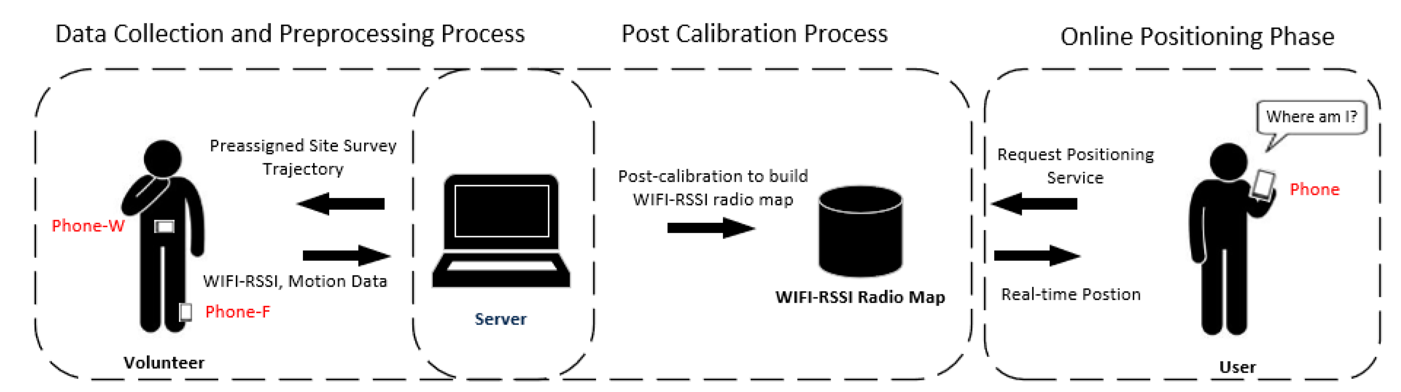
The structure of LSS-RM is shown in
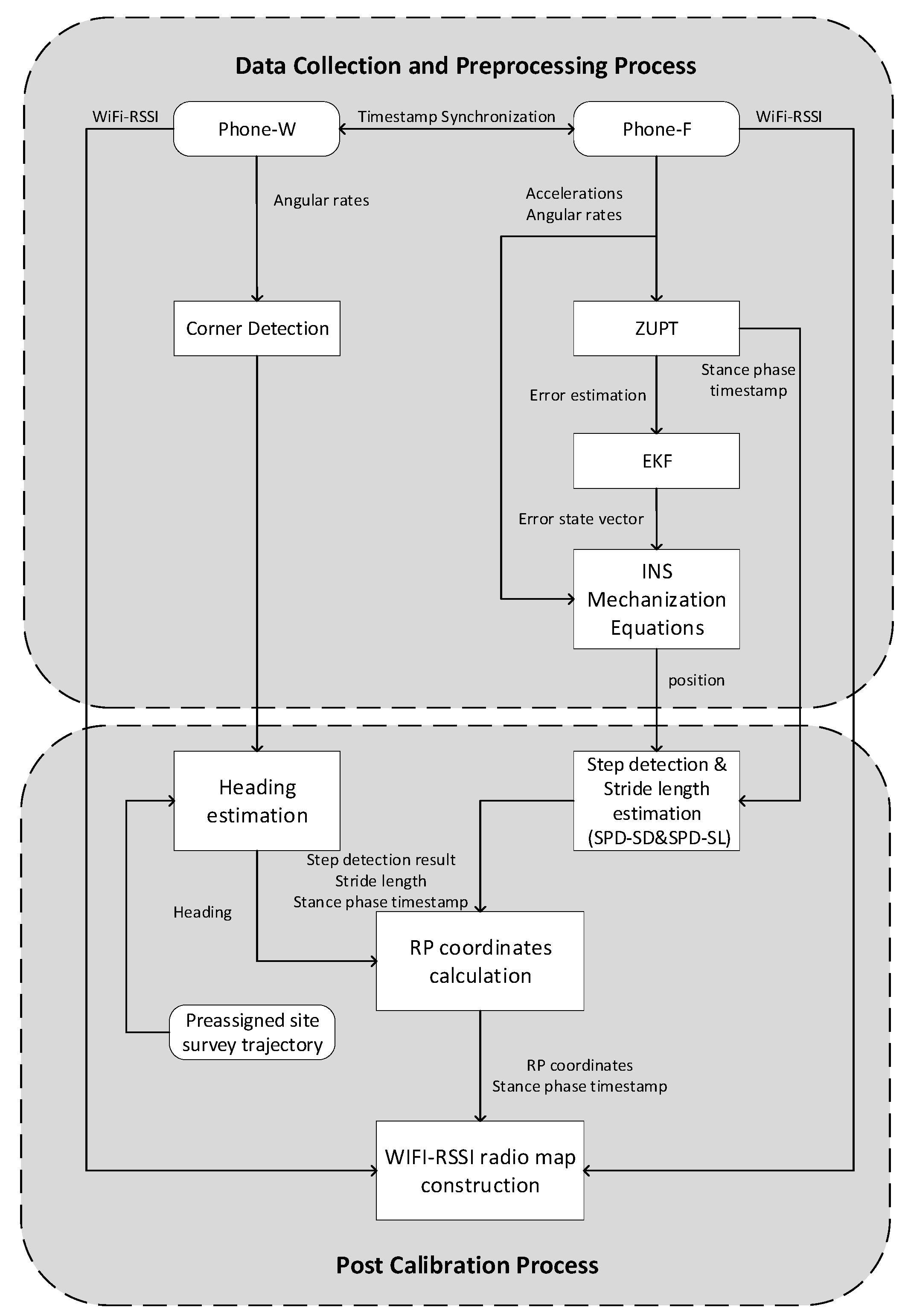
Figure 1. The preassigned site-survey trajectory was told to volunteers, and then two smartphones were mounted on the waist (Phone-W) and the foot (Phone-F), respectively. The movement of the volunteer was recorded using a smartphone-embedded MEMS accelerometer, gyroscope, and magnetometer. WiFi-RSSI was also scanned by Phone-W and Phone-F at the same time. Volunteers did not need to take care of their walking frequency or step stride, but just took two smartphones to walk along the preassigned site-survey trajectory, and the WiFi-RSSI radio map was built up automatically. Phone-F could detect zero velocity and the IEZ-PDR algorithm was implemented to calculate the position of volunteers. The angular rate energy-detection algorithm using Phone-W motion data was applied to detect corners of the preassigned site-survey trajectory. Positioning results, stance phase estimation results, and WiFi-RSSI were transferred to the server in real time through the public 4G long term evolution (LTE) network for the post calibration process. In this process, a stance-phase detection-based algorithm is used to count steps and to estimate stride length. With accurate corner detection and preassigned site-survey trajectory information, we could calculate the accurate heading of the volunteers. Finally, with accurate step numbers, stride length, and heading, precise RP coordinates were calculated. The bridge between RP coordinates and WiFi-RSSI in LSS-RM is the start and end timestamp of each stance phase. After the two processes of the offline site-survey phase, a WiFi-RSSI radio map was built up. In the online-positioning phase, when a user sent a demand for the position service, real-time WiFi-RSSI was collected from the user’s smartphone, and a matching algorithm like k-nearest neighbor (KNN) was used to obtain the user’s position. Finally, the real-time localization results were sent back to the user’s smartphone.
The flowchart of LSS-RM is shown in
Figure 2. It has the following nine steps. Steps (1) to (5) happen in the data collection and preprocessing process, and Steps (6) to (9) happen in the post calibration process.
- (1)
The volunteer is told they should walk along the preassigned site-survey. The server analyzes whether the volunteer walks in the right way.
- (2)
Two smartphones are mounted on the foot (Phone-F) and waist (Phone-W) of the volunteer, respectively. Motion data of the volunteer, such as accelerometer readings, gyroscope readings, and magnetometer readings are recorded in a format {Timestamp, Triaxial Accelerations, Triaxial Angular Rates, Triaxial Magnetic Field Strength}. Simultaneously, WiFi-RSSI data are recorded by both smartphones in a format {Timestamp, WiFi-RSSI Vector}. The timestamp can be used as a medium to connect the two different kinds of data.
- (3)
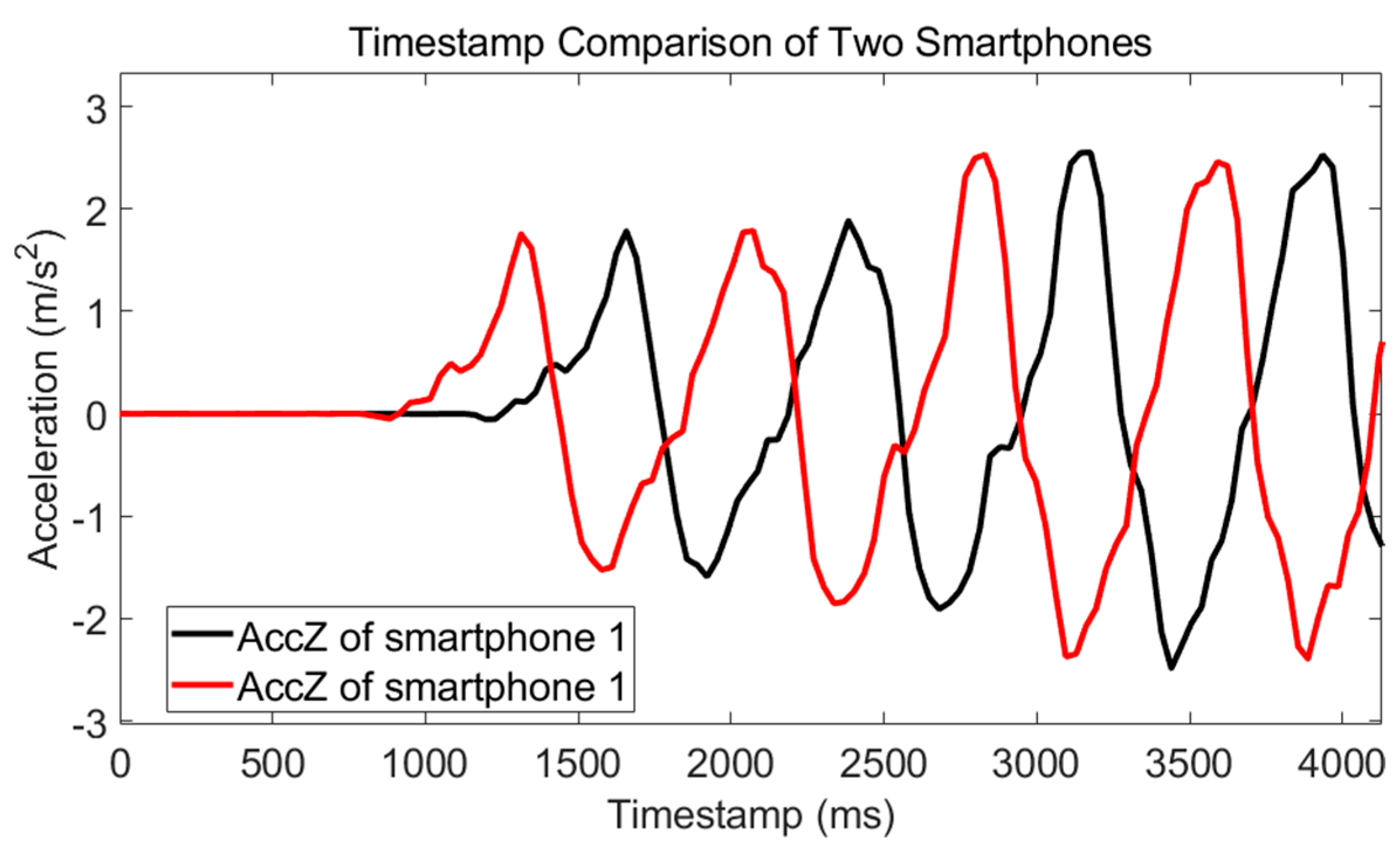
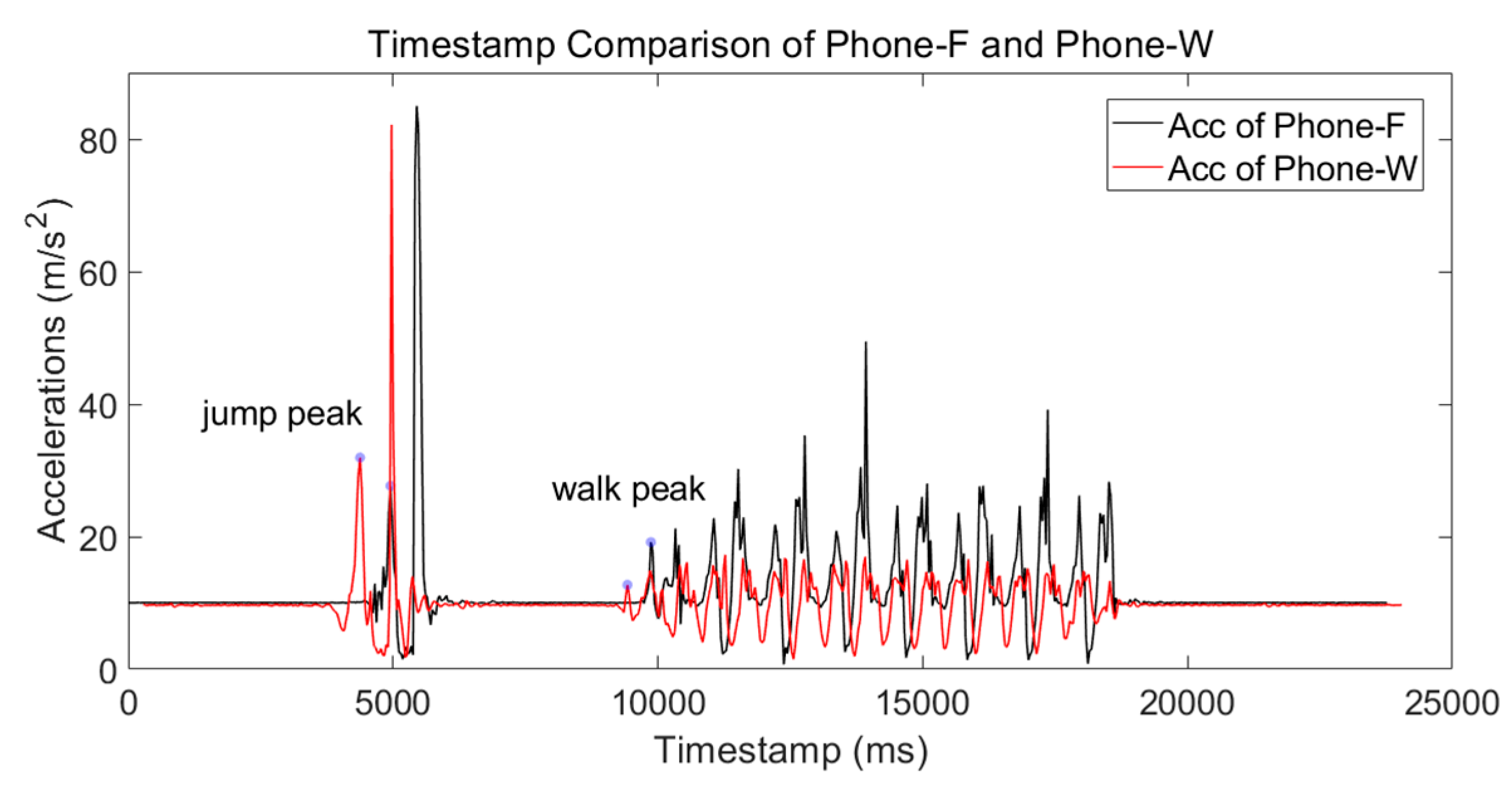
The timestamp difference of Phone-F and Phone-W is measured. Then, a timestamp-synchronization process is taken to align data from the two smartphones.
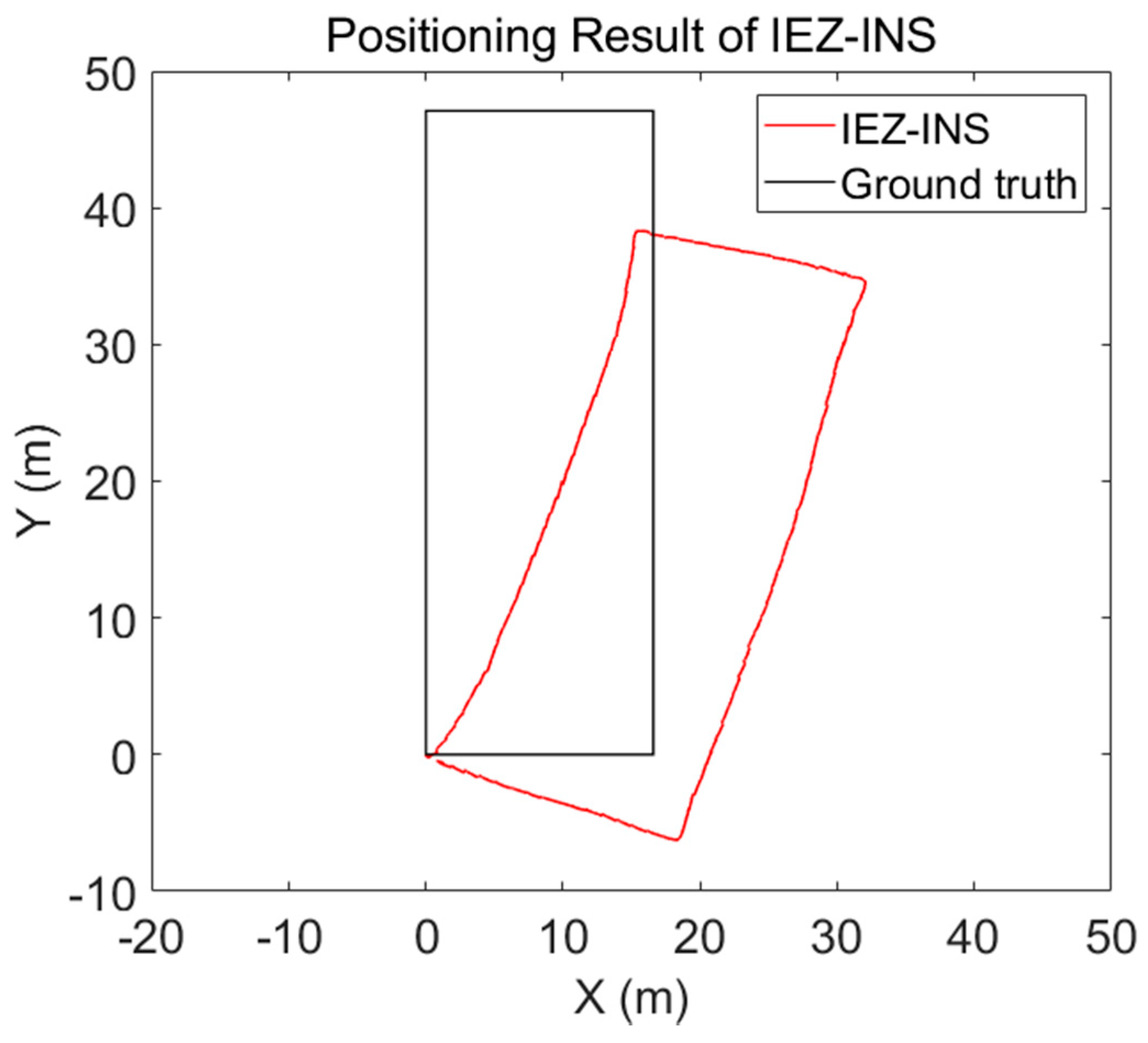
- (4)
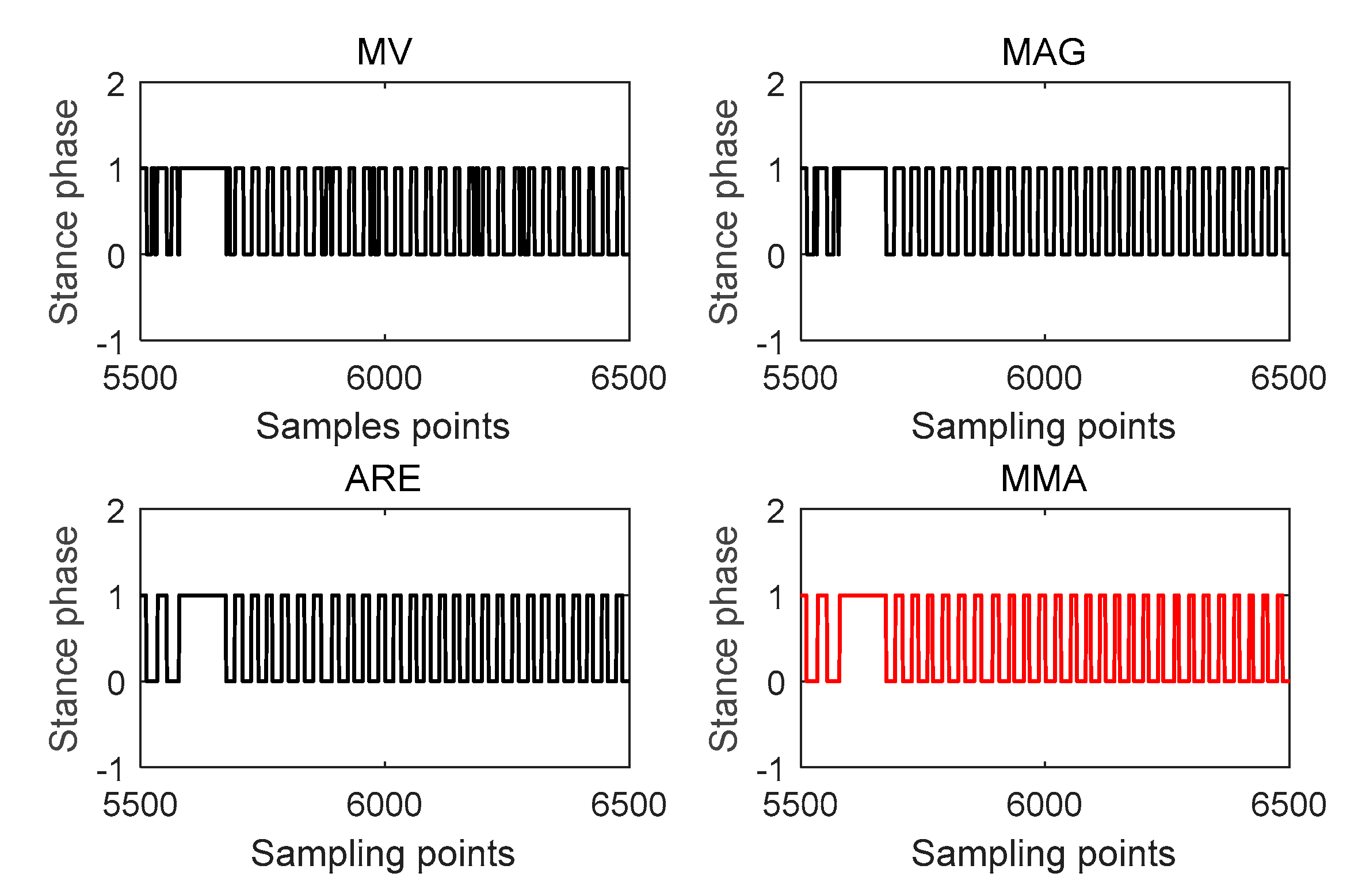
The position of the volunteer is calculated using the IEZ-INS method based on the accelerometer readings, gyroscope readings, and magnetometer readings of Phone-F. In this step, the stance-phase result of ZUPT is very important and will be used in the post calibration process.
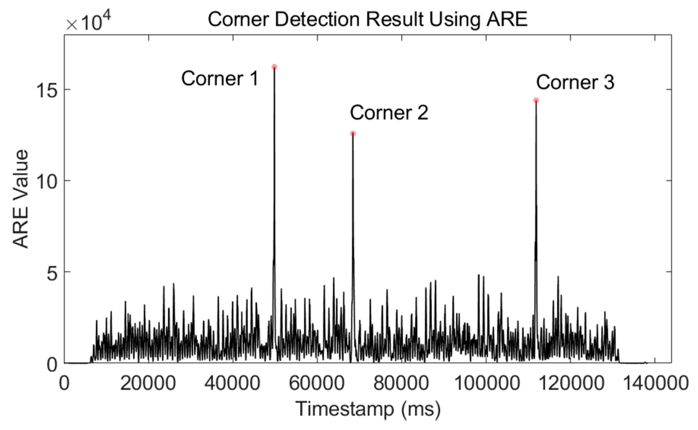
- (5)
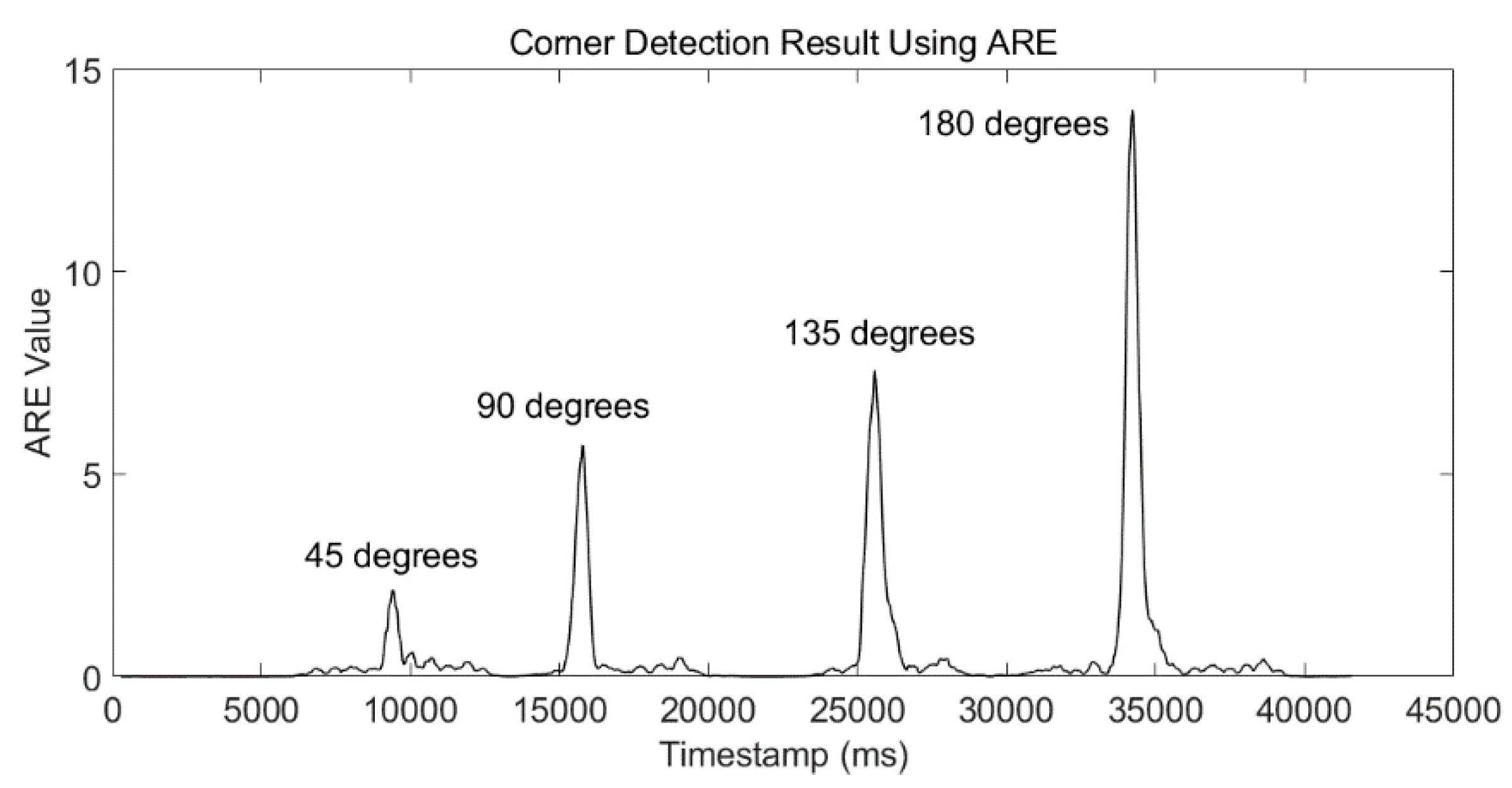
The angular-rate energy detector (ARE) is used to detect the corner based on gyroscope readings of Phone-W. The corner-detection result can be used to calculate the heading with the preassigned site-survey trajectory in the post calibration process.
- (6)
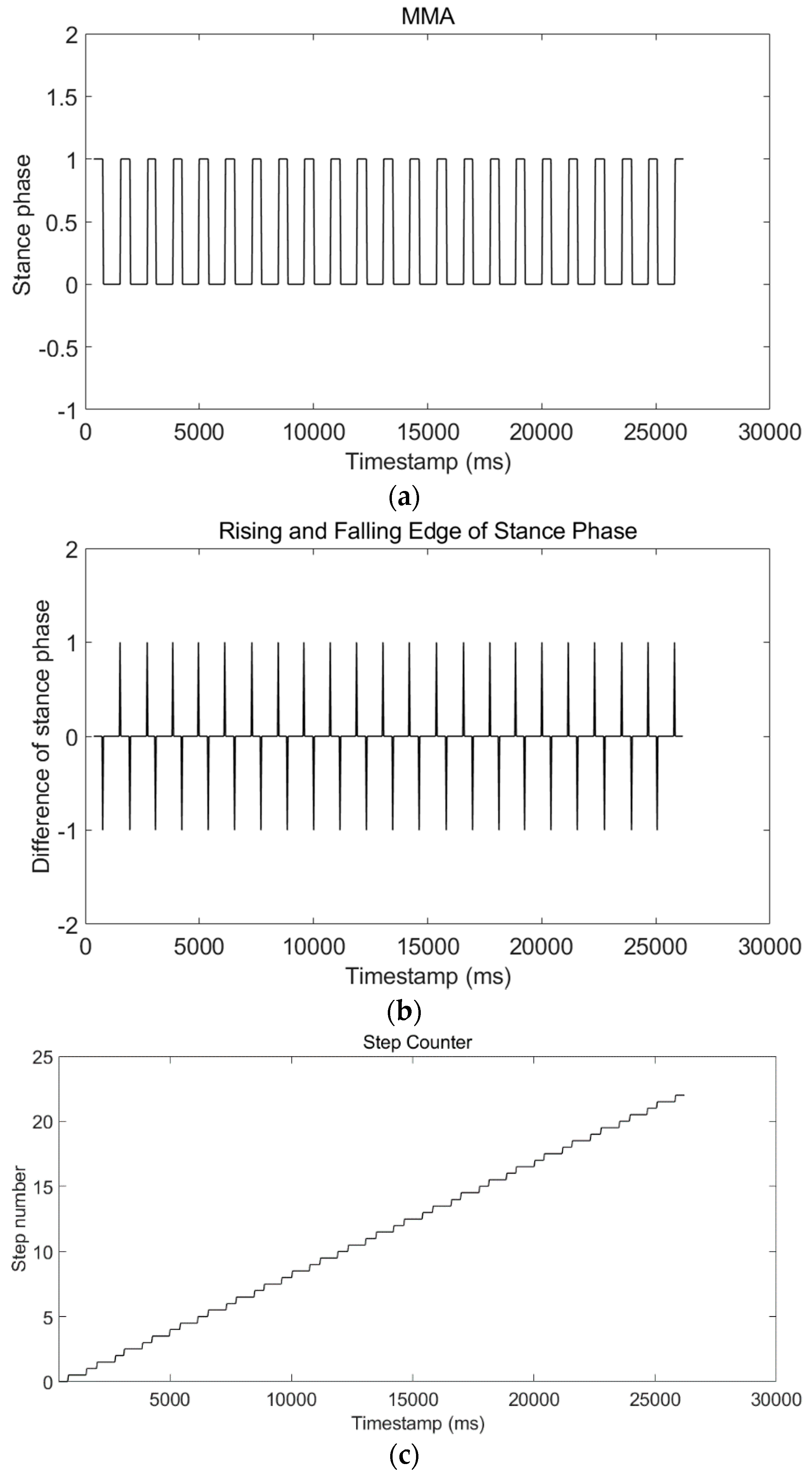
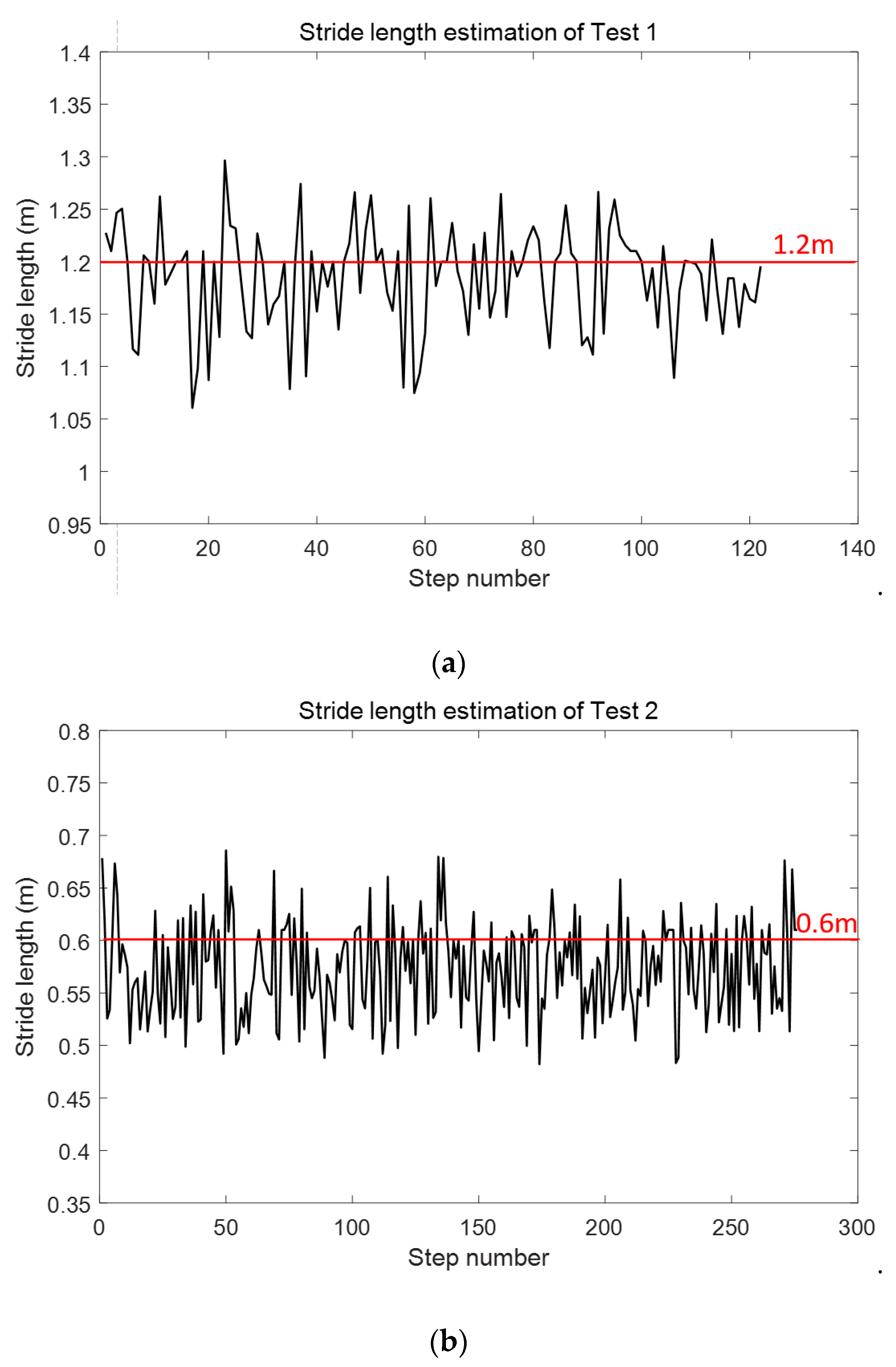
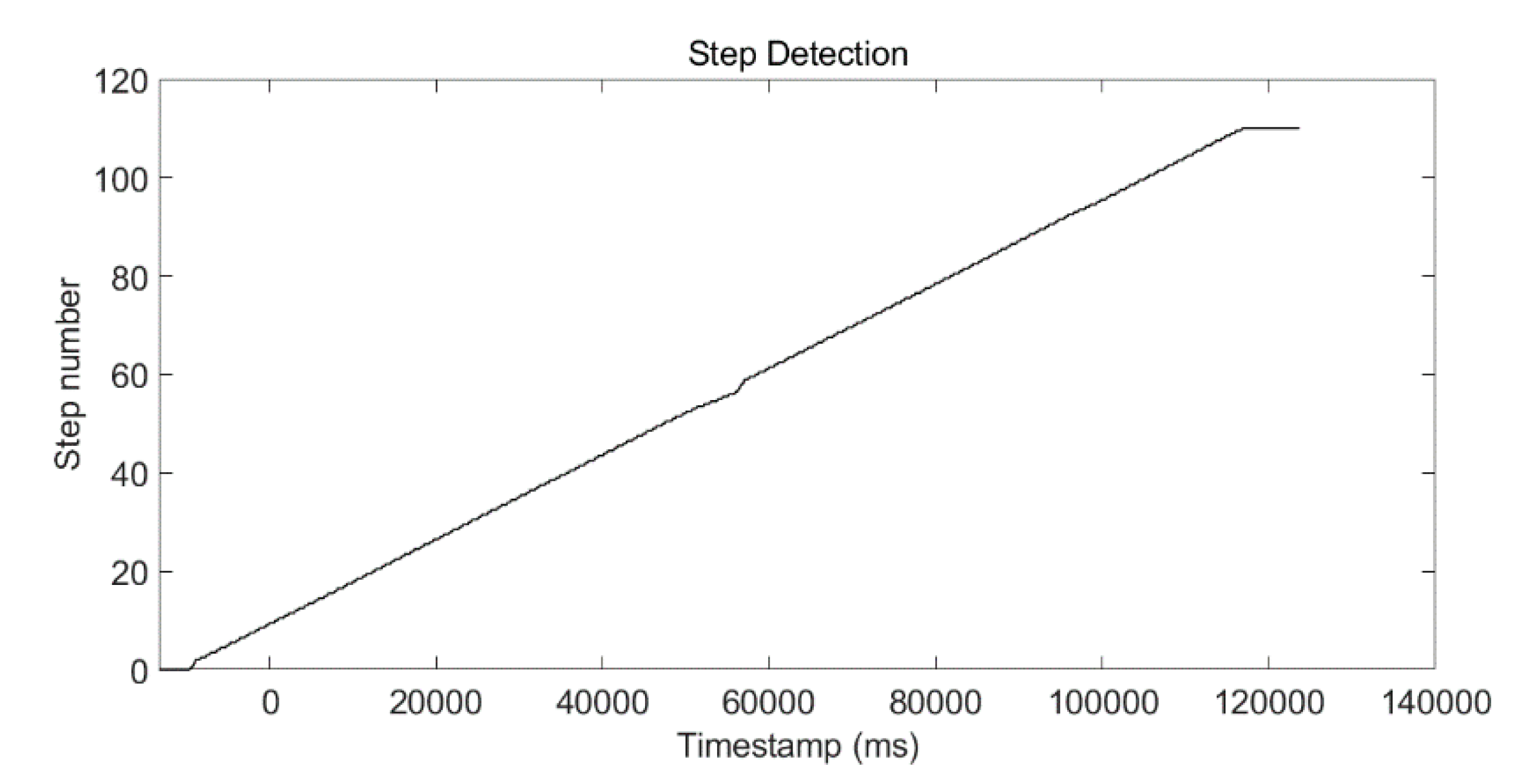
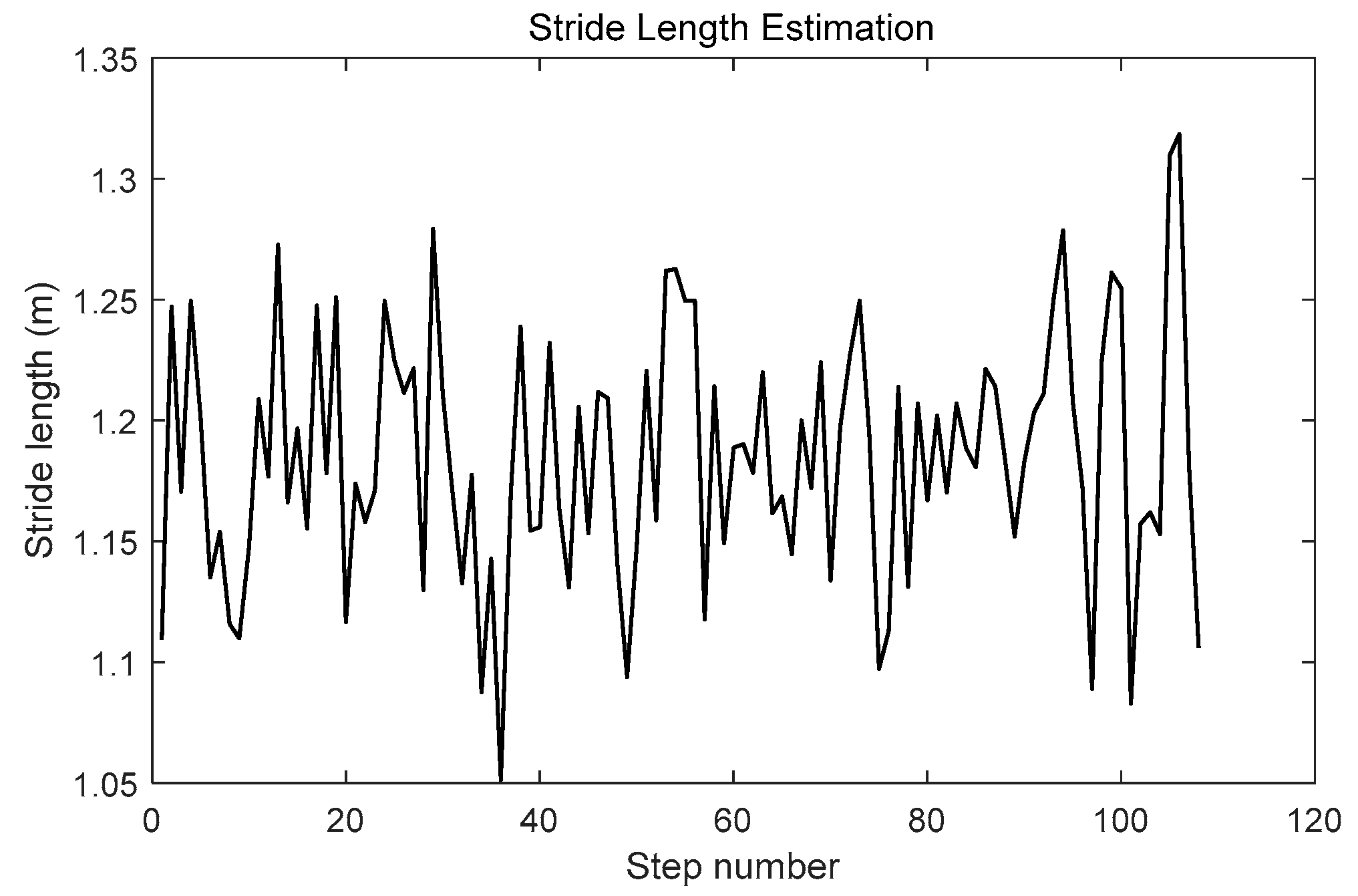
Step number and stride length are estimated based on stance-phase detection from Phone-F.
- (7)
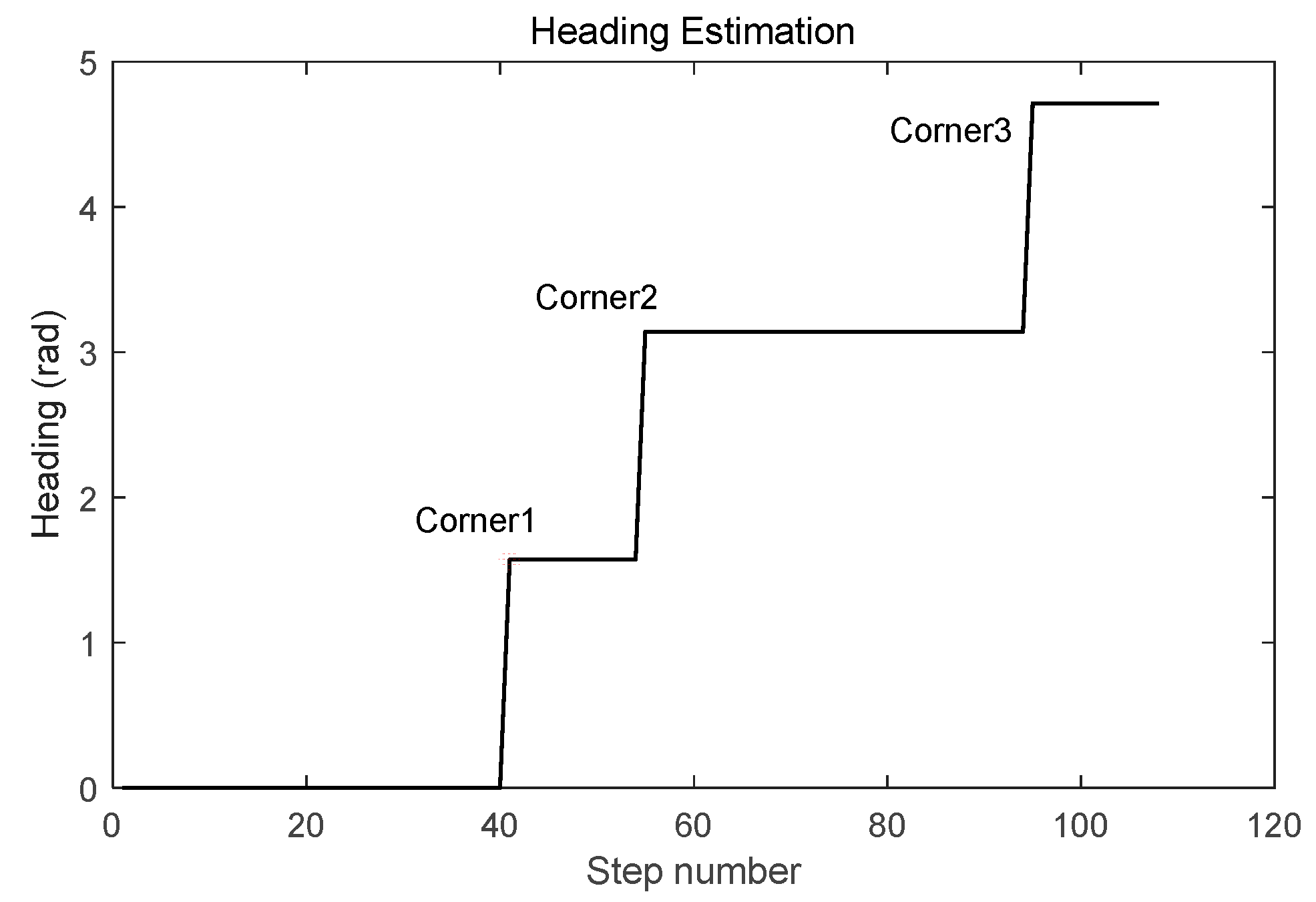
Heading of the volunteer is calculated based on preassigned site-survey estimation and corner-detection result from Phone-W.
- (8)
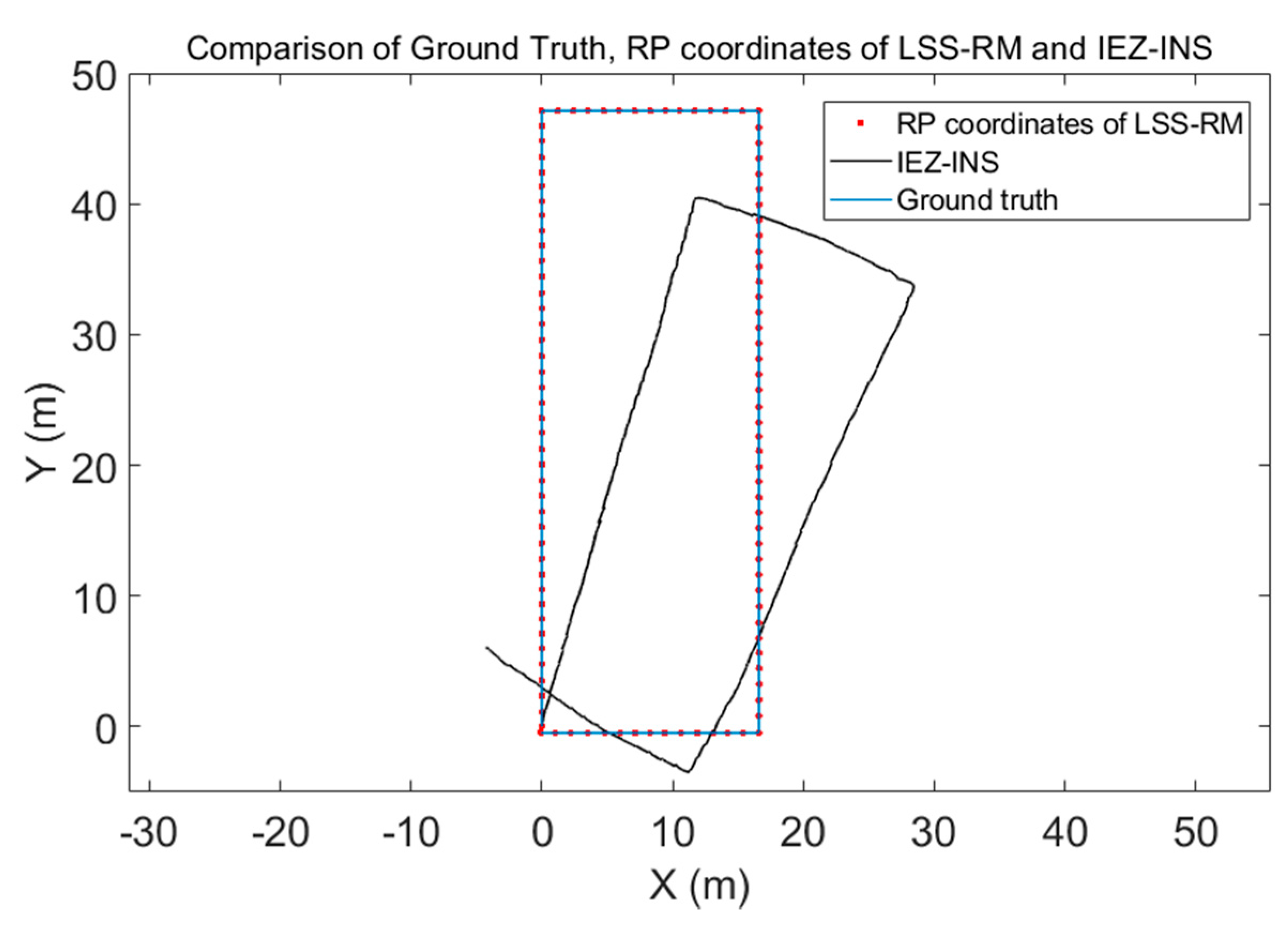
RP coordinates are calculated using the post calibrated step number, stride length, and heading based on the PDR-INS method.
- (9)
A radio map is built up with RP coordinates and WiFi-RSSI vectors in a traditional radio map format {RP coordinates, WiFi-RSSI vectors}. The bridge between RP coordinates and WiFi-RSSI vectors in the LSS-RM method is the start and end timestamp of each stance phase.
The offline site-survey phase of WiFi-fingerprinting-based IPS is a trade-off between manpower and radio-map accuracy. Like other methods, our LSS-RM method also aims to find a balance in the trade-off. Comparing with other methods, the advantage of LSS-RM is that no extra devices except for smartphones are needed, and volunteers don't need to take care of their step frequency or stride length to reduce the time-consumption of the offline site survey.
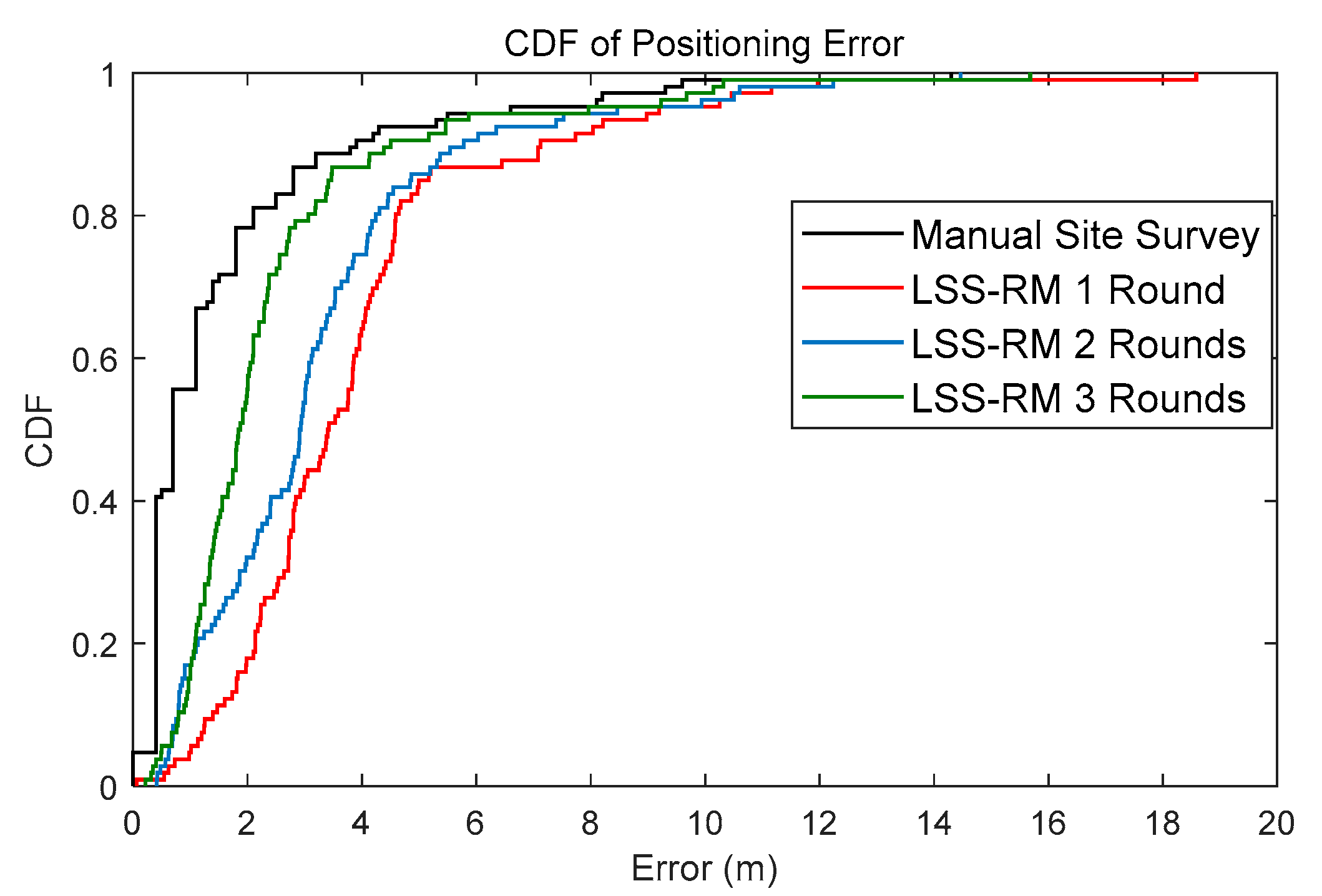
However, LSS-RM still has some drawbacks. Firstly, the system is more complex. Two smartphones are needed in LSS-RM. Despite the advantage of better RP coordinates and denser WiFi-RSSI, the system is more complicated than the traditional one. Secondly, the preassigned site-survey trajectory is needed, and the volunteer must walk along it. Thirdly, considering that the scanning time of LSS-RM on each RP is shorter than in manual site surveys, initial positioning accuracy will be lower. However, with more volunteers joining in the offline phase, positioning accuracy increases. Fourthly, the reliability of LSS-RM depends on the accuracy of RP-coordinate estimation, which can be influenced by many factors like the drift of the MEMS-IMU, the timestamp-alignment accuracy of the two smartphones, and the accuracy of the preassigned site-survey trajectory. With the post calibration process, reliability can be improved. In conclusion, there is still a long way to realize the complete site-survey free WiFi-RSSI radio-map construction method.


