Steering Algorithm for a Flexible Microrobot to Enhance Guidewire Control in a Coronary Angioplasty Application

 ,
,
Abstract
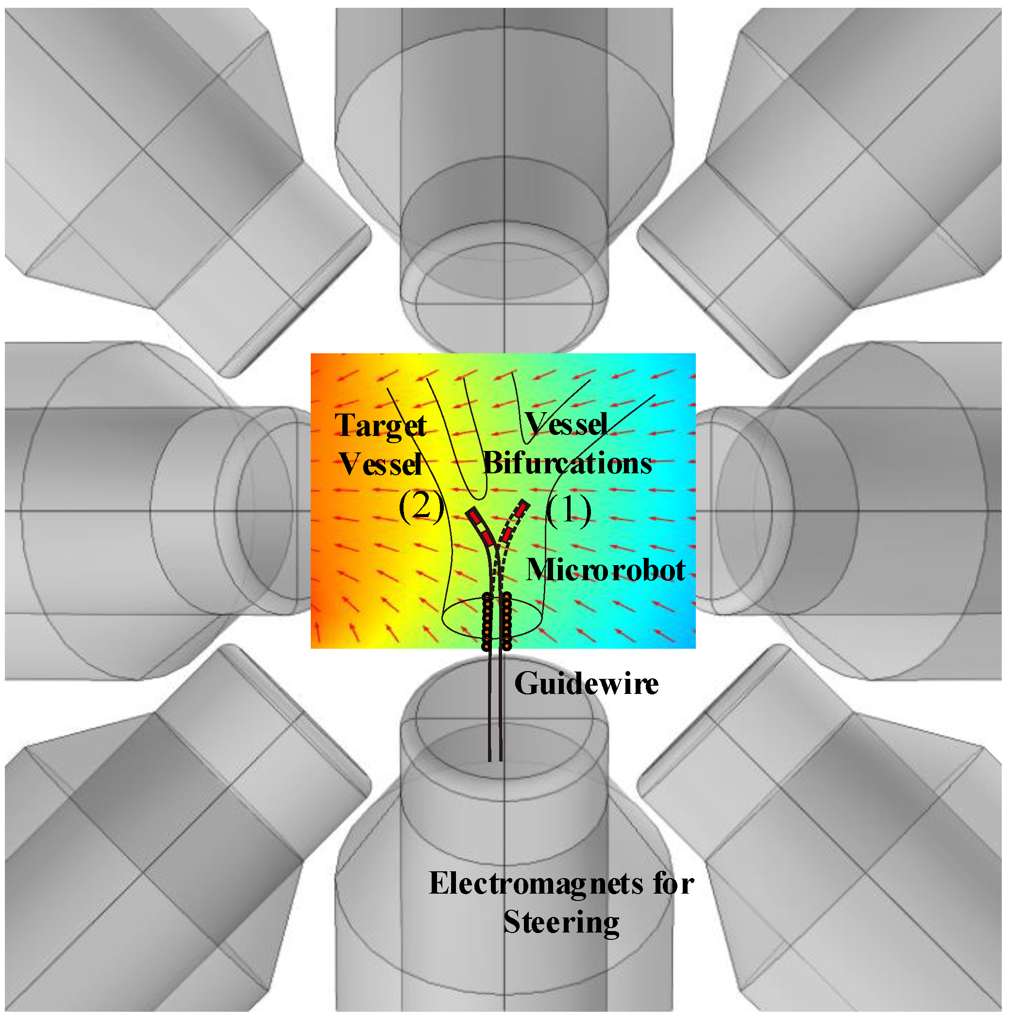
:1. Introduction
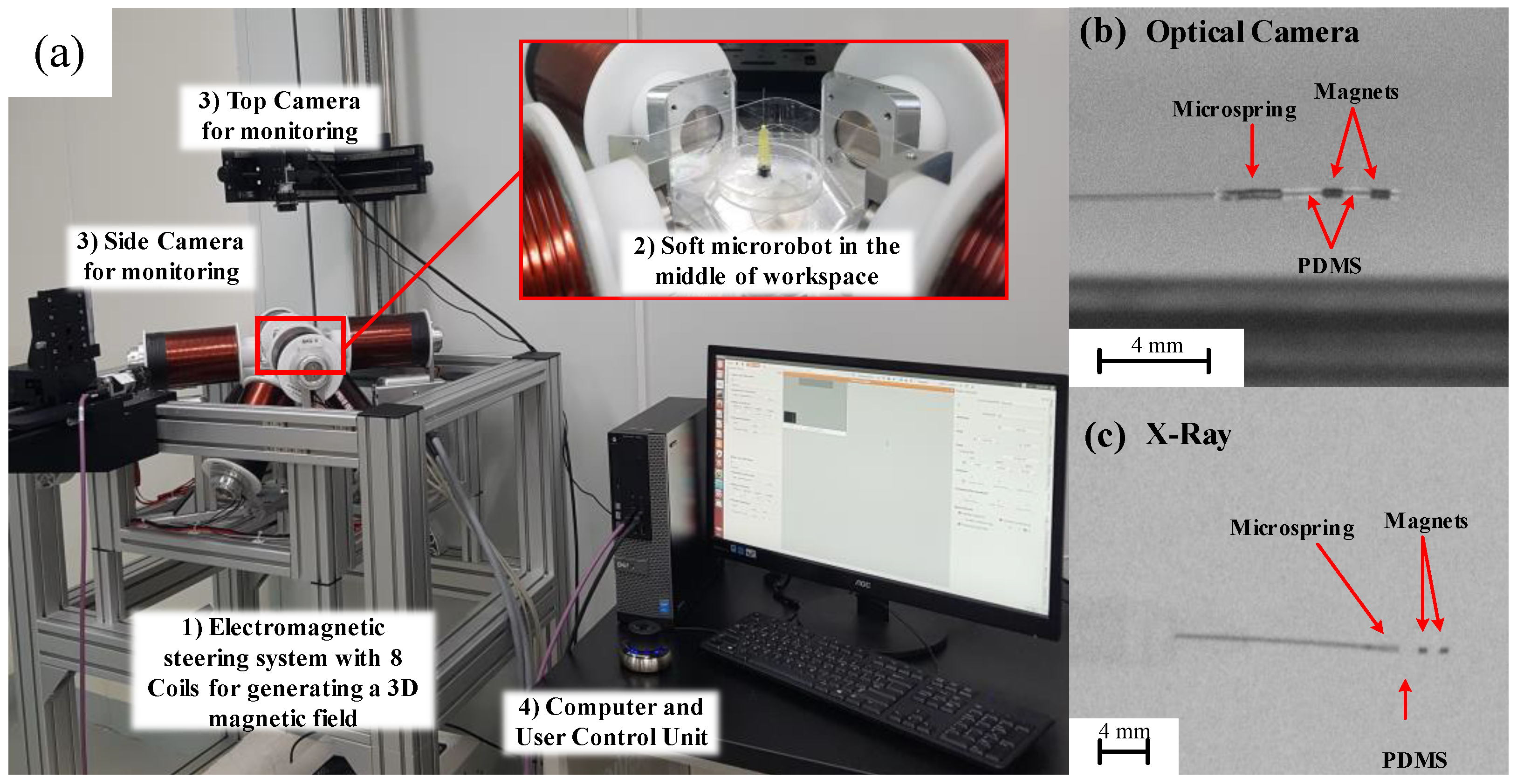
2. Flexible Microrobotic Platform
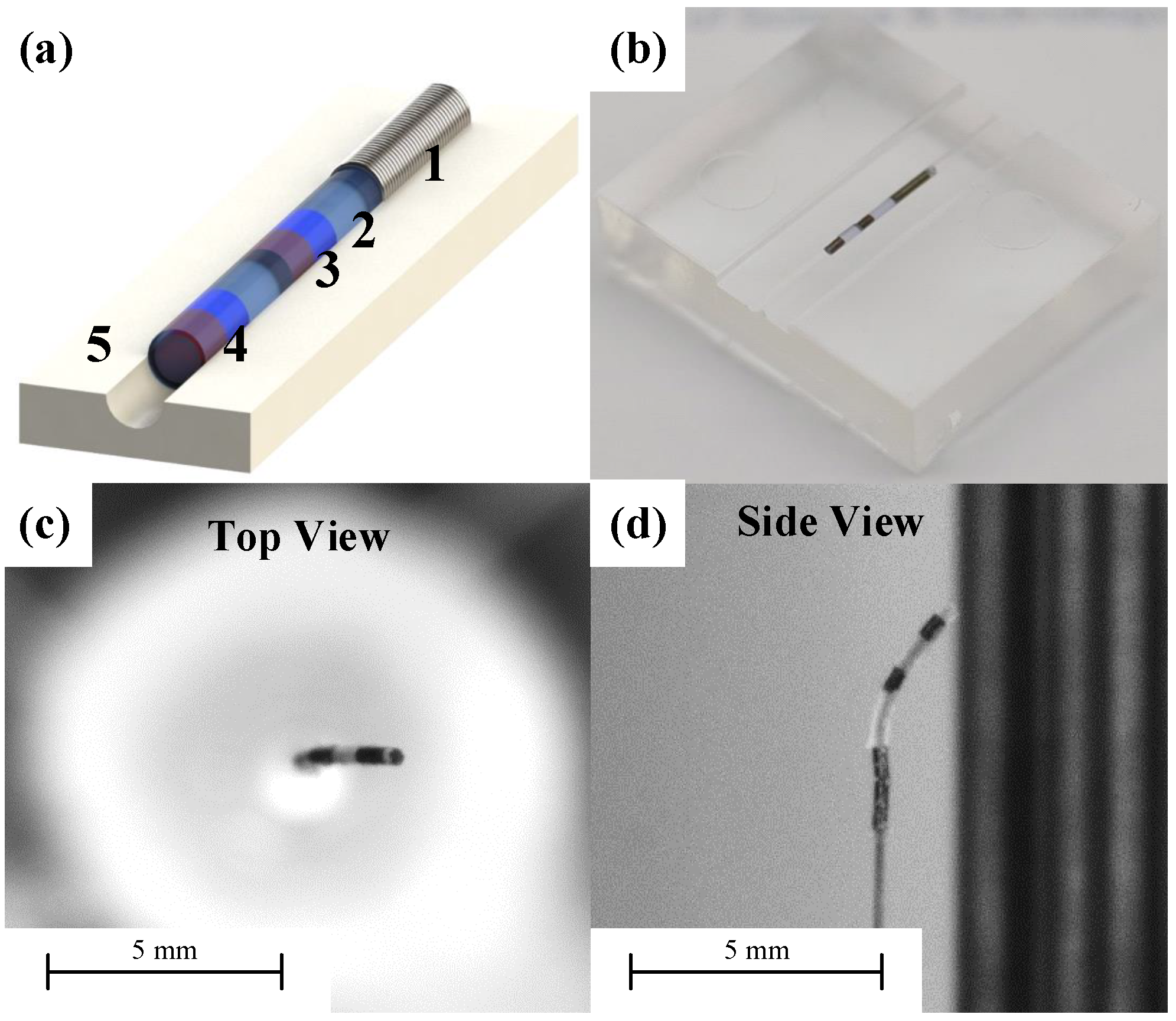
The Microrobot Fabrication
3. Modeling for Microrobot Steering
3.1. Electromagnetic Force and Torque
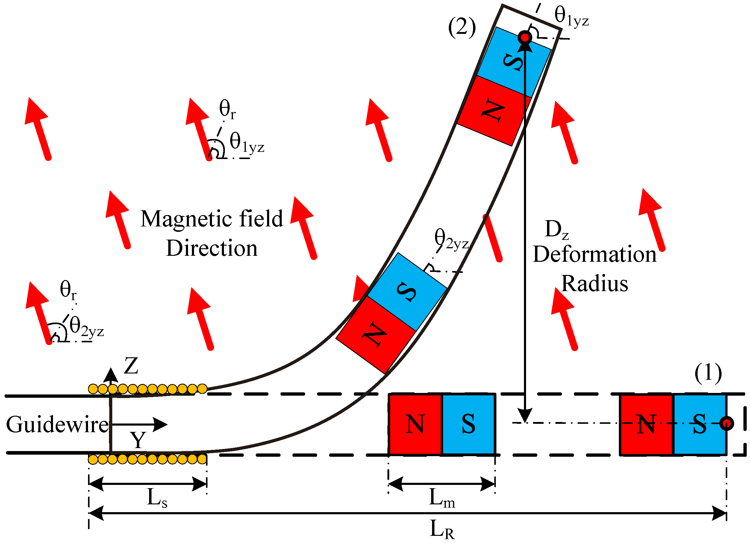
3.2. The Microrobot Deformation
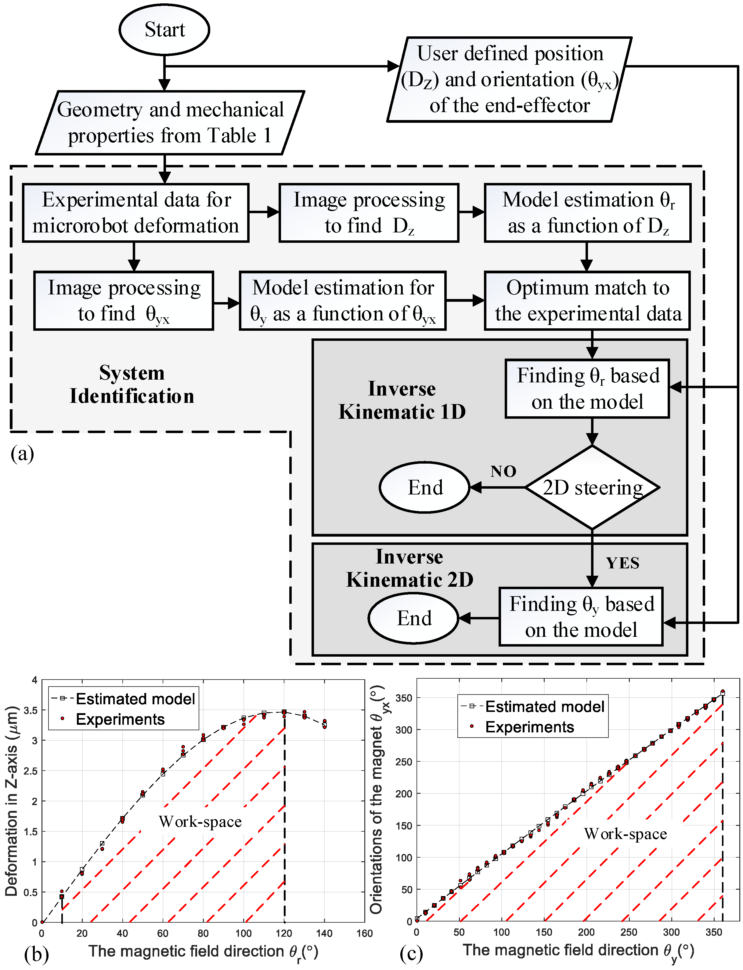
3.3. Modeling Algorithms
System Identification
4. Results and Discussion
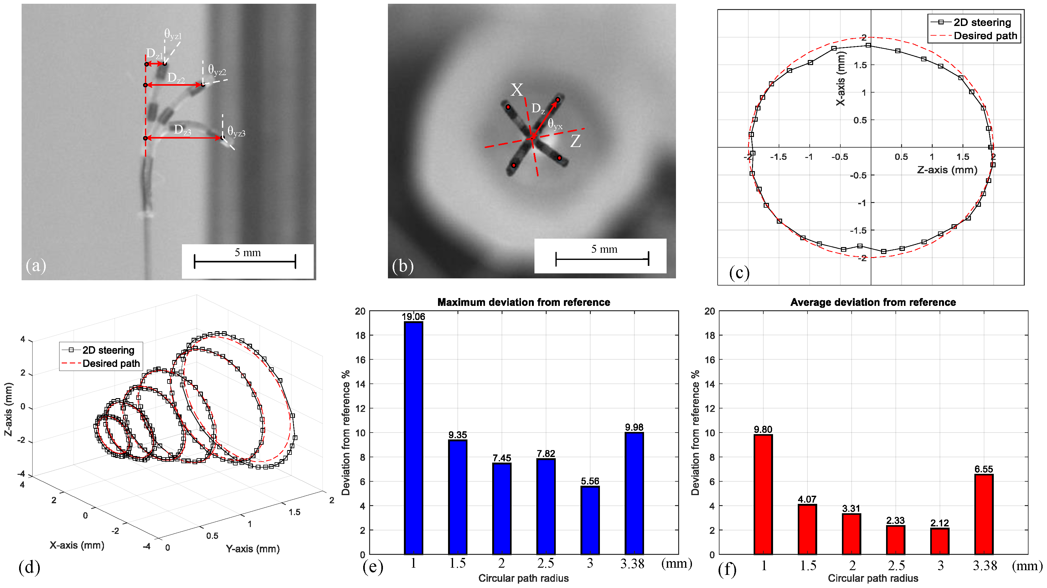
4.1. Two Dimensional Steering Experiment
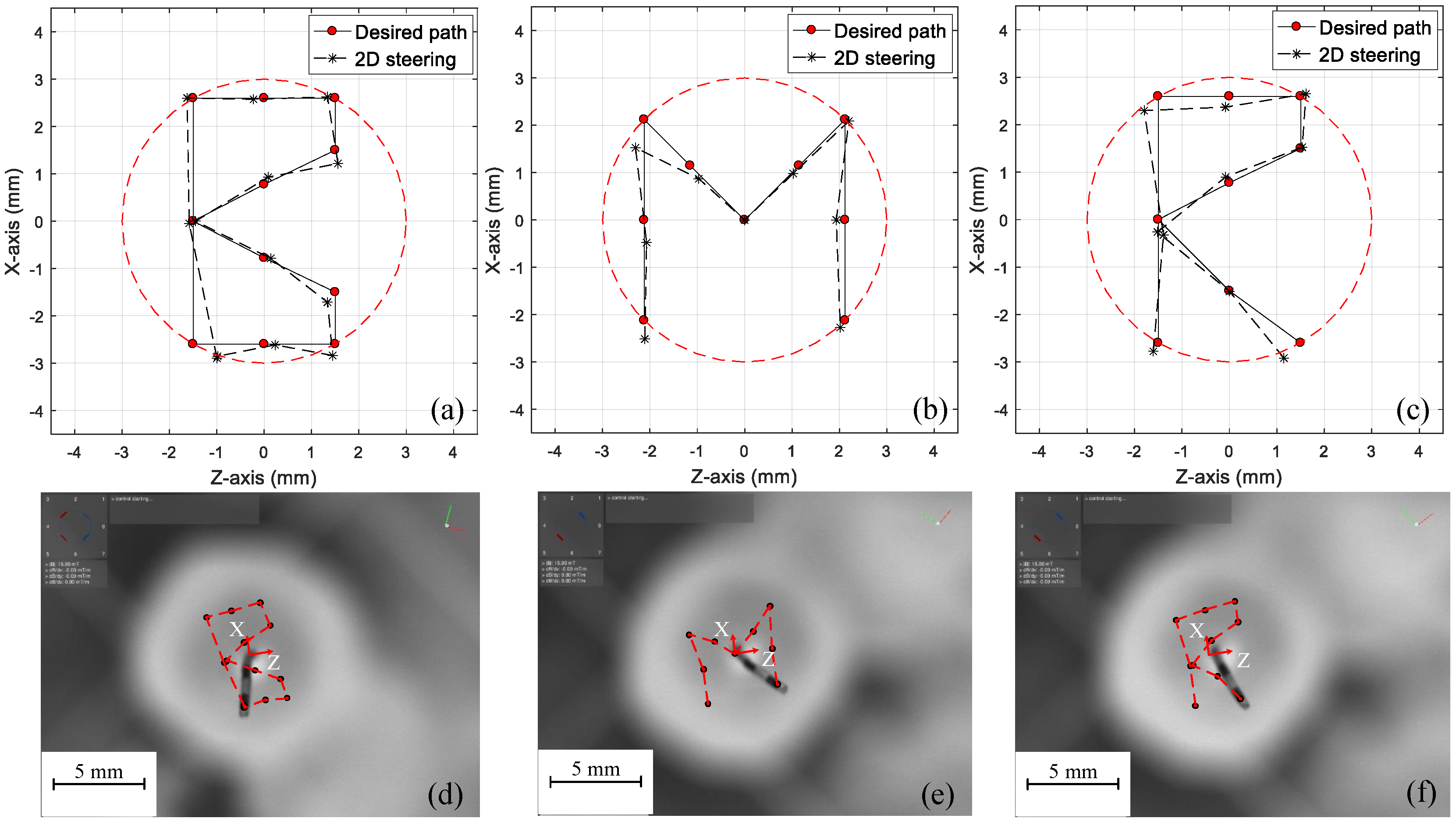
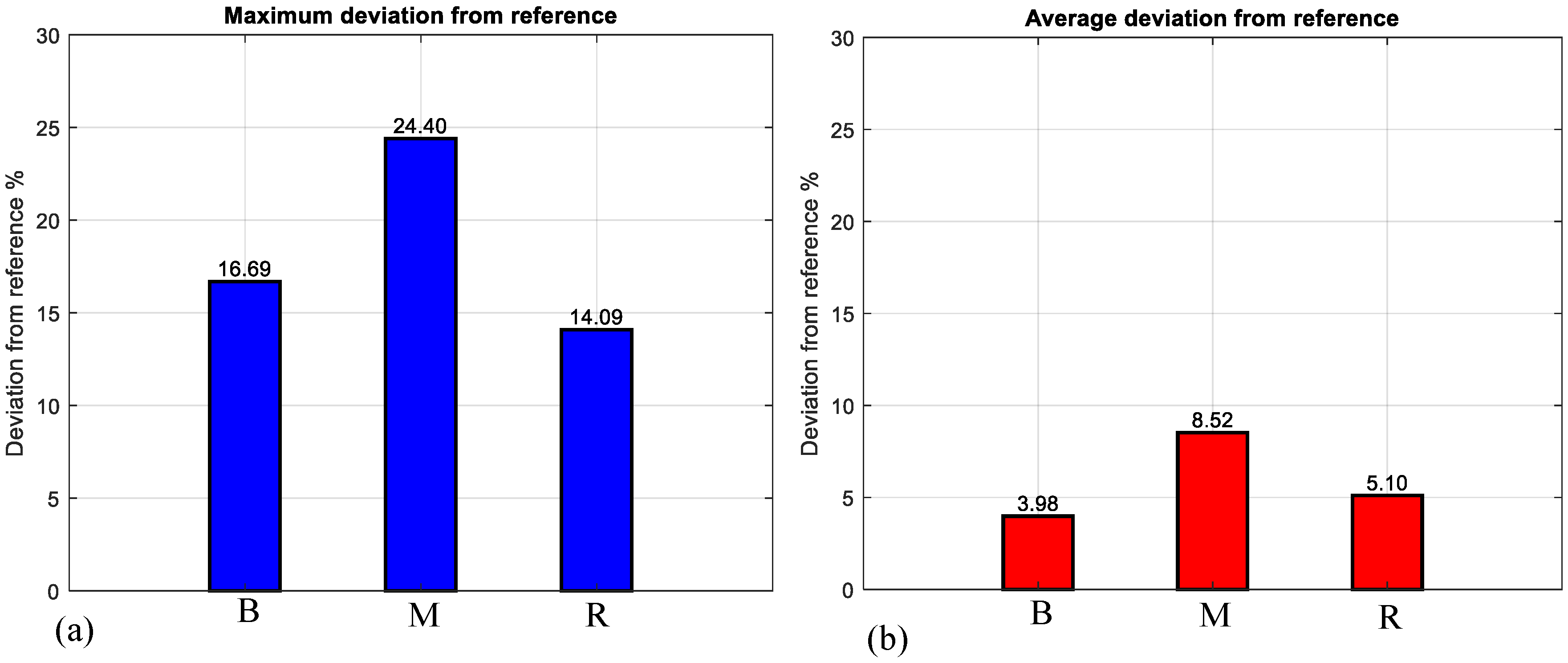
4.2. Microrobot Steering in an Arbitrary Path
4.3. The Guidewire-Steered Microrobot
5. Conclusions
Supplementary Materials
Author Contributions
Funding
Conflicts of Interest
References
- Lee, S.; Kim, S.; Kim, S.; Kim, J.Y.; Moon, C.; Nelson, B.J.; Choi, H. A Capsule-Type Microrobot with Pick-and-Drop Motion for Targeted Drug and Cell Delivery. Adv. Healthc. Mater. 2018, 7, 1700985. [Google Scholar] [CrossRef] [PubMed]
- Kim, S.; Qiu, F.; Kim, S.; Ghanbari, A.; Moon, C.; Zhang, L.; Nelson, B.J.; Choi, H. Fabrication and characterization of magnetic microrobots for three-dimensional cell culture and targeted transportation. Adv. Mater. 2013, 25, 5863–5868. [Google Scholar] [CrossRef] [PubMed]
- Hoshiar, A.K.; Le, T.A.; Amin, F.U.; Kim, M.O.; Yoon, J. Studies of aggregated nanoparticles steering during magnetic-guided drug delivery in the blood vessels. J. Magn. Magn. Mater. 2017, 427, 181–187. [Google Scholar] [CrossRef]
- Amin, F.U.; Hoshiar, A.K.; Do, T.D.; Noh, Y.; Shah, S.A.; Khan, M.S.; Yoon, J.; Kim, M.O. Osmotin-loaded magnetic nanoparticles with electromagnetic guidance for the treatment of Alzheimer’s disease. Nanoscale 2017, 9, 10619–10632. [Google Scholar] [CrossRef] [PubMed]
- Hoshiar, A.K.; Le, T.A.; Amin, F.U.; Kim, M.O.; Yoon, J. A Novel Magnetic Actuation Scheme to Disaggregate Nanoparticles and Enhance Passage across the Blood–Brain Barrier. Nanomaterials 2017, 8, 3. [Google Scholar] [CrossRef] [PubMed]
- Lee, S.; Lee, S.; Kim, S.; Yoon, C.H.; Park, H.J.; Kim, J.y.; Choi, H. Fabrication and Characterization of a Magnetic Drilling Actuator for Navigation in a Three-dimensional Phantom Vascular Network. Sci. Rep. 2018, 8, 3691. [Google Scholar] [CrossRef] [PubMed]
- Kummer, M.P.; Abbott, J.J.; Kratochvil, B.E.; Borer, R.; Sengul, A.; Nelson, B.J. OctoMag: An electromagnetic system for 5-DOF wireless micromanipulation. IEEE Trans. Robot. 2010, 26, 1006–1017. [Google Scholar] [CrossRef]
- Ullrich, F.; Bergeles, C.; Pokki, J.; Ergeneman, O.; Erni, S.; Chatzipirpiridis, G.; Pané, S.; Framme, C.; Nelson, B.J. Mobility experiments with microrobots for minimally invasive intraocular surgery. Investig. Ophthalmol. Vis. Sci. 2013, 54, 2853–2863. [Google Scholar] [CrossRef] [PubMed]
- Nelson, B.J.; Kaliakatsos, I.K.; Abbott, J.J. Microrobots for minimally invasive medicine. Annu. Rev. Biomed. Eng. 2010, 12, 55–85. [Google Scholar] [CrossRef] [PubMed]
- Charreyron, S.L.; Zeydan, B.; Nelson, B.J. Shared control of a magnetic microcatheter for vitreoretinal targeted drug delivery. In Proceedings of the 2017 IEEE International Conference on Robotics and Automation (ICRA), Singapore, 29 May–3 June 2017; pp. 4843–4848. [Google Scholar]
- Jeong, S.; Choi, H.; Go, G.; Lee, C.; Lim, K.S.; Sim, D.S.; Jeong, M.H.; Ko, S.Y.; Park, J.O.; Park, S. Penetration of an artificial arterial thromboembolism in a live animal using an intravascular therapeutic microrobot system. Med. Eng. Phys. 2016, 38, 403–410. [Google Scholar] [CrossRef] [PubMed]
- Riga, C.V.; Bicknell, C.D.; Rolls, A.; Cheshire, N.J.; Hamady, M.S. Robot-assisted Fenestrated Endovascular Aneurysm Repair (FEVAR) Using the Magellan System. J. Vasc. Int. Radiol. 2013, 24, 191–196. [Google Scholar] [CrossRef] [PubMed]
- Thaveau, F.; Nicolini, P.; Lucereau, B.; Georg, Y.; Lejay, A.; Chakfe, N. Associated Da Vinci and magellan robotic systems for successful treatment of nutcracker syndrome. J. Laparoendosc. Adv. Surg. Tech. 2015, 25, 60–63. [Google Scholar] [CrossRef] [PubMed]
- Wolujewicz, M. Robotic-Assisted Endovascular Pulmonary Artery Foreign Body Retrieval: A Case Report. Vasc. Endovasc. Surg. 2016, 50, 168–170. [Google Scholar] [CrossRef] [PubMed]
- Muller, L.; Saeed, M.; Wilson, M.W.; Hetts, S.W. Remote control catheter navigation: Options for guidance under MRI. J. Cardiovasc. Magn. Resonance 2012, 14, 33. [Google Scholar] [CrossRef] [PubMed]
- Settecase, F.; Sussman, M.S.; Wilson, M.W.; Hetts, S.; Arenson, R.L.; Malba, V.; Bernhardt, A.F.; Kucharczyk, W.; Roberts, T.P. Magnetically-assisted remote control (MARC) steering of endovascular catheters for interventional MRI: A model for deflection and design implications. Med. Phys. 2007, 34, 3135–3142. [Google Scholar] [CrossRef] [PubMed]
- Carpi, F.; Pappone, C. Stereotaxis Niobe® magnetic navigation system for endocardial catheter ablation and gastrointestinal capsule endoscopy. Expert Rev. Med. Devices 2009, 6, 487–498. [Google Scholar] [CrossRef] [PubMed]
- Filgueiras-Rama, D.; Estrada, A.; Shachar, J.; Castrejón, S.; Doiny, D.; Ortega, M.; Gang, E.; Merino, J.L. Remote magnetic navigation for accurate, real-time catheter positioning and ablation in cardiac electrophysiology procedures. J. Vis. Exp. JoVE 2013, 74, 3658. [Google Scholar] [CrossRef] [PubMed]
- Ghanbari, A.; Chang, P.H.; Nelson, B.J.; Choi, H. Magnetic actuation of a cylindrical microrobot using time-delay-estimation closed-loop control: Modeling and experiments. Smart Mater. Struct. 2014, 23, 035013. [Google Scholar] [CrossRef]
- Chautems, C.; Nelson, B.J. The tethered magnet: Force and 5-DOF pose control for cardiac ablation. In Proceedings of the 2017 IEEE International Conference on Robotics and Automation (ICRA), Singapore, 29 May–3 June 2017; pp. 4837–4842. [Google Scholar]
- Tunay, I. Modeling magnetic catheters in external fields. In Proceedings of the 26th Annual International Conference of the IEEE Engineering in Medicine and Biology Society, San Francisco, CA, USA, 1–5 September 2004; Volume 1, pp. 2006–2009. [Google Scholar] [CrossRef]
- Tunay, I. Spatial Continuum Models of Rods Undergoing Large Deformation and Inflation. IEEE Trans. Robot. 2013, 29, 297–307. [Google Scholar] [CrossRef]
- Kratchman, L.B.; Bruns, T.L.; Abbott, J.J.; Webster, R.J. Guiding Elastic Rods With a Robot-Manipulated Magnet for Medical Applications. IEEE Trans. Robot. 2017, 33, 227–233. [Google Scholar] [CrossRef] [PubMed]
- Edelmann, J.; Petruska, A.J.; Nelson, B.J. Magnetic control of continuum devices. Int. J. Robot. Res. 2017, 36, 68–85. [Google Scholar] [CrossRef]
- Jeon, S.; Hoshiar, A.K.; Kim, K.; Lee, S.; Kim, E.; Lee, S.; Kim, J.y.; Nelson, B.J.; Cha, H.J.; Yi, B.J.; Choi, H. A Magnetically Controlled Soft Microrobot Steering a Guidewire in a Three-dimensional Phantom Vascular Network. Soft Robot. 2018. [Google Scholar] [CrossRef] [PubMed]
- Petruska, A.J.; Nelson, B.J. Minimum bounds on the number of electromagnets required for remote magnetic manipulation. IEEE Trans. Robot. 2015, 31, 714–722. [Google Scholar] [CrossRef]
- Montorsi, P.; Ravagnani, P.M.; Galli, S.; Rotatori, F.; Briganti, A.; Salonia, A.; Rigatti, P.; Montorsi, F. The artery size hypothesis: A macrovascular link between erectile dysfunction and coronary artery disease. Am. J. Cardiol. 2005, 96, 19–23. [Google Scholar] [CrossRef] [PubMed]


| Geometrical Information | Mechanical Properties | |||||
|---|---|---|---|---|---|---|
| Diameter (μm) | Length (μm) | Density (kg/m3) | Young Modulus (Pa) | |||
| Microrobot | 500 | 3800 | 0.97 * | * | ||
| Magnet | 400 | 800 | 7500 | |||
| Micro-spring | 500 | 2000 | - | - | ||
| Guidewire | 360 | - | - | |||
| Point Number | 1 | 2 | 3 | 4 | 5 | 6 | 7 | 8 | 9 | 10 | 11 | 12 | 13 | |
|---|---|---|---|---|---|---|---|---|---|---|---|---|---|---|
| Field direction | 65° | 23° | 65° | 48.5° | 65° | 36° | 10° | 23° | 10° | 36° | 65° | 47° | 65° | |
| for letter “B” | 254° | 197° | 136° | 104° | 71° | 54° | 104° | 197° | 281° | 320° | 307° | 281° | 254° | |
| Field direction | 65° | 36° | 65° | 25.5° | 0° | 25.5° | 65° | 36° | 65° | - | - | - | - | |
| for letter “M” | 254° | 197° | 152° | 152° | 2° | 54° | 54° | 2° | 320° | - | - | - | - | |
| Field direction | 65° | 23° | 65° | 48.5° | 65° | 36° | 10° | 23° | 10° | 65° | - | - | - | |
| for letter “R” | 254° | 197° | 136° | 104° | 71° | 54° | 104° | 197° | 281° | 307° | - | - | - | |
© 2018 by the authors. Licensee MDPI, Basel, Switzerland. This article is an open access article distributed under the terms and conditions of the Creative Commons Attribution (CC BY) license (http://creativecommons.org/licenses/by/4.0/).
Share and Cite
Kafash Hoshiar, A.; Jeon, S.; Kim, K.; Lee, S.; Kim, J.-y.; Choi, H. Steering Algorithm for a Flexible Microrobot to Enhance Guidewire Control in a Coronary Angioplasty Application. Micromachines 2018, 9, 617. https://doi.org/10.3390/mi9120617
Kafash Hoshiar A, Jeon S, Kim K, Lee S, Kim J-y, Choi H. Steering Algorithm for a Flexible Microrobot to Enhance Guidewire Control in a Coronary Angioplasty Application. Micromachines. 2018; 9(12):617. https://doi.org/10.3390/mi9120617
Chicago/Turabian StyleKafash Hoshiar, Ali, Sungwoong Jeon, Kangho Kim, Seungmin Lee, Jin-young Kim, and Hongsoo Choi. 2018. "Steering Algorithm for a Flexible Microrobot to Enhance Guidewire Control in a Coronary Angioplasty Application" Micromachines 9, no. 12: 617. https://doi.org/10.3390/mi9120617
APA StyleKafash Hoshiar, A., Jeon, S., Kim, K., Lee, S., Kim, J.-y., & Choi, H. (2018). Steering Algorithm for a Flexible Microrobot to Enhance Guidewire Control in a Coronary Angioplasty Application. Micromachines, 9(12), 617. https://doi.org/10.3390/mi9120617