1. Introduction
An electromagnetic (EM) actuator membrane is the most essential mechanical structure in an electromagnetically driven mechanical micropump system since a stable and reliable membrane structure against magnetic force is needed. The EM actuator membrane should be made from soft and elastic material that is able to respond to an electromagnetic field [
1,
2,
3]. Having a reliable and high precision of dosage is needed when the controllable fluidic dosage and flow rate is crucial [
1,
2,
4] such as when a fluid sample is delivered from sample storage into the human body, such as a drug delivery system [
2], or into a biological analysis system, such as a lab-on-chip system [
5]. Great interest in improving the quality of the mechanical component of the membrane has led to the creation of membrane material that is magnetically responsive, patternable, and highly flexible.
There are many actuation mechanisms that operate the micropump system reported since several years ago, such as electrostatic, piezoelelectric, and thermal pneumatic as well [
6]. Among all these reported mechanisms, a micropump driven by electromagnetic actuator seems to have better actuation control and an easy fabrication method. In earlier designs, an EM actuator membrane made of silicon or metal was bonded with a bulky permanent magnet glued to the top of the membrane [
7,
8,
9,
10,
11]. Those materials are brittle, stiff, and inflexible, especially in a condition of bonding between the thin actuator membrane and a bulky magnet, which can be easily damaged or released during operation.
Researchers have replaced the silicon membrane with polymeric material to generate consistent actuation, as a polymer membrane is physically soft and highly flexible [
12,
13,
14]. However, changing the membrane material to a polymer cannot bear the weight of a bulk permanent magnet. In order to overcome this problem, researchers started to minimize the bulk magnet by manipulating permanent magnetic materials and structure [
15,
16]. An electroplated CoNiMnP array on a silicon membrane surface was extensively studied in order to find a membrane structure with a high response to the applied magnetic field [
16]. Researchers have since started focusing on alternative membrane material. A stiff and brittle membranes have been replaced with a soft and flexible material.
Further study on the flexible membrane has led to a new functional structure and material, achieved by creating an electroplated magnetic layer on a polymer membrane. Research done by Chang et al. [
15] minimized the size of the permanent magnet by having an electroplated CoNiMnP layer on the surface of the polydemethylsiloxane (PDMS) diaphragm. Some improvements have been made by Su and Chen; they patterned the electroplated permanent magnet into several smaller pieces of a 7 × 7 matrix of CoNiMnP (50 × 50 × 20 μm
3) on a square-shaped PDMS membrane. The purpose of the work was to produce a large displacement that will permit a higher volume liquid flow of the micropump [
17].
In this work, we replaced the conventional magnetic membrane structure with a new functional material made of PDMS (polydimethylsiloxane) with embedded magnetic particles, which led to a more compact membrane structure with a high magnetic response and improved mechanical deformation capability. PDMS polymers were used due to their good elasticity, high flexibility, high surface strength, and their biocompatibility. Additionally, PDMS can be patterned using a soft lithography process technique [
18,
19,
20].
In this paper, we present a valveless electromagnetic micropump composed with a PDMS-based magnetic-composite polymer actuator membrane with a matrix pattern. Moreover, this paper also reports the operational performance of the fabricated EM actuator and the functionality test of the EM micropump system for fluid flow control in a lab-on-chip and drug delivery system.
2. The Design and Fabrication of Electromagnetic (EM) Electromagnetic Actuator
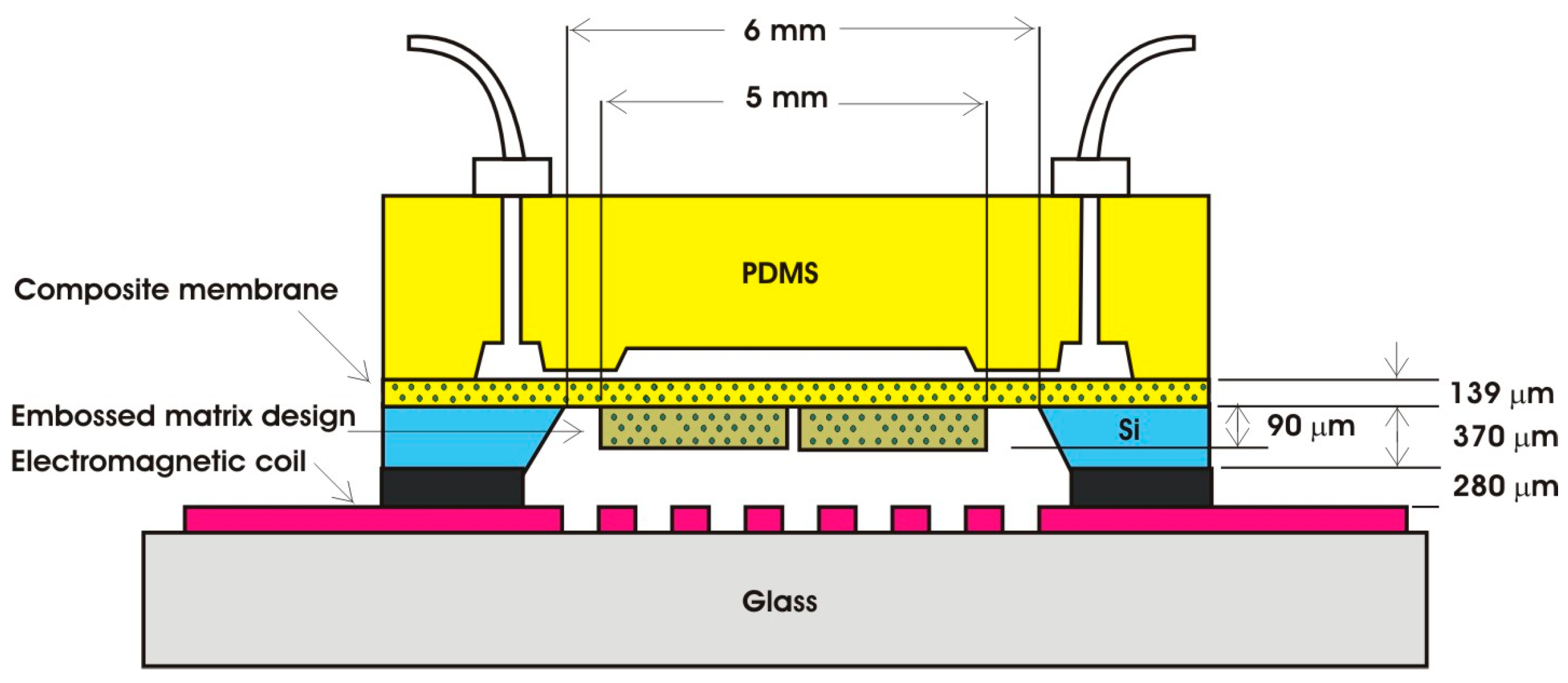
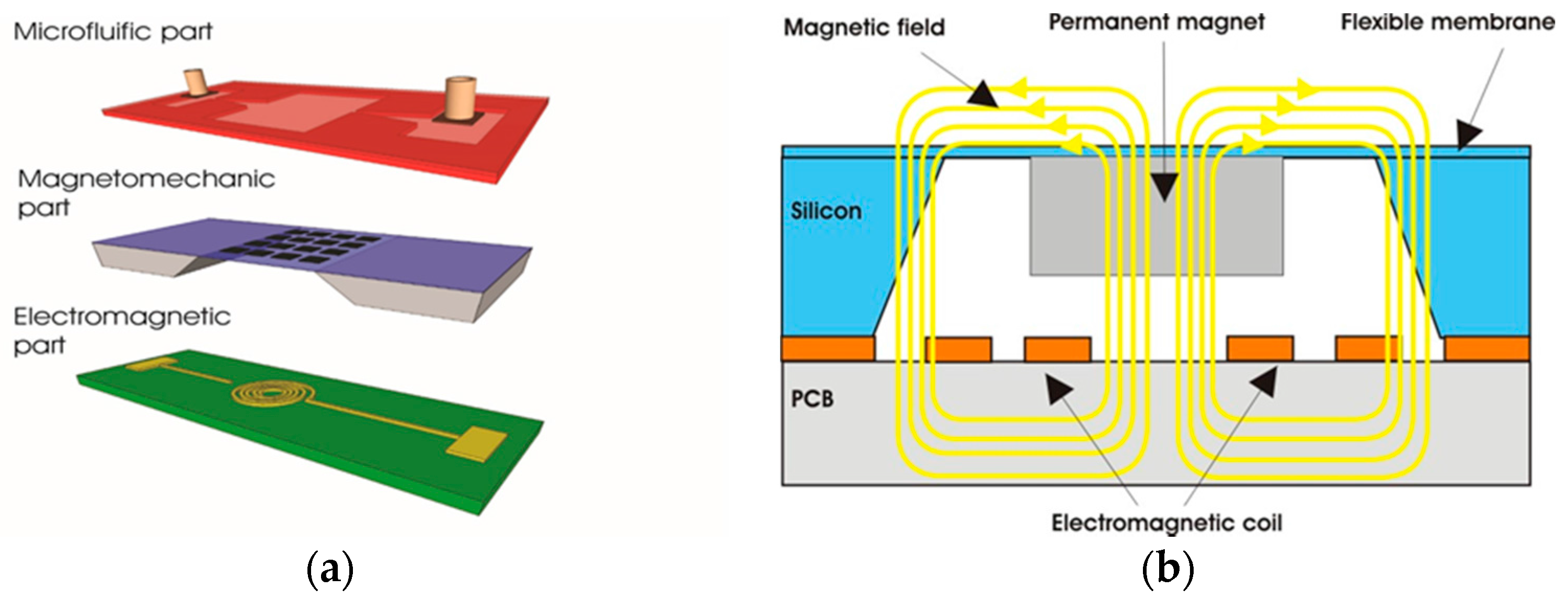
The EM micropump consists of three main components: a microfluidic component, a magnetomechanic actuator, and an electromagnetic component, as shown in
Figure 1a. Studies on the microfluidic and electromagnetic components have been reported elsewhere [
2,
18,
21,
22,
23]. Therefore, the design of the microcoil, the microfluidic channel, and the chamber will not be discussed in this paper. We focus on the improvement of the magnetomechanic actuator that consists of a permanent magnet and a deformable mechanical membrane that is responsive to the magnetic field generated by the electromagnetic coil. Theoretically, when a magnetic field generated by a microcoil interacts with the magnet particles embedded in the membrane composite, it produces force that causes the composite membrane to deform periodically (
Figure 1b) [
1,
15].
The push–pull action of the membrane in the pump chamber will create a pressure change in the chamber and allow for the transport of the fluids from the inlet to the chamber. The direction of the fluidic flow is determined by the diffuser and nozzle design [
14,
24,
25].
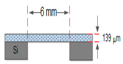
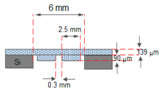
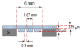
Figure 2 shows the design specification of the proposed EM micropump consisting of a matrix-patterned mold structure attached to a silicon substrate and bonded with the PDMS-based microfluidic component. The membrane and the microfluidic component are integrated with the electromagnetic coil to complete the micropump system.
Table 1 shows the specific embossed matrix design of the membrane. Two matrix structure types, namely, square flat and square shapes with dimensions of (1 × 1), (2 × 2), or (3 × 3), were designed to observe the effects of the matrix combination on the deformation capability of the membrane.
2.1. Synthesis of Magnetic Polymer Composite Membrane
The polymer was made with a SYLGARD® 184 silicon elastomer kit (Dow Corning, Midland, MI, USA) containing PDMS and curing agent, mixed at a 10:1 ratio. The PDMS mixture was then mixed with 6% NdFeB magnetic particles using a mechanical stirrer.
After the mixing process, the composite magnetic polymer was spin-coated onto a pre-developed SU8 matrix mold structure. The spin coater machine was set at 500 rpm for 10 s to spread the composite. The composite was then ramped up to a higher speed of 800 rpm for 20 s to obtain a membrane thickness of ~139 µm. A thinner membrane layer could be obtained by increasing the coating speed. The spin-coated composite material was finally hard-cured at 60 °C for 30 min to completely remove the remaining water content.
2.2. Magnetic Properties of Magnetic Polymer Composite
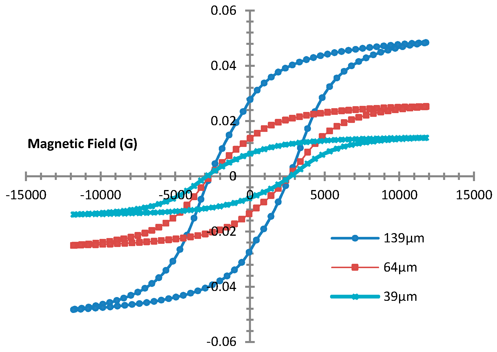
The magnetic property of the polymer composite was studied by analyzing the hysteresis curve using a vibration sample magnetometer (VSM).
Figure 3 shows the hysteresis loop of synthesized PDMS:NdFeB at room temperature and with a magnetization of 1.2 T and a 6% mixture composition, found to be the optimum composition [
26]. It can be seen that the magnetic property still exists in the magnetic composite material at different thicknesses.
It can be seen that the layer thickness has a significant effect on the magnetic properties of the composite material. This is probably due to the amount of magnetic particles contained in the polymer matrix. The thicker the layer, the greater the magnetization can be. A 139 µm membrane thickness shows a saturated remanence magnet of 37.637 mT. The coercivity value of the polymer composite is about 2720 G, which is the force required to produce a zero magnetism in a material.
2.3. Electro-Mechanical Properties of Magnetic Composite Membrane
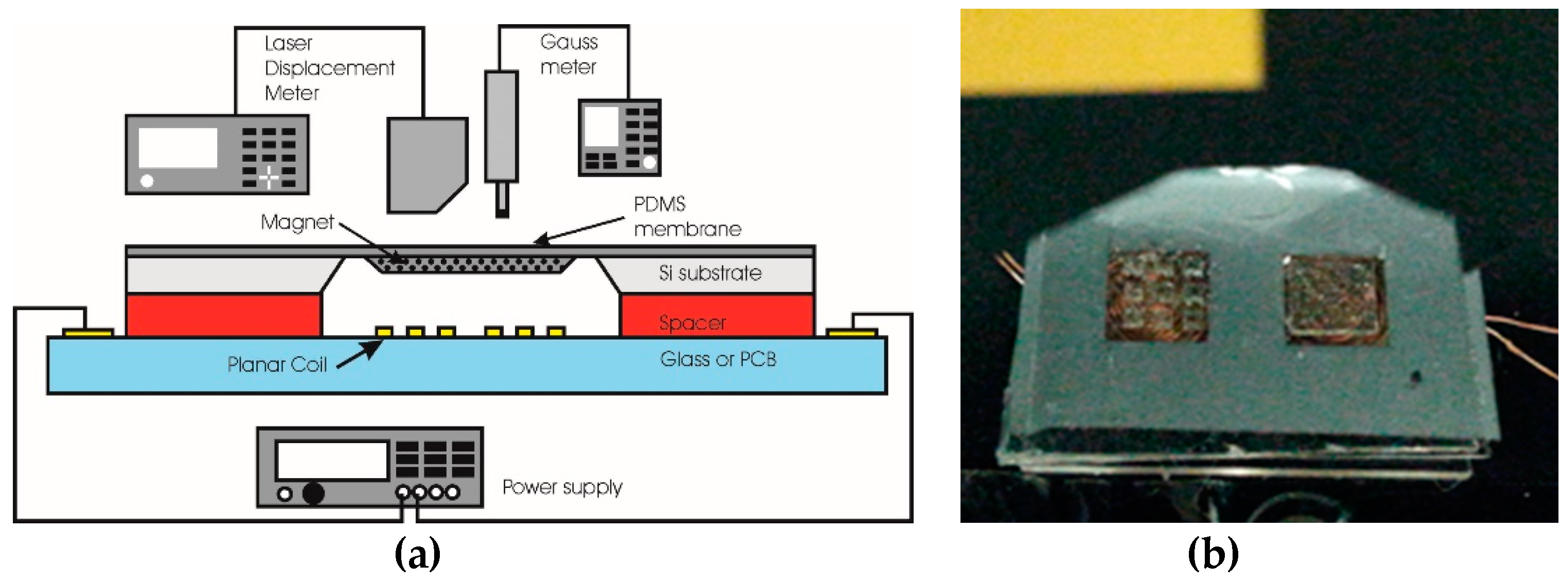
To evaluate the electromechanical properties of the magnetic composite membrane, a membrane deflection test using a laser displacement meter was conducted in open air (without the attachment of the microfluidic component). The measurement system consists of a probing stage, a power supply, a Gaussian meter, and a laser displacement meter.
Figure 4 shows the schematic diagram of the membrane deflection measurement setup (a) and the fabricated membrane under the laser probe during the measurement (b).
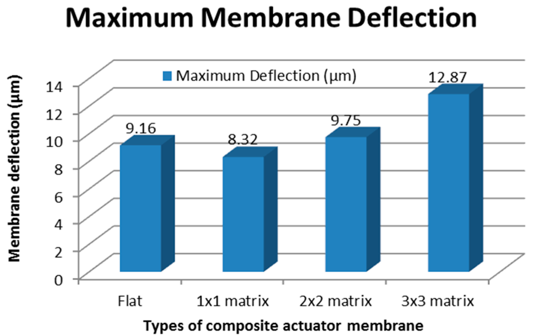
For the test, an alternating current (AC) voltage was applied to the electromagnetic for about 60 s until the membrane gave a steady state response. The composite membrane with a varied embossed matrix structure was then measured. The maximum deflection for all membrane types is plotted in
Figure 5.
Figure 5 clearly shows that the membrane with a 3 × 3 matrix embossed design contributes to the highest deflection of approximately 12.87 µm. The membrane with an embossed 1 × 1 matrix had the lowest deflection value. This is because the membranes with larger embossed matrices are more rigid, which makes them hard to bend. Smaller cubes make the membrane more flexible, and spaces between matrix cubes are utilized during deformation.
These results confirm an early simulation study done where a membrane with a smaller magnet will produce a higher deflection [
27].
3. Pump System Integration
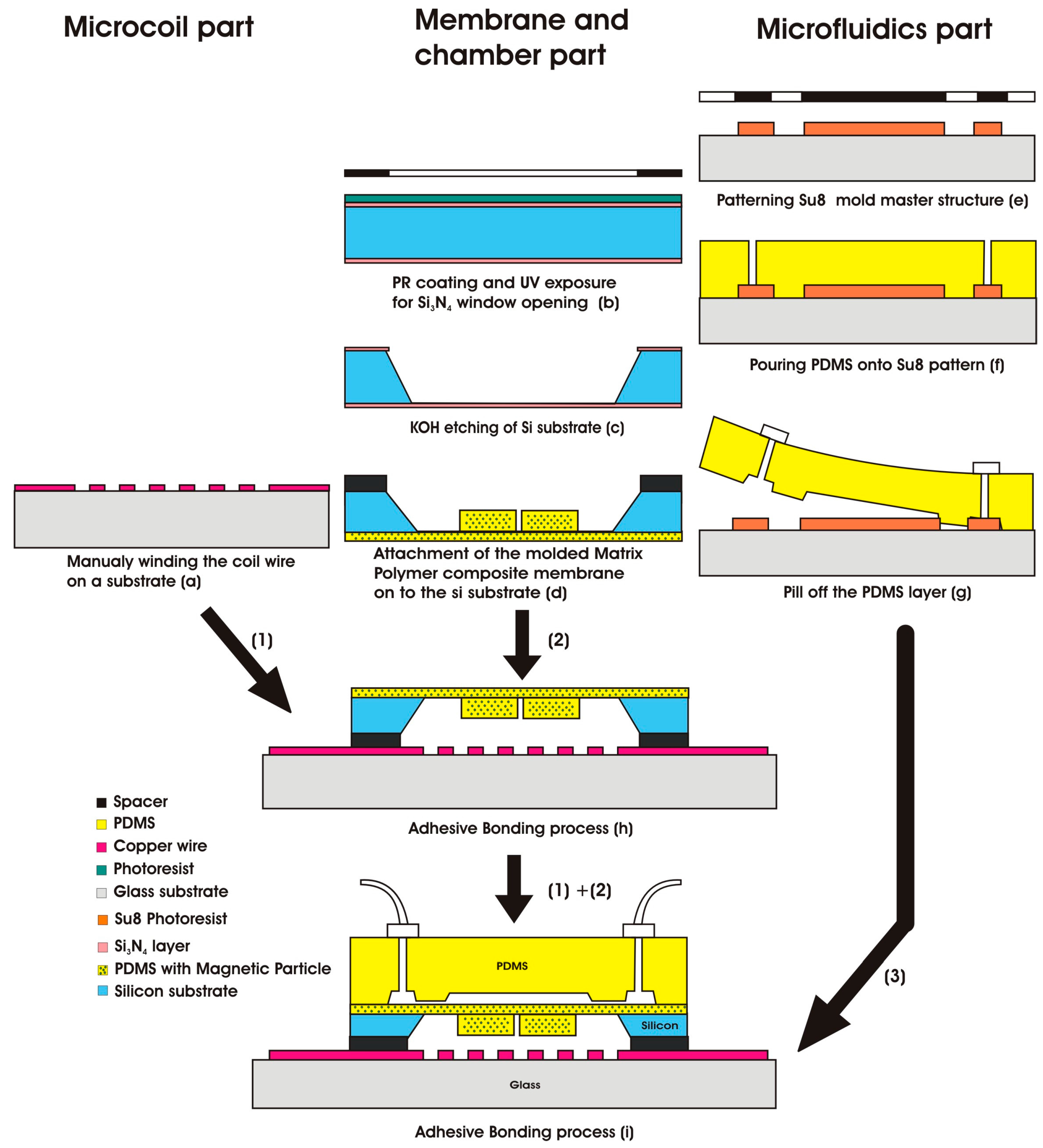
The EM pump was fabricated using a standard MEMS process. The process can be divided into three parts: the electromagnetic component, the magneto-mechanic component, and the microfluidic component. Each component of the system was fabricated separately. The step-by-step fabrication process is shown in
Figure 6.
The process started with the fabrication of an electromagnetic field generator at the bottom of the actuator (Step 1). A planar spiral coil wire was manually wounded and attached to the glass substrate. The coil wire was used to generate a magnetic field that interacts with the permanent magnet. The diameter of the wire core was 160 µm, and the cladding around the core was about 16 µm. The spacing between the composite membrane and coil was about 0.3 mm. A copper coil was then looped in the planar and glued to the top of the glass substrate.
The fabrication of the actuator membrane started with spin coating the synthesized magnetic polymer composite on to a predefined SU8 mold matrix structure on a glass wafer. The coated polymer composite material was then hard-cured in an oven for 30 min at 60 °C. Finally, the cured polymer composite layers were peeled off and transferred to the top silicon wafer, which was hollow and with dimensions of 6 × 6 mm2, to form the actuator membrane (Step 2). To complete the actuator system, the glass wafer with an electromagnetic coil was bonded with the PDMS-based actuator membrane and chamber (Steps 1 and 2).
The microfluidic component was fabricated in a similar way. The process started with pouring the pure PDMS onto a predefined SU8 mold structure. The mold structure was hard-cured and transferred to the actuator membrane surface to form a complete pump system (Step 3).
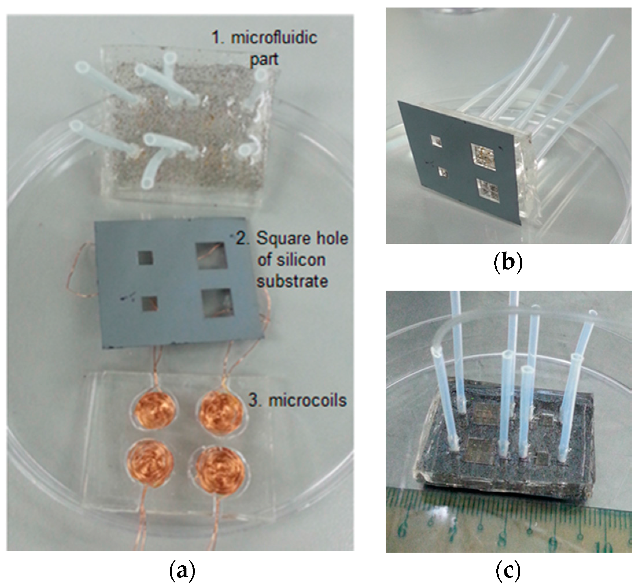
Figure 7a shows the prototype of the developed micropump components before system integration. In
Figure 7b, we can see that the magnetic membrane can be properly transferred to a silicon substrate and is ready for the actuation test.
Figure 7c shows the complete pump structure after the actuator was bonded with the microfluidic component. The leaking test was conducted in order to ensure that there were no leaks in the chamber or the channel.
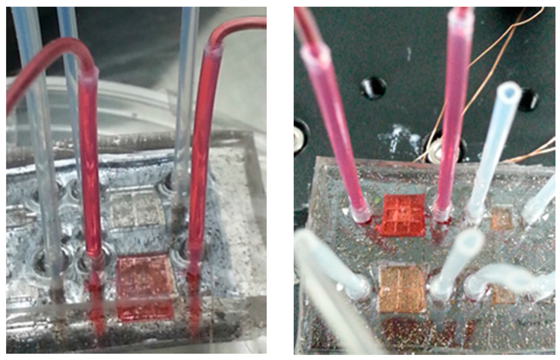
Figure 8 shows a picture of the tested micropump filled with deionized (DI) water colored red. Red DI water was used to make the liquid flow inside the micropump visible for monitoring purposes. It can be seen in the picture that everything works well. No leaking was spotted.
4. Fluid Flow Test of EM Micropump
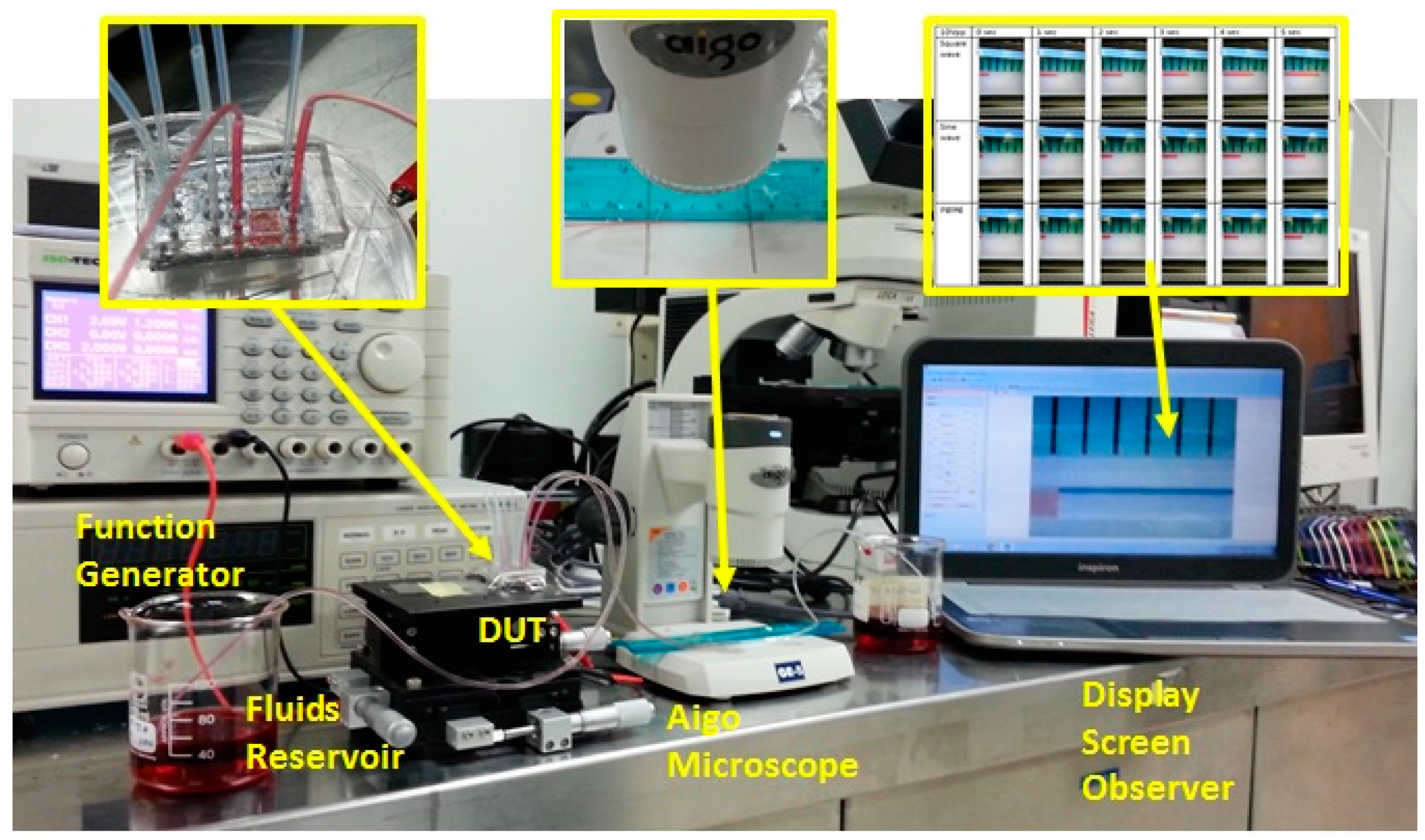
The functionality of the micropump was verified using a fluid flow test through the microfluidic channel. The coil was fed with a continuous AC voltage supply by a function generator with controllable frequency. For the measurement of the micropump flow rate, the liquid flow at the outlet tube was monitored using the Aigo digital microscope (Aigo Digital Technology Co., Ltd., Beijing, China). The experimental set up shown in
Figure 9 consists of fluid sample storage, fluid tubing connecting the sample storage and the pump, the power supply and control, the Aigo microscope, an observer screen, and the fluid storage at the open end of the fluid tubing on the other side of the pump system.
The functionality test of the fabricated EM micropump was performed by analyzing the flow rate through observation of the liquid flow inside the fluidic tubing for 30 min. The fluid flow was then calculated as the distance of fluid traveling through the fluid tubing with a diameter of 0.37 mm in a certain observation time.
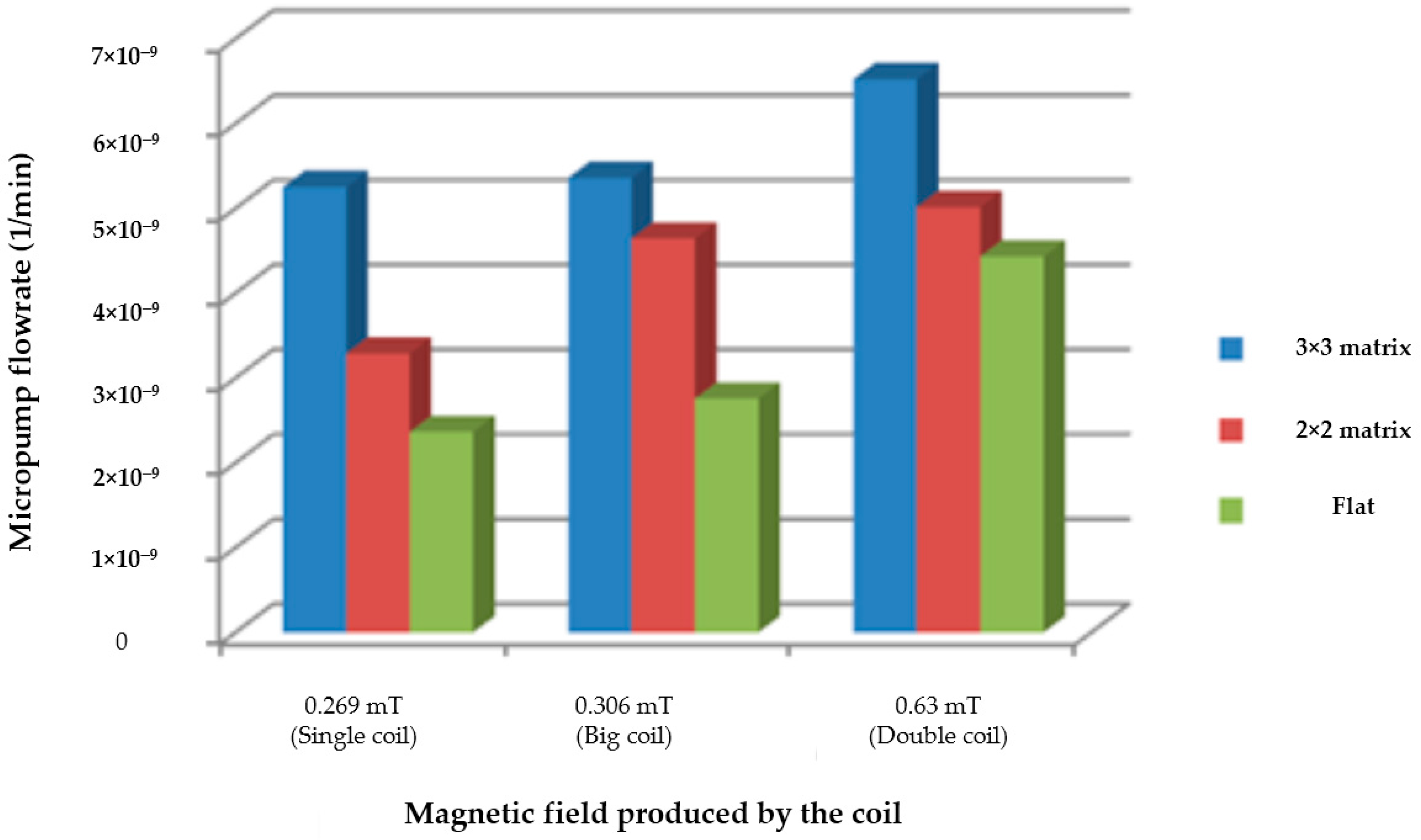
The measurement of the flow rate was taken with the presence of three types of micro-coil, namely, a single planar coil, a larger copper planar coil, and a double planar coil that generates a different magnetic field. The EM micropump with a flat composite membrane and an embossed matrix composite membrane of 3 × 3 and 2 × 2 were tested. An AC supply current from the function generator was fed to the micro-coil. The function generator was set with a 10 Vpp square wave, 0.235 mA, and a 1 Hz operating frequency. The flow rate of each micropump is plotted in the bar graph shown in
Figure 10.
It is clearly seen from
Figure 10 that the micropump with a membrane matrix of 3 × 3 (the blue bar) had the highest flow rate, 6.523 nL/min. The flat composite membrane (the green bar) had the lowest liquid flow rate for all coils. Moreover, the micropump with the double planar coil, compared to the micropumps with a single planar and a larger planar coil, had a higher flow rate. This is because the magnetic field produced by the double coil (0.63 mT) is the highest among all others. As stated in a previous report [
26], the magnetic field generated by the planar electromagnetic coil will directly interact with the permanent magnet and hence produce a magnetic force that pushes and pulls the membrane, allowing for an improved pumping route. These results reflect that a lower membrane deflection will produce a low liquid flow rate.
It can be seen then that the fabricated device was able to deliver fluid at an extremely slow flow rate, below the range reported previously [
6]. It was also shown that the fluid flow characteristic was proportionally related to membrane deformation. Therefore, the injection flow rate could be controlled by adjusting the frequency, the signal type, and the height of the input power supplied to the electromagnetic coil. We showed here that magnetic fields generated by microcoils and a smaller matrix membrane design can be used to significantly control the fluid flow rate of the micropump. Such a controlled flow rate is believed to have very high potential in enhancing fluid injection system capability for continuous drug delivery.
5. Conclusions
In this work, an EM micropump with a matrix composite membrane was successfully designed, fabricated, and tested. The composite is a mixture of PDMS and 6% NdFeB particles and designed to be an embossed matrix membrane for the micropump. The design eradicates the need for bulk magnets, allowing for a more compact and simple design. Embossed matrix membranes of 1 × 1, 2 × 2, and 3 × 3 were built, and the 3 × 3 matrix membrane produced the highest membrane deflection value, 12.87 µm. As a micropump, the 3 × 3 matrix membrane attained the highest flow rate of 6.523 nL/min when the micropump was driven by a double planar coil. The designed EM micropump has been successfully used with nano-dose sample injection and thus is highly desirable for applications that require very high injection resolutions for high accuracy dosages, especially in lab-on-chip and drug delivery systems.
Acknowledgments
This work was supported by the Ministry of Higher Education under Long-term Research Grant Scheme (LRGS Project) Grant No. LRGS/2015/UKM-UKM/NANOMITE/04/01 and Fundamental Research Grant Scheme (FRGS Project) Grant No. FRGS/1/2016/TK05/UKM/02/2.
Author Contributions
J.Y., A.A.H. and B.Y.M. conceived and designed the experiments; J.Y., M.M.S. and B.B. performed the experiments; M.M.S. analyzed the data; M.M.S. contributed reagents/materials/analysis tools; J.Y. and M.M.S. wrote the paper.
Conflicts of Interest
The authors declare no conflict of interest.
References
- Abhari, F.; Jaafar, H.; Yunus, N.A. A comprehensive study of micropumps technologies. Int. J. Electrochem. Sci. 2012, 7, 9765–9780. [Google Scholar]
- Ashraf, M.W.; Tayyaba, S.; Afzulpurkar, N. Micro electromechanical systems (MEMS) based microfluidic devices for biomedical applications. Int. J. Mol. Sci. 2011, 12, 3648–3704. [Google Scholar] [CrossRef] [PubMed]
- Woias, P. Micropumps—Past, progress and future prospects. Sens. Actuators B 2005, 105, 28–38. [Google Scholar] [CrossRef]
- Aj, M.Z.; Patil, S.K.; Baviskar, D.T.; Jain, D.K. Implantable drug delivery system: A review. Int. J. Pharm. Tech. Res. 2012, 4, 280–292. [Google Scholar]
- Nisar, A.; Afzulpurkar, N.; Mahaisavariya, B.; Tuantranont, A. MEMS-based micropumps in drug delivery and biomedical applications. Sens. Actuators B Chem. 2008, 130, 917–942. [Google Scholar] [CrossRef]
- Amirouche, F.; Zhou, Y.; Johnson, T. Current micropump technologies and their biomedical applications. J. Microsyst. Technol. 2009, 15, 647–666. [Google Scholar] [CrossRef]
- Bhailıs, D.; De Murray, C.; Duffy, M.; Alderman, J.; Kelly, G. Modelling and analysis of a magnetic microactuator. Sens. Actuators 2000, 81, 285–289. [Google Scholar] [CrossRef]
- Koch, M.; Harris, N.; Evans, A.G.R.; White, N.M.; Brunnschweiler, A. A novel micromachined pump based on thick-film piezoelectricactuation. In Proceedings of the International Solid State Sensors and Actuators Conference (Transducers ’97), Chicago, IL, USA, 16–19 June 1997. [Google Scholar]
- Morkved, T.L.; Lopes, W.A.; Hahm, J.; Sibener, S.J.; Jaeger, H.M. Silicon nitride membrane substrates for the investigation of local structure in. J. Polym. 1998, 39, 3871–3875. [Google Scholar] [CrossRef]
- Petersen, K.E. Silicon as a Mechanical Material. Proc. IEEE 1982, 70, 420–457. [Google Scholar] [CrossRef]
- Venstra, W.J.; Sarro, P.M. Fabrication of crystalline membranes oriented in the (111) plane in a (100) silicon wafer. Microelectron. Eng. 2003, 68, 502–507. [Google Scholar] [CrossRef]
- Pan, T.; Kai, E.; Stay, M.; Barocas, V.; Ziaie, B. A magnetically driven PDMS peristaltic micropump. In Proceedings of the Annual International Conference of the IEEE Engineering in Medicine and Biology Society, San Francisco, CA, USA, 1–5 September 2004; Volume 4, pp. 2639–2642. [Google Scholar]
- Yin, H.; Huang, Y.; Fang, W.; Hsieh, J. A novel electromagnetic elastomer membrane actuator with a semi-embedded coil. Sens. Actuators A 2007, 139, 194–202. [Google Scholar] [CrossRef]
- Zhou, Y.; Amirouche, F. An Electromagnetically-actuated all-PDMS valveless micropump for drug delivery. Micromachines 2011, 2, 345–355. [Google Scholar] [CrossRef]
- Chang, H.-T.; Lee, C.-Y.; Wen, C.-Y. Design and Modeling of a Mems-Based Valveless Pump Driven by an Electromagnetic Force. In Proceedings of the DTIP of MEMS & MOEMS 2006, Rome, Italy, 26–28 April 2006. [Google Scholar]
- Cho, H.J.; Ahn, C.H. A bidirectional magnetic microactuator using electroplated permanent magnet arrays. J. Microelectromech. Syst. 2002, 11. [Google Scholar] [CrossRef]
- Su, Y.; Chen, W. Investigation on electromagnetic microactuator and its application in Micro-Electro-Mechanical System (MEMS). In Proceedings of the 2007 IEEE International Conference on Mechatronics and Automation, ICMA 2007, Harbin, China, 5–8 August 2007; pp. 3250–3254. [Google Scholar] [CrossRef]
- Bahadorimehr, A.R.; Jumril, Y.; Majlis, B.Y. Low cost fabrication of microfluidic microchannels for Lab-On-a-Chip applications. In Proceedings of the 2010 International Conference on Electronic Devices, Systems and Applications, ICEDSA 2010, Kuala Lumpur, Malaysia, 11–14 April 2010; pp. 242–244. [Google Scholar] [CrossRef]
- Masrie, M.; Majlis, B.Y.; Yunas, J. Experimental analysis on SU8-micromolding structure of PDMS (poly-dimethylsiloxane) based microfluidic channel Experimental Analysis on SU8-Micromolding Structure of PDMS (Poly-Dimethylsiloxane) Based Microfluidic Channel. In Proceedings of the IEEE International Conference on Semiconductor Electronics (ICSE), Kuala Lumpur, Malaysia, 27–29 August 2014; pp. 115–118. [Google Scholar] [CrossRef]
- Shan, C.; Chen, F.; Yang, Q.; Li, Y.; Hou, X. High-level integration of three-dimensional microcoils array in fused silica. Opt. Lett. 2015, 40, 4050–4053. [Google Scholar] [CrossRef] [PubMed]
- Isiksacan, Z.; Guler, M.T.; Aydogdu, B.; Bilican, I. Rapid fabrication of microfluidic PDMS devices from reusable PDMS molds using laser ablation. J. Micromech. Microeng. 2016, 26. [Google Scholar] [CrossRef]
- Pawinanto, R.E.; Yunas, J.; Majlis, B.Y.; Badariah, B.; Muzalifah, M.M. Fabrication and testing of electromagentic MEMS mcroactuator utilizing PCB based microcoil. ARPN J. Eng. Appl. Sci. 2015, 10, 8399–8493. [Google Scholar]
- Wu, J.J.; Bernstein, G.H. An inlaid electroplated copper coil for on-chip powering of microelectromechanical systems devices. J. Vac. Sci. Technol. B 2004, 22, 611–618. [Google Scholar] [CrossRef]
- Dich, N.Q.; Dinh, T.X.; Pham, P.H.; Dau, V.T. Study of valveless electromagnetic micropump by volume-of-fluid and OpenFOAM. Jpn. J. Appl. Phys. 2015, 54. [Google Scholar] [CrossRef]
- Oh, K.W.; Ahn, C.H. TOPICAL REVIEW: A review of microvalves. J. Micromech. Microeng. 2006, 16. [Google Scholar] [CrossRef]
- Said, M.M.; Yunas, J.; Pawinanto, R.E.; Majlis, B.Y. Physical PDMS based electromagnetic actuator membrane with embedded magnetic particles in polymer composite. Sens. Actuators A Phys. 2016, 245, 85–96. [Google Scholar] [CrossRef]
- Said, M.M.; Yunas, J.; Majlis, B.Y.; Bais, B.; Hamzah, A.A. Design and optimization of magnetic particles embedded in PDMS membrane. In Proceedings of the 2013 IEEE Regional Symposium on Micro and Nano Electronics, Langkawi, Malaysia, 25–27 September 2013; pp. 21–24. [Google Scholar] [CrossRef]
© 2017 by the authors. Licensee MDPI, Basel, Switzerland. This article is an open access article distributed under the terms and conditions of the Creative Commons Attribution (CC BY) license (http://creativecommons.org/licenses/by/4.0/).


