
Magnetic Actuation Based Motion Control for Microrobots: An Overview


Abstract
:1. Introduction
2. Magnetic Actuation: Forces and Torques
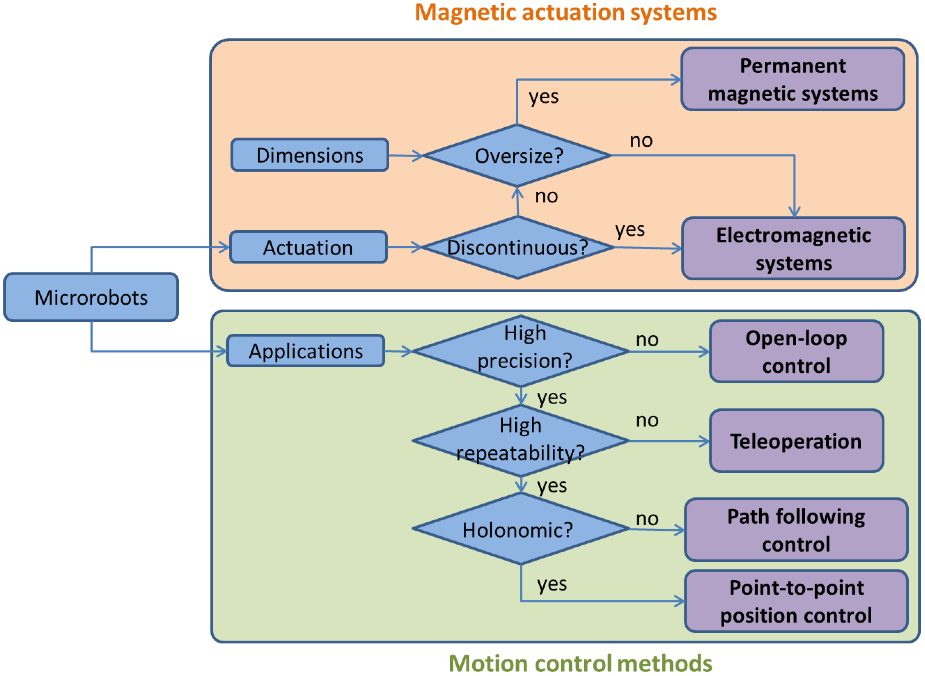
3. Magnetic Actuation Systems
3.1. Electromagnetic Actuation Systems


| Scope | Composition | Application | DoF | Reference |
|---|---|---|---|---|
| Uniform field | 3D Helmholtz coils | uniform rotating magnetic field | 3 (3R) | [36,41,45,47] |
| square wave oscillating field | [48] | |||
| On/Off magnetic field | [49,50] | |||
| conical magnetic field | [51] | |||
| Magnetic gradient | Uniform saddle coils | uniform magnetic field | 1 (1R) | [53] |
| OctoMag | motion control in 3D space | 5 (2R + 3T) | [35] | |
| MiniMag | motion control in 3D space | 5 (2R + 3T) | [60] | |
| Independently controlled electromagnets | motion control in 3D space | 6 (3R + 3T) | [61,62] | |
| Combined magnetic fields | Gradient saddle coils | Magnetic field gradient | 1 (1T) | [53] |
| One pair of Helmholtz coils + one pair of Maxwell coils + motorf | motion control in 2D plane | 3 (1R + 2T) | [55] | |
| Two pairs of Helmholtz coils + two pairs of Maxwell coils | motion control in 2D plane | 3 (1R + 2T) | [56,57] | |
| Two pairs of Helmholtz coils | motion control in 2D plane (Helmholtz currents ≥ torques + anti-Helmholtz currents ≥ forces) | 3 (1R + 2T) | [58] | |
| One pair of Helmholtz coils + one pair of saddle coils + motor | motion control in 2D plane | 3 (2R + 1T) | [59] |
3.2. Rotating Permanent Magnetic Systems

4. Motion Control
4.1. Open-Loop Control


4.2. Closed-Loop Control


| Microrobots | Actuation | Control | Reference |
|---|---|---|---|
| Holonomic | Pulling by magnetic gradient | Pre-programmed open-loop control | [55] |
| Point to point closed-loop position control | [35,84] | ||
| Stick-slip motion by oscillating fields | Point to point closed-loop position control | [83] | |
| Non-holonomic | Helical propulsion by rotating fields | Pre-programmed open-loop control | [36,37,73] |
| Open-loop teleoperation | [78] | ||
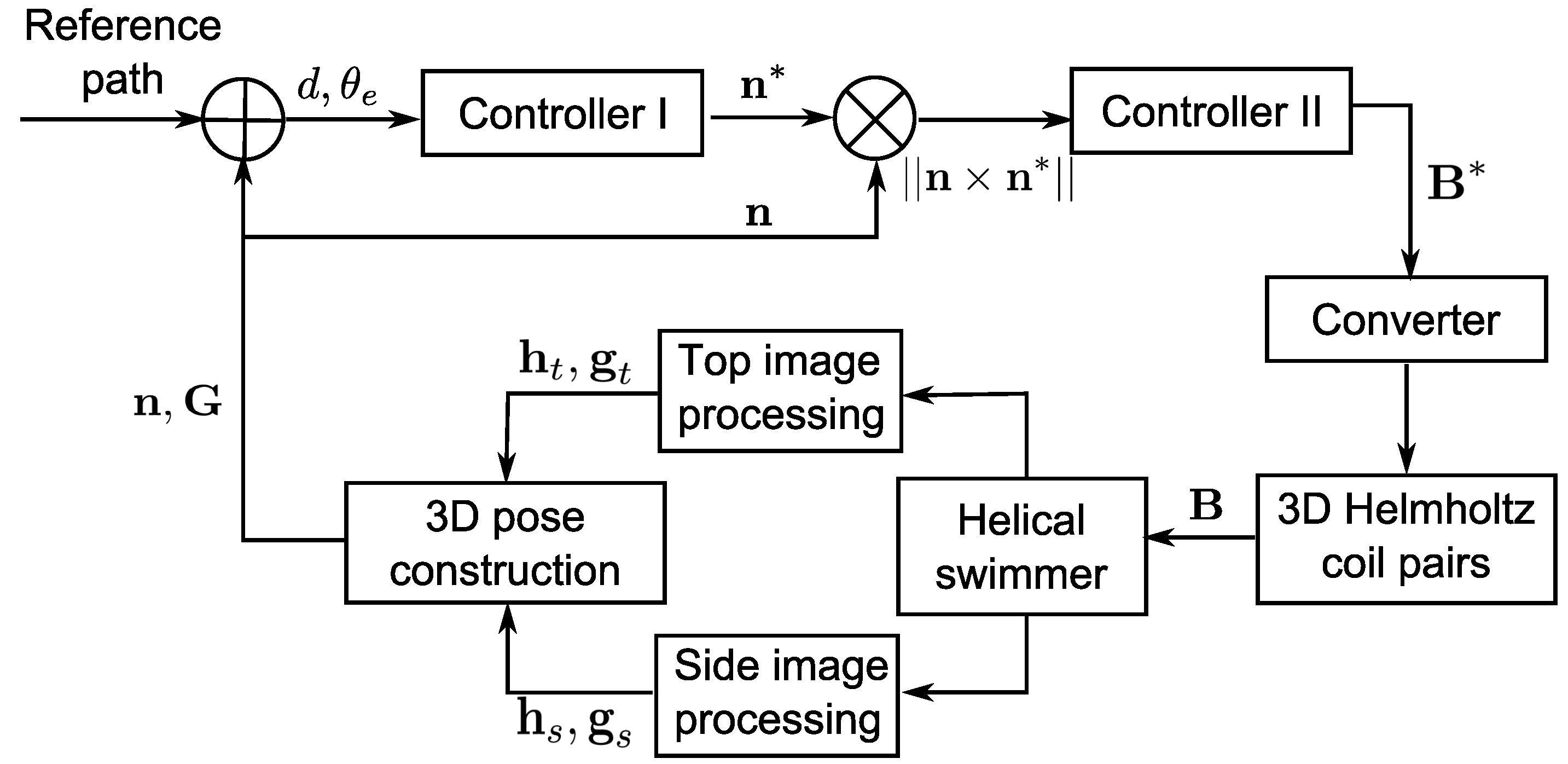
| Closed-loop planar path following | [43] | ||
| Drilling by rotating fields and pulling by gradient | Pre-programmed open-loop control | [74] | |
| Undulatory swimming | Pre-programmed open-loop control | [75] | |
| Clawing motion by oscillating fields | Pre-programmed open-loop control | [76] | |
| Rolling motion by rotating fields | Closed-loop planar path following | [87] | |
| Closed-loop planar trajectory following | [88] |
4.3. Challenges in Motion Control of Microrobots
5. Discussions and Conclusions
Acknowledgments
Author Contributions
Conflicts of Interest
References
- Abbott, J.; Nagy, Z.; Beyeler, F.; Nelson, B. Robotics in the Small, Part I: Microbotics. IEEE Rob. Autom Mag. 2007, 14, 92–103. [Google Scholar] [CrossRef]
- Abbott, J.; Cosentino Lagomarsino, M.; Zhang, L.; Dong, L.; Nelson, B. How Should Microrobots Swim? Int. J. Rob. Res. 2009, 28, 1434–1447. [Google Scholar] [CrossRef]
- Sitti, M. Miniature devices: Voyage of the microrobots. Nature 2009, 458, 1121–1122. [Google Scholar] [CrossRef] [PubMed]
- Nelson, B.; Kaliakatsos, I.; Abbott, J. Microrobots for Minimally Invasive Medicine. Annu. Rev. Biomed. Eng. 2010, 12, 55–85. [Google Scholar] [CrossRef] [PubMed]
- Gauthier, M.; Régnier, S. Robotic Micro-Assembly; IEEE Press: Piscataway, NJ, USA, 2010. [Google Scholar]
- Qiu, F.; Zhang, L.; Tottori, S.; Marquardt, K.; Krawczyk, K.; Franco-Obregón, A.; Nelson, B.J. Bio-inspired microrobots. Mater. Today 2012, 15, 463. [Google Scholar] [CrossRef]
- Chaillet, N.; Régnier, S. Microrobotics for Micromanipulation; Wiley-ISTE: Hoboken, NJ, USA, 2013. [Google Scholar]
- Peyer, K.; Zhang, L.; Nelson, B. Bio-inspired magnetic swimming microrobots for biomedical applications. Nanoscale 2013, 5, 1259–1272. [Google Scholar] [CrossRef] [PubMed]
- Sitti, M.; Ceylan, H.; Hu, W.; Giltinan, J.; Turan, M.; Yim, S.; Diller, E. Biomedical Applications of Untethered Mobile Milli/Microrobots. Proc. IEEE 2015, 103, 205–224. [Google Scholar] [CrossRef]
- Ferreira, A.; Cassier, C.; Hirai, S. Automatic microassembly system assisted by vision servoing and virtual reality. IEEE/ASME Trans. Mechatron. 2004, 9, 321–333. [Google Scholar] [CrossRef]
- Xie, H.; Régnier, S. High-efficiency automated nanomanipulation with parallel imaging/manipulation force microscopy. IEEE Trans. Nanotechnol. 2012, 11, 21–33. [Google Scholar] [CrossRef]
- Bolopion, A.; Xie, H.; Haliyo, S.; Régnier, S. Haptic Teleoperation for 3D Microassembly of Spherical Objects. IEEE/ASME Trans. Mechatron. 2012, 17, 116–127. [Google Scholar] [CrossRef]
- Fukuda, T.; Ueyama, T. Cellular Robotics and Micro Robotic Systems; World Scientific: Singapore, 1994; Voloum 10. [Google Scholar]
- Truper, T.; Kortschack, A.; Jahnisch, M.; Hulsen, H.; Fatikow, S. Transporting cells with mobile microrobots. IET Proc. Nanobiotechnol. 2004, 151, 145–150. [Google Scholar] [CrossRef] [PubMed]
- Suter, M.; Zhang, L.; Siringil, E.C.; Peters, C.; Luehmann, T.; Ergeneman, O.; Peyer, K.E.; Nelson, B.J.; Hierold, C. Superparamagnetic microrobots: Fabrication by two-photon polymerization and biocompatibility. Biomed. Microdevices 2013, 15, 997–1003. [Google Scholar] [CrossRef] [PubMed]
- Feng, L.; Hagiwara, M.; Uvet, H.; Yamanish, Y.; Kawahara, T.; Kosuge, K.; Arai, F. High-speed delivery of microbeads in microchannel using magnetically driven microtool. In Proceedings of the 16th International Conference on Solid-State Sensors, Actuators and Microsystems (TRANSDUCERS), Beijing, China, 5–9 June 2011; pp. 1312–1315.
- Hagiwara, M.; Kawahara, T.; Iijima, T.; Yamanishi, Y.; Arai, F. High speed microrobot actuation in a microfluidic chip by levitated structure with riblet surface. In Proceedings of the IEEE International Conference on Robotics and Automation (ICRA), St. Paul, MN, USA, 14–18 May 2012; pp. 2517–2522.
- Hagiwara, M.; Kawahara, T.; Iijima, T.; Arai, F. High-Speed Magnetic Microrobot Actuation in a Microfluidic Chip by a Fine V-Groove Surface. IEEE Trans. Rob. 2013, 29, 363–372. [Google Scholar] [CrossRef]
- Sanchez, S.; Solovev, A.; Harazim, S.; Schmidt, O. Microbots Swimming in the Flowing Streams of Microfluidic Channels. J. Am. Chem. Soc. 2011, 133, 701–703. [Google Scholar] [CrossRef] [PubMed]
- Hwang, G.; Ivan, I.A.; Agnus, J.; Salmon, H.; Alvo, S.; Chaillet, N.; Régnier, S.; Haghiri-Gosnet, A.M. Mobile microrobotic manipulator in microfluidics. Sens. Actuators A Phys. 2013, 215, 56–64. [Google Scholar] [CrossRef]
- Gao, W.; Wang, J. The environmental impact of micro/nanomachines: A review. ACS Nano 2014, 8, 3170–3180. [Google Scholar] [CrossRef] [PubMed]
- Kim, S.; Qiu, F.; Kim, S.; Ghanbari, A.; Moon, C.; Zhang, L.; Nelson, B.J.; Choi, H. Fabrication and Characterization of Magnetic Microrobots for Three-Dimensional Cell Culture and Targeted Transportation. Adv. Mater. 2013, 25, 5863–5868. [Google Scholar] [CrossRef] [PubMed]
- Peyer, K.; Siringil, E.; Zhang, L.; Nelson, B. Magnetic polymer composite artificial bacterial flagella. Bioinspiration Biomim. 2014, 9, 046014. [Google Scholar] [CrossRef] [PubMed]
- Zhang, L.; Petit, T.; Peyer, K.E.; Nelson, B.J. Targeted cargo delivery using a rotating nickel nanowire. Nanomed. Nanotechnol. Biol. Med. 2012, 8, 1074–1080. [Google Scholar] [CrossRef] [PubMed]
- Yan, X.; Zhou, Q.; Yu, J.; Xu, T.; Yan, D.; Tang, T.; Feng, Q.; Bian, L.; Zhang, Y.; Ferreira, A.; Zhang, L. Magnetite Nanostructured Porous Hollow Helical Microswimmers for Targeted Delivery. Adv. Funct. Mater. 2015, 25, 5333–5342. [Google Scholar] [CrossRef]
- Kharboutly, M.; Gauthier, M.; Chaillet, N. Modeling the Trajectory of a Microparticle in a Dielectrophoresis Device. J. Appl. Phys. 2009, 106, 114312–114317. [Google Scholar] [CrossRef]
- Kosa, G.; Shoham, M.; Zaaroor, M. Propulsion Method for Swimming Microrobots. IEEE Trans. Rob. 2007, 23, 137–150. [Google Scholar] [CrossRef]
- Liew, L.A.; Bright, V.M.; Dunn, M.L.; Daily, J.W.; Raj, R. Development of SiCN ceramic thermal actuators. In Proceedings of the 15th IEEE International Conference on Micro Electro Mechanical Systems, Las Vegas, NV, USA, 20–24 January 2002; pp. 590–593.
- Hwang, G.; Braive, R.; Couraud, L.; Cavanna, A.; Abdelkarim, O.; Robert-Philip, I.; Beveratos, A.; Sagnes, I.; Haliyo, S.; Régnier, S. Electro-osmotic propulsion of helical nanobelt swimmers. Int. J. Rob. Res. 2011, 30, 806–819. [Google Scholar] [CrossRef]
- Martel, S.; Tremblay, C.C.; Ngakeng, S.; Langlois, G. Controlled manipulation and actuation of micro-objects with magnetotactic bacteria. Appl. Phys. Lett. 2006, 89, 233904. [Google Scholar] [CrossRef]
- Martel, S.; Felfoul, O.; Mathieu, J.B.; Chanu, A.; Tamaz, S.; Mohammadi, M.; Mankiewicz, M.; Tabatabaei, N. MRI-based medical nanorobotic platform for the control of magnetic nanoparticles and flagellated bacteria for target interventions in human capillaries. Int. J. Rob. Res. 2009, 28, 1169–1182. [Google Scholar] [CrossRef] [PubMed]
- Solovev, A.A.; Mei, Y.; Bermúdez Ureña, E.; Huang, G.; Schmidt, O.G. Catalytic Microtubular Jet Engines Self-Propelled by Accumulated Gas Bubbles. Small 2009, 5, 1688–1692. [Google Scholar] [CrossRef] [PubMed]
- Gao, W.; Pei, A.; Wang, J. Water-driven micromotors. ACS Nano 2012, 6, 8432–8438. [Google Scholar] [CrossRef] [PubMed]
- Fahrni, F.; Prins, M.W.; Van IJzendoorn, L.J. Micro-fluidic actuation using magnetic artificial cilia. Lab Chip 2009, 9, 3413–3421. [Google Scholar] [CrossRef] [PubMed]
- Kummer, M.; Abbott, J.; Kratochvil, B.; Borer, R.; Sengul, A.; Nelson, B. OctoMag: An electromagnetic system for 5-DOF wireless micromanipulation. IEEE Trans. Rob. 2010, 26, 1006–1017. [Google Scholar] [CrossRef]
- Zhang, L.; Abbott, J.; Dong, L.; Kratochvil, B.; Bell, D.; Nelson, B. Artificial bacterial flagella: Fabrication and magnetic control. Appl. Phys. Lett. 2009, 94, 064107. [Google Scholar] [CrossRef]
- Ghosh, A.; Fischer, P. Controlled Propulsion of Artificial Magnetic Nanostructured Propellers. Nano Lett. 2009, 9, 2243–2245. [Google Scholar] [CrossRef] [PubMed]
- Peyer, K.E.; Tottori, S.; Qiu, F.; Zhang, L.; Nelson, B.J. Magnetic helical micromachines. Chem. Eur. J. 2013, 19, 28–38. [Google Scholar] [CrossRef] [PubMed]
- Xu, T.; Hwang, G.; Andreff, N.; Regnier, S. Modeling and Swimming Property Characterizations of Scaled-Up Helical Microswimmers. IEEE/ASME Trans. Mechatron. 2014, 19, 1069–1079. [Google Scholar] [CrossRef]
- Ishiyama, K.; Arai, K.; Sendoh, M.; Yamazaki, A. Spiral-type micro-machine for medical applications. In Proceedings of the International Symposium onMicromechatronics and Human Science (MHS), Nagoya, Japan, 22–25 October 2000; pp. 65–69.
- Mahoney, A.; Sarrazin, J.; Bamberg, E.; Abbott, J. Velocity Control with Gravity Compensation for Magnetic Helical Microswimmers. Adv. Rob. 2011, 25, 1007–1028. [Google Scholar] [CrossRef]
- Khalil, I.; Pichel, M.; Abelmann, L.; Misra, S. Closed-loop control of magnetotactic bacteria. Int. J. Rob. Res. 2013, 32, 637–649. [Google Scholar] [CrossRef]
- Xu, T.; Hwang, G.; Andreff, N.; Regnier, S. Planar Path Following of 3-D Steering Scaled-Up Helical Microswimmers. IEEE Trans. Rob. 2015, 31, 117–127. [Google Scholar] [CrossRef]
- Jiles, D. Introduction to Magnetism and Magnetic Materials, 2nd ed.; Chapman and Hall: Boca Raton, FL, USA, 1998. [Google Scholar]
- Sendoh, M.; Yamazaki, A.; Chiba, A.; Soma, M.; Ishiyama, K.; Arai, K. Spiral type magnetic micro actuators for medical applications. In Micro-Nanomechatronics and Human Science, Proceedings of the 4th IEEE International Symposium on Symposium Micro-Nanomechatronics for Information-Based Society, Iijima, Japen, 31 October–3 November 2004; pp. 319–324.
- Zhang, L.; Peyer, K.; Nelson, B. Artificial bacterial flagella for micromanipulation. Lab Chip 2010, 10, 2203–2215. [Google Scholar] [CrossRef] [PubMed]
- Xu, T.; Hwang, G.; Andreff, N.; Régnier, S. Characterization of Three-dimensional Steering for Helical Swimmers. In Proceedings of the ICRA’14 IEEE International Conference on Robotics and Automation, Hong Kong, China, 31 May–7 June 2014; pp. 4045–4051.
- Ko, Y.; Na, S.; Lee, Y.; Cha, K.; Ko, S.; Park, J.; Park, S. A jellyfish-like swimming mini-robot actuated by an electromagnetic actuation system. Smart Mater. Struct. 2012, 21, 057001. [Google Scholar] [CrossRef]
- Gao, W.; Sattayasamitsathit, S.; Manesh, K.; Weihs, D.; Wang, J. Magnetically powered flexible metal nanowire motors. J. Am. Chem. Soc. 2010, 132, 14403–14405. [Google Scholar] [CrossRef] [PubMed]
- Frutiger, D.R.; Vollmers, K.; Kratochvil, B.E.; Nelson, B.J. Small, fast, and under control: Wireless resonant magnetic micro-agents. Int. J. Rob. Res. 2010, 29, 613–636. [Google Scholar] [CrossRef]
- Huang, T.; Qiu, F.; Tung, H.; Chen, X.; Nelson, B.; Sakar, M. Generating mobile fluidic traps for selective three-dimensional transport of microobjects. Appl. Phys. Lett. 2014, 105, 114102. [Google Scholar] [CrossRef]
- Xu, T. Propulsion Characteristics and Visual Servo Control of Scaled-up Helical Microswimmers. Ph.D. Thesis, The Université Pierre et Marie Curie-Paris VI, Paris, France, 2014. [Google Scholar]
- Jeon, S.; Jang, G.; Choi, H.; Park, S. Magnetic navigation system with gradient and uniform saddle coils for the wireless manipulation of micro-robots in human blood vessels. IEEE Trans. Magn. 2010, 46, 1943–1946. [Google Scholar] [CrossRef]
- And, E.D.; Sitti, M. Three-Dimensional Programmable Assembly by Untethered Magnetic Robotic Micro-Grippers. Adv. Funct. Mater. 2014, 24, 4397–4404. [Google Scholar]
- Yesin, K.; Vollmers, K.; Nelson, B. Modeling and control of Untethered Biomicrorobots in a Fluidic environment using Electromagnetic Fields. Int. J. Rob. Res. 2006, 25, 527–536. [Google Scholar] [CrossRef]
- Choi, J.; Choi, H.; Cha, K.; Park, J.O.; Park, S. Two-dimensional locomotive permanent magnet using electromagnetic actuation system with two pairs stationary coils. In Proceedings of the IEEE International Conference on IEEE Robotics and Biomimetics (ROBIO), Guilin, China, 13–19 December 2009; pp. 1166–1171.
- Hu, C.; Tercero, C.; Ikeda, S.; Fukuda, T.; Arai, F.; Negoro, M. Modeling and design of magnetic sugar particles manipulation system for fabrication of vascular scaffold. In Proceedings of the IEEE/RSJ International Conference on IEEE Intelligent Robots and Systems (IROS), San Francisco, CA, USA, 25–30 September 2011; pp. 439–444.
- Kim, J.; Kim, M.; Yoo, J.; Kim, S.J. Novel Motion Modes for 2-D Locomotion of a Microrobot. IEEE Trans. Magn. 2014, 50, 1–5. [Google Scholar] [CrossRef]
- Go, G.; Choi, H.; Jeong, S.; Lee, C.; Ko, S.Y.; Park, J.O.; Park, S. Electromagnetic Navigation System Using Simple Coil Structure (4 Coils) for 3-D Locomotive Microrobot. IEEE Trans. Magn. 2015, 51, 1–7. [Google Scholar] [CrossRef]
- Schuerle, S.; Erni, S.; Flink, M.; Kratochvil, B.E.; Nelson, B.J. Three-Dimensional Magnetic Manipulation of Micro- and Nanostructures for Applications in Life Sciences. IEEE Trans. Magn. 2013, 49, 321–330. [Google Scholar] [CrossRef]
- Pawashe, C.; Floyd, S.; Sitti, M. Modeling and experimental characterization of an untethered magnetic micro-robot. Int. J. Rob. Res. 2009, 28, 1077–1094. [Google Scholar] [CrossRef]
- Diller, E.; Giltinan, J.; Sitti, M. Independent control of multiple magnetic microrobots in three dimensions. Int. J. Rob. Res. 2013, 32, 614–631. [Google Scholar] [CrossRef]
- Vartholomeos, P.; Fruchard, M.; Ferreira, A.; Mavroidis, C. MRI-guided nanorobotic systems for therapeutic and diagnostic applications. Annu. Rev. Biomed. Eng. 2011, 13, 157–184. [Google Scholar] [CrossRef] [PubMed]
- Fountain, T.; Kailat, P.; Abbott, J. Wireless control of magnetic helical microrobots using a rotating-permanent-magnet manipulator. In Proceedings of the IEEE International Conference on Robotics and Automation (ICRA), Anchorage, AK, USA, 3–7 May 2010; pp. 576–581.
- Furlani, E. Permanent Magnet and Electromechanical Devices: Materials, Analysis, and Applications; Electromagnetism, Elsevier Science: Amsterdam, The Netherlands, 2001. [Google Scholar]
- Mahoney, A.; Cowan, D.; Miller, K.; Abbott, J. Control of Untethered Magnetically Actuated Tools Using a Rotating Permanent Magnet in Any Position; IEEE Press: Piscataway, NJ, USA, 2012; pp. 3375–3380. [Google Scholar]
- Mahoney, A.; Abbott, J. Control of untethered magnetically actuated tools with localization uncertainty using a rotating permanent magnet. In Proceedings of the 4th IEEE RAS EMBS International Conference on Biomedical Robotics and Biomechatronics (BioRob), Rome, Italy, 24–27 June 2012; pp. 1632–1637.
- Lee, J.; Kim, B.; Hong, Y. A flexible chain-based screw propeller for capsule endoscopes. Int. J. Precis. Eng. Manuf. 2009, 10, 27–34. [Google Scholar] [CrossRef]
- Xu, T.; Hwang, G.; Andreff, N.; Régnier, S. Scaled-Up Helical Nanobelt Modeling and Simulation at Low Reynolds Numbers. In Proceedings of the ICRA’12 IEEE International Conference on Robotics and Automation, St. Paul, MN, USA, 14–18 May 2012; pp. 4045–4051.
- Mahoney, A.W.; Abbott, J.J. Generating Rotating Magnetic Fields with a Single Permanent Magnet for Propulsion of Untethered Magnetic Devices in a Lumen. IEEE Trans. Rob. 2014, 30, 411–420. [Google Scholar] [CrossRef]
- Mahoney, A.; Abbott, J. Five-degree-of-freedom Manipulation of an Untethered Magnetic Device in Fluid Using a Single Permanent Magnet with Application in Stomach Capsule Endoscopy. Int. J. Rob. Res. 2015. [Google Scholar] [CrossRef]
- Alshafeei, M.; Hosney, A.; Klingner, A.; Misra, S.; Khalil, I.S. Magnetic-based motion control of a helical robot using two synchronized rotating dipole fields. In Proceedings of the 5th IEEE RAS EMBS International Conference on Biomedical Robotics and Biomechatronics, Sao Paulo, Brazil, 12–15 August 2014; pp. 151–156.
- Zhang, L.; Abbott, J.; Dong, L.; Peyer, K.; Kratochvil, B.; Zhang, H.; Bergeles, C.; Nelson, B.J. Characterizing the Swimming Properties of Artificial Bacterial Flagella. Nano Lett. 2009, 9, 3663–3667. [Google Scholar] [CrossRef] [PubMed]
- Jeong, S.; Choi, H.; Cha, K.; Li, J.; Park, J.O.; Park, S. Enhanced locomotive and drilling microrobot using precessional and gradient magnetic field. Sens. Actuators A Phys. 2011, 171, 429–435. [Google Scholar] [CrossRef]
- Diller, E.; Zhuang, J.; Lum, G.Z.; Edwards, M.R.; Sitti, M. Continuously distributed magnetization profile for millimeter-scale elastomeric undulatory swimming. Appl. Phys. Lett. 2014, 104, 174101. [Google Scholar] [CrossRef]
- Nam, J.; Jeon, S.; Kim, S.; Jang, G. Crawling microrobot actuated by a magnetic navigation system in tubular environments. Sens. Actuators A Phys. 2014, 209, 100–106. [Google Scholar] [CrossRef]
- Laumond, J. (Ed.) La Robotique Mobile; Traité IC2, Hermés science: Paris, France, 2001.
- Tottori, S.; Zhang, L.; Qiu, F.; Krawczyk, K.; Franco-Obregon, A.; Nelson, B. Magnetic Helical Micromachines: Fabrication, Controlled Swimming, and Cargo Transport. Adv. Mater. 2012, 24, 811–816. [Google Scholar] [CrossRef] [PubMed]
- Shull, P.; Niemeyer, G. Open-loop bilateral teleoperation for stable force tracking. In Proceedings of the IEEE/RSJ International Conference on Intelligent Robots and Systems (IROS), St. Louis, MO, USA, 11–15 October 2009; pp. 5121–5126.
- Ghosh, A.; Paria, D.; Rangarajan, G.; Ghosh, A. Velocity Fluctuations in Helical Propulsion: How Small Can a Propeller Be. J. Phys. Chem. Lett. 2014, 5, 62–68. [Google Scholar] [CrossRef] [PubMed]
- Peyer, K.; Zhang, L.; Kratochvil, B.; Nelson, B. Non-ideal swimming of artificial bacterial flagella near a surface. In Proceedings of the 2010 IEEE International Conference on Robotics and Automation (ICRA), Anchorage, AK, USA, 3–7 May 2010; pp. 96–101.
- Mahoney, A.; Nelson, N.; Parsons, E.; Abbott, J. Non-ideal behaviors of magnetically driven screws in soft tissue. In Proceedings of the IEEE/RSJ International Conference on IEEE Intelligent Robots and Systems (IROS), Vilamoura-Algarve, Portugal, 7–11 October 2012; pp. 3559–3564.
- Pawashe, C.; Floyd, S.; Diller, E.; Sitti, M. Two-dimensional autonomous microparticle manipulation strategies for magnetic microrobots in fluidic environments. IEEE Trans. Rob. 2012, 28, 467–477. [Google Scholar] [CrossRef]
- Zhang, Z.; Long, F.; Menq, C. Three-Dimensional Visual Servo Control of a Magnetically Propelled Microscopic Bead. IEEE Trans. Rob. 2013, 29, 373–382. [Google Scholar] [CrossRef]
- Bloch, A.; Marsden, J.; Zenkov, D. Nonholonomic Dynamics. Not. AMS 2005, 52, 320–329. [Google Scholar]
- Thuilot, B.; Cariou, C.; Martinet, P.; Berducat, M. Automatic Guidance of a Farm Tractor Relying on a Single CP-DGPS. Auton. Rob. 2002, 13, 53–71. [Google Scholar] [CrossRef]
- Kim, S.J.; Jeon, S.M.; Nam, J.K.; Jang, G.H. Closed-Loop Control of a Self-Positioning and Rolling Magnetic Microrobot on 3D Thin Surfaces Using Biplane Imaging. IEEE Trans. Magn. 2014, 50, 1–4. [Google Scholar] [CrossRef]
- Pieters, R.; Tung, H.W.; Charreyron, S.; Sargent, D.F.; Nelson, B.J. RodBot: A rolling microrobot for micromanipulation. In Proceedings of the IEEE International Conference on IEEE Robotics and Automation (ICRA), Seattle, WA, USA, 26–30 May 2015; pp. 4042–4047.
- Kratochvil, B.E.; Frutiger, D.; Vollmers, K.; Nelson, B.J. Visual servoing and characterization of resonant magnetic actuators for decoupled locomotion of multiple untethered mobile microrobots. In Proceedings of the IEEE Robotics and Automation (ICRA’09), Kobe, Japan, 9 May 2009; pp. 1010–1015.
- Diller, E.; Floyd, S.; Pawashe, C.; Sitti, M. Control of multiple heterogeneous magnetic microrobots in two dimensions on nonspecialized surfaces. IEEE Trans. Rob. 2012, 28, 172–182. [Google Scholar] [CrossRef]
- Erni, S.; Schürle, S.; Fakhraee, A.; Kratochvil, B.E.; Nelson, B.J. Comparison, optimization, and limitations of magnetic manipulation systems. J. Micro-Bio Rob. 2013, 8, 107–120. [Google Scholar] [CrossRef]
© 2015 by the authors; licensee MDPI, Basel, Switzerland. This article is an open access article distributed under the terms and conditions of the Creative Commons Attribution license (http://creativecommons.org/licenses/by/4.0/).
Share and Cite
Xu, T.; Yu, J.; Yan, X.; Choi, H.; Zhang, L. Magnetic Actuation Based Motion Control for Microrobots: An Overview. Micromachines 2015, 6, 1346-1364. https://doi.org/10.3390/mi6091346
Xu T, Yu J, Yan X, Choi H, Zhang L. Magnetic Actuation Based Motion Control for Microrobots: An Overview. Micromachines. 2015; 6(9):1346-1364. https://doi.org/10.3390/mi6091346
Chicago/Turabian StyleXu, Tiantian, Jiangfan Yu, Xiaohui Yan, Hongsoo Choi, and Li Zhang. 2015. "Magnetic Actuation Based Motion Control for Microrobots: An Overview" Micromachines 6, no. 9: 1346-1364. https://doi.org/10.3390/mi6091346
APA StyleXu, T., Yu, J., Yan, X., Choi, H., & Zhang, L. (2015). Magnetic Actuation Based Motion Control for Microrobots: An Overview. Micromachines, 6(9), 1346-1364. https://doi.org/10.3390/mi6091346