
Micromachined Shape-Memory-Alloy Microactuators and Their Application in Biomedical Devices

Abstract
:1. Intro duction
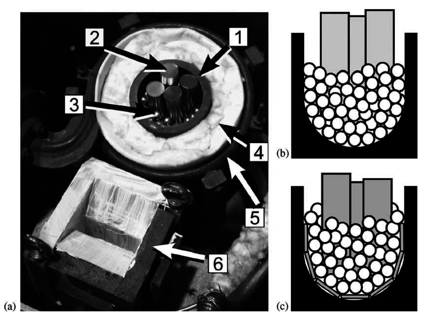
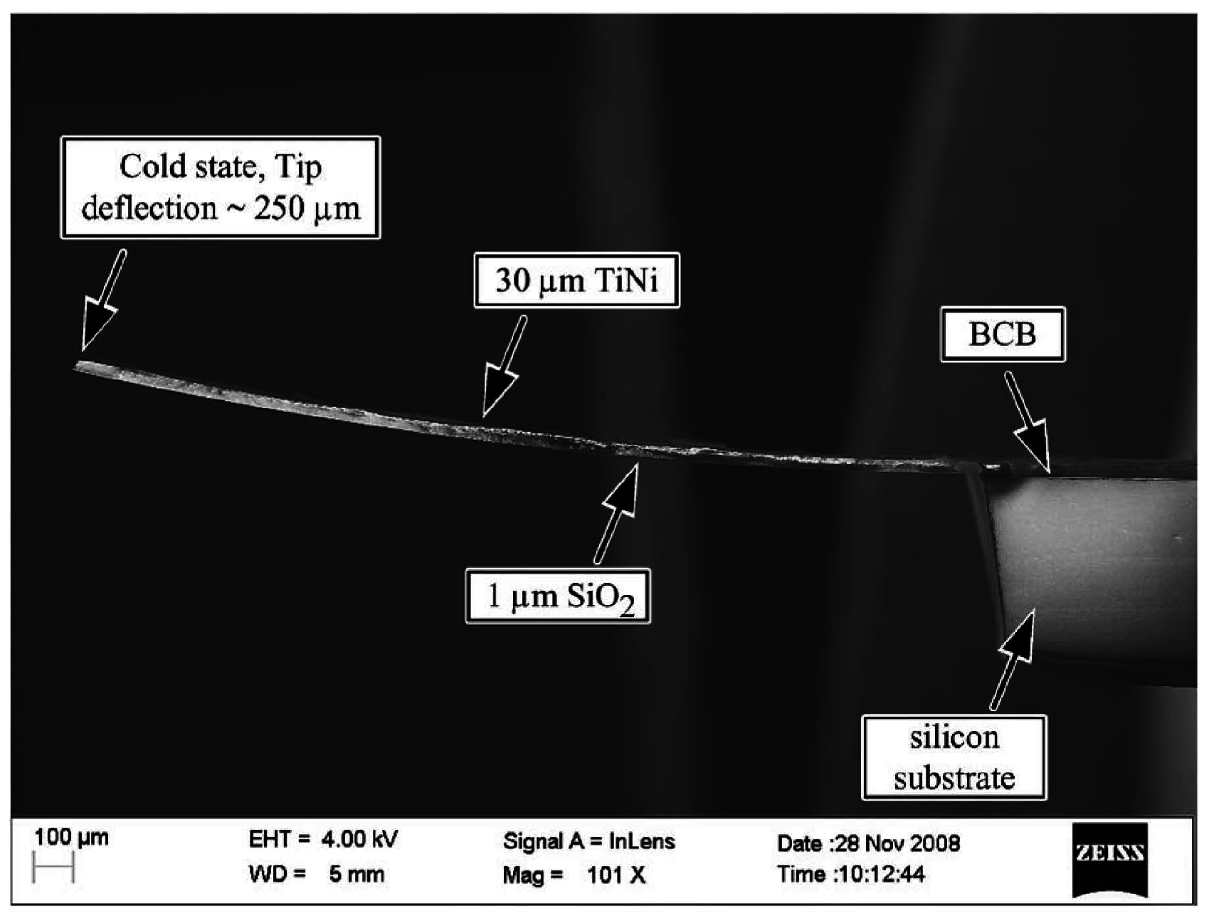
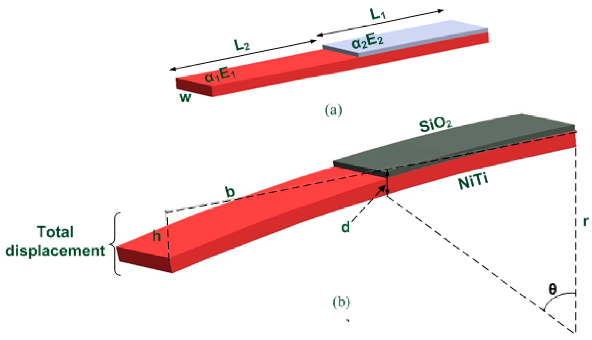
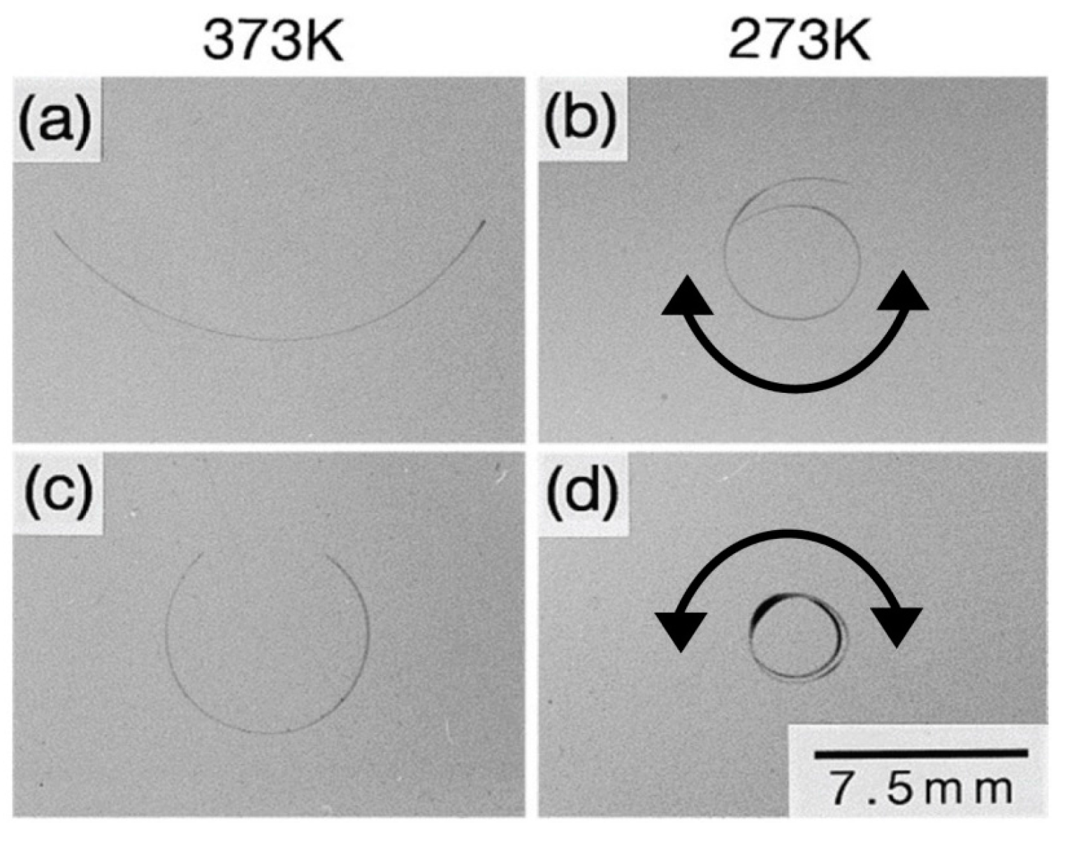
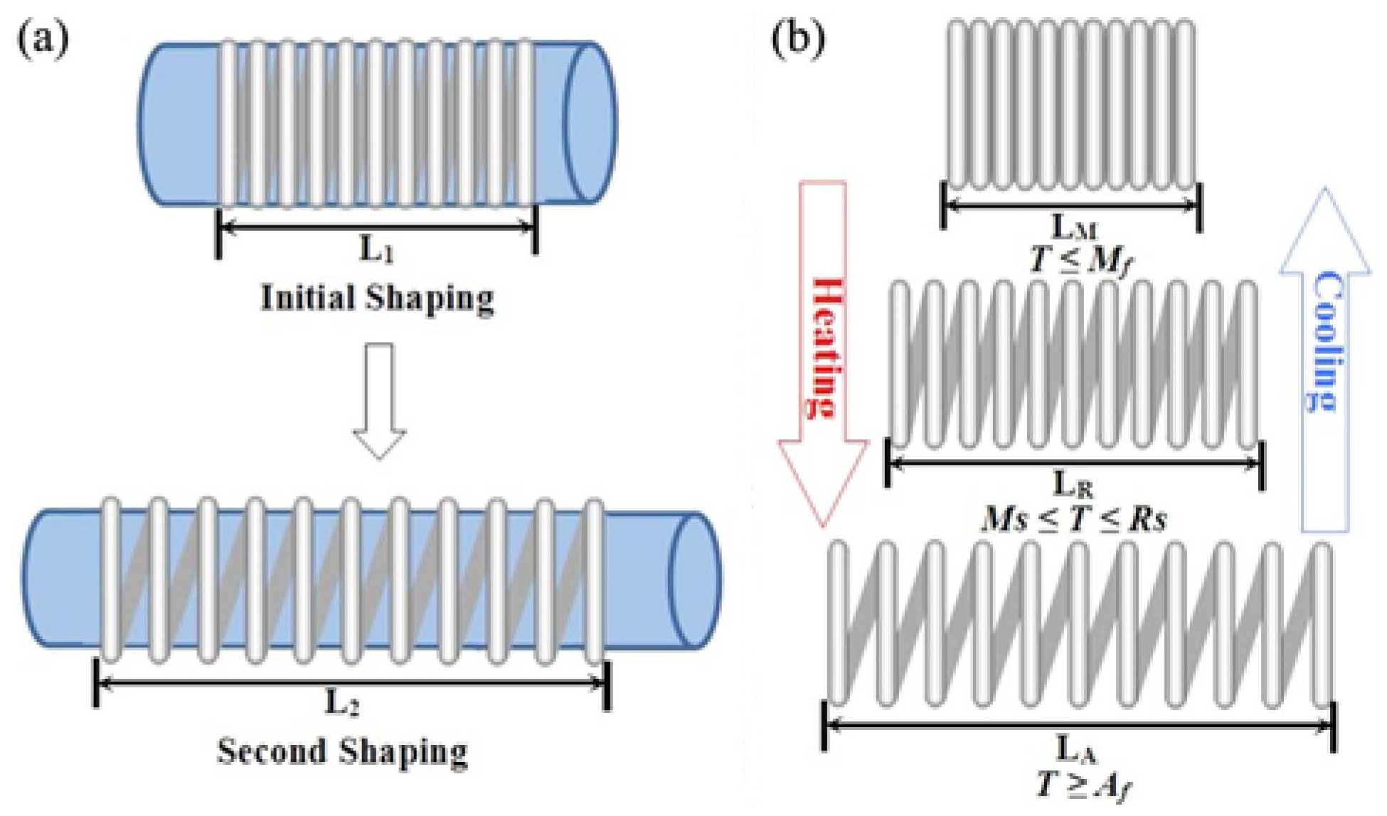
2. Thin-Film SMA

| References | Deposition Type | Atomic Composition | Mf (°C) | Ms (°C) | As (°C) | Af (°C) | Annealing Temperature (°C) | Annealing Duration (h) |
|---|---|---|---|---|---|---|---|---|
| Yang et al. [35] | Filtered arc | Ni51.0at%Ti49.0 | −9 | 49 | 4 | 71 | not available | not available |
| Kim et al. [44] | Co-sputtering | Ni49.4at%Ti50.6 | 57 | 63 | 86 | 100 | 700 | 10 |
| Chun et al. [49] | Sputtering | Ni49.5at%Ti50.5 | −17 | −3 | 22 | 35 | 500 | 2 |
| Sanjabi et al. [50] | Co-sputtering | Ni49.4at%Ti50.6 | 30 | 50 | 71 | 86 | 500 | 1 |
| Liu et al. [51] | Sputtering | Ni47.4at%Ti52.6 | 55 | 70 | 80 | 95 | 600 | not available |
| Mohanchandra et al. [52] | Sputtering | Ni47.5at%Ti52.5 | 45 | 66 | 81 | 98 | 500 | 2 |

3. Bulk Micromachined SMA

4. Actuation Methods and Applications
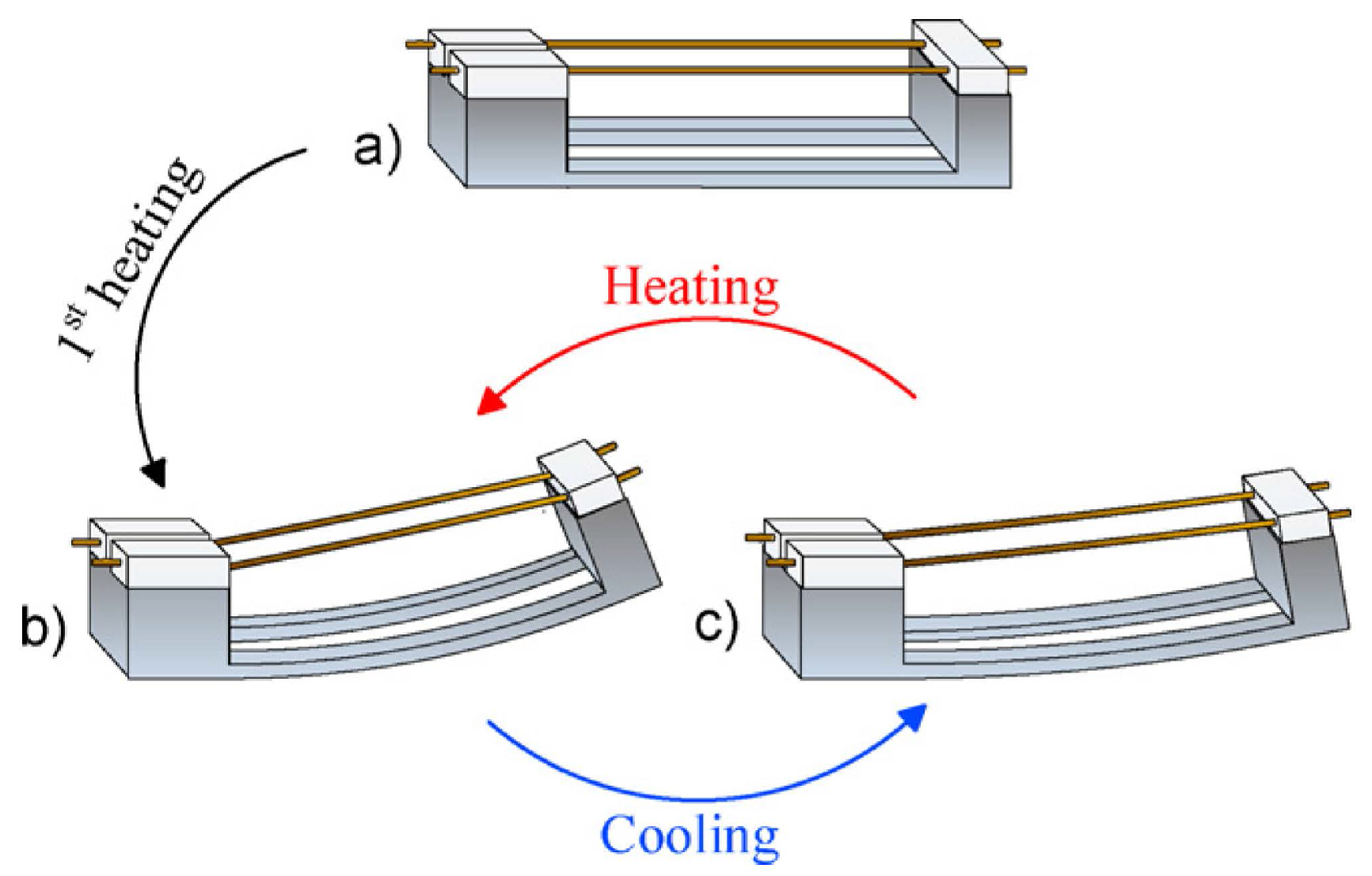
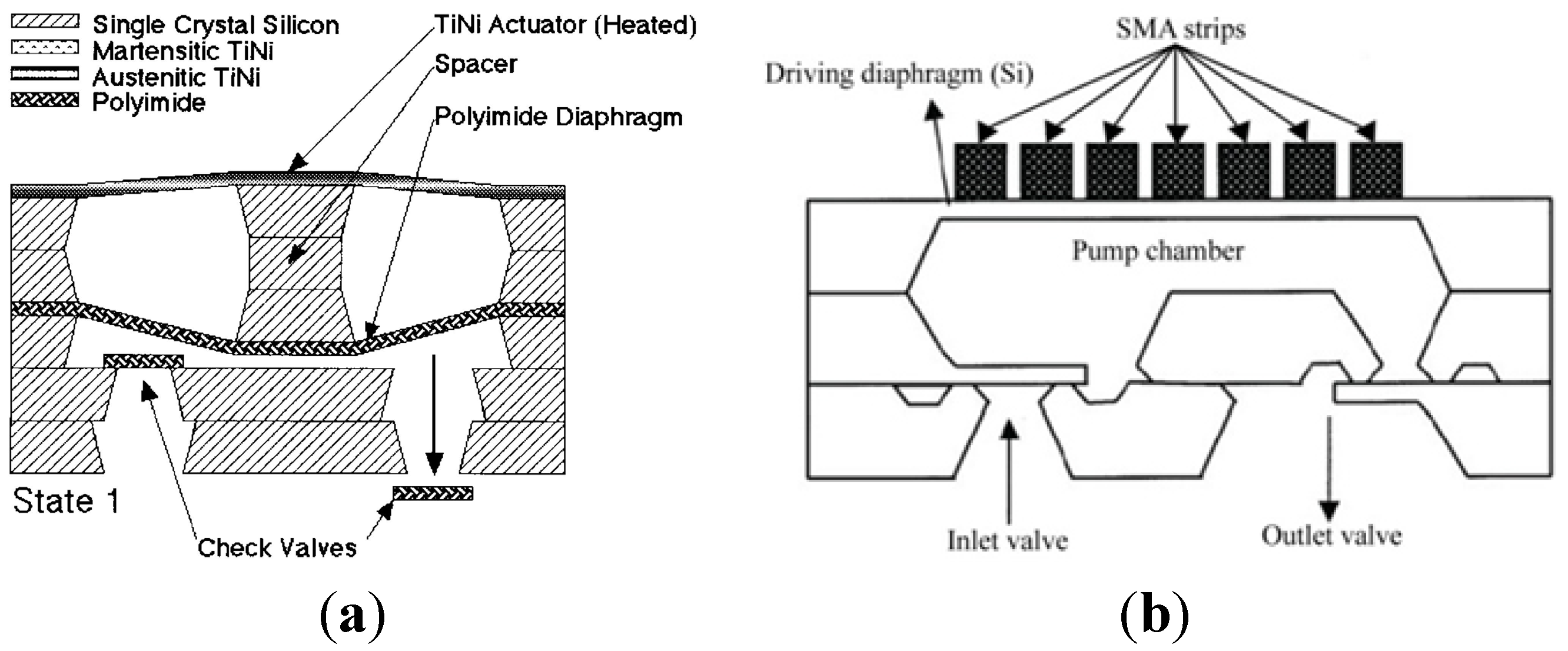
4.1. Thin-Film SMA Actuator


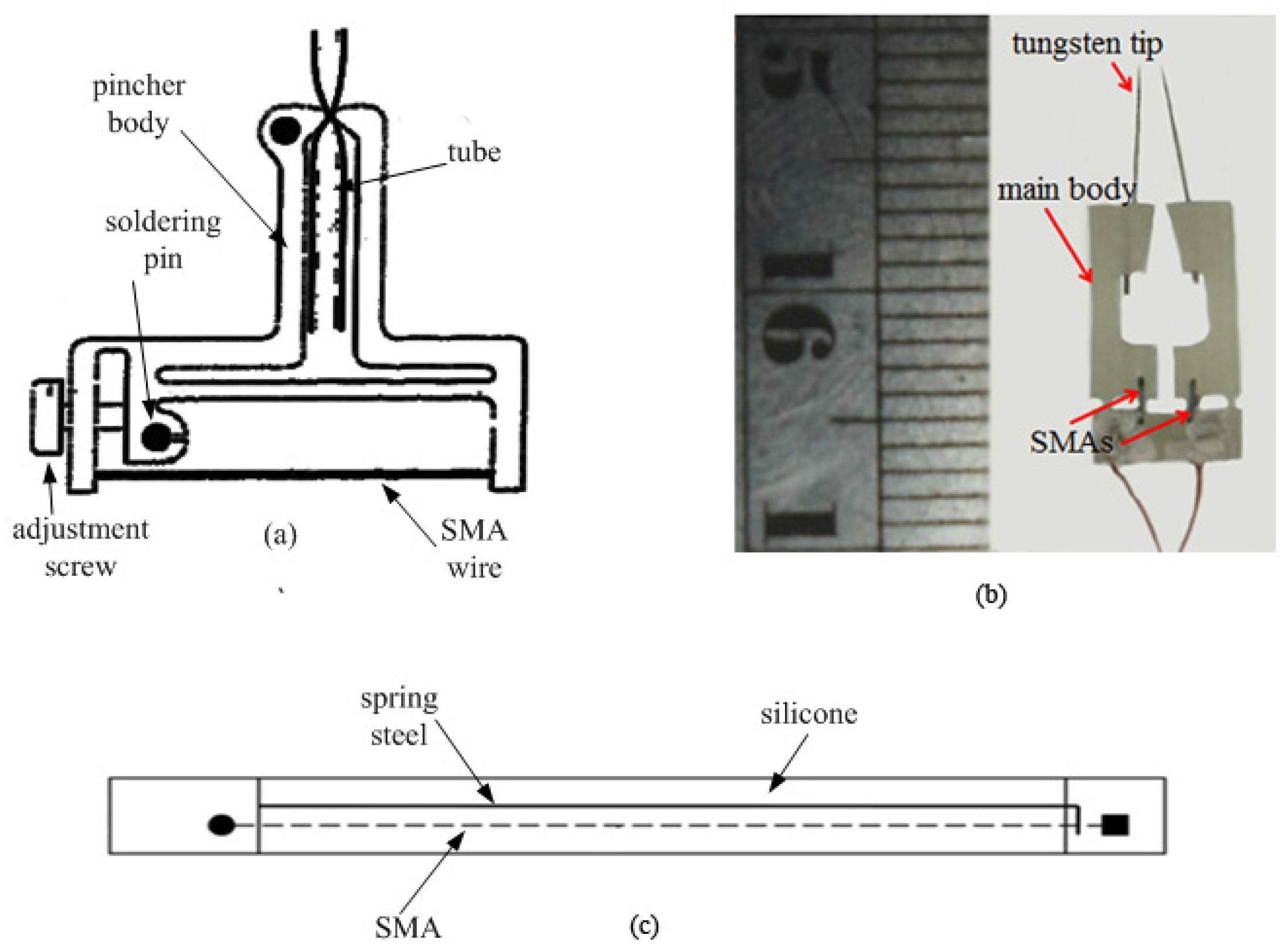
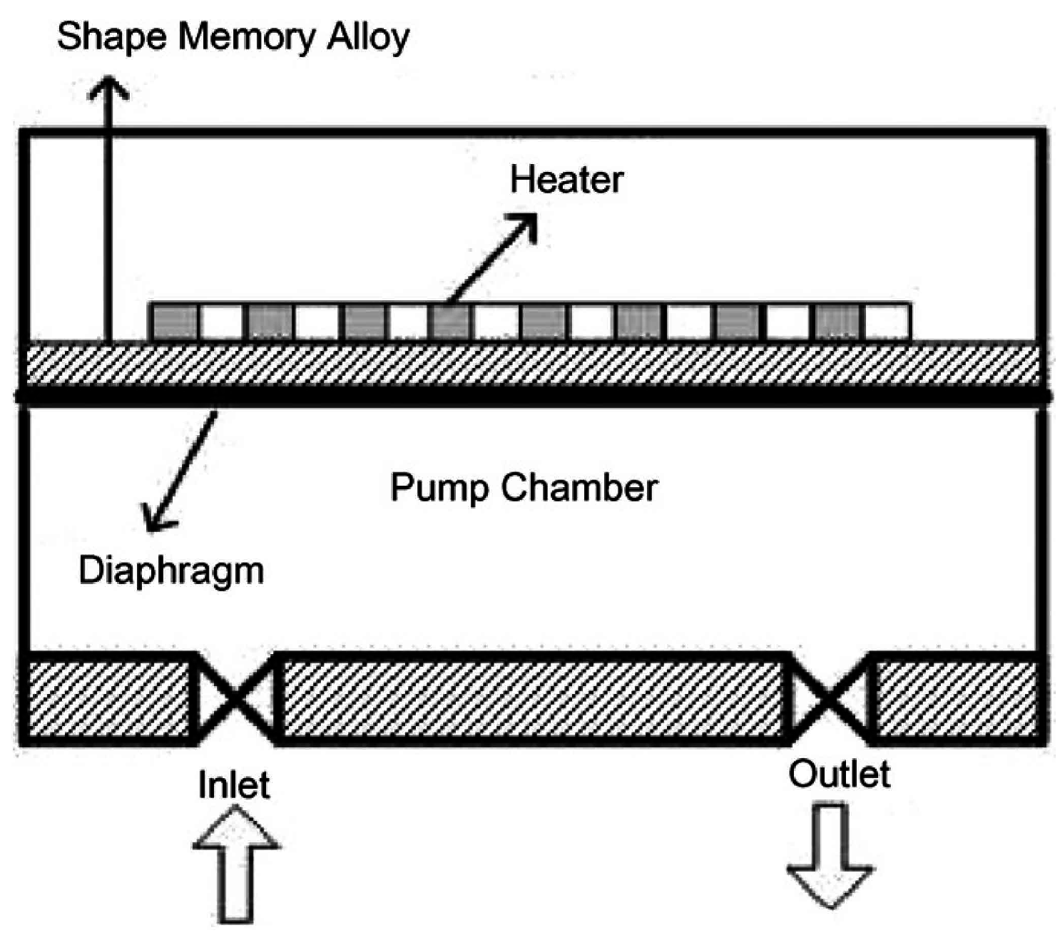
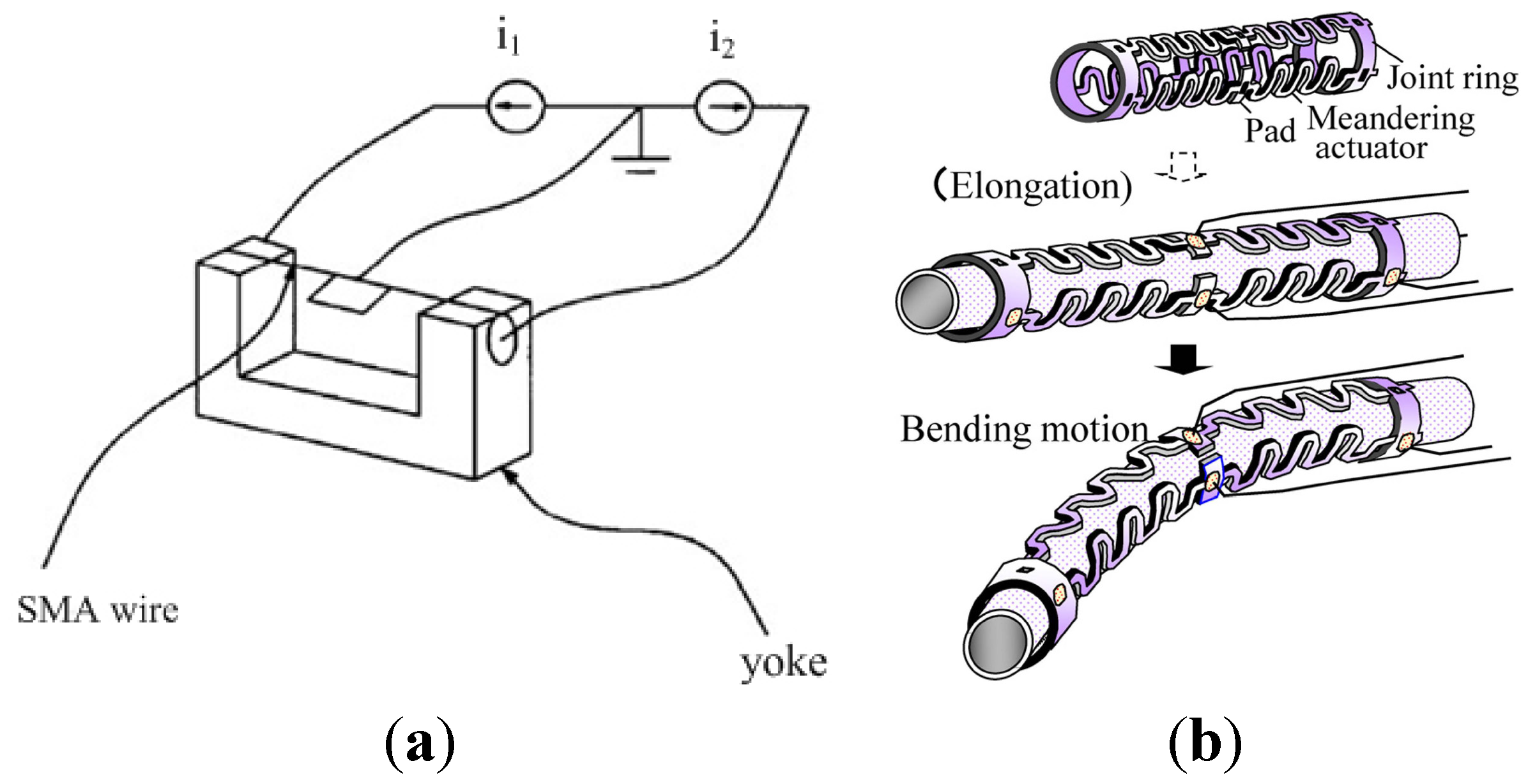
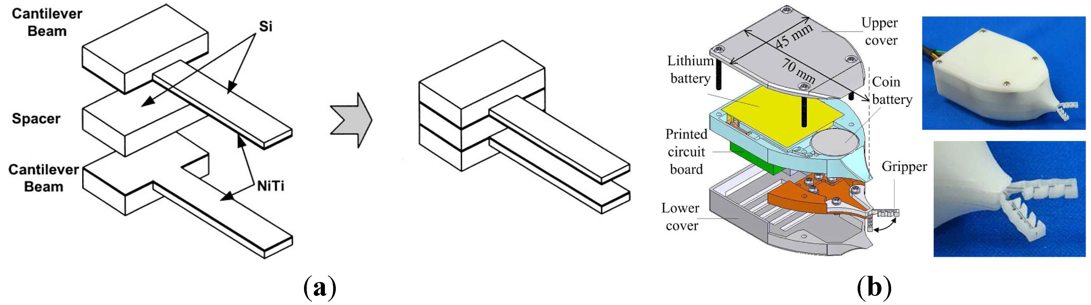
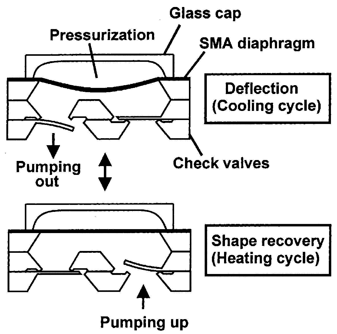
4.2. Bulk Micromachined-SMA Actuator


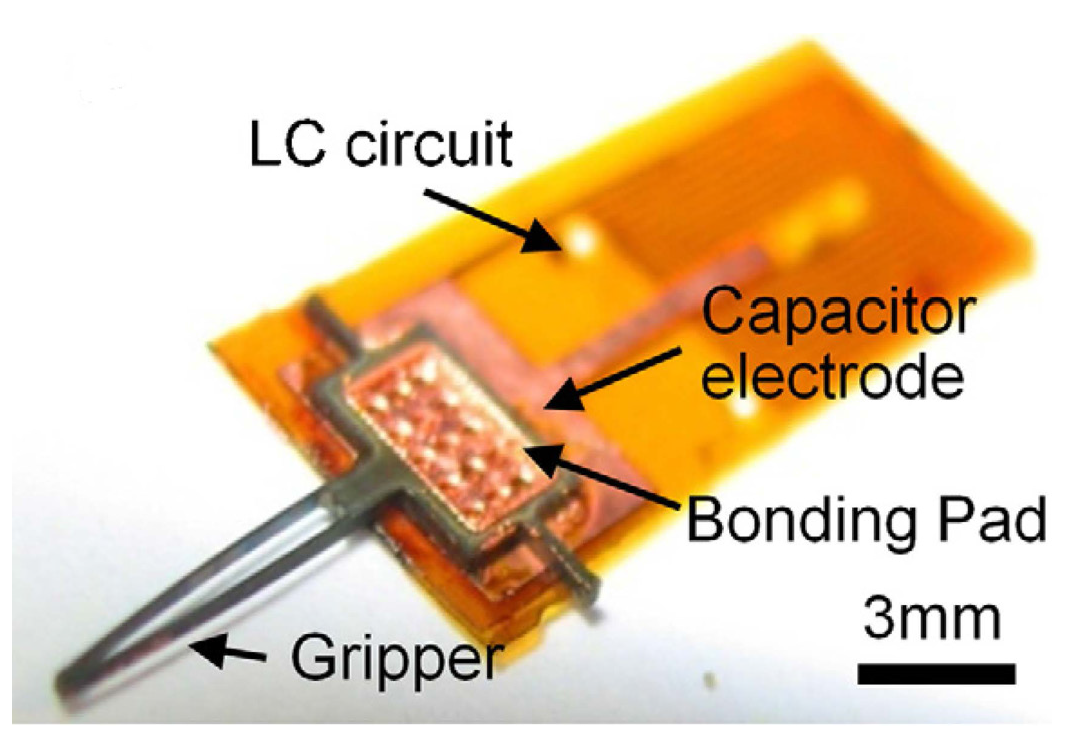
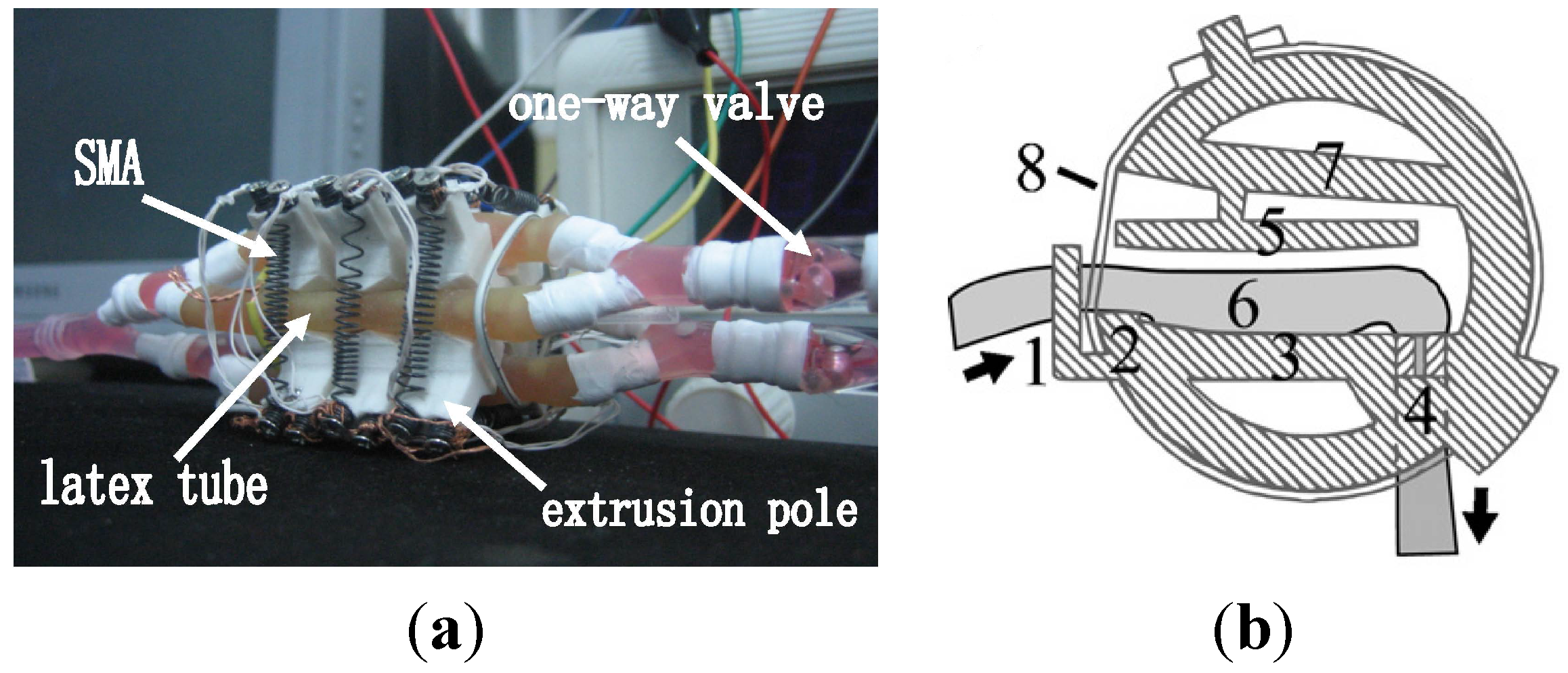
5. Micromechanism Device for Biomedical Applications


| References | Pump Type | Size | SMA Form | Bias Type | Highest Flowrate (μL/min) | Highest Frequency (Hz) | Diaphragm Displacement |
|---|---|---|---|---|---|---|---|
| [87] | Reciprocal | n/r | Thin-film | Polyimide | 6 at 0.8 Hz | 1.2 | n/r |
| [87] | Reciprocal | n/r | Thin-film | Antagonistic | 50 at 0.9 Hz | 1.1 | 80 μm |
| [88] | Reciprocal | 6 mm × 6 mm × 1.5 mm | Thin-film | NiTi/Si bimorph | 340 at 60 Hz | 100 | 5 μm |
| [89] | Reciprocal | 10 mm × 20 mm × 1.4 mm | Thin-film | Pressurization | 4.8 at 0.5 Hz | 0.5 | 95 μm |
| [125] | Reciprocal | 8 mm × 8 mm × 1.8 mm | Thin-film | NiTiCu/Si bimorph | 235 at 80 Hz | 100 | 6 μm |
| [130] | Reciprocal | 16 mm × 74 mm | Coil | TWSME | 700 at 2.0 Hz | 10 | 10 mm |
| [131] | Reciprocal | n/r | Coil | Antagonistic | n/r | n/r | n/r |
| [128] | Peristaltic | 45 mm × 30 mm × 30 mm | Coil | Antagonistic | 1000 at 0.6 Hz | 50 | 8 mm |
| [129] | Peristaltic | 1.3 cm3 | Wire | TWSME | 60 | n/r | n/r |
6. Conclusions
Acknowledgments
Conflicts of Interest
References
- Sun, L.; Huang, W.M.; Ding, Z.; Zhao, Y.; Wang, C.C.; Purnawali, H.; Tang, C. Stimulus-responsive shape memory materials: A review. Mater. Des. 2012, 33, 577–640. [Google Scholar] [CrossRef]
- Huang, W.M.; Ding, Z.; Wang, C.C.; Wei, J.; Zhao, Y.; Purnawali, H. Shape memory materials. Mater. Today 2010, 13, 54–61. [Google Scholar] [CrossRef]
- Otsuka, K.; Kakeshita, T. Science and technology of shape-memory alloys: New developments. MRS Bull. 2002, 27, 91–98. [Google Scholar] [CrossRef]
- Kudva, J.N. Overview of the DARPA Smart Wing Project. J. Intell. Mater. Syst. Struct. 2004, 15, 261–267. [Google Scholar] [CrossRef]
- Dunne, J.; Pitt, D.; White, E.; Garcia, E. Ground demonstration of the Smart Inlet. In Proceedings of the 41st Structures, Structural Dynamics, and Materials Conference, Atlanta, GA, USA, 3–6 April 2000.
- Petrini, L.; Migliavacca, F. Biomedical Applications of Shape Memory Alloys. J. Metall. 2011, 2011, 1–15. [Google Scholar] [CrossRef]
- Small, W., IV; Wilson, T.S.; Buckley, P.R.; Benett, W.J.; Loge, J.M.; Hartman, J.; Maitland, D.J. Prototype fabrication and preliminary in vitro testing of a shape memory endovascular thrombectomy device. IEEE Trans. Biomed. Eng. 2007, 54, 1657–1666. [Google Scholar] [CrossRef] [PubMed]
- Haga, Y.; Mizushima, M.; Matsunaga, T.; Esashi, M. Medical and welfare applications of shape memory alloy microcoil actuators. Smart Mater. Struct. 2005, 14, S266–S272. [Google Scholar] [CrossRef]
- Bossi, S.; Kammer, S.; Dörge, T.; Menciassi, A.; Hoffmann, K.P.; Micera, S. An implantable microactuated intrafascicular electrode for peripheral nerves. IEEE Trans. Biomed. Eng. 2009, 56, 2701–2706. [Google Scholar] [CrossRef] [PubMed]
- Murad, S.; Murad, J.; Khan, H. A smarter SMA technology for the realization of drug delivering endoscopic capsule. Rawal Med. J. 2013, 38, 66–74. [Google Scholar]
- Miyazaki, S.; Kim, H.Y.; Hosoda, H. Development and characterization of Ni-free Ti-base shape memory and superelastic alloys. Mater. Sci. Eng. A 2006, 438–440, 18–24. [Google Scholar] [CrossRef]
- McMahon, R.E.; Ma, J.; Verkhoturov, S.V.; Munoz-Pinto, D.; Karaman, I.; Rubitschek, F.; Maier, H.J.; Hahn, M.S. A comparative study of the cytotoxicity and corrosion resistance of nickel-titanium and titanium-niobium shape memory alloys. Acta Biomater. 2012, 8, 2863–2870. [Google Scholar] [CrossRef] [PubMed]
- Farooq, M.U.; Khalid, F.A.; Zaigham, H.; Abidi, I.H. Superelastic behaviour of Ti-Nb-Al ternary shape memory alloys for biomedical applications. Mater. Lett. 2014, 121, 58–61. [Google Scholar] [CrossRef]
- Lai, M.; Gao, Y.; Yuan, B.; Zhu, M. Effect of Pore Structure Regulation on the Properties of Porous TiNbZr Shape Memory Alloys for Biomedical Application. J. Mater. Eng. Perform. 2015, 24, 136–142. [Google Scholar] [CrossRef]
- Ijaz, M.F.; Kim, H.Y.; Hosoda, H.; Miyazaki, S. Superelastic properties of biomedical (Ti-Zr)-Mo-Sn alloys. Mater. Sci. Eng. C 2015, 48, 11–20. [Google Scholar] [CrossRef] [PubMed]
- Surbled, P.; Clerc, C.; le Pioufle, B.; Ataka, M.; Fujita, H. Effect of the composition and thermal annealing on the transformation temperatures of sputtered TiNi shape memory alloy thin films. Thin Solid Films 2001, 401, 52–59. [Google Scholar] [CrossRef]
- Sandström, N.; Braun, S.; Stemme, G.; van der Wijngaart, W.; Royal, K.T.H. Full Wafer Integration of Shape Memory Alloy Microactuators Using Adhesive Bonding. In Proceedings of the Transducer 2009, International Solid-State Sensors, Actuators and Microsystems Conference, Denver, CO, USA, 21–25 June 2009; pp. 845–848.
- Biffi, C.A.; Nespoli, A.; Previtali, B.; Villa, E.; Tuissi, A. Functional Response of NiTi Elements for Smart Micro-actuation Applications. J. Mater. Eng. Perform. 2014, 23, 2351–2356. [Google Scholar] [CrossRef]
- Mohamed Ali, M.S.; Takahata, K. Frequency-controlled wireless shape-memory-alloy microactuators integrated using an electroplating bonding process. Sens. Actuators A Phys. 2010, 163, 363–372. [Google Scholar] [CrossRef]
- Wang, J. Shape memory effect of TiNi-based springs trained by constraint annealing. Met. Mater. Int. 2013, 19, 295–301. [Google Scholar] [CrossRef]
- Walker, J.A.; Gabriel, K.J.; Mehregany, M. Thin-film processing of TiNi shape memory alloy. Sens. Actuators A Phys. 1990, 21, 243–246. [Google Scholar] [CrossRef]
- Roch, I.; Bidaud, P.; Collard, D.; Buchaillot, L. Fabrication and characterization of an SU-8 gripper actuated by a SMA thin film. J. Micromech. Microeng. 2003, 13, 330. [Google Scholar] [CrossRef]
- Gill, J.J.; Ho, K.; Carman, G.P. Three-dimensional thin-film shape memory alloy microactuator with two-way effect. J. Microelectromech. Syst. 2002, 11, 68–77. [Google Scholar] [CrossRef]
- Zhang, H.; Qiu, C. Characteristic of TiNi(Cu) shape memory thin film based on micropump. In Proceedings of the 2nd International Conference on Smart Materials and Nanotechnology in Engineering, Weihai, China, 8–11 July 2009.
- Kuribayashi, K. Micro SMA actuator and motion control. In Proceedings of the 2000 International Symphosium on Micromechatronics and Human Science, Nagoya, Japan, 22–25 October 2000; pp. 35–42.
- Tomozawa, M.; Kim, H.Y.; Miyazaki, S. Microactuators Using R-phase Transformation of Sputter-deposited Ti-47.3Ni Shape Memory Alloy Thin Films. J. Intell. Mater. Syst. Struct. 2006, 17, 1049–1058. [Google Scholar] [CrossRef]
- Bhattacharya, R.S.; Rai, A.K.; Pronko, P.P. Corrosion behavior of amorphous TiNi films fabricated by ion beam mixing. Mater. Lett. 1984, 2, 483–486. [Google Scholar] [CrossRef]
- Makino, E.; Uenoyama, M.; Shibata, T. Flash evaporation of TiNi shape memory thin film for microactuators. Sens. Actuators A Phys. 1998, 71, 187–192. [Google Scholar] [CrossRef]
- Adams, T.M.; Kirkpatrick, S.R.; Wang, Z.; Siahmakoun, A. NiTi shape memory alloy thin films deposited by co-evaporation. Mater. Lett. 2005, 59, 1161–1164. [Google Scholar] [CrossRef]
- Chen, X.; Lu, Y.; Ren, Z.; Zhu, S. The fabrication of TiNi thin films by pulsed-laser deposition. Proc. SPIE 2002, 4426, 225–228. [Google Scholar]
- Cha, J.O.; Nam, T.H.; Alghusun, M.; Ahn, J.S. Composition and crystalline properties of TiNi thin films prepared by pulsed laser deposition under vacuum and in ambient Ar gas. Nanoscale Res. Lett. 2012, 7, 1–15. [Google Scholar] [CrossRef] [PubMed]
- Ahn, J.S.; Cha, J.O.; Shin, C.H.; Yeo, S.J.; Im, H.J.; Sakai, J.; Lee, K.B.; Kim, H.M.; Nam, T.H. Effect of ambient Ar gas on the composition control and crystalline properties of TiNi thin films fabricated by using pulsed laser deposition. J. Korean Phys. Soc. 2007, 50, 1750–1754. [Google Scholar] [CrossRef]
- Chen, X.Y.; Lu, Y.F.; Ren, Z.M.; Zhu, S. Fabrication of TiNi shape memory alloy thin films by pulsed-laser deposition. J. Mater. Res. 2002, 17, 279–283. [Google Scholar] [CrossRef]
- Ciabattari, F.; Fuso, F.; Arimondo, E. Pulsed laser deposition of NiTi shape memory effect thin films. Appl. Phys. A Mater. Sci. Process. 1998, 64, 623–626. [Google Scholar] [CrossRef]
- Yang, L.M.; Tieu, A.K.; Dunne, D.P.; Huang, S.W.; Li, H.J.; Wexler, D.; Jiang, Z.Y. Cavitation erosion resistance of NiTi thin films produced by Filtered Arc Deposition. Wear 2009, 267, 233–243. [Google Scholar] [CrossRef]
- Barborini, E.; Piseri, P.; Mutti, S.; Milani, P.; Biasioli, F.; Iannotta, S.; Gialanella, S. Synthesis of nanocrystalline TiNi thin films by cluster beam deposition. Nanostruct. Mater. 1998, 10, 1023–1031. [Google Scholar] [CrossRef]
- He, J.L.; Won, K.W.; Chang, J.T. TiNi thin films prepared by cathodic arc plasma ion plating. Thin Solid Films 2000, 359, 46–54. [Google Scholar] [CrossRef]
- Ishida, A. Progress in thin-film shape-memory-alloy actuators. In Proceedings of the 17th International Conference on Solid-State Sensors, Actuators and Microsystems (TRANSDUCERS and EUROSENSORS XXVII), Barcelona, Spain, 16–20 June 2013; pp. 1573–1578.
- Reichelt, K.; Jiang, X. The preparation of thin films by physical vapour deposition methods. Thin Solid Films 1990, 191, 91–126. [Google Scholar] [CrossRef]
- Boyd, A.R.; O’Kane, C.; Meenan, B.J. Control of calcium phosphate thin film stoichiometry using multi-target sputter deposition. Surf. Coat. Technol. 2013, 233, 131–139. [Google Scholar] [CrossRef]
- Schell, N.; Martins, R.M.S.; Braz Fernandes, F.M. Real-time and in-situ structural design of functional NiTi SMA thin films. Appl. Phys. A Mater. Sci. Process. 2005, 81, 1441–1445. [Google Scholar] [CrossRef]
- Kabla, M.; Seiner, H.; Musilova, M.; Landa, M.; Shilo, D. The relationships between sputter deposition conditions, grain size, and phase transformation temperatures in NiTi thin films. Acta Mater. 2014, 70, 79–91. [Google Scholar] [CrossRef]
- Ho, K.K.; Carman, G.P. Sputter deposition of NiTi thin film shape memory alloy using a heated target. Thin Solid Films 2000, 370, 18–29. [Google Scholar] [CrossRef]
- Kim, S.-W.; Jeon, Y.M.; Park, C.H.; Kim, J.H.; Kim, D.-H.; Yeom, J.-T. Martensitic phase transformation of TiNi thin films fabricated by co-sputtering deposition. J. Alloys Compd. 2013, 580, 5–9. [Google Scholar] [CrossRef]
- Huang, X.; Liu, Y. Surface morphology of sputtered NiTi-based shape memory alloy thin films. Surf. Coat. Technol. 2005, 190, 400–405. [Google Scholar] [CrossRef]
- Huang, X.; Liu, Y. Some factors affecting the properties of sputter deposited NiTi-based shape memory alloy thin films. Proc. SPIE 2002, 4934, 210–218. [Google Scholar]
- Tang, W.; Sundman, B.; Sandström, R.; Qiu, C. New modelling of the B2 phase and its associated martensitic transformation in the Ti-Ni system. Acta Mater. 1999, 47, 3457–3468. [Google Scholar] [CrossRef]
- Bendahan, M.; Seguin, J.-L.; Canet, P.; Carchano, H. NiTi shape memory alloy thin films: Composition control using optical emission spectroscopy. Thin Solid Films 1996, 283, 61–66. [Google Scholar] [CrossRef]
- Chun, Y.J.; Levi, D.S.; Mohanchandra, K.P.; Fishbein, M.C.; Carman, G.P. Novel micro-patterning processes for thin film NiTi vascular devices. Smart Mater. Struct. 2010, 19, 105021. [Google Scholar] [CrossRef]
- Sanjabi, S.; Naderi, M.; Zare Bidaki, H.; Sadrnezhaad, S.K.; Bidaki, H.Z. Characterization of sputtered NiTi shape memory alloy thin films. Sci. Iran. 2009, 16, 248–252. [Google Scholar]
- Liu, Y.S.; Xu, D.; Jiang, B.H.; Yuan, Z.Y.; van Houtte, P. The effect of crystallizing procedure on microstructure and characteristics of sputter-deposited TiNi shape memory thin films. J. Micromech. Microeng. 2005, 15, 575–579. [Google Scholar] [CrossRef]
- Mohanchandra, K.P.; Ho, K.K.; Carman, G.P. Compositional uniformity in sputter-deposited NiTi shape memory alloy thin films. Mater. Lett. 2008, 62, 3481–3483. [Google Scholar] [CrossRef]
- Fu, Y.; Du, H.; Huang, W.; Zhang, S.; Hu, M. TiNi-based thin films in MEMS applications: A review. Sens. Actuators A Phys. 2004, 112, 395–408. [Google Scholar] [CrossRef]
- Cole, D.; Bruck, H.; Roytburd, A. Nanomechanical characterization of diffusion-modified graded NiTi films. In Proceedings of the 11th International Congress and Exhibition on Experimental and Applied Mechanics, Orlando, FL, USA, 2–5 June 2008; pp. 1722–1728.
- Martins, R.M.S.; Schell, N.; Reuther, H.; Pereira, L.; Mahesh, K.K.; Silva, R.J.C.; Fernandes, F.M.B. Texture development, microstructure and phase transformation characteristics of sputtered Ni-Ti Shape Memory Alloy films grown on TiN<111>. Thin Solid Films 2010, 519, 122–128. [Google Scholar] [CrossRef]
- Martins, R.M.S.; Schell, N.; Mahesh, K.K.; Silva, R.J.C.; Fernandes, F.M.B. X-ray diffraction studies during magnetron co-sputtering of Ni-Ti shape memory alloy films. Ciênc. Tecnol. Mater. 2012, 24, 161–169. [Google Scholar]
- Sato, M.; Ishida, A.; Miyazaki, S. Two-Way shape memory effect of sputter-deposited thin films of Ti 51.3 at.% Ni. Thin Solid Films 1998, 315, 305–309. [Google Scholar] [CrossRef]
- He, Q.; Hong, M.H.; Huang, W.M.; Chong, T.C.; Fu, Y.Q.; Du, H.J. CO2 laser annealing of sputtering deposited NiTi shape memory thin films. J. Micromech. Microeng. 2004, 14, 950–956. [Google Scholar] [CrossRef]
- Sadrnezhaad, S.K.; Rezvani, E.; Sanjabi, S.; Ziaei Moayed, A.A. Pulsed-laser annealing of NiTi shape memory alloy thin film. J. Mater. Sci. Technol. 2009, 25, 135–140. [Google Scholar]
- Bellouard, Y.; Lehnert, T.; Bidaux, J.-E.; Sidler, T.; Clavel, R.; Gotthardt, R. Local annealing of complex mechanical devices: A new approach for developing monolithic micro-devices. Mater. Sci. Eng. A 1999, 273–275, 795–798. [Google Scholar] [CrossRef]
- Frenzel, J.; Zhang, Z.; Somsen, C.; Neuking, K.; Eggeler, G. Influence of carbon on martensitic phase transformations in NiTi shape memory alloys. Acta Mater. 2007, 55, 1331–1341. [Google Scholar] [CrossRef]
- Frenzel, J.; Zhang, Z.; Neuking, K.; Eggeler, G. High quality vacuum induction melting of small quantities of NiTi shape memory alloys in graphite crucibles. J. Alloys Compd. 2004, 385, 214–223. [Google Scholar] [CrossRef]
- Nayan, N.; Govind; Saikrishna, C.N.; Ramaiah, K.V.; Bhaumik, S.K.; Nair, K.S.; Mittal, M.C. Vacuum induction melting of NiTi shape memory alloys in graphite crucible. Mater. Sci. Eng. A 2007, 465, 44–48. [Google Scholar] [CrossRef]
- Kabiri, Y.; Kermanpur, A.; Foroozmehr, A. Comparative study on microstructure and homogeneity of NiTi shape memory alloy produced by copper boat induction melting and conventional vacuum arc melting. Vacuum 2012, 86, 1073–1077. [Google Scholar] [CrossRef]
- Frenzel, J.; George, E.P.; Dlouhy, A.; Somsen, C.; Wagner, M.F.-X.; Eggeler, G. Influence of Ni on martensitic phase transformations in NiTi shape memory alloys. Acta Mater. 2010, 58, 3444–3458. [Google Scholar] [CrossRef]
- Lin, H.C.; Wu, S.K. Effects of hot rolling on the martensitic transformation of an equiatomic TiNi alloy. Mater. Sci. Eng. A 1992, 158, 87–91. [Google Scholar] [CrossRef]
- Shahmir, H.; Nili-Ahmadabadi, M.; Naghdi, F. Superelastic behavior of aged and thermomechanical treated NiTi alloy at Af +10 °C. Mater. Des. 2011, 32, 365–370. [Google Scholar] [CrossRef]
- Otubo, J.; Rigo, O.D.; Neto, C.M.; Mei, P.R. The effects of vacuum induction melting and electron beam melting techniques on the purity of NiTi shape memory alloys. Mater. Sci. Eng. A 2006, 438–440, 679–682. [Google Scholar] [CrossRef]
- Huang, W.; Goh, H.B. On the long-term stability of two-way shape memory alloy trained by reheat treatment. J. Mater. Sci. Lett. 2001, 20, 1795–1797. [Google Scholar] [CrossRef]
- Huang, W.M.; Goh, H.B.; Li, C. Effects of reheat treatment conditions on two-way shape memory. J. Mater. Sci. Lett. 2002, 21, 991–993. [Google Scholar] [CrossRef]
- Huang, W.; Toh, W. Training two-way shape memory alloy by reheat treatment. J. Mater. Sci. Lett. 2000, 19, 1549–1550. [Google Scholar] [CrossRef]
- Chang, C.-Y.; Vokoun, D.; Hu, C.-T. Two-way shape memory effect of NiTi alloy induced by constraint aging treatment at room temperature. Metall. Mater. Trans. A Phys. Metall. Mater. Sci. 2001, 32, 1629–1634. [Google Scholar] [CrossRef]
- Wada, K.; Liu, Y. On the two-way shape memory behavior in NiTi alloy-An experimental analysis. Acta Mater. 2008, 56, 3266–3277. [Google Scholar] [CrossRef]
- Costanza, G.; Tata, M.E.; Calisti, C. Nitinol one-way shape memory springs: Thermomechanical characterization and actuator design. Sens. Actuators A Phys. 2010, 157, 113–117. [Google Scholar] [CrossRef]
- Lahoz, R.; Puértolas, J.A. Training and two-way shape memory in NiTi alloys: Influence on thermal parameters. J. Alloys Compd. 2004, 381, 130–136. [Google Scholar] [CrossRef]
- Kato, T.; Tokuda, M.; Inaba, T.; Yamazaki, M. Experimental research on two-way shape memory effect of TiNi shape memory alloy. Key Eng. Mater. 2004, 274–276, 1095–1100. [Google Scholar] [CrossRef]
- Wada, K.; Liu, Y. Thermomechanical training and the shape recovery characteristics of NiTi alloys. Mater. Sci. Eng. A 2008, 481–482, 166–169. [Google Scholar] [CrossRef]
- Kim, H.-C.; Yoo, Y.-I.; Lee, J.-J. Development of a NiTi actuator using a two-way shape memory effect induced by compressive loading cycles. Sens. Actuators A Phys. 2008, 148, 437–442. [Google Scholar] [CrossRef]
- Yoo, Y.I.; Lee, J.J. Two-way shape memory effect of NiTi under compressive loading cycles. Phys. Procedia 2011, 22, 449–454. [Google Scholar] [CrossRef]
- Yoo, Y.I.; Jeong, J.W.; Lee, J.J.; Lee, C.H. Effect of heat treatment on the two-way recovery stress of tube-shaped NiTi. J. Intell. Mater. Syst. Struct. 2012, 23, 1161–1168. [Google Scholar] [CrossRef]
- Behl, M.; Lendlein, A. Triple-Shape polymers. J. Mater. Chem. 2010, 20, 3335–3345. [Google Scholar] [CrossRef]
- Wei, M.; Zhan, M.; Yu, D.; Xie, H.; He, M.; Yang, K.; Wang, Y. Novel poly(tetramethylene ether)glycol and poly(ε-caprolactone) based dynamic network via quadruple hydrogen bonding with triple-shape effect and self-healing capacity. ACS Appl. Mater. Interfaces 2015, 7, 2585–2596. [Google Scholar] [CrossRef] [PubMed]
- Nejad, H.B.; Baker, R.M.; Mather, P.T. Preparation and characterization of triple shape memory composite foams. Soft Matter 2014, 10, 8066–8074. [Google Scholar] [CrossRef] [PubMed]
- Chatani, S.; Wang, C.; Podgórski, M.; Bowman, C.N. Triple shape memory materials incorporating two distinct polymer networks formed by selective thiol-Michael addition reactions. Macromolecules 2014, 47, 4949–4954. [Google Scholar] [CrossRef]
- Tang, C.; Huang, W.M.; Wang, C.C.; Purnawali, H. The triple-shape memory effect in NiTi shape memory alloys. Smart Mater. Struct. 2012, 21, 085022. [Google Scholar] [CrossRef]
- Nisar, A.; Afzulpurkar, N.; Mahaisavariya, B.; Tuantranont, A. MEMS-Based micropumps in drug delivery and biomedical applications. Sens. Actuators B Chem. 2008, 130, 917–942. [Google Scholar] [CrossRef]
- Benard, W.L.; Kahn, H.; Heuer, A.H.; Huff, M.A. Thin-film shape-memory alloy actuated micropumps. J. Microelectromech. Syst. 1998, 7, 245–251. [Google Scholar] [CrossRef]
- Xu, D.; Wang, L.; Ding, G.; Zhou, Y.; Yu, A.; Cai, B. Characteristics and fabrication of NiTi/Si diaphragm micropump. Sens. Actuators A Phys. 2001, 93, 87–92. [Google Scholar] [CrossRef]
- Makino, E.; Mitsuya, T.; Shibata, T. Fabrication of TiNi shape memory micropump. Sens. Actuators A Phys. 2001, 88, 256–262. [Google Scholar] [CrossRef]
- Shin, D.D.; Mohanchandra, K.P.; Carman, G.P. Development of hydraulic linear actuator using thin film SMA. Sens. Actuators A Phys. 2005, 119, 151–156. [Google Scholar] [CrossRef]
- Wongweerayoot, E.; Srituravanich, W.; Pimpin, A. Fabrication and Characterization of Nitinol-Copper Shape Memory Alloy Bimorph Actuators. J. Mater. Eng. Perform. 2014, 24, 635–643. [Google Scholar] [CrossRef]
- Braun, S.; Sandstrom, N.; Stemme, G.; van der Wijngaart, W. Wafer-scale manufacturing of bulk shape-memory-alloy microactuators based on adhesive bonding of titanium-nickel sheets to structured silicon wafers. J. Microelectromech. Syst. 2009, 18, 1309–1317. [Google Scholar] [CrossRef]
- Mohamed Ali, M.S.; Takahata, K. Wireless microfluidic control with integrated shape-memory-alloy actuators operated by field frequency modulation. J. Micromech. Microeng. 2011, 21, 075005. [Google Scholar] [CrossRef]
- Dahmardeh, M.; Mohamed Ali, M.S.; Saleh, T.; Hian, T.M.; Moghaddam, M.V.; Nojeh, A.; Takahata, K. High-power MEMS switch enabled by carbon-nanotube contact and shape-memory-alloy actuator. Phys. Status Solidi 2013, 210, 631–638. [Google Scholar] [CrossRef]
- Li, Y.F.; Mi, X.J.; Yin, X.Q.; Xie, H.F. Constrained recovery properties of NiTi shape memory alloy wire during thermal cycling. J. Alloys Compd. 2014, 588, 525–529. [Google Scholar] [CrossRef]
- Pan, G.H.; Huang, W.M. A note on constrained shape memory alloys upon thermal cycling. J. Mater. Sci. 2006, 41, 7964–7968. [Google Scholar] [CrossRef]
- Mohamed Ali, M.S.; Ali, M.; Bycraft, B.; Bsoul, A.; Takahata, K. Radio-controlled microactuator based on shape-memory-alloy spiral-coil inductor. J. Microelectromech. Syst. 2013, 22, 331–338. [Google Scholar] [CrossRef]
- Reynaerts, D.; van Brussel, H. Design aspects of shape memory actuators. Mechatronics 1998, 8, 635–656. [Google Scholar] [CrossRef]
- Yoo, Y.I.; Lee, J.J.; Lee, C.H.; Lim, J.H. An experimental study of the two-way shape memory effect in a NiTi tubular actuator. Smart Mater. Struct. 2010, 19, 125002. [Google Scholar] [CrossRef]
- Reynaerts, D.; Peirs, J.; van Brussel, H. An implantable drug-delivery system based on shape memory alloy micro-actuation. Sens. Actuators A Phys. 1997, 61, 455–462. [Google Scholar] [CrossRef]
- Zhao, H.; Chang, M.; Liu, X.; Gabayno, J.L.; Chen, H.T. Design and implementation of shape memory alloy-actuated nanotweezers for nanoassembly. J. Micromech. Microeng. 2014, 24, 095012. [Google Scholar] [CrossRef]
- Villanueve, A.; Smith, C.; Priya, S. A biomimetic robotic jellyfish (Robojelly) actuated by shape memory alloy composite actuators. Bioinspir. Biomim. 2011, 6, 036004. [Google Scholar] [CrossRef] [PubMed]
- Clausi, D.; Gradin, H.; Braun, S.; Peirs, J.; Stemme, G.; Reynaerts, D.; van der Wijngaart, W. Robust actuation of silicon MEMS using SMA wires integrated at wafer-level by nickel electroplating. Sens. Actuators A Phys. 2013, 189, 108–116. [Google Scholar] [CrossRef]
- Gabriel, K.J.; Trimmer, W.S.N.; Walker, J.A. A micro rotary actuator using shape memory alloys. Sens. Actuators 1988, 15, 95–102. [Google Scholar] [CrossRef]
- Mineta, T.; Deguchi, T.; Makino, E.; Kawashima, T.; Shibata, T. Fabrication of cylindrical micro actuator by etching of TiNiCu shape memory alloy tube. Sens. Actuators A Phys. 2011, 165, 392–398. [Google Scholar] [CrossRef]
- Mineta, T.; Kudoh, S.; Makino, E.; Kawashima, T.; Shibata, T. Accurate and simple assembly process of shape memory alloy tubular micro manipulator with a bias mechanism. Microelectron. Eng. 2011, 88, 2683–2686. [Google Scholar] [CrossRef]
- Chan, K.C.; Godman, M.J.; Walsh, K.; Wilson, N.; Redington, A.; Gibbs, J.L. Transcatheter closure of atrial septal defect and interatrial communications with a new self expanding nitinol double disc device (Amplatzer septal occluder): Multicentre UK experience. Heart 1999, 82, 300–306. [Google Scholar] [CrossRef] [PubMed]
- Kaufman, J.A.; Geller, S.C.; Brewster, D.C.; Fan, C.-M.; Cambria, R.P.; Lamuraglia, G.M.; Gertler, J.P.; Abbott, W.M.; Waltman, A.C. Endovascular repair of abdominal aortic aneurysms: Current status and future directions. Am. J. Roentgenol. 2000, 175, 289–302. [Google Scholar] [CrossRef] [PubMed]
- Uflacker, R.; Robison, J. Endovascular treatment of abdominal aortic aneurysms: A review. Eur. Radiol. 2001, 11, 739–753. [Google Scholar] [CrossRef] [PubMed]
- Pass, R.H.; Hijazi, Z.; Hsu, D.T.; Lewis, V.; Hellenbrand, W.E. Multicenter USA amplatzer patent ductus arteriosus occlusion device trial: Initial and one-year results. J. Am. Coll. Cardiol. 2004, 44, 513–519. [Google Scholar] [CrossRef] [PubMed]
- Barras, C.D.J.; Myers, K.A. Nitinol—Its use in vascular surgery and other applications. EJVES Extra 2010, 19, 564–569. [Google Scholar] [CrossRef] [PubMed]
- Torrisi, L. The NiTi superelastic alloy application to the dentistry field. Biomed. Mater. Eng. 1999, 9, 39–47. [Google Scholar] [PubMed]
- Sattapan, B.; Palamara, J.E.; Messer, H.H. Torque during canal instrumentation using rotary nickel-titanium files. J. Endod. 2000, 26, 156–160. [Google Scholar] [CrossRef] [PubMed]
- Laster, Z.; MacBean, A.D.; Ayliffe, P.R.; Newlands, L.C. Fixation of a frontozygomatic fracture with a shape-memory staple. Br. J. Oral Maxillofac. Surg. 2001, 39, 324–325. [Google Scholar] [CrossRef] [PubMed]
- Wang, Y.; Zheng, G.; Zhang, X.; Zhang, Y.; Xiao, S.; Wang, Z. Temporary use of shape memory spinal rod in the treatment of scoliosis. Eur. Spine J. 2011, 20, 118–122. [Google Scholar] [CrossRef] [PubMed]
- Lekston, Z.; Stroz, D.; Drusik-Pawlowska, M.J. Preparation and characterization of nitinol bone staples for cranio-maxillofacial surgery. J. Mater. Eng. Perform. 2012, 21, 2650–2656. [Google Scholar] [CrossRef]
- Levi, D.S.; Kusnezov, N.; Carman, G.P. Smart materials applications for pediatric cardiovascular devices. Pediatr. Res. 2008, 63, 552–558. [Google Scholar] [CrossRef] [PubMed]
- Di Mitri, R.; Mocciaro, F. The new nitinol conformable self-expandable metal stents for malignant colonic obstruction: A pilot experience as bridge to surgery treatment. Sci. World J. 2014, 2014, 651765. [Google Scholar] [CrossRef] [PubMed]
- Rajan, G.P.; Eikelboom, R.H.; Anandacoomaraswamy, K.S.; Atlas, M.D. In vivo performance of the nitinol shape-memory stapes prosthesis during hearing restoration surgery in otosclerosis: A first report. J. Biomed. Mater. Res. Part B Appl. Biomater. 2005, 72, 305–309. [Google Scholar] [CrossRef] [PubMed]
- Avgoustou, C.; Penlidis, P.; Tsakpini, A.; Sioros, C.; Giannousis, D. Compression anastomoses in colon and rectal surgery with the NiTi ColonRingTM. Tech. Coloproctol. 2012, 16, 29–35. [Google Scholar] [CrossRef] [PubMed]
- Lee, A.P.; Ciarlo, D.R.; Krulevitch, P.A.; Lehew, S.; Trevino, J.; Northrup, M.A. A practical microgripper by fine alignment, eutectic bonding and SMA actuation. Sens. Actuators A Phys. 1996, 54, 755–759. [Google Scholar] [CrossRef]
- Huang, W.M.; Tan, J.P.; Gao, X.Y.; Yeo, J.H. Design, testing, and simulation of NiTi shape-memory-alloy thin-film-based microgrippers. J. Microlithogr. Microfabr. Microsyst. 2003, 2, 185–190. [Google Scholar] [CrossRef]
- Lan, C.-C.; Lin, C.-M.; Fan, C.-H. A self-sensing microgripper module with wide handling ranges. IEEE/ASME Trans. Mechatron. 2011, 16, 141–150. [Google Scholar] [CrossRef]
- Houston, K.; Eder, C.; Sieber, A.; Menciassi, A.; Carrozza, M.C.; Dario, P. Polymer sensorised microgrippers using SMA actuation. In Proceedings of the 2007 IEEE International Conference onRobotics and Automation, Roma, Italy, 10–14 April 2007; pp. 820–825.
- Zhang, H.J.; Qiu, C.J. A TiNiCu thin film micropump made by magnetron Co-sputtered method. Mater. Trans. 2006, 47, 532–535. [Google Scholar] [CrossRef]
- Hsu, Y.-C.; Lin, S.-J.; Hou, C.-C. Development of peristaltic antithrombogenic micropumps for in vitro and ex vivo blood transportation tests. Microsyst. Technol. 2008, 14, 31–41. [Google Scholar] [CrossRef]
- Graf, N.J.; Bowser, M.T. A soft-polymer piezoelectric bimorph cantilever-actuated peristaltic micropump. Lab Chip 2008, 8, 1664–1670. [Google Scholar] [CrossRef] [PubMed]
- Guo, S.; Sun, X.; Ishii, K.; Guo, J. SMA actuator-based novel type of peristaltic micropump. In Proceedings of the 2008 IEEE International Conference on Information and Automation, (ICIA 2008), Changsha, China, 20–23 June 2008; pp. 1620–1625.
- Shkolnikov, V.; Ramunas, J.; Santiago, J.G. A self-priming, roller-free, miniature, peristaltic pump operable with a single, reciprocating actuator. Sens. Actuators A Phys. 2010, 160, 141–146. [Google Scholar] [CrossRef] [PubMed]
- Guo, S.; Fukuda, T. SMA actuator-based novel type of micropump for biomedical application. In Proceedings of the IEEE International Conference on Robotics and Automation, New Orleans, LA, USA, 26 April–1 May 2004; pp. 1616–1621.
- Xia, L.; Wang, F.; Lu, J. A valveless micropump driven by differential SMA actuator. Proc. SPIE 2007, 6423. [Google Scholar] [CrossRef]
© 2015 by the authors; licensee MDPI, Basel, Switzerland. This article is an open access article distributed under the terms and conditions of the Creative Commons Attribution license (http://creativecommons.org/licenses/by/4.0/).
Share and Cite
Zainal, M.A.; Sahlan, S.; Ali, M.S.M. Micromachined Shape-Memory-Alloy Microactuators and Their Application in Biomedical Devices. Micromachines 2015, 6, 879-901. https://doi.org/10.3390/mi6070879
Zainal MA, Sahlan S, Ali MSM. Micromachined Shape-Memory-Alloy Microactuators and Their Application in Biomedical Devices. Micromachines. 2015; 6(7):879-901. https://doi.org/10.3390/mi6070879
Chicago/Turabian StyleZainal, Mohammad Amri, Shafishuhaza Sahlan, and Mohamed Sultan Mohamed Ali. 2015. "Micromachined Shape-Memory-Alloy Microactuators and Their Application in Biomedical Devices" Micromachines 6, no. 7: 879-901. https://doi.org/10.3390/mi6070879
APA StyleZainal, M. A., Sahlan, S., & Ali, M. S. M. (2015). Micromachined Shape-Memory-Alloy Microactuators and Their Application in Biomedical Devices. Micromachines, 6(7), 879-901. https://doi.org/10.3390/mi6070879