Article

Rapid Fabrication of Hydrogel Microstructures Using UV-Induced Projection Printing

1
State Key Laboratory of Robotics, Shenyang Institute of Automation, Chinese Academy of Sciences, 114 Nanta Str., Shenhe Dist., Shenyang 110016, China
2
University of the Chinese Academy of Sciences, 19A Yuquanlu, Beijing 100049, China
*
Authors to whom correspondence should be addressed.
Micromachines 2015, 6(12), 1903-1913; https://doi.org/10.3390/mi6121464
Submission received: 11 October 2015 / Revised: 23 November 2015 / Accepted: 27 November 2015 / Published: 4 December 2015

Abstract

:
Fabrication of hydrogel microstructures has attracted considerable attention. A large number of applications, such as fabricating tissue engineering scaffolds, delivering drugs to diseased tissue, and constructing extracellular matrix for studying cell behaviors, have been introduced. In this article, an ultraviolet (UV)-curing method based on a digital micromirror device (DMD) for fabricating poly(ethylene glycol) diacrylate (PEGDA) hydrogel microstructures was presented. By controlling UV projection in real-time using a DMD as digital dynamic mask instead of a physical mask, polymerization of the pre-polymer solution could be controlled to create custom-designed hydrogel microstructures. Arbitrary microstructures could also be fabricated within several seconds (<5 s) using a single-exposure, providing a much higher efficiency than existing methods, while also offering a high degree of flexibility and repeatability. Moreover, different cell chains, which can be used for straightforwardly and effectively studying the cell interaction, were formed by fabricated PEGDA microstructures.

Graphical Abstract

1. Introduction

Microfabrication technology has been the subject of extensive research by various fields over the last two decades, but its use with hydrogels has been a particularly hot topic because of the potential for creating new scaffolds in tissue engineering [1,2,3,4], drug delivery systems [1,5,6], biosensors [7,8], and quantum dot encapsulation materials [9]. For example, femtosecond laser polymerization was applied to fabricate microscale pillar arrays which assembled into periodic hierarchical architectures can, through the aid of capillary-driven self-assembly, be designed to trap and release micro-objects, which is a useful feature for biomedical devices or chemical analysis [10]. The biocompatibility and excellent mechanical properties of hydrogels also make them well suited to bioengineering, with micropatterned poly(ethylene glycol methacrylate) (PEGDMA) brushes patterned with synthetic peptides using photomasks already being used to study cell migration [11]. The incorporation of poly(ethylene glycol) diacrylate (PEGDA) micropillars into a microfluidic device to enhance cell dispersion and isolate single cells in individual micro-hydrogels also has various potential practical applications [12]. A new cell patterning technique that incorporates optically-induced electrokinetics (OEK) [13] has also recently emerged that can produce arbitrarily shaped hydrogel patterns capable of hindering cell adhesion, thereby causing cells to proliferate within the confines of the unpatterned space.
Various methods have been well developed for fabricating hydrogel microstructures. Soft lithography [14,15,16,17] using mold, elastomeric stamps, and photomasks has been demonstrated to be applied to non-flat substrates. Microcontact printing, replica molding, and solvent-assisted micromolding are the most commonly used soft lithographic techniques, however, all involve the same four major steps: pattern design, master fabrication, PDMS stamp fabrication, and soft lithography. While this offers a low-cost approach to microfabrication, the fact it requires a pre-designed mold or stamp and large quantities of sacrificial material makes it quite time-consuming and tends to limit its flexibility. Photolithography [18,19,20,21] is another technique that has been successfully applied to microfabrication that involves transferring geometric shapes from a mask onto a thin layer surface, then using ultraviolet (UV) radiation to expose the sensitive polymer. The steps involved in this process are: preparing the wafer, coating with photoresist, soft baking, alignment and exposure, post-exposure bake, and strip resist. This technique, however, faces a lot of limitations when it comes to microfabrication, most notable being the fact that photomasks play a critical role in the pattern definition process [22,23]. Although fabrication of photomasks has been commercialized, the time and cost of their fabrication process presents a main obstacle to the application of photolithography to the rapid and inexpensive prototyping of patterns. Laser direct writing [24,25] includes two-photon lithography [26,27,28], which has the capacity to create very high-resolution and complicated 3D microstructures without the need for complex optical systems or photomasks. However, it is a quite time-consuming procedure for its linear scanning mode. The high cost of equipment and severe environmental requirements has also greatly hindered its widespread application. Laser-induced forward transfer (LIFT) [29] is a simple, direct writing technique that has been used for the deposition of a variety of materials (e.g., metals, liquids, powders, and various polymers) onto various substrates, and which is also suited to the patterning and fabrication of microstructures. The limitations to this process are that the laser energy fluence must be accurately controlled so as to only transfer the coating materials, and that it does not easily provide good uniformity or morphology [30]. Inkjet printing [31,32,33] can fabricate 3D microstructures with flexibility and low-cost, but does not allow for easy control over the size, shape or physiochemical properties.
In this paper, an ultraviolet (UV)-curing method based on a digital micromirror device (DMD) for fabricating poly(ethylene glycol) diacrylate (PEGDA) microstructures was introduced. Compared with conventional fabricating techniques, our approach, which is one kind of stereolithographic rapid prototyping (RP) technique, has the advantage of mask-free-based fabrication and ease of configurability. Being modulated by a digital dynamic mask replacement of a physical mask, the real-time and dynamic projection of the UV laser can be completely managed by a computer, thereby eliminating the complexity of fabricating a pattern of defined size and shape. The effectiveness of this approach in terms of fabrication efficiency, flexibility, and repeatability is, herein, discussed with a view to creating hydrogel microstructures suitable for a range of applications.

2. Experimental Section

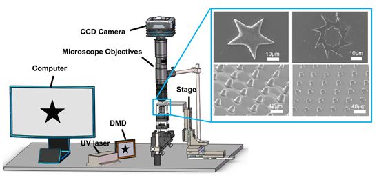
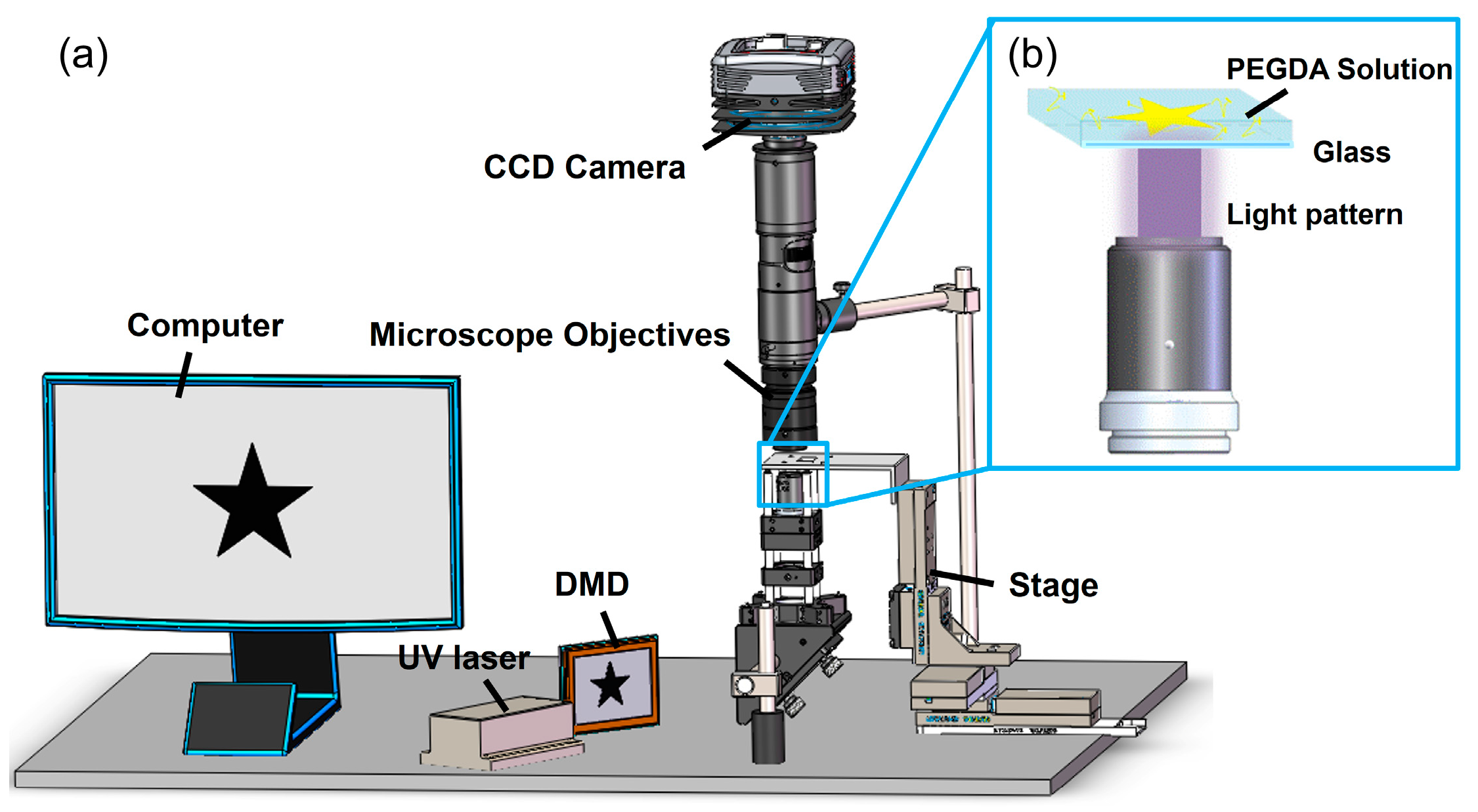
2.1. DMD-Based Hydrogel Microstructures Fabricating System

A generalized schematic of the DMD-based hydrogel microstructures fabricating system used is shown in Figure 1, which contains five basic components: UV laser (Changchun Femtosecond Technology Ltd, Changchun, China, model MW-UV-375), the DMD (Texas Instruments Ltd, Dallas, TX, USA) [34,35], projection optics, a XYZ three-axes stage (Thorlabs Inc, Newton, NJ, USA), and a charge-coupled device (CCD) camera. We adopted an ultraviolet (UV) laser coupled with adjustable power (maximum intensity is 50 mW) and a wavelength of 375 nm as the light source to enhance the accuracy of the optical path. Serving as the digital dynamic mask, the DMD, which allows us to design and pattern light, as the optical semiconductor module is the most critical part of the fabricating system. When the UV light is projected on the surface of DMD, the light can be handled by DMD with greater accuracy, efficiency, and speed than liquid crystal displays (LCDs). Micromirrors of DMD have two operating modes: the negative and positive hinged at +12° and −12°, respectively, and actions of each mirror can be controlled by the binary image which is inputted into the DMD.
Figure 1. (a) Schematic of a digital mirror device (DMD)-based modulating projection printing (DMPP) system; and (b) light-addressable poly(ethylene glycol) diacrylate (PEGDA) hydrogel polymerization.
Micromachines 06 01464 g001
To reduce the diameter of light beam and ensure fabricating precision can reach the micron level, the projection optics of the digital mirror device-based modulating projection printing (DMPP) system are designed. Vertical movement of the stage, in combination with XY movement of the platform, is used to maximize the exposure area. Prior to printing, custom-designed bitmap image sequences are inputted into the DMD, after which plain glass coated with hydrogel is placed on the platform surface. This is then illuminated by the UV laser, with patterning achieved by reflecting the laser light from a digital micro-mirror device in which each mirror turns “on” or “off” (by loading a static black and white bitmap onto the DMD). This corresponds to a change in angle of either +12° or −12° with respect to the surface of the device. The pre-polymer solution is then photo-polymerized by a projected modulating UV pattern generated through sequence stored in the DMD. The control of layer thickness produced can be modulated by adjusting the exposure time and/or the thickness of the pre-polymer solution coated onto the glass. The DMD we used consists of 1024 × 768 micromirrors and each mirror has a pixel size of 13.6 μm × 13.6 μm. So, the exposure area on the substrate, S, is therefore given as:
S = M × 13.6 × 13.6 × | β |
where β is the magnification of the projection optics and M is the number of mirrors worked. The resolution, R, can be obtained regardless of the diffraction generated by the 1 μm gap between each micromirror using:
R = 13.6 × | β |
In this study, we employed a 10× UV-focusing objective as the projection lens, which gives a β value of −0.1 and we can get an ideal resolution of our fabricating system: 1.36 μm.

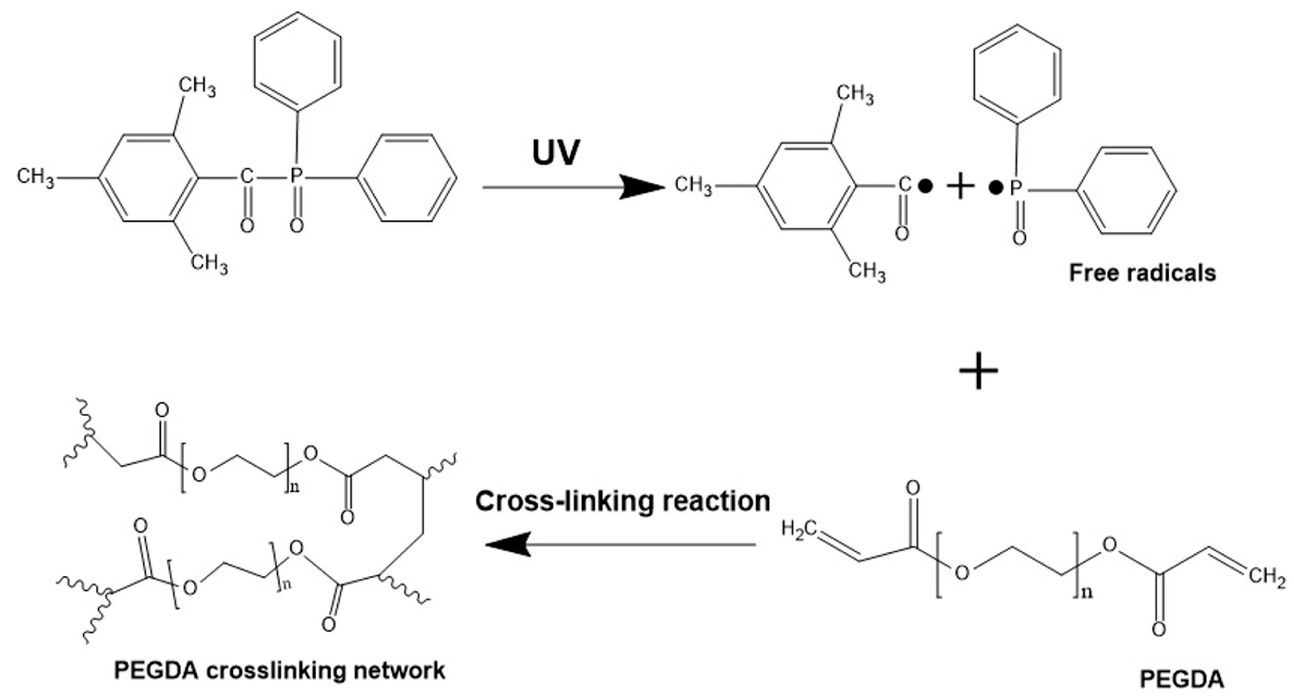
2.2. Prparing Pre-Polymer Solution

Poly(ethylene glycol) diacrylate (PEGDA) is very commonly used hydrogel which is a colloidal substance composed of water and solids [36,37]. Polymerization begins when the initiator absorbs the energy of UV light, leading to form a hydrogel crosslinking network. In our study, a 375 nm UV laser was used and to match the wavelength, diphenyl (2,4,6-trimethylbenzoyl)-phosphine oxide (TPO) was selected as the photo-initiator on the basis that it shows good absorption at 375 nm, even though it has higher absorption at shorter wavelengths. Furthermore, the photo initiator (TPO) is very difficult to dissolve in water while it can be easy to dissolve in ethyl alcohol. Therefore, to prepare the PEGDA pre-polymer solution pure PEGDA (Mn = 700, Sigma Aldrich, St. Louis, MO, USA) was first mixed with ethyl alcohol to a ratio of 1:4 (v/v), and was agitated on a magnetic stirrer at room temperature for 30 min until the PEGDA was fully dissolved. The photo initiator TPO (Sigma Aldrich) was then added to get a certain concentration of 0.5% (w/v), with a further 30 min of magnetic stirring to ensure that it was completely dissolved.
As the DMPP process relies on photo-polymerization, any free radicals generated when the TPO is exposed to UV irradiation can potentially combine and react with the PEGDA monomer (Figure 2). This cross-linking reaction contains two main steps: (1) photo-initiator (TPO) was exposed to UV irradiation and an initiator molecule was decomposed to generate two radicals; and (2) free radicals were free to react with a monomer, thereby initiating a PEGDA chain by opening its carbon-carbon bond. The polymer chains propagated via reactions with available vinyl bonds that were on monomers, or on other polymer chains. As a result of this, two chains combine to make dead polymer chains which makes growing polymer terminate. The photo-polymerization can be further controlled by varying the laser intensity, photo-initiator concentration, exposure time, or PEGDA monomer concentration.
Figure 2. PEGDA cross-linking reaction. Under ultraviolet (UV) exposure, diphenyl (2,4,6-trimethylbenzoyl)-phosphine oxide (TPO) absorbs light and generates free radicals, which combine and react with monomer molecules by opening the carbon-carbon bond. Reactive monomers then connect to form large molecules, which keep growing until two chains combine and terminate the reaction.
Micromachines 06 01464 g002

2.3. Cell Culture and Fluorescent Staining

Mouse fibroblast (L929) cells were cultured at 37 °C in a 5% CO2 constant-temperature incubator using a HycloneTM DMEM medium with high glucose (GE Life Sciences, Logan, UT, USA) supplemented with 10% fetal bovine serum and 1% penicillin/streptomycin. These cells were initially cultured on a 60 mm-diameter petri dish, and were detached using trypsin-EDTA solution and dispersed to form a cell suspension solution. The cells were subsequently seeded onto a glass substrate with patterned PEGDA, with a moderate amount of culture medium added to allow the substrate to be submerged.
Cell chains in this study were characterized by Calcein-acetoxymethyl (AM). For this, the glass with the cell chains were first washed with phosphate buffer saline (PBS) twice to remove medium. Then, add Calcein-AM into the PBS solution to attain a final concentration of 2 μmol/L. After culturing for 10 min, the cell chains were observed by a fluorescent microscope after removing Calcein-AM solution.

2.4. Measurement of Mechanical Properties

A BioScope Catalyst atomic force microscope (Bruker AFM, Camarillo, CA, USA) was employed to image and measure the Young’s modulus of the soft materials, with the probe being localized onto the surface of materials by observed through a CCD camera. Then, the force-distance curves generated were used to obtain the Young’s modulus of the surface at twenty points on each structure applying the same loading rate each measurement. The Young’s modulus was calculated using the Hertz model as [38,39]:
F sphere = 4 E R 1 / 2 δ 3 / 2 3 ( 1 ν 2 )
F cone = 2 E δ 2 tan θ π ( 1 ν 2 )
where δ is the indentation depth, ν is the Poisson ratio of the sample, θ is the half-opening angle of the probe tip, E is the Young’s modulus, R is the curvature radius of the spherical or paraboloid indenter, and F is the applied force. Only approach curves were applied to analyze in our study.
The porosity of hydrogel may influence analysis of its mechanical properties, as its mesh size increases with increase in molecular weight. Some researchers have tested this theory [40] and found that the pore size of PEGDA (Mn = 8000) is around 7 nm and so the fact that the molecular weight of PEGDA used in this study is just 700 suggests that the porosity is much smaller than 7 nm. Since the tip radius of the spherical AFM probe used was 20 nm it would, therefore, seem unlikely that could have penetrated the pores and affected the accuracy of the measurement result.

3. Results and Discussion

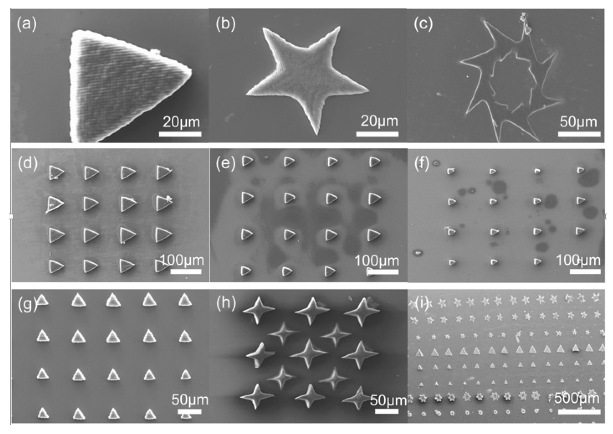
3.1. 2D Microstructure Arrays Fabricated by Printing System

The scanning electron microscope (SEM) images in Figure 3 show the various PEGDA hydrogel microstructure arrays that were created by changing the input image sequence of the DMD. Note that when compared to the designed patterned pictures, these hydrogel microstructures exhibit a very clear outlines that gives rise to a high fidelity without the need for any physical mold, mask, or complex micro-electromechanical system (MEMS). The smooth surface of the triangle, star, and gear microstructures presented in Figure 3a–c demonstrate the versatility of this fabrication method, while the 4 × 4 arrays of triangles in Figure 3d–f confirm its suitability for mass-fabrication. Figure 3g shows the uniformity of these triangular microstructure arrays, even at a size of ~20 μm, with Figure 3h showing that two different sizes of the one star-shaped microstructure can be fabricated simultaneously. Combining all of this with the three-dimensional movement of the motorized linear translation stages allows for automatic mass customization manufacturing, as show in Figure 3i.
Several UV lithography methods have recently been investigated for cell patterning. For example, a 3D stereo-lithographic printer (purchased from Rock Hill, SC, USA) has been developed to fabricate 3D hydrogels for tissue engineering [25,41,42] and biological machines [43]. However, this method of using scanning mirrors to reflect the laser is time-consuming. In contrast, the method presented here offers the advantage of greater pattern flexibility, automation, and high-throughput capability when patterning PEGDA structures. Furthermore, changes of a simple design can be implemented quickly through a software interface and exported through DMD, without any additional materials. Although, DMD is widely used in UV lithography [44,45], most printing systems are based on top-down projection which greatly limits the speed of fabricating [46]. The bottom-up projection based system presented here can overcome this shortcoming, allowing a much smaller layer thickness to be achieved.
The transverse electromagnetic mode (TEM00) of the UV laser used possesses a property of near-Gaussian profile, and so the intensity distribution of beam is in concordance with the Gaussian distribution. In other words, the intensity becomes stronger with the decrease of distance from the beam center. This Gaussian distribution of the beam is in correspondence with the microstructure arrays fabricated from a single-exposure using a binary picture, with the central circle in Figure 4a having a diameter of 59.29 ± 0.24 μm, while the diameter of the circle at the edge is 54.1 ± 0.23 μm. As shown in Figure 4b, the diameters of circular microstructures growing in the same line also exhibit a Gaussian distribution, with the size of the array increasing with optical intensity when the exposure time is fixed.
Figure 3. Scanning electron microscope (SEM) images of different microstructures produced by DMPP. (ac) triangle, star, and gear; (df) 4 × 4 arrays of triangles of different sizes; (gi) arrays of different shapes.
Micromachines 06 01464 g003
Figure 4. (a) SEM image and (b) plot showing the Gaussian variation in circle diameter with location of an array produced by a single-exposure using a binary picture (horizontal ordinate represents microstructures in different fabricating locations).
Micromachines 06 01464 g004

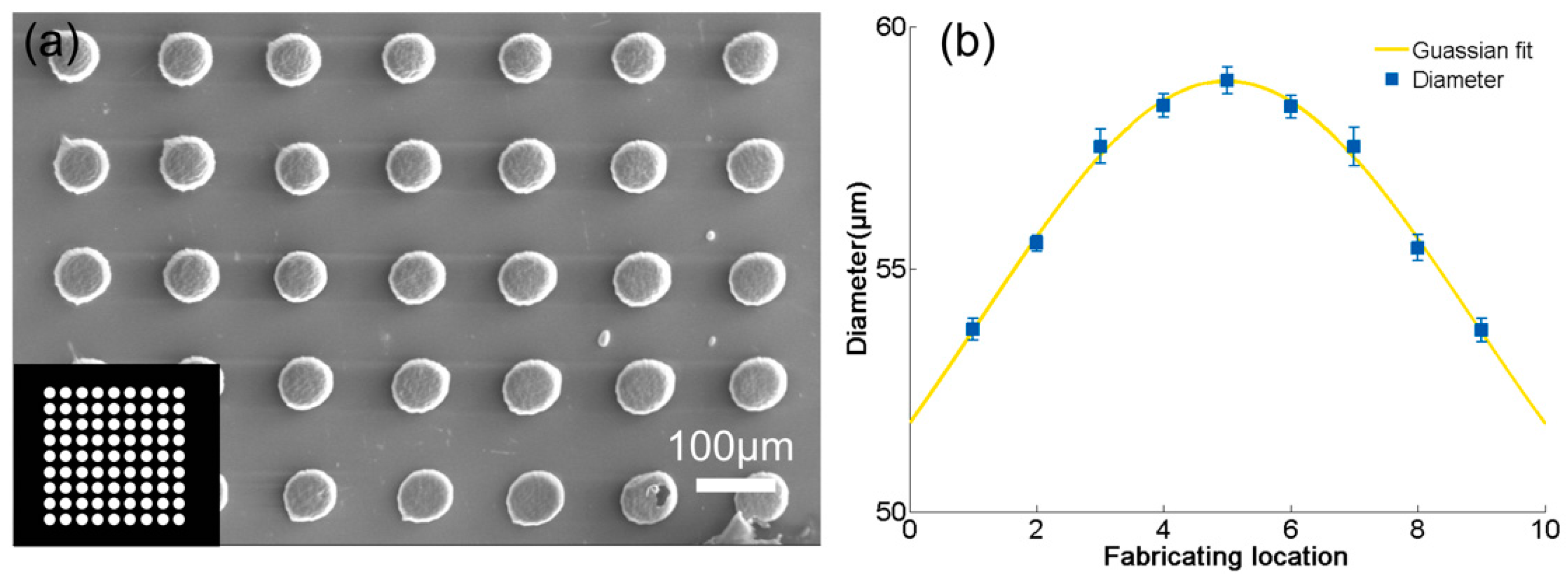
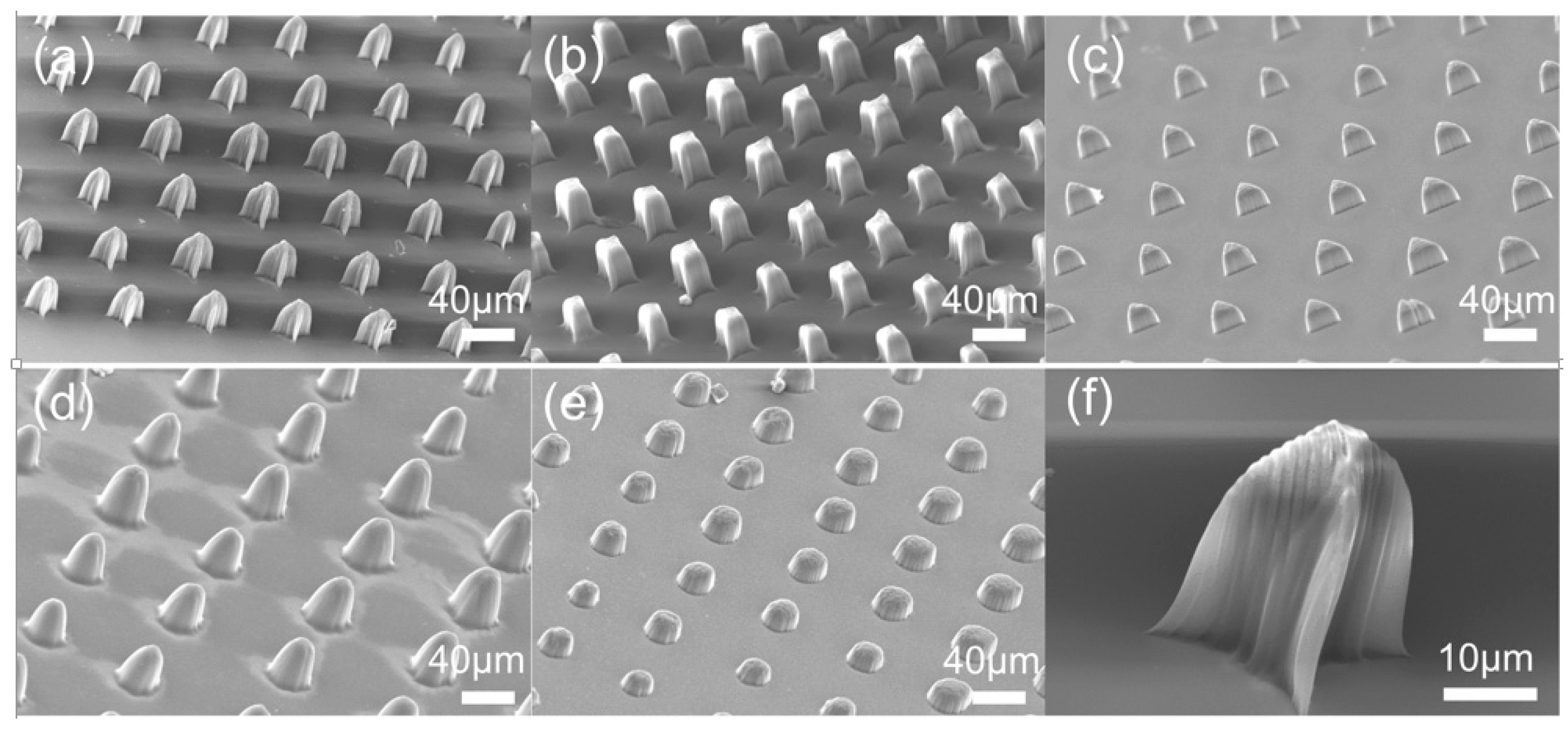
3.2. Micropillar Array Fabrication

Micropillar arrays show great promise for use in cell-growth control, MEMS and microfluidic devices, and so the DMPP system was used to fabricate the star, square, triangle, cone, and column arrays shown in Figure 5a–e. The size of these micropillar structures was about 20 μm with a good definition and the height was about 40 μm. Figure 5f shows a micrograph of a single micropillar with angular side walls. The results confirm that the DMPP system developed can fabricate microstructure arrays rapidly and effectively, with mass production being achievable by combining with XY movement of the platform and increasing an appropriate amount of rows and columns in designed images.
Figure 5. SEM images of (ae) star, square, triangle, cone, and column micropillar arrays; and (f) a single triangular micropillar with angular side walls.
Micromachines 06 01464 g005

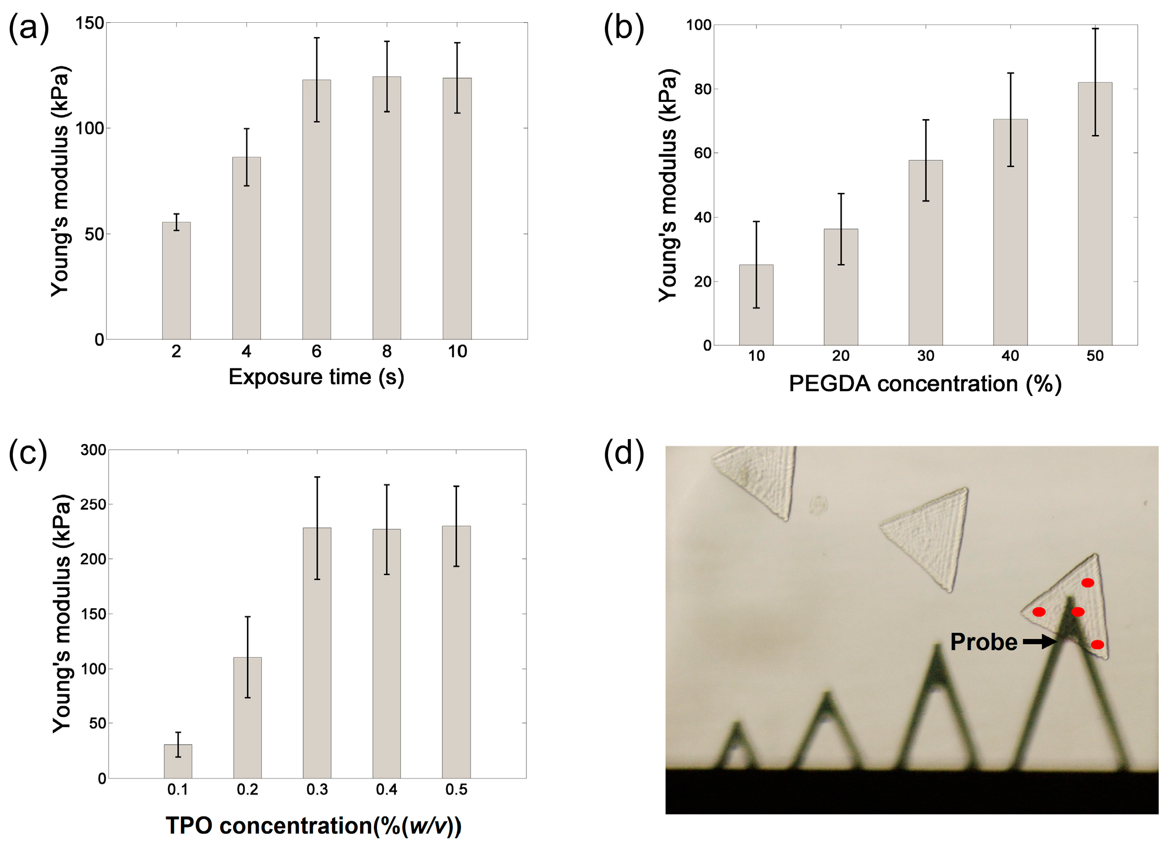
3.3. Mechanical Properties of Hydrogel Microstructures

The influences of PEGDA concentration, TPO concentration, and UV laser exposure time on the crosslinking density are reflected in the mechanical properties of the microstructures shown in Figure 6. Triangle structures with a thickness of 100 ± 5 μm were fabricated for measuring the mechanical properties of hydrogel microstructures. Around 50 patterns in total were measured at four different positions (four read points on each pattern as shown in Figure 6d) on each pattern, with each pattern obtained under different fabricating conditions. It was observed that when the concentration of PEGDA (30%), the light intensity (53.33 mW/cm2), and the concentration of TPO (0.3%) remain fixed (Figure 6a), the microstructure becomes stiffer with increasing exposure time during the first 6 s. Beyond this point, there is no change in the mechanical properties of the structure, suggesting that the cross-linking reaction has completed and any additional light exposure is useless. When the concentration of TPO, light density and exposure time are fixed (Figure 6b), increasing the PEGDA concentration causes the structure to become harder, reaching a Young’s modulus of 85 kPa with a PEGDA concentration of 50%. The change in mechanical properties with TPO concentration shown in Figure 6c reveals that the Young’s modulus remains unchanged at concentrations above 0.3%, which, as discussed above, can be attributed to the role played by free radicals in the cross-linking reaction. Specifically, once the concentration of free radicals generated from the TPO is sufficient to cure the exposed area of polymer, any further increase will not influence the cross-linking reaction.
Figure 6. Change in Young’s modulus with (a) exposure time; (b) PEGDA concentration; (c) TPO concentration; and (d) optical microscopy image showing the measurement of these mechanical properties using an atomic force microscopy probe and the red points are the four different positions which were measured.
Micromachines 06 01464 g006

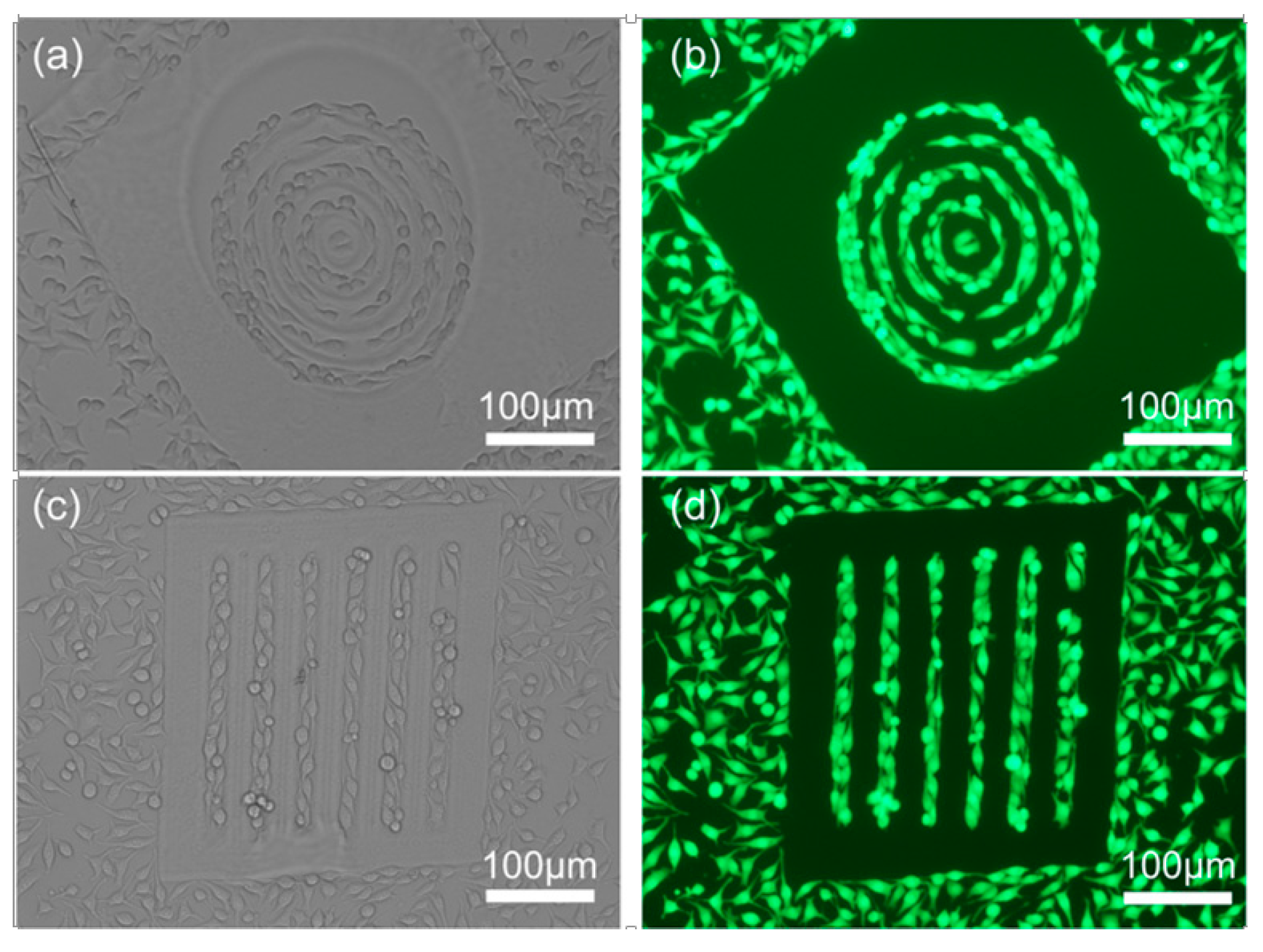
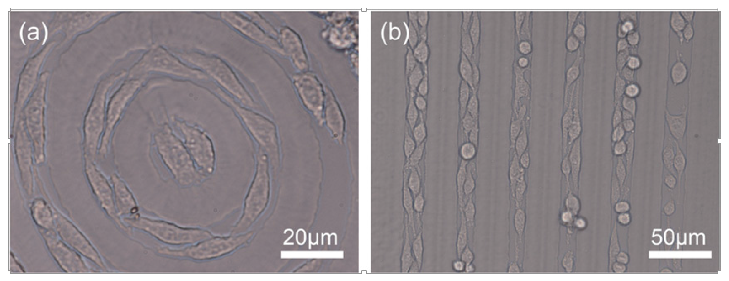
3.4. Formation of Cell Chains

Cured PEGDA has unique characteristics such as biocompatibility and nonimmunogenecity. Additionally, PEGDA-cured film can resist protein adsorption. The property of PEGDA-coated film which can hinder cell adhesion makes it possible to guide cell growth on the hollow area of the pattern, thus, providing a method to study the cell interaction. To this end, PEGDA microstructures were fabricated to specific shapes using our DMPP system, to which were added L929 cells cultured in a petri dish. After two days, different cell chains were observed to form on the different fabricated microstructures as shown in Figure 7.
Cell growth was restricted to the hollow area of the patterned PEGDA, which indicates that the shape of the PEGDA hollow area can influence the cell morphology. As shown in Figure 8, circular and linear PEGDA hollow shapes were patterned on common glass and the cell morphology was observed by optical microscopy after culturing for 2 days. Note that in both cases the cells grow in a shape that closely approximates that of the PEGDA pattern.
Figure 7. Different L929 cell chains formed by patterned PEGDA hydrogel. (a) Optical microscopic image of circular cell chains; (b) corresponding fluorescent image; (c) optical microscopic image of linear cell chains; and (d) the corresponding fluorescent image. Scale bars are 100 μm.
Micromachines 06 01464 g007
Figure 8. Cell morphology regulation by patterned hydrogel. (a) Shapes of cells growing in circular structures changes into round shape after two days culture; and (b) shapes of cells growing in linear structures change into long and narrow shapes.
Micromachines 06 01464 g008

4. Conclusions

This study has demonstrated the effectiveness of using a UV-induced method based on a DMD dynamic digital mask for fabricating PEGDA hydrogel microstructure patterns with different shapes and sizes. Using our method, dense microstructures with sharp edges can be achieved in a short period of time (<5 s), representing a significant improvement in performance over existing techniques. The exposure time, PEGDA concentration, and TPO concentration have all been identified as influential factors on the mechanical properties of the fabricated structure. Furthermore, cell chains have been formed using this method to study cell morphology and the interaction between neighboring cells. We believe that the UV-induced hydrogel fabrication technology we provide here has great potential in tissue engineering and microsystems, or combining with microfluidics to target the specific microenvironment of tumors in the future.

Acknowledgments

This research work was partially supported by the National Natural Science Foundation of China (Project No. 61302003, 61475183 and 61503258), the CAS/SAFEA International Partnership Program for Creative Research Teams and the Instrument Developing Project of the Chinese Academy of Sciences (Grant No. yz201339).

Author Contributions

Wenguang Yang, Haibo Yu, Yuechao Wang and Lianqing Liu proposed the idea; Wenguang Yang, Haibo Yu and Lianqing Liu performed the research; Wenguang Yang, Haibo Yu and Wenfeng Liang prepared the manuscript.

Conflicts of Interest

The authors declare no conflict of interest.

References

  1. Khademhosseini, A.; Langer, R. Microengineered hydrogels for tissue engineering. Biomaterials 2007, 28, 5087–5092. [Google Scholar] [CrossRef] [PubMed]
  2. Hwang, C.M.; Sant, S.; Masaeli, M.; Kachouie, N.N.; Zamanian, B.; Lee, S.H.; Khademhosseini, A. Fabrication of three-dimensional porous cell-laden hydrogel for tissue engineering. Biofabrication 2010, 2, 035003. [Google Scholar] [CrossRef] [PubMed]
  3. Murphy, S.V.; Atala, A. 3D bioprinting of tissues and organs. Nat. Biotechnol. 2014, 32, 773–785. [Google Scholar] [CrossRef] [PubMed]
  4. Yang, W.; Yu, H.; Wei, F.; Li, G.; Wang, Y.; Liu, L. Selective pattern of cancer cell accumulation and growth using UV modulating printing of hydrogels. Biomed. Microdevices 2015, 17, 1–8. [Google Scholar] [CrossRef] [PubMed]
  5. Qiu, Y.; Park, K. Environment-sensitive hydrogels for drug delivery. Adv. Drug Deliv. Rev. 2012, 64, 49–60. [Google Scholar] [CrossRef]
  6. Li, J.J.; Guo, S.Z.; Wang, M.; Ye, L.; Yao, F.L. Poly(lactic acid)/poly(ethylene glycol) block copolymer based shell or core cross-linked micelles for controlled release of hydrophobic drug. RSC Adv. 2015, 5, 19484–19492. [Google Scholar] [CrossRef]
  7. Dang, S.M.; Kyba, M.; Perlingeiro, R.; Daley, G.Q.; Zandstra, P.W. Efficiency of embryoid body formation and hematopoietic development from embryonic stem cells in different culture systems. Biotechnol. Bioeng. 2002, 78, 442–453. [Google Scholar] [CrossRef] [PubMed]
  8. Buenger, D.; Topuz, F.; Groll, J. Hydrogels in sensing applications. Prog. Polym. Sci. 2012, 37, 1678–1719. [Google Scholar] [CrossRef]
  9. Roullier, V.; Grasset, F.; Boulmedais, F.; Artzner, F.; Cador, O.; Marchi-Artzner, V. Small bioactivated magnetic quantum dot micelles. Chem. Mater. 2008, 20, 6657–6665. [Google Scholar] [CrossRef]
  10. Hu, Y.L.; Lao, Z.X.; Cumming, B.P.; Wu, D.; Li, J.W.; Liang, H.Y.; Chu, J.R.; Huang, W.H.; Gu, M. Laser printing hierarchical structures with the aid of controlled capillary-driven self-assembly. Proc. Natl. Acad. Sci. USA 2015, 112, 6876–6881. [Google Scholar] [CrossRef] [PubMed]
  11. Costa, P.; Gautrot, J.E.; Connelly, J.T. Directing cell migration using micropatterned and dynamically adhesive polymer brushes. Acta Biomater. 2014, 10, 2415–2422. [Google Scholar] [CrossRef] [PubMed]
  12. Park, K.J.; Lee, K.G.; Seok, S.; Choi, B.G.; Lee, M.K.; Park, T.J.; Park, J.Y.; Kim, D.H.; Lee, S.J. Micropillar arrays enabling single microbial cell encapsulation in hydrogels. Lab Chip 2014, 14, 1873–1879. [Google Scholar] [CrossRef] [PubMed]
  13. Liu, N.; Liang, W.F.; Liu, L.Q.; Wang, Y.C.; Mai, J.D.; Lee, G.B.; Li, W.J. Extracellular-controlled breast cancer cell formation and growth using non-UV patterned hydrogels via optically-induced electrokinetics. Lab Chip 2014, 14, 1367–1376. [Google Scholar] [CrossRef] [PubMed]
  14. Qin, D.; Xia, Y.; Whitesides, G.M. Soft lithography for micro- and nanoscale patterning. Nat. Protoc. 2010, 5, 491–502. [Google Scholar] [CrossRef] [PubMed]
  15. Suh, K.Y.; Seong, J.; Khademhosseini, A.; Laibinis, P.E.; Langer, R. A simple soft lithographic route to fabrication of poly(ethylene glycol) microstructures for protein and cell patterning. Biomaterials 2004, 25, 557–563. [Google Scholar] [CrossRef]
  16. Whitesides, G.M.; Ostuni, E.; Takayama, S.; Jiang, X.Y.; Ingber, D.E. Soft lithography in biology and biochemistry. Annu. Rev. Biomed. Eng. 2001, 3, 335–373. [Google Scholar] [CrossRef] [PubMed]
  17. Occhetta, P.; Sadr, N.; Piraino, F.; Redaelli, A.; Moretti, M.; Rasponi, M. Fabrication of 3D cell-laden hydrogel microstructures through photo-mold patterning. Biofabrication 2013, 5, 035002. [Google Scholar] [CrossRef] [PubMed]
  18. Burdick, J.A.; Khademhosseini, A.; Langer, R. Fabrication of gradient hydrogels using a microfluidics/photopolymerization process. Langmuir 2004, 20, 5153–5156. [Google Scholar] [CrossRef] [PubMed]
  19. Revzin, A.; Russell, R.J.; Yadavalli, V.K.; Koh, W.G.; Deister, C.; Hile, D.D.; Mellott, M.B.; Pishko, M.V. Fabrication of poly(ethylene glycol) hydrogel microstructures using photolithography. Langmuir 2001, 17, 5440–5447. [Google Scholar] [CrossRef] [PubMed]
  20. Kim, D.N.; Lee, W.; Koh, W.G. Micropatterning of proteins on the surface of three-dimensional poly(ethylene glycol) hydrogel microstructures. Anal. Chim. Acta 2008, 609, 59–65. [Google Scholar] [CrossRef] [PubMed]
  21. Fukuda, J.; Khademhosseini, A.; Yeo, Y.; Yang, X.; Yeh, J.; Eng, G.; Blumling, J.; Wang, C.F.; Kohane, D.S.; Langer, R. Micromolding of photocrosslinkable chitosan hydrogel for spheroid microarray and co-cultures. Biomaterials 2006, 27, 5259–5267. [Google Scholar] [CrossRef] [PubMed]
  22. Hirai, Y.; Inamoto, Y.; Sugano, K.; Tsuchiya, T.; Tabata, O. Moving mask UV lithography for three-dimensional structuring. J. Micromech. Microeng. 2007, 17, 199–206. [Google Scholar] [CrossRef]
  23. Liu, R.H.; Yu, Q.; Beebe, D.J. Fabrication and characterization of hydrogel-based microvalves. J. Microelectromech. Syst. 2002, 11, 45–53. [Google Scholar] [CrossRef]
  24. Chan, V.; Jeong, J.H.; Bajaj, P.; Collens, M.; Saif, T.; Kong, H.; Bashir, R. Multi-material bio-fabrication of hydrogel cantilevers and actuators with stereolithography. Lab Chip 2012, 12, 88–98. [Google Scholar] [CrossRef] [PubMed]
  25. Chan, V.; Zorlutuna, P.; Jeong, J.H.; Kong, H.; Bashir, R. Three-dimensional photopatterning of hydrogels using stereolithography for long-term cell encapsulation. Lab Chip 2010, 10, 2062–2070. [Google Scholar] [CrossRef] [PubMed]
  26. Watanabe, T.; Akiyama, M.; Totani, K.; Kuebler, S.M.; Stellacci, F.; Wenseleers, W.; Braun, K.; Marder, S.R.; Perry, J.W. Photoresponsive hydrogel microstructure fabricated by two-photon initiated polymerization. Adv. Funct. Mater. 2002, 12, 611–614. [Google Scholar] [CrossRef]
  27. Jhaveri, S.J.; McMullen, J.D.; Sijbesma, R.; Tan, L.S.; Zipfel, W.; Ober, C.K. Direct three-dimensional microfabrication of hydrogels via two-photon lithography in aqueous solution. Chem. Mater. 2009, 21, 2003–2006. [Google Scholar] [CrossRef] [PubMed]
  28. Ciuciu, A.I.; Cywinski, P.J. Two-photon polymerization of hydrogels—Versatile solutions to fabricate well-defined 3D structures. RSC Adv. 2014, 4, 45504–45516. [Google Scholar] [CrossRef]
  29. Bohandy, J.; Kim, B.F.; Adrian, F.J. Metal-deposition from a supported metal-film using an excimer laser. J. Appl. Phys. 1986, 60, 1538–1539. [Google Scholar] [CrossRef]
  30. Heath, D.J.; Feinaeugle, M.; Grant-Jacob, J.A.; Mills, B.; Eason, R.W. Dynamic spatial pulse shaping via a digital micromirror device for patterned laser-induced forward transfer of solid polymer films. Opt. Mater. Express 2015, 5, 1129–1136. [Google Scholar] [CrossRef]
  31. Delaney, J.T.; Liberski, A.R.; Perelaer, J.; Schubert, U.S. Reactive inkjet printing of calcium alginate hydrogel porogens—A new strategy to open-pore structured matrices with controlled geometry. Soft Matter 2010, 6, 866–869. [Google Scholar] [CrossRef]
  32. Bertassoni, L.E.; Cecconi, M.; Manoharan, V.; Nikkhah, M.; Hjortnaes, J.; Cristino, A.L.; Barabaschi, G.; Demarchi, D.; Dokmeci, M.R.; Yang, Y.Z.; et al. Hydrogel bioprinted microchannel networks for vascularization of tissue engineering constructs. Lab Chip 2014, 14, 2202–2211. [Google Scholar] [CrossRef] [PubMed]
  33. Kim, J.Y.; Brauer, N.B.; Fakhfouri, V.; Boiko, D.L.; Charbon, E.; Grutzner, G.; Brugger, J. Hybrid polymer microlens arrays with high numerical apertures fabricated using simple ink-jet printing technique. Opt. Mater. Express 2011, 1, 259–269. [Google Scholar] [CrossRef]
  34. Kim, H.C.; Yoon, H.R.; Lee, I.H.; Ko, T.J. Exposure time variation method using DMD for microstereolithography. J. Adv. Mech. Des. Syst. 2012, 6, 44–51. [Google Scholar] [CrossRef]
  35. Grogan, S.P.; Chung, P.H.; Soman, P.; Chen, P.; Lotz, M.K.; Chen, S.C.; D’Lima, D.D. Digital micromirror device projection printing system for meniscus tissue engineering. Acta Biomater. 2013, 9, 7218–7226. [Google Scholar] [CrossRef] [PubMed]
  36. Cuchiara, M.P.; Allen, A.C.B.; Chen, T.M.; Miller, J.S.; West, J.L. Multilayer microfluidic pegda hydrogels. Biomaterials 2010, 31, 5491–5497. [Google Scholar] [CrossRef] [PubMed]
  37. Durst, C.A.; Cuchiara, M.P.; Mansfield, E.G.; West, J.L.; Grande-Allen, K.J. Flexural characterization of cell encapsulated PEGDA hydrogels with applications for tissue engineered heart valves. Acta Biomater. 2011, 7, 2467–2476. [Google Scholar] [CrossRef] [PubMed]
  38. Harmon, M.E.; Kuckling, D.; Frank, C.W. Photo-cross-linkable pnipaam copolymers. 2. Effects of constraint on temperature and pH-responsive hydrogel layers. Macromolecules 2003, 36, 162–172. [Google Scholar] [CrossRef]
  39. Touhami, A.; Nysten, B.; Dufrene, Y.F. Nanoscale mapping of the elasticity of microbial cells by atomic force microscopy. Langmuir 2003, 19, 4539–4543. [Google Scholar] [CrossRef]
  40. Chiu, Y.C.; Cheng, M.H.; Engel, H.; Kao, S.W.; Larson, J.C.; Gupta, S.; Brey, E.M. The role of pore size on vascularization and tissue remodeling in peg hydrogels. Biomaterials 2011, 32, 6045–6051. [Google Scholar] [CrossRef] [PubMed]
  41. Bajaj, P.; Marchwiany, D.; Duarte, C.; Bashir, R. Patterned three-dimensional encapsulation of embryonic stem cells using dielectrophoresis and stereolithography. Adv. Healthc. Mater. 2013, 2, 450–458. [Google Scholar] [CrossRef] [PubMed]
  42. Neiman, J.A.S.; Raman, R.; Chan, V.; Rhoads, M.G.; Raredon, M.S.B.; Velazquez, J.J.; Dyer, R.L.; Bashir, R.; Hammond, P.T.; Griffith, L.G. Photopatterning of hydrogel scaffolds coupled to filter materials using stereolithography for perfused 3D culture of hepatocytes. Biotechnol. Bioeng. 2015, 112, 777–787. [Google Scholar] [CrossRef] [PubMed]
  43. Chan, V.; Park, K.; Collens, M.B.; Kong, H.; Saif, T.A.; Bashir, R. Development of miniaturized walking biological machines. Sci. Rep. 2012, 2, 857. [Google Scholar] [CrossRef] [PubMed]
  44. Zhang, A.P.; Qu, X.; Soman, P.; Hribar, K.C.; Lee, J.W.; Chen, S.C.; He, S.L. Rapid fabrication of complex 3D extracellular microenvironments by dynamic optical projection stereolithography. Adv. Mater. 2012, 24, 4266–4270. [Google Scholar] [CrossRef] [PubMed]
  45. Cha, C.Y.; Soman, P.; Zhu, W.; Nikkhah, M.; Camci-Unal, G.; Chen, S.C.; Khademhosseini, A. Structural reinforcement of cell-laden hydrogels with microfabricated three dimensional scaffolds. Biomater. Sci. 2014, 2, 703–709. [Google Scholar] [CrossRef] [PubMed]
  46. Pan, Y.Y.; Zhou, C.; Chen, Y. A fast mask projection stereolithography process for fabricating digital models in minutes. J. Manuf. Sci. Eng. 2012, 134, 051011. [Google Scholar] [CrossRef]

