Article

An Inert Continuous Microreactor for the Isolation and Analysis of a Single Microbial Cell

1
Laboratory of Chemical Biotechnology, Department of Biochemical & Chemical Engineering, TU Dortmund University, Emil-Figge-Str. 66, D-44227 Dortmund, Germany
2
LioniX B.V., Hengelosestraat 500, 7521 AN Enschede, The Netherlands
3
Department Solar Materials, Helmholtz Centre for Environmental Research (UFZ), Permoser Str. 15, D-04318 Leipzig, Germany
*
Authors to whom correspondence should be addressed.
Micromachines 2015, 6(12), 1836-1855; https://doi.org/10.3390/mi6121459
Submission received: 23 October 2015 / Revised: 18 November 2015 / Accepted: 24 November 2015 / Published: 30 November 2015
(This article belongs to the Special Issue Advances in Microfluidic Devices for Cell Handling and Analysis)

Abstract

:
Studying biological phenomena of individual cells is enabled by matching the scales of microbes and cultivation devices. We present a versatile, chemically inert microfluidic lab-on-a-chip (LOC) device for biological and chemical analyses of isolated microorganisms. It is based on the Envirostat concept and guarantees constant environmental conditions. A new manufacturing process for direct fusion bonding chips with functional microelectrodes for selective and gentle cell manipulation via negative dielectrophoresis (nDEP) was generated. The resulting LOC system offered a defined surface chemistry and exceptional operational stability, maintaining its structural integrity even after harsh chemical treatment. The microelectrode structures remained fully functional after thermal bonding and were proven to be efficient for single-cell trapping via nDEP. The microfluidic network consisted solely of glass, which led to enhanced chip reusability and minimized interaction of the material with chemical and biological compounds. We validated the LOC for single-cell studies with the amino acid secreting bacterium Corynebacterium glutamicum. Intracellular l-lysine production dynamics of individual bacteria were monitored based on a genetically encoded fluorescent nanosensor. The results demonstrate the applicability of the presented LOC for pioneering chemical and biological studies, where robustness and chemically inert surfaces are crucial parameters for approaching fundamental biological questions at a single-cell level.

Graphical Abstract

1. Introduction

Microfluidic lab-on-a-chip (LOC) systems, especially as miniaturized cultivation and analysis devices for microbes, open up new possibilities in biological research. Only the application of LOC technologies enables analyses of single microbes with spatiotemporal resolution, ultimately granting insights into the single cell as the basic functional unit beyond the bulk of a microbial population [1,2,3]. Moreover, microfluidic LOC systems provide the opportunity to decouple a single cell from extracellular fluctuations by means of continuous perfusion. Engineering and controlling the cellular microenvironment enables linking the physicochemical state of the surrounding with the physiological state of a cell. The description of cells in such standardized controlled microfluidic environments in LOC systems is necessary for understanding the multilevel matrix of physiology and environment [4,5].
Gaining access to the physiological dynamics of a living single cell necessitates separation, trapping and cultivation methods. Separation and trapping technologies in microfluidic LOC devices range from unspecific approaches, like dilution-to-extinction methods or compartmentalization in droplets, to specific techniques with mechanic, optic or electrokinetic micromanipulation [6,7]. One method for specific cell manipulation in microfluidics is negative dielectrophoresis (nDEP), where cells are exposed to an alternating electric field [8,9]. Electrode geometries and electrical field configurations for nDEP have been studied in detail and especially 3-dimensional nDEP turned out to be very effective for cell manipulation [10]. The Envirostat system is one example, where 3-dimensional nDEP was successfully applied for single-cell separation and trapping in an octupole cage [11,12]. The Envirostat represents a microfluidic bioreactor concept supplying constant environmental conditions during the cultivation of single cells [13]. It was evolved for the contactless isolation and cultivation of various microorganisms independent of cell type or size in a precisely controlled microenvironment [12,13]. Yeast and bacterial microorganisms were cultivated in the nDEP octupole cage and the resulting growth rates were significantly higher compared to population-based experiments because of the constant microenvironmental conditions [11]. Negative influences on the cellular phenotype from the nDEP field forces in the Envirostat system were excluded by a comparative study with different single-cell cultivation systems [14]. Nevertheless, the Envirostat system suffers from application-specific restrictions as polymeric materials are used for manufacturing. The usage of polymers hampers analyses of low concentrated amounts of molecules, e.g., secreted metabolites from a single cell, by unspecific adsorption of target molecules. Such analyses require absolute cleanliness and lowest possible interaction of (bio-)molecules with chip materials. New technological concepts which lead to more robust and chemically inert systems are required to overcome these limitations and enable new possibilities in single-cell research.
Dependent on the requirements of biological applications, the choice of building materials and manufacturing method is a crucial decision. Polymers and especially polydimethylsiloxane (PDMS) are today the most favored materials for LOC manufacturing [15]. The major advantage of using PDMS is particularly the possibility to rapidly produce prototype microstructures to investigate specific biological questions [16,17]. However, PDMS exhibits properties like permeability, selective adsorption of molecules, undefined surface chemistry, and flexibility [14,17,18,19]. It is generally possible to overcome the problems of permeability and adsorption by hydration and plasma-treatment [20]. However, those functionalities generated on the polymer surface are not stable and change within hours [21,22]. These characteristics limit its application for the construction of single-cell LOC devices [15,18,19,23]. Furthermore, the integration of functional elements like 3-dimensional electrodes or sensors into microfluidic PDMS structures is difficult [24]. This aspect might become problematic when the biological question requires elements to actively manipulate the cells to be analyzed. An alternative material for LOC manufacturing is glass, which is chemically and mechanically stable, cleanable and allows the integration of functional elements [15]. However, the usage of glass has drawbacks in terms of higher production costs and elaborate and time-consuming manufacturing [25,26]. Manufacturing of glass LOC devices with implemented electrodes for nDEP implicates a multistage production process, including electrode formation, creation of microchannels via etching or an additional intermediate layer, substrate bonding, and channel opening for microfluidic connections [27]. When functional electrodes are integrated in the LOC device’s microchannels, adhesive-based bonding is the method of choice, which is a robust, reasonably priced, simple production route compared to other bonding methods [28]. However, fluids are in direct contact with polymers in the case of adhesive-based bonding, leading to selective adsorption of (bio‑)molecules and time-dependent surface alterations during single-cell analyses. This is in contrast to direct fusion-bonded LOC devices, which do not require adhesives for bonding, but provide high bond strength, a defined surface chemistry, and chemical stability [25]. This manufacturing method results in devices which are robust against harsh chemical treatment required for clean experimental conditions. However, direct fusion-bonded LOC devices involve complex production processes for microchannel etching, before bonding at high temperature (>800 °C) is applied [29]. The high-temperature bonding step is critical when electrodes are integrated in the LOC device, because electrode metals are typically heat-sensitive [30]. Despite these challenges, we established a method for manufacturing a new Envirostat system with a direct fusion bonding process, which open up new possibilities for single-cell analyses such as, for example, secretome analyses.
This paper presents a new microfluidic LOC system. It is based on the Envirostat concept and manufactured via direct fusion bonding assuring chemical and mechanical stability and enabling new analytical possibilities. A novel manufacturing process was designed that resulted in glass chips that contained microfluidic channels and microelectrodes for single-cell separation and trapping. The functionality of electrodes was maintained after high-temperature fusion bonding and cell separation and trapping was proven to be highly reliable. Furthermore, the functionality and applicability of the LOC device was validated with growth and productivity analyses of amino acid secreting bacterium Corynebacterium glutamicum. The new LOC system opens the door to advanced single-cell research requiring chemically inert surfaces.

2. Experimental Section
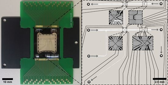
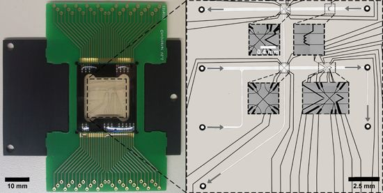
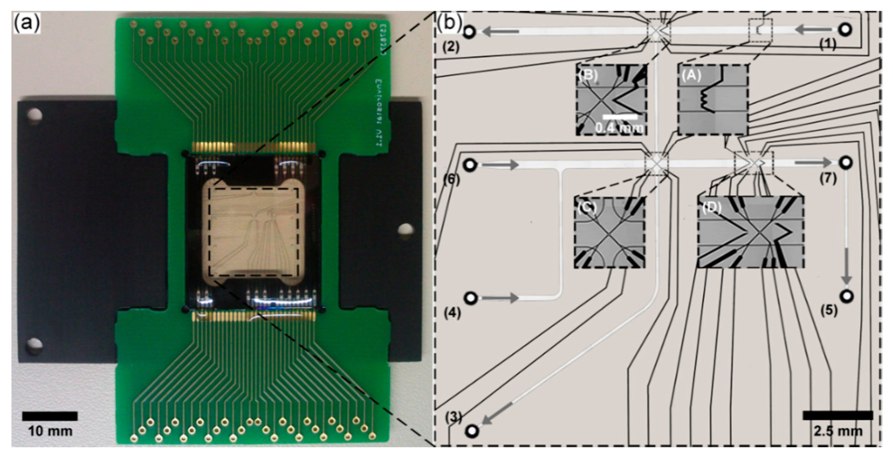
2.1. LOC Design

The microchannel and microelectrode structures of the microchip were designed with AutoCAD Mechanical 2012 (.dxf 2012, Autodesk, Inc., San Rafael, CA, USA). The AutoCAD design was transferred in the layout editor CleWin 5 (PhoeniX B.V., Enschede, The Netherlands). The final design files included the layout for microfluidic channels, as well as upper and lower microelectrode structures. Two chip geometries with 12 μm and 20 μm channel heights were constructed to enable trapping of smaller cells like bacteria or larger cells like yeast or mammalian cells. The distances of the octupole cage electrodes between tip-to-tip were 12 µm for chips with channel heights of 12 μm respectively, 20 μm for chips with channel heights of 20 μm, resulting in an equidistant cubic arrangement of the electrode tips.

2.2. LOC Microfabrication

Adhesive-based bonded reference chips were manufactured based on an indirect bonding process at GeSiM mbH, Dresden, Germany, as described before [12]. Photoresist SU-8 was used as spacer material for the channel wall and restriction between two glass substrates. The adhesive PD 955 PY was used for bonding of the substrates.
The improved, glass-based LOC system presented in this study was manufactured at LioniX B.V. (Enschede, The Netherlands). Upper and lower fused silica substrates had a thickness of 500 and 175 μm, respectively (Mark Optics, Santa Ana, CA, USA). A lithographical step was employed to specify the structure for the microelectrodes. The electrode material was applied by evaporation coating using a BAK 600 Coating System (Balzers, Balzers, Liechtenstein), followed by an ultrasonic lift-off process in acetone to produce the desired electrode structures. The sandwich electrodes consisted of 10 nm Ta, 200 nm Pt, and 5 nm Ta, which were evaporated on both substrates. Passivation layers of 450 nm SiO2 were deposited on both substrates and another 50 nm SiN was added on the thicker substrate using a PEVCD process (plasmalab80Plus, Oxford Instruments, City, Abingdon, UK). Doped SiO2 layers were deposited with a height of 12 μm or 20 μm using a similar PECVD process (Plasmalabsystem 133, Oxford Instruments, Abingdon, UK). An additional lithographical step was used to define the channel structures, followed by wet etching of the channels with 20% (v/v) aqueous HF at an etch rate of 840 nm·min−1. The passivation layers on both thick and thin substrates were removed using a reactive ion etching (RIE) step (Tetske, TCO, Enschede, The Netherlands). Fluidic connections of the microchannels and exposure of the electric contacts for driving the electrodes were realized with powder blasting (iX-factory GmbH, Dortmund, Germany). Alignment and bonding of the microstructured substrates were performed with an EVG 620 Aligner tool (EV Group, St. Florian am Inn, Austria). The thermally induced direct fusion bonding step was performed at 950 °C for 2 h in an atmospheric environment while flushing with nitrogen. Substrates were loaded and unloaded at 400 °C. Temperature gradients were generally applied at a rate of 10 °C·min−1. The chips were diced using a Micro Ace 3 dicing machine (Loadpoint, Swindon, UK). The glass chip was glued to an aluminum heatsink. For electric contacting of the electrodes with external periphery, the on-chip electrode connectors were wire-bonded to a PCB contact board (Xio Photonics, Enschede, The Netherlands).

2.3. LOC Periphery

The Envirostat chip was implemented into a periphery for fluidic and electric connections. Fluidic and electric chip mounting were adapted to the newly designed glass chips [13]. Glass syringes (10 μL, ILS Innovative Labor Systeme GmbH, Stützerbach, Germany) were used as reservoirs for growth medium or fluorophore solution. Fluidic connections between syringes and microchannels consisted of fused silica capillaries with an inner diameter of 100 μm. The growth medium supply was conveyed by syringe pumps (Cetoni Nemesys, Cetoni, Korbußen, Germany). The generator for electrode operation (Cytocon 400, Perkin Elmer, Waltham, MA, USA) was controlled by the software Switch (Perkin Elmer, Waltham, MA, USA). The temperature of the chip heat-sink was continuously monitored and controlled using a TED200c temperature controller (ThorLABS, Munich, Germany) connected to two Peltier elements (CP 1.0-63-08L, MELCOR, Utrecht, The Netherlands) and a thermistor (AD590, Analog Devices, Norwood, MA, USA). The local temperature increase caused by Joule heating was taken into account when adjusting the temperature in the cultivation area.

2.4. Cell Separation and Trapping with nDEP

Microbial cells were separated and trapped using nDEP forces in a microfluidic flow. Cells experienced the nDEP field force (FnDEP) and the Stokes’ drag force (FD) caused by the volume flow. For cell deflection or trapping FnDEP (N) had to be higher than FD (N) (Equation (1)).
F D < F nDEP
The drag force FD (N) can be expressed as follows:
F D = 6 π η v r
where η (Pa·s) is the dynamic viscosity, ν (m·s−1) is the relative velocity, and r (m) is the particle radius. The dielectric force FDEP (N) can be expressed as follows:
F DEP = 2 π ε m r 3 R e ( f CM ) E rms 2
where εm (F·m−1) is the relative dielectric constant, r (m) is the particle radius, Re(fCM) is the real component of the Clausius-Mossotti factor fCM (m3·mol−1) (Equation (4)), ∇ is the Nabla operator, and Erms (V·m−1) is the root mean square of the electric field. The Clausius-Mossotti factor fCM (-) is expressed as follows:
f CM = ( ε p ε m ) / ( ε p + 2 ε m )
where ε′p (-) is the complex permittivity of the particle, and ε′m (-) is the complex permittivity of the medium. The complex permittivity ε′ (-) is expressed as follows:
ε = ε j σ / ω
where ε (F·m−1) is the permittivity, j is the imaginary unit, σ (S·m−1) is the conductivity, and ω (s−1) is the angular frequency of the electric field.
Next to the nDEP field force (FnDEP) and the Stokes’ drag force (FD), cells experience the gravitational force (FG) (N) (Equation (6)), counteracted by the buoyancy force (FB) (N) (Equation (7)).
F G = ρ c V c g
F B = ρ f V c g
In these equations, ρc (kg·m−3) is the cell density, ρf (kg·m−3) is the fluid density, Vc (m3) is the cell volume, and g (m·s−2) is the gravity. Cell sedimentation occurs when the gravitation force is higher than the buoyancy force. Cells, which are trapped in the nDEP octupole cage, additionally experience the nDEP field force in vertical direction avoiding cell sedimentation during long-term cultivations [31,32,33].

2.5. Microscopy

Images were taken with a high-resolution monochrome video camera AxioCam MRm Rev. 3 (Carl Zeiss Microscopy GmbH, Jena, Germany) coupled to a Zeiss Observer D1 microscope (Carl Zeiss Microscopy GmbH) and processed with AxioVision Rel. 4.8.2 Software (Carl Zeiss Microscopy GmbH). The microscope was equipped with appropriate high numerical aperture objectives, a vis-LED lamp for bright field imaging, and a fluorescence light source HXP 120 C for fluorescence imaging. The light intensity of the fluorescence light source was attenuated to 2%. Filter sets for DsRed (Filter Set 43 HE, Carl Zeiss Microscopy GmbH), eGFP (Filter Set 38 HE, Carl Zeiss Microscopy GmbH) and DAPI (Filter Set 49 DAPI, Carl Zeiss Microscopy GmbH) were used for fluorescence imaging.
Images for the determination of Joule heating in the adhesive-based bonded chip were taken with a CCD-camera (EHDkamPro02, EHD Imaging, Damme, Germany) coupled to an Olympus IX71 microscope (Olympus Deutschland GmbH, Hamburg, Germany). Fluorescence images were analyzed via Wasabi Imaging Software (Hamamatsu Photonics Deutschland GmbH, Herrsching am Ammersee, Germany).

2.6. Comparative Characterization of the LOC Device

The LOC characteristics were evaluated in terms of electrode functionality, solvent resistance, pressure resistance and the adsorption characteristics of biomolecules.
The electrode functionality was tested by quantifying the current-induced temperature shift dependent on voltages. Rhodamine B, a temperature dependent fluorescence dye, was chosen for in situ thermometry. An increase in temperature leads to a fluorescence intensity decrease in micrometer spatial resolution and millisecond time resolution [34]. 40 μM Rhodamine B in aqueous NaCl solution with a conductivity of 10 mS·cm−1 was used for temperature measurements. The chip was continuously flushed with Rhodamine B solution at a volumetric flow rate of 519 pL·s−1. Fluorescence intensities of the Rhodamine B solution were measured with a DsRed filter set (Filter Set 43 HE, Carl Zeiss Microscopy GmbH) for the direct fusion-bonded LOC device. Pictures were taken at a total magnification of 400× and an exposure time of 500 ms. Fluorescence intensities were measured with a DsRed filter set and exposed to the light for 5 s for the adhesive-based bonded LOC device. The higher exposure time compared to the direct fusion bonded LOC device was required because the shutter was opened and closed manually in the microscopic set-up of the Olympus IX71. The results of the two microscopic set-ups were normalized to fluorescence intensities at 25 °C. Fluorescence intensities were measured in the cell trapping area between the tips of the electrodes. A correlation of Rhodamine B and chip temperature was determined by external regulation of the chip temperature. The extent of Joule heating was quantified for voltages ranging from 0 to 3.5 Vrms at a constant frequency of 6.25 MHz and with rotating electrode driving mode RotX [35,36]. Fluorescence images were taken 5 s after voltage adjustment. The temperature shift ΔT (K) is calculated using Equation (8) according to Fourier’s law (for detailed information and mathematical derivation, please refer to Jaeger et al. [35]).
Δ T = ( k σ 0 U rms 2 ) / ( 1 α k σ 0 U rms 2 )
In Equation (8), k (-) is the correction factor, σ0 (S·m−1) is the electric conductivity at room temperature, Urms (V) is the voltage, and α is 0.022 K−1 [35]. The correction factor k (-) was used as a comparison value of the considered LOC devices. All fluorescence measurements were done fivefold and normalized to fluorescence intensities at 25 °C.
Chemical resistance and swelling behavior of the chips were tested by exposing the microfluidic channels to water (10 min exposure time), 70% (v/v) ethanol (15 min exposure time), 20% (v/v) isopropanol (10 min exposure time), 1 M sodium hydroxide (10 min exposure time).
The pressure resistance of the chips was validated by determining the total volume flexibility in fL as a measure for channel deformation. The filled channels were pressurized at 1 bar and the resulting deformation was determined using microscopic image analysis.
Adsorption of organic and biological molecules was evaluated with the fluorescent dye Rhodamine B and fluorescein isothiocyanate conjugate labeled albumin (FITC-albumin). Rhodamine B (MW = 479 g·mol−1) was used at a concentration of 40 μM in 0.9 g·L−1 NaCl. FITC-albumin (MW = 6 kDa) was applied at a concentration of 1 mg·mL−1 in 10 mM Tris buffer adjusted to pH 7.5. The solutions were sequentially flushed into the chip and incubated for 4 h. After incubation, the chips were rinsed for 45 min with water and fluorescence images were taken to visualize adsorbed molecules. Fluorescence intensities were measured with the microscopic equipment as described above.

2.7. Strains and Media

Four different C. glutamicum strains were cultivated and analyzed with the developed microfluidic chip system (Table 1). All investigated strains were mutants (derivatives from C. glutamicum ATCC13032) with increased l-lysine productivity except the wildtype strain C. glutamicum ATCC13032. All strains carried the sensor plasmid pSenLys, which is suitable for intracellular l-lysine quantification [37].
All strains were grown in minimal medium M10 (pH 7, conductivity 10 mS·cm−1), which is a modified CGXII minimal growth medium [38] with reduced salt concentrations, composed of (per liter) 6.108 g of (NH4)2SO4, 1.2 g of CH4N2O, 0.24 g of K2HPO4, 0.24 g of KH2PO4, 0.06 g of MgSO4·7H2O, 10 mg of CaCl2, 42 g of 3-(N-morpholino)propanesulfonic acid, 0.2 mg of biotin, 10 mg of FeSO4·7H2O, 10 mg of MnSO4·H2O, 1 mg ZnSO4·7H2O, 0.2 mg CuSO4·5H2O, 0.02 mg of NiCl2·6H2O, 5 g glucose, 30 mg protocatechuic acid, and 25 mg kanamycin. The cultivation medium was sonicated in order to devolatilize the growth medium for experiments in the LOC system. It was also sterile filtered (0.2 μm pore size) before chip usage.
Table 1. Used C. glutamicum strains and plasmids: The mutated strains contained the following point mutations: pyc(P458S) leads to increased pyruvate-carboxylase activity, hom(V59A): leads to decreased homoserine-dehydrogenase activity, lysC(T311I): feedback resistant aspartate kinase, and the deletion of Δpck encoding the phosphoenolpyruvate carboxylase.
Strain/PlasmidCharacteristicReference
C. glutamicum ATCC13032Wildtype strain, biotin-auxotroph[39]
C. glutamicum DM1728pyc(P458S), hom(V59A)[40]
C. glutamicum DM1730pyc(P458S), hom(V59A), lysC(T311I), ΔpckEvonik Industries
C. glutamicum DM1919pyc(P458S), hom(V59A), 2 copies of lysC(T311I), ΔpckEvonik Industries
pSenLysEncodes LysG and its target promoter of lysE with a transcriptional fusion to eyfp, KnR[38]

2.8. Cultivation Conditions

Population level cultivations were performed in 100 mL baffled shaking flasks, filled with 10 mL minimal medium M10. Cultivations were generally performed at 30 °C and a shaking frequency of 240 rpm (Edmund Bühler GmbH, Tübingen, Germany). Samples for microscopic image analysis and quantitative fluorometry were taken in the mid-exponential phase at an OD450 of 3, corresponding to a cell dry weight of 1.2 g·L−1.
The single-cell experiments in the Envirostat system were performed at an electrode driving voltagerms of 2.8 Vrms, a frequency of 6.25 MHz at 30 °C and a flow velocity of 28 μm·s−1, which corresponds to a volumetric flow rate of 100 pL·s−1. Precultures for single-cell experiments were inoculated in 100 mL baffled shaking flasks, supplied with 10 mL minimal medium M10 at 30 °C with a shaking frequency of 240 rpm. Cells growing in the mid-exponential growth phase were used for inoculating the chip.

3. Results and Discussion

3.1. Material Selection and Bonding Methods for an Inert nDEP-Based Single-Cell Analysis System

Mechanistic insight into the functioning of single cells requires advanced microfluidic LOC devices with materials and manufacturing processes beyond common PDMS-based chip fabrication. Both amplification-based analyses, like single-cell RNA or DNA sequencing, and downstream analyses of biomolecules from live cells or single-cell lysates demand the highest standards in terms of network cleanliness, as well as minimal interference of chip materials with target analytes. Additionally, these features are ideally combined with a selective method for cell trapping. However, selection and manufacturing of chip materials that comply with the respective application-specific requirement profiles still remain challenging tasks.
We developed a microfluidic LOC device that fulfills these requirements by combining advanced materials with a novel manufacturing procedure. The central goal for the selection of the used materials and the design of the manufacturing process was to establish an inert microfluidic bioreactor for selective single-cell analyses in a completely defined microenviroment under the terms of the Envirostat concept. All materials of the LOC device had to be resistant against harsh solutions like EtOH and NaOH, enabling cleaning-in-place protocols for the removal of contaminants, and interfering (bio-)molecules. Furthermore, transparency and low autofluorescence were central requirements for quantitative analyses of cellular fluorescence levels. The developed microfluidic LOC device contained embedded platinum electrode structures for highly selective cell trapping via nDEP within an inert microfluidic network that solely consisted of glass. Polymer-free bonding of the substrates was achieved by implementing a thermal direct fusion bonding step, while fully sustaining electrode integrity and functionality. The resulting Envirostat system was chemically and biologically compatible for maintaining an unbiased physiological state of the cell during analysis, solvent resistant for the thorough removal of contaminants, and chemically inert to sample biomolecules released from a single cell.
Glass-based LOC production processes are typically complex compared to simple molding with PDMS. Especially bonding of substrates is a process of crucial importance. Given the fact that the bonding materials are in direct contact with the fluids inside the LOC system, the choice of bonding method for the glass substrates decisively determines the applicability of the LOC device. In general, bonding of microfluidic glass chips can be distinguished between direct or adhesive-based methods [24]. In order to rationally choose a proper method for the developed Envirostat system, physical and chemical characteristics of indirect bonding strategies were compared with direct fusion bonding and evaluated in terms of their applicability for microfluidic single-cell analysis systems (Table 2).
Table 2. Comparison of characteristics between indirect (SU-8-glass, PD 955 PY-glass) and direct (glass-glass) bonding technologies.
CharacteristicsSU-8-Glass (UV Cured Polymer)PD 955 PY-Glass (Thermally Cured Polymer)Glass-Glass (Direct Fusion)
Bond strength1–2 MPa [41]>25 Mpa a~bond strength of glass (67 MPa) b
BiocompatibilityCompatible [42]CompatibleCompatible
Solvent resistanceResistantNot resistantResistant
Chemically inertInertNot inertInert
Bonding homogeneityHomogeneousHeterogeneousHomogeneous
Notes: a see datasheet PD 955 PY SMT adhesive, Heraeus; b see datasheet Quartz Glass Tubes, Heraeus.
Direct fusion bonding of fused silica substrates provides the highest bond strength and homogeneous bonding (Table 2). It is fully biocompatible, solvent resistant and chemically inert. Although SU-8 photoresist as a bonding material for glass substrates is also advantageous in terms of resistance, inertness and bonding homogeneity, it is far inferior in bonding strength compared to direct fusion bonding. Moreover, Envirostat systems that have been produced with SU-8 bonding were prone to delamination (detachment of the substrate) upon introduction of fluids into the microchannels. Indirect bonding with adhesives is a well-established process that offers simple production routes and high bond strength [43]. On the downside, adhesives are neither chemically inert, nor solvent resistant. Monomer bleeding from such adhesive might also significantly reduce the biocompatibility of this bonding method and might impact the cellular phenotype. However, the integration of electrode structures, like octupoles for nDEP trapping of cells into LOC devices with adhesive bonding, is feasible, whereas the implementation of such structures into direct fusion-bonded systems has not been possible up to now. In contrast to adhesive-based bonding methods, direct fusion bonding requires a high-temperature step, which affects electrode structure, integrity and functionality [25]. Nevertheless, direct fusion bonding of the fused silica substrates was chosen for microfluidic chip processing due to its superior properties with regard to bond strength, biocompatibility, chemical inertness and solvent resistance.

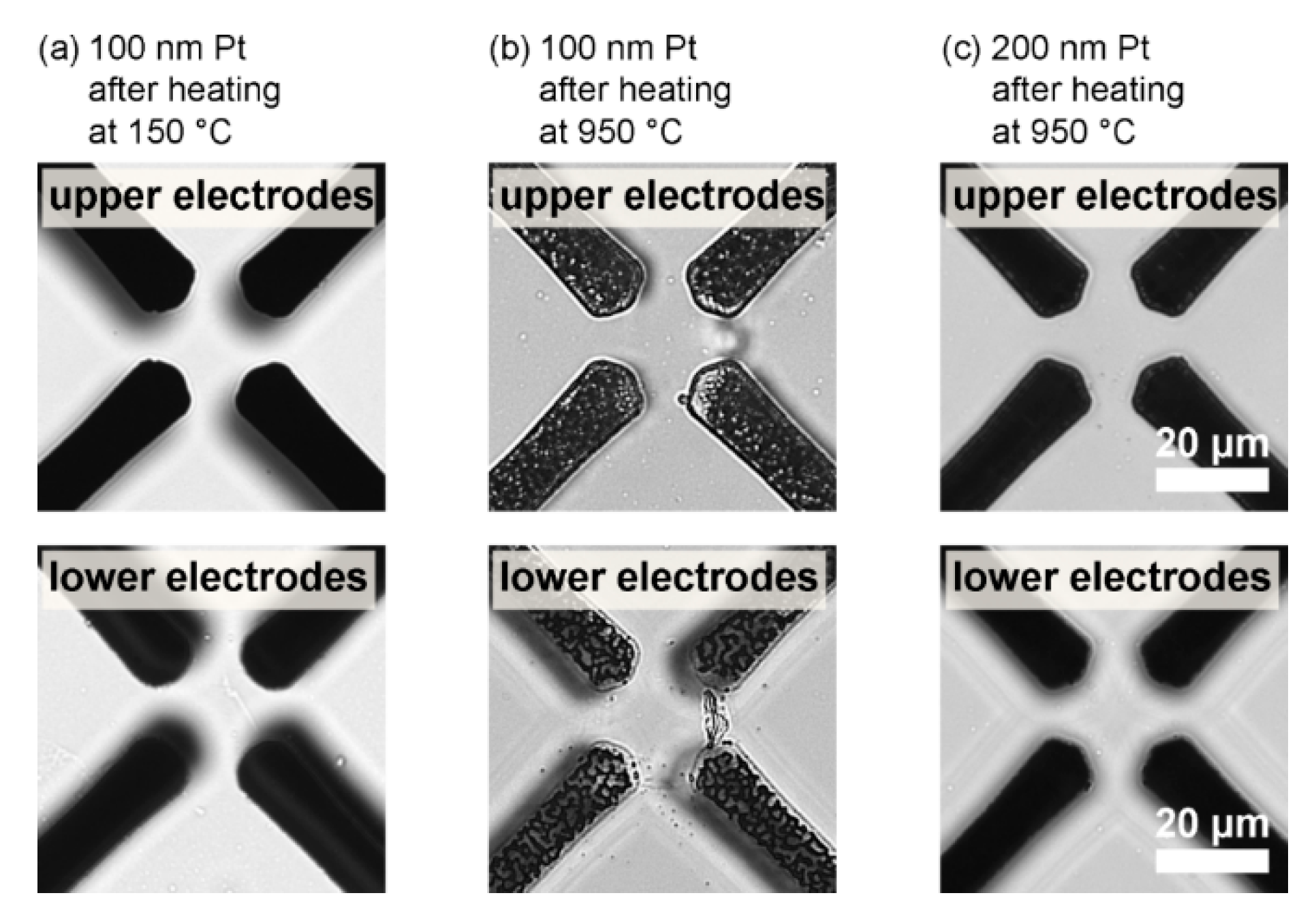
3.2. Implementation of Functional Electrodes into Direct Fusion-Bonded LOCs for nDEP Cell Trapping

Manufacturing of direct fusion-bonded glass chips is an established process in LOC microfabrication [25,29]. However, the process becomes challenging when functional electrodes for cell trapping or sensing have to be integrated. This is because direct fusion bonding requires a high-temperature step (950 °C) to covalently connect upper and lower substrate. Heat-sensitive structures like platinum electrodes within the microfluidic chip can be damaged by such high temperatures, potentially resulting in loss of their functionality or drastic increase of electrical resistance. This is due to diffusion and oxidation of the electrode layers (Pt/Ta) during heat treatment and thermal expansion, forming hillocks and voids in the electrode layers [30].
Platinum was applied as electrode material, with tantalum as an adhesion layer between platinum and glass, for the developed Envirostat system. Platinum was used because it has a good electrical conductivity, is thermally stable, ductile and resistant against corrosion. In previous revisions of the developed LOC device, the thickness of the platinum electrode was 100 nm by default. Electrodes with a thickness of 100 nm maintained their integrity and function after the hardbake bonding step (T = 150 °C) for indirect bonding with adhesive (Figure 1a). However, direct fusion bonding at a temperature of 950 °C resulted in porous and partially ablated electrodes (Figure 1b), which were drastically hampered in their cell trapping functionality. In order to counteract electrode damage as a result of the high-temperature direct fusion bonding step, the thickness of the platinum electrodes was increased to 200 nm. Indeed, this measure drastically reduced the temperature-induced damage of the electrode layer and a continuous electrode structure was retained (Figure 1c). However, a change of electrode structure is likely due to the high-temperature step for direct fusion bonding. This alteration resulted in an increased roughness of electrode surfaces. Nevertheless, the electrode functionality of the direct fusion-bonded chips was maintained and validated by comparing the cell trapping performance of the electrode structures to adhesive-based bonded chips. The nDEP cell trapping efficiency of both systems was identical at otherwise constant trapping parameters, which proved the applicability of electrode implementation in direct fusion-bonded LOC systems. Moreover, it implied that the electrical resistance of the electrodes was not affected by the high-temperature bonding step, since nDEP trapping performance reacts very sensitively to changes in electrical conductivity, which would have resulted in impaired trapping performance.
The novelty of the manufacturing process was the innovative combination of known individual fabrication steps to result in a microfluidic glass device with non-passivated functional electrodes on both sides of the microfluidic channel. The developed Envirostat system represents the first example of successfully integrated 3-dimensional electrode structures into a direct fusion-bonded microfluidic device for single-cell trapping and analysis via nDEP. All further chips used in this study were hence produced with a platinum electrode layer thickness of 200 nm.
Figure 1. Microscopic images of upper and lower cage electrodes after thermal treatment: (a) 100 nm platinum layer after heating at 150 °C; (b) 100 nm platinum layer after heating at 950 °C; (c) 200 nm platinum layer after heating at 950 °C. Images were centered on the central point of the focused electrodes.
Micromachines 06 01459 g001

3.3. LOC Design and Characterization

The Envirostat system with mounting plate and electrical contacting, as well as its microelectrode and microchannel structure, is illustrated in Figure 2a. The developed chips featured microfluidic channels with heights of 12 μm and 20 μm, respectively, including seven in- and outlets (Figure 2b). The two different channel heights equal to the electrode cage tip distances and were produced to enable stable trapping of smaller bacteria (12 μm channel height) or larger cell types like yeast cells or small mammalian cells (20 μm channels height). Inlet (1) was designed for the injection of cell suspension. Outlet ports (2) and (3) were designed to flush waste cells and waste medium out of the chip channels. Inlet (6) was dedicated to the supply of cultivation medium and port (5) represented the corresponding outlet for cultivation supernatants (perfused cultivation medium). Outlet (5) was also designed as a sampling port for compounds secreted by the microorganism. Outlet (7) allowed cell deposition for growing a population originating from the analyzed single cell. Another microfluidic channel allowed specific chemical perturbation or nutrient enrichment (inlet (4)). In order to ease microscopic analysis with a x-, y-table, the channels were orientated horizontally and vertically. Regarding the channel dimensions, a width of 300 μm was chosen for cell separation- and trapping-channels, whereas 100 μm widths were used for cell transport and waste channels. The width of separation and trapping channels was chosen on the basis of experience. The transport and waste channel width was defined to a lower value to increase flow velocity and therefore to accelerate cell transport.
The microfluidic chip offered areas with several electrode structures (Figure 2b) for retaining cells (A); for cell separation (B); cell isolation (C); and cell analysis (D). The cell retaining unit (zigzag shaped electrode) was used to hold back excess cells during separation of the target cell. The separation unit was dedicated to isolate specific target cells from an introduced cell suspension. It consisted of an nDEP octupole cage geometry for cell trapping and an additional hook electrode for channeling cells in the direction of the octupole center or for cell retaining (Figure 2bB). With these electrode structures, highly reliable cell separation and trapping via nDEP was possible. After separation, the cell of interest was transported with the fluidic flow into the lower part of the chip. Here, the cell isolation unit was implemented and can be used to isolate a cell and discard remaining preculture residues (Figure 2bC). The cell analysis unit was designed for cultivation and analysis of the target cell (Figure 2bD). It was implemented in close proximity to the outlet in order to decrease void volume of single-cell supernatant.
The designs of the microchannels and microelectrodes were kept as simple as possible, while maximizing functionality and minimizing void volumes. The developed structure of the Envirostat system allowed cell separation, cultivation and analysis, as well as medium change and supernatant sampling within one single microfluidic chip that is chemically inert and highly biocompatible.
Figure 2. The Envirostat system: (a) The microfluidic chip is directly bonded and mounted on an aluminum plate and wire-bonded to a PCB-board; (b) microscopic magnification of the chip with microfluidic channels, microelectrodes and in-/outlets. (1) Inlet for cell suspension. (2) Outlet for waste cells. (3) Outlet for waste. (4) Inlet for cultivation medium supply. (5) Outlet for cultivation medium and sampling. (6) Inlet for cultivation medium change. (7) Outlet for cell deposition. (A) Cell retaining unit, (B) cell separation unit, (C) cell isolation unit, (D) cell analysis unit.
Micromachines 06 01459 g002

3.4. Experimental Validation of Characteristics and Comparison of a Direct Fusion- and Adhesive-Bonded LOC Device

In the following, we characterized the newly developed direct fusion-bonded Envirostat system and compared it to an adhesive-based bonded LOC system. The comparative characterization comprised quantification of Joule heating, solvent and pressure resistance, as well as adsorption characteristics of the two systems.

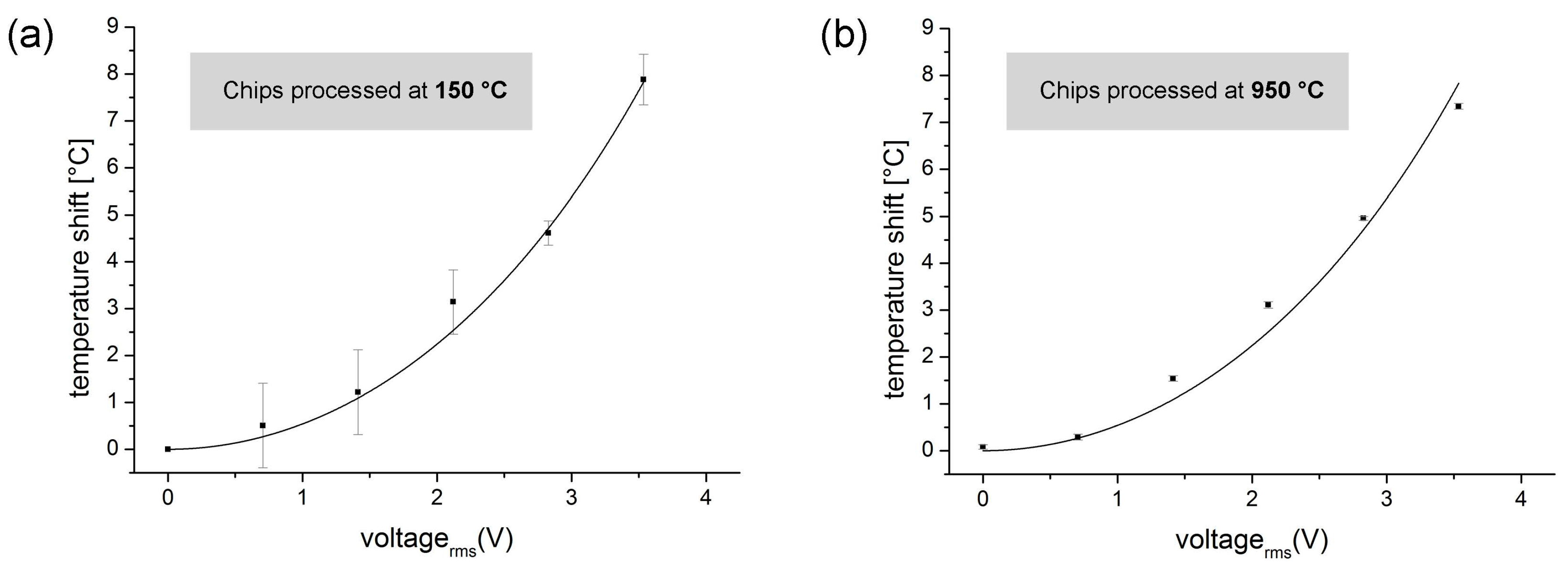
3.4.1. Quantitative Measurements of Joule Heating in a Direct Fusion- and Adhesive-Bonded LOC Device

The extent of Joule heating is an important parameter during single-cell trapping and analysis. Moreover, it allows us to draw conclusions about electrode quality. We therefore used the extent of Joule heating to verify proper electrode function of the developed LOC and to exclude changes in electrode conductivity due to the high-temperature exposure during direct fusion bonding. The adhesive-based bonded LOC device was used as reference.
Our comparison revealed that the voltage-dependent temperature development between the electrodes of the octupole cage was identical to the adhesive-based bonded chip (Figure 3). For a meaningful and simple comparison of the temperature development due to Joule heating, the fit parameter k was determined with Equation (8). The fit parameter k is dependent on electrode geometry and material, and is therefore an appropriate value to quantify Joule heating. The k values amounted 0.54 for the adhesive-based bonded LOC device and 0.53 for the direct fusion-bonded LOC device. The equal k fittings clearly showed that the high-temperature direct fusion bonding step had hardly any influence on the electrical resistance of the electrodes, implying proper functionality of electrodes. Interestingly, the thickness of platinum electrodes had no measurable effect on the Joule heating-induced temperature shift, although a dependency of Joule heating has been proposed on thin-film platinum layer thickness [44,45]. A reason for this might be that the increased thickness only compensated for an increase of the electrical resistance as a result of the high temperature bonding step.
Figure 3. Voltage dependency of the Joule heating induced temperature shift (°C) in the octupole cage of (a) adhesive-based bonded and (b) direct fusion-bonded LOC devices. The octupole cages were operated in RotX mode. The solid line represents the fitting with Equation (8) and a calculated k parameter of 0.54 (a) and 0.53 (b). All fluorescence measurements were done fivefold and normalized to fluorescence intensities at 25 °C. Standard deviations of the LOC devices differed due to the fact that the Rhodamine B fluorescence intensities were measured with different microscopic systems. The exposure to fluorescence irradiation was manually executed in case of the adhesive-based bonded LOC device, whereas the exposure was automatically performed for measurements with the direct fusion-bonded LOC device.
Micromachines 06 01459 g003

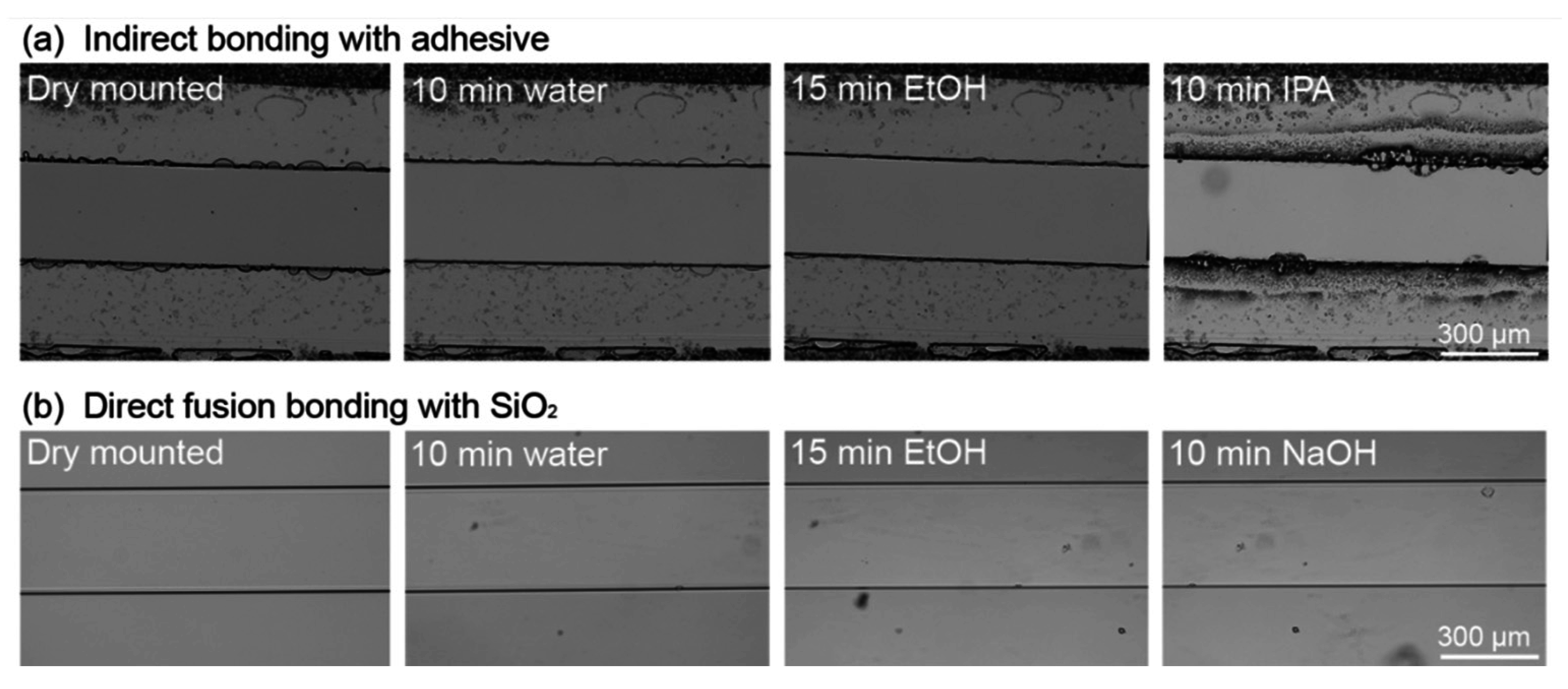
3.4.2. Solvent Resistance of a Direct Fusion- and Adhesive-Bonded LOC Device

The new Envirostat system had to provide defined conditions in every individual experiment to be in conformity with the Envirostat concept. That means it had to be sterilized before experiments and cleaned of cells, biofilms, and nutrients after every experiment. Typical sterilization solutions for killing microorganisms are 40%–70% (v/v) ethanol or 1 M sodium hydroxide for the removal of cells or extracellular polymers. The direct fusion- and adhesive-based bonded LOC devices were exposed to cleaning solutions in order to validate their solvent resistance.
The comparison revealed that harsh cleaning protocols were not applicable for the adhesive-based bonded chips (Figure 4a). The exposure of the microfluidic network to 70% (v/v) ethanol for 15 min led to significant changes in the adhesive structure due to swelling. The treatment with 20% (v/v) isopropanol for 10 min showed an even higher impact on the adhesive structure, leading to significant swelling and channel deformation. Cleaning the chip interior with 1 M sodium hydroxide led to a partial detachment of adhesive (results not shown). The direct fusion-bonded LOC device underwent the same chemical treatment procedure. In contrast to the adhesive-based bonded LOC device, its channel structure was not affected by any of the chemicals (Figure 4b). From these results, it was concluded that the presented Envirostat system can be thoroughly sterilized and cleaned.

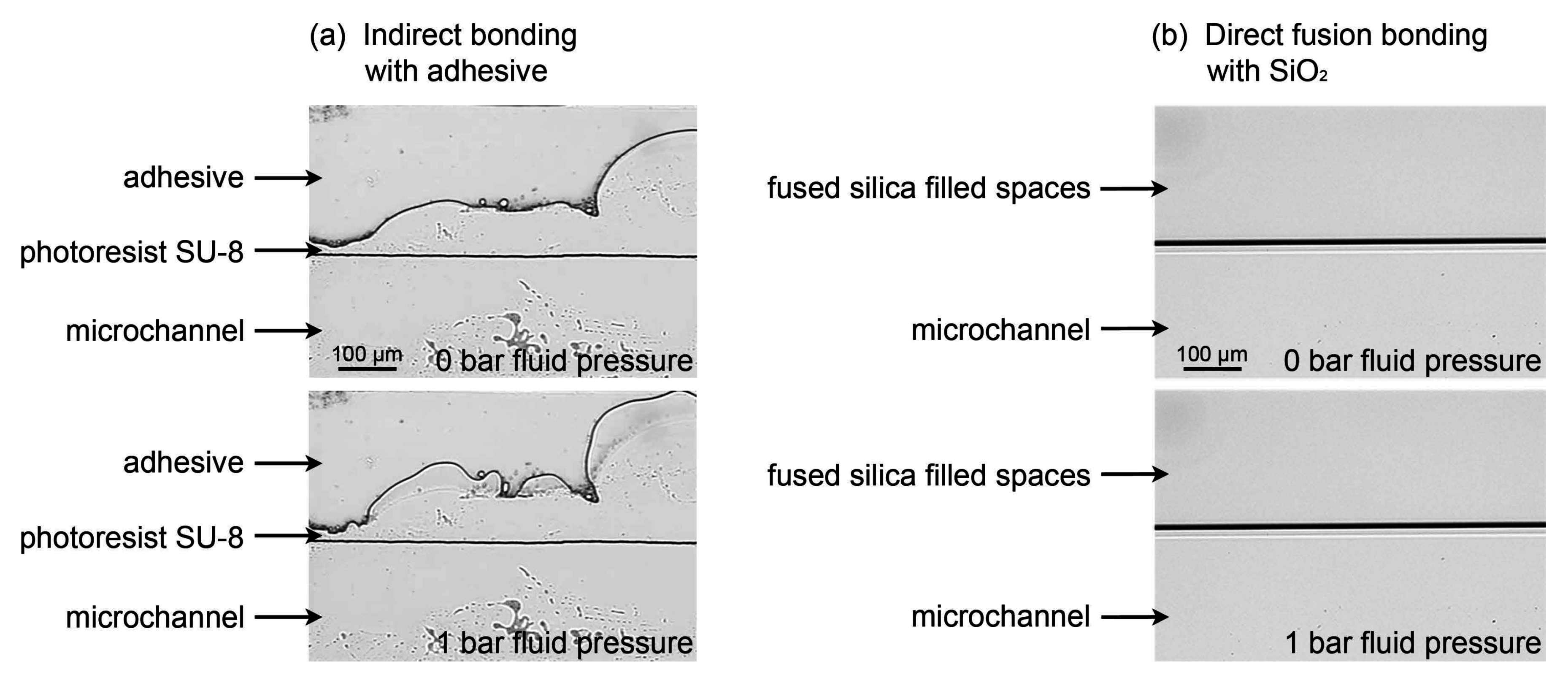
3.4.3. Pressure Resistance of a Direct Fusion- and Adhesive-Bonded LOC Device

The application of nDEP for cell manipulation in the Envirostat system required a stable microfluidic velocity profile for reliable cell trapping and fixation. Small velocity fluctuations could be caused by instable and compressible channel walls. Therefore the compressibility of channel walls upon pressurization was tested.
The new LOC device was compared to the indirect adhesive-based bonded chip (Figure 5). Movement of the adhesive interface was observed at the applied pressure of 1 bar and the compression of the adhesive resulted in a total volume change of 0.706 fL (Figure 5a). Even though the measured volume change was small compared to the total volume of the chip (265 nL), the instability of the channels resulted in velocity fluctuations in the affected channel. Next to the compression of the adhesive, a partial removal of adhesive droplets was observed when perfusing the channel. During standard cultivations at relatively low flow rates and with a resulting low fluidic pressure, pressure fluctuations were observed. The applied adhesive showed fluidic properties rather than behaving as a solid channel boundary. These undefined fluid fluctuations during cultivation often led to cell loss out of the nDEP octupole cage. In the case of direct fusion-bonded LOC devices, no channel instabilities and deformations were observed upon pressurization (Figure 5b). During cultivations, cells were occasionally lost as a result of velocity fluctuations. The enhanced stability of flow velocity profiles in the direct fusion-bonded Envirostat system compared to the adhesive-based device led to more reliable cell trapping and fixation in the nDEP octupole.
Figure 4. Chemical resistance test with cleaning solutions: (a) Adhesive-based bonding: solvent resistance test with a PD 955 PY bonded microfluidic chip; the chip was mounted in the periphery, flushed with water, 70% (v/v) ethanol and 20% (v/v) isopropanol (IPA); the PD 955 PY adhesive showed structural changes with ethanol and isopropanol treatment. (b) Direct fusion bonding: solvent resistance test with a direct fusion-bonded chip; the chip was mounted in the periphery, flushed with water, 70% (v/v) ethanol and 1 M sodium hydroxide; the channel borders did not show any effect caused by the solvents. The adhesive-based bonded LOC device was destroyed during 1 M NaOH treatment and therefore no picture could be taken. Therefore, an additional picture for IPA was supplemented.
Micromachines 06 01459 g004
Figure 5. Channels and channel walls of adhesive- and direct fusion-bonded chips. (a) The adhesive-based bonded chips consist of two glass substrates with SU-8 spacer and adhesive PD 955 PY for bonding. (b) The direct fusion-bonded chips are directly fused glass substrates. Water was introduced and images were taken at a pressure of 0 bar and 1 bar.
Micromachines 06 01459 g005

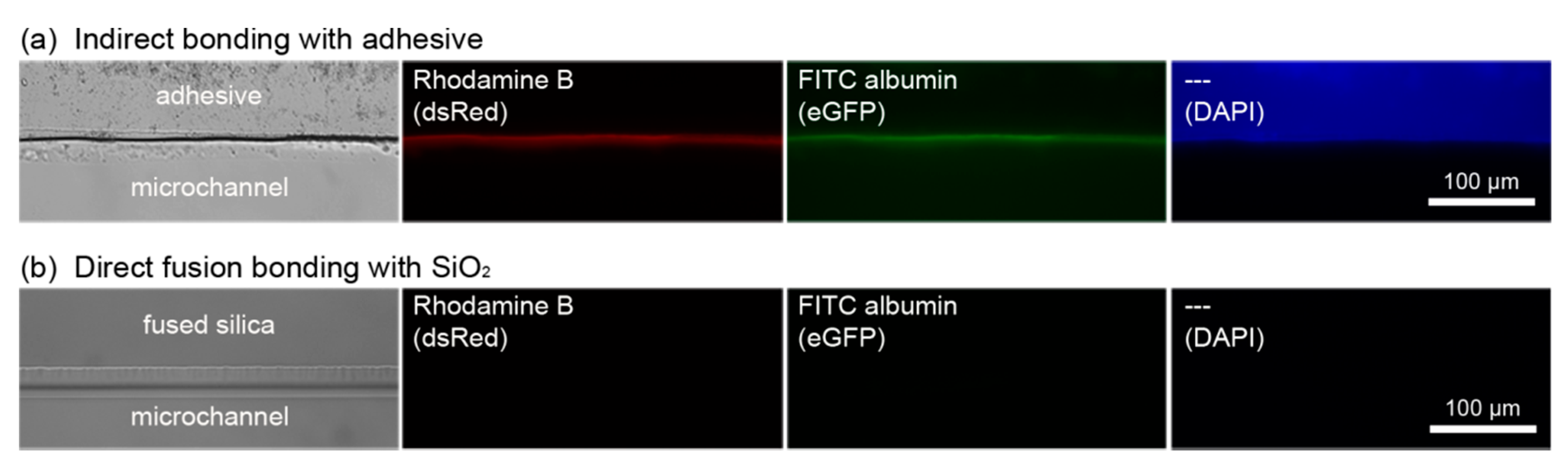
3.4.4. Adsorption of (Bio-)Molecules

The Envirostat system had to be chemically inert in order to enable defining microenvironmental conditions with known physicochemical properties for single-cell experiments. Furthermore, it had to be excluded that molecules like secreted metabolites of the cell or cell lysates might be subjected to specific adsorption. Therefore, the adsorption of (bio-)molecules was tested for the LOC systems.
Adsorption characteristics of both LOC systems were exemplarily characterized with the fluorescent dye Rhodamine B (40 μM, MW = 479 g·mol−1) and a fluorescent labeled protein FITC-albumin (1 mg·mL−1, MW = 66 kDa) as representative molecules. The adhesive-based bonded chips showed fluorescence on the surface of the channel walls, due to adsorption of fluorescent molecules (Figure 6a). Furthermore, it was observed that the adhesive PD 955 PY exhibited autofluorescence when excited with DAPI settings (λex = 365 nm, λem = 420–470 nm), which might cause high background signals and makes the detection of analytes with blue fluorescence difficult and imprecise. For the direct fusion-bonded chips, no adsorption was detected (Figure 6b).
Figure 6. (a) Microfluidic channel, manufactured with an adhesive-based bonding method using PD 955 PY. (b) Microfluidic channel manufactured with a direct fusion bonding method; from left to right: microscopic bright field image; microscopic fluorescence image, taken with DsRed filter, channels were flushed with 40 μM Rhodamine B and subsequently rinsed with water; microscopic fluorescence image, taken with eGFP filter, channels were flushed with 1 g·L−1 FITC-albumin and subsequently rinsed with water; microscopic fluorescence image, taken with DAPI filter, channels were flushed with water.
Micromachines 06 01459 g006
The results show that no molecules adsorb in detectable amounts, which led to the assumption that the new Envirostat system met the requirements for analyses of secreted metabolites of a single cell.

3.5. Application of the LOC Device for Analyses of Single-Cell Growth and Productivity

The presented Envirostat system was intended for the analyses of single cells cultivated under defined microenvironmental conditions. Single cell growth was demonstrated as a proof of principle for the functionality of the developed device. Furthermore, productivity analyses of l-lysine producing C. glutamicum showed the application range and potential of the LOC device for further single-cell analyses.

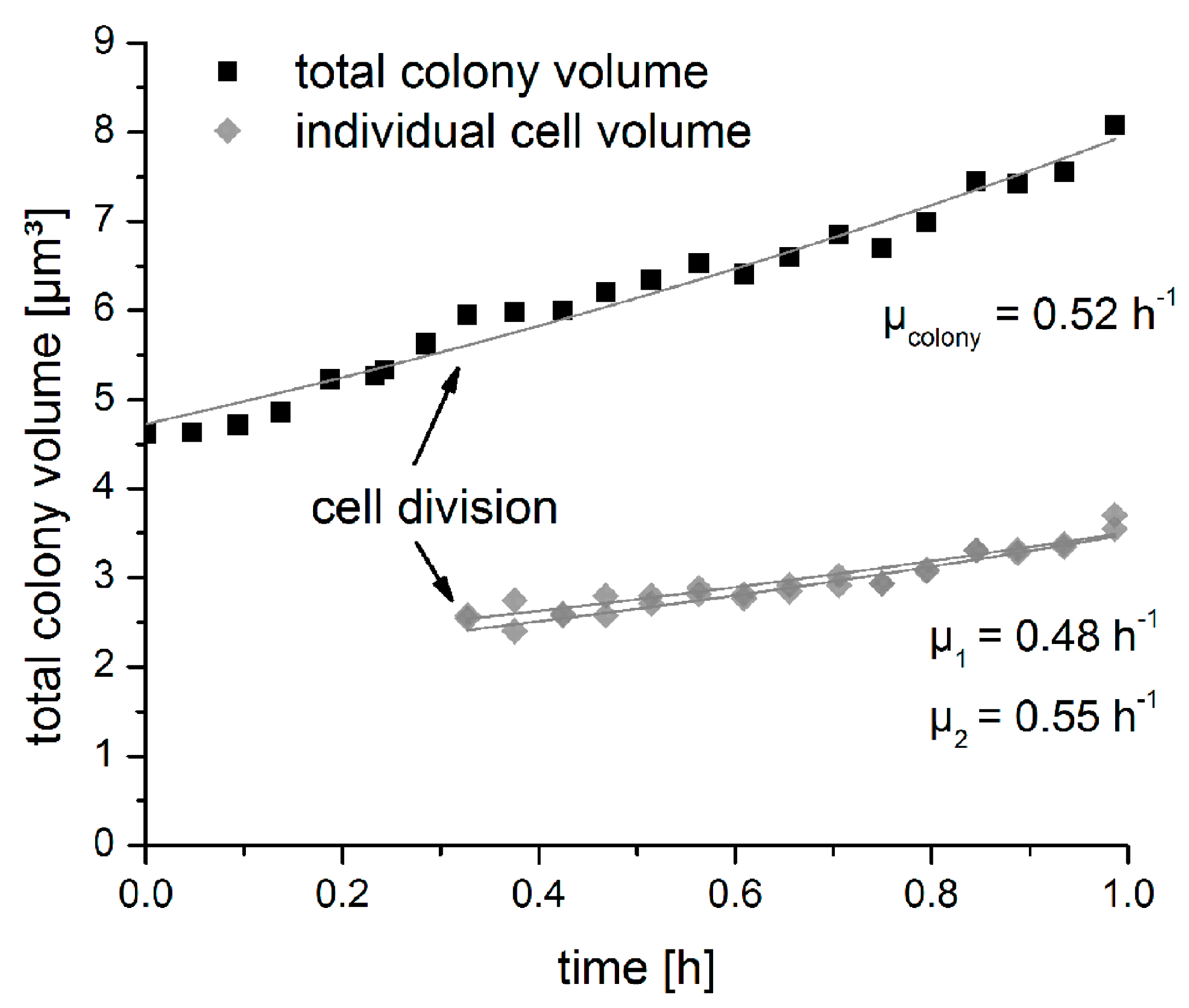
3.5.1. Growth of an Isolated Single Bacterial Cell

The intention of the growth analysis was providing evidence of Envirostat functionality for biological experiments and to gather knowledge about the cellular fitness in the system. Microbial growth is generally considered as a suitable proxy for cellular fitness [46,47]. Therefore, the new Envirostat system was applied for cultivation of the well-described bacterial strain C. glutamicum DM1730 pSenLys [37,48] and compared to specific growth rates in shake flasks. Specific volume growth rates were analyzed by measuring time-dependent cell geometries to calculate cell volumes (according to Dusny et al. [14]).
For growth analysis, a single cell was trapped in the nDEP octupole with an initial volume of 4.6 μm3. The cell volume was constantly increasing over time and resulted in a total cell volume of 8.1 μm3 after 1 h (Figure 7). The volume increase of the cell was fitted with an exponential function (R2 = 0.97) and resulted in a specific growth rate of 0.52 h−1. The trapped cell divided after 20 min and the resulting daughter cells had specific growth rates of 0.48 and 0.55 h−1. These rates were significantly higher compared to batch experiments in shake flasks, where cells were growing with a specific growth rate of 0.37 h−1 ± 0.03. Faster microbial growth in single-cell perfusion systems is a known phenomenon and most likely a result of the homogeneous extracellular environment with optimal nutrient supply and permanent removal of secreted metabolic products [11,12,49]. For C. glutamicum ATCC13032, the accumulation of acetate and the depletion of the iron chelator protocatechuic acid in batch cultivations were identified as the reason for lower specific population growth rates compared to single cell growth rates under continuous perfusion [50,51].
Figure 7. Volume growth of an initial single cell (C. glutamicum DM1730 pSenLys), trapped with nDEP in the inert LOC device. A cell was isolated, trapped and cultivated for 1 h. After 20 min the cell divided. Total colony volume and individual cell volumes were measured over time and exponentially fitted.
Micromachines 06 01459 g007
From these results it could be concluded that the cells were in a good physiological state during cultivation in the nDEP octupole cage of the Envirostat system. In conclusion, the new Envirostat system was successfully developed and applied for single-cell growth studies for the first time.

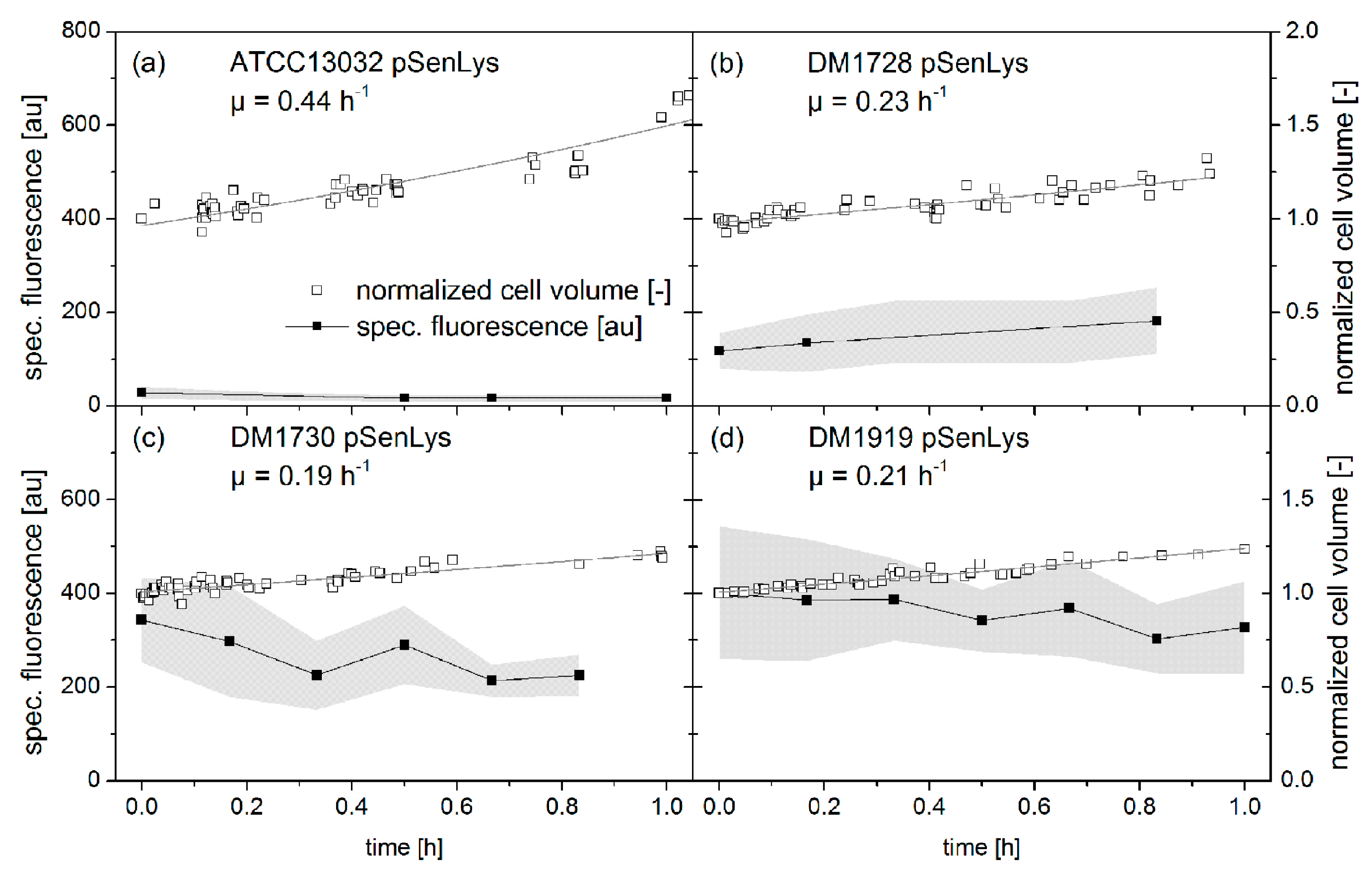
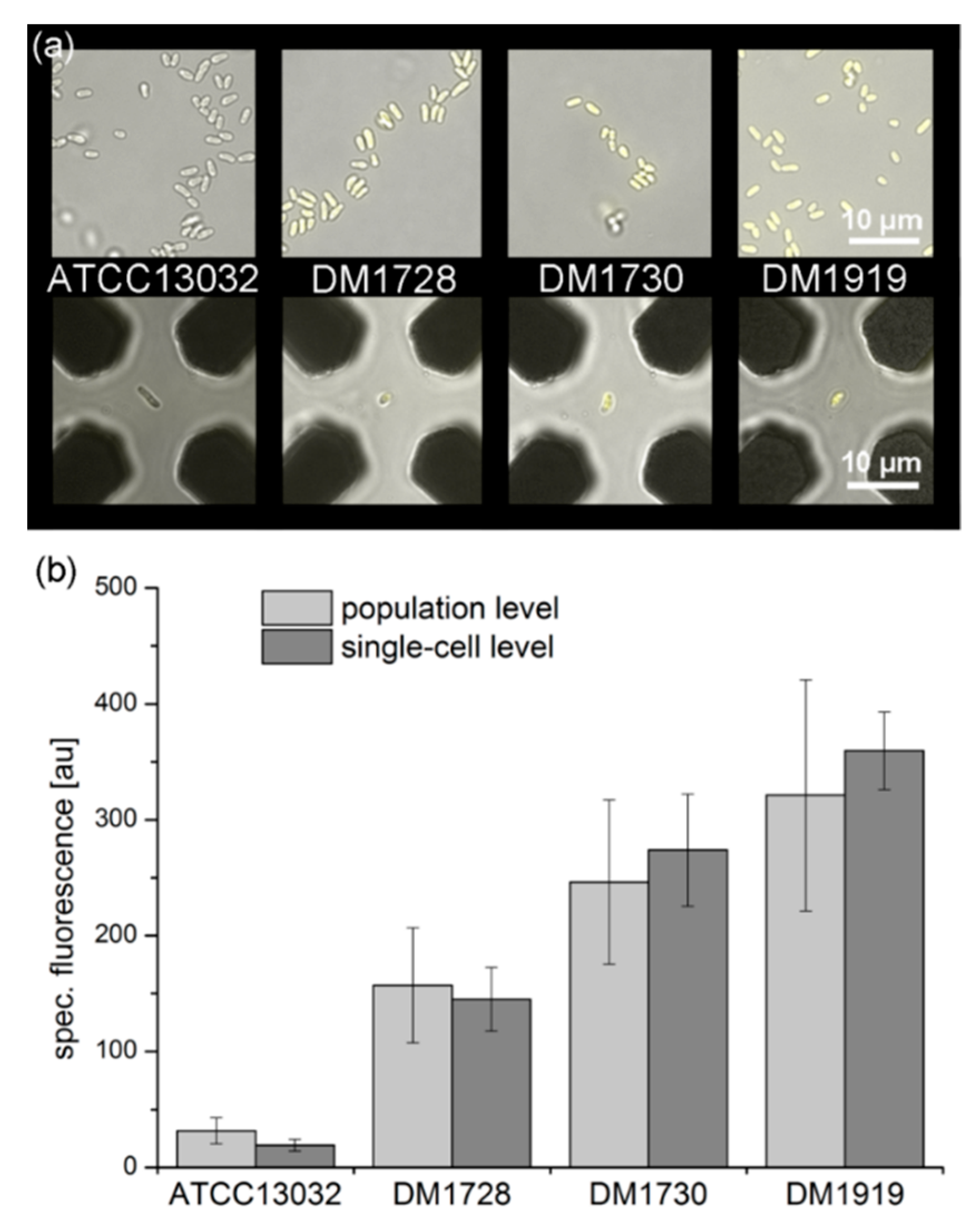
3.5.2. Qualitative eYFP-Reported l-Lysine Production at a Single-Cell Level

The new Envirostat system was applied to analyze cellular characteristics, concerning growth and productivity simultaneously. Four different C. glutamicum strains with different l-lysine productivities were cultivated and analyzed to monitor real-time eYFP-reported l-lysine production dynamics. The strains contained the optical l-lysine nanosensor pSenLys, which enabled the quantification of intracellular l-lysine amounts via fluorescence analyses [37,52].
The correlation of fluorescence readout with l-lysine production rates and accumulated l-lysine amounts (intracellular and extracellular) was validated in preliminary experiments [37]. For single-cell analyses the wildtype strain C. glutamicum ATCC13032 pSenLys and l-lysine producer strains C. glutamicum DM1728 pSenLys, DM1730 pSenLys, and DM1919 pSenLys were consecutively analyzed for a period of up to 60 min (Figure 8). Growth and fluorescence of individual cells were monitored. Since the cells were rotating during cultivation in the nDEP octupole cage, cells were not always in focus and it was not feasible to analyze every time-point. Cells were growing exponentially with rates of 0.44 h−1 for the wildtype strain C. glutamicum ATCC13032 pSenLys (Figure 8a) and of around 0.21 h−1 for the three l-lysine producer strains (C. glutamicum DM1728: 0.23 h−1, DM1730: 0.19 h−1, DM1919: 0.21 h−1) (Figure 8b–d). The comparison of specific growth rates of C. glutamicum DM1730 pSenLys in the nDEP octupole with (Figure 8b) and without fluorescence excitation (Figure 7) revealed a decrease of 63%. This decrease was triggered by exposing the cells to fluorescent excitation every 10 min. The production of reactive oxygen species, upon eYFP excitation, could lead to light-induced damage of proteins, nucleic acids or membrane lipids and altered cell physiology [53,54]. That explained the reduction in growth rate of C. glutamicum DM1730 pSenLys cells exposed to fluorescence excitation. Specific growth rates of population-based cultivations in shake flasks were the same for C. glutamicum ATCC13032 pSenLys (0.45 h−1 ± 0.02) and around twice as high as for single-cell cultivation for the l-lysine producing strains (C. glutamicum DM1728: 0.45 h−1 ± 0.01, DM1730: 0.38 h−1 ± 0.04, DM1919: 0.40 h−1 ± 0.02). It can be assumed that the extent of damage correlated to the fluorophore concentration [54]. Cells which were producing more fluorescent proteins (Figure 8b–d) had lower specific growth rates compared to population-based cultivations. It seemed that C. glutamicum is highly sensitive to fluorescence excitation. However, all cells were growing and therefore metabolically active during measurement, while trapped in the octupole nDEP cage. In general, it was possible to follow the dynamic l-lysine-dependent eYFP-production of single cells, which remained constant for all strains during the measurement time.
The dynamic production of eYFP of single C. glutamicum cells was systematically analyzed and compared to the average productivity of the corresponding population (Figure 9). Cells were isolated and analyzed in the microfluidic chip (Figure 9a) as described above. The average specific fluorescence intensities were calculated over time, based on 3 to 7 time points within 50 to 60 min for each strain (Figure 9b). Furthermore, cells were cultivated in shake flasks and samples for fluorescence analyses were taken in the exponential growth phase (Figure 9a). For each strain, specific fluorescence intensities of 25 cells were averaged (Figure 9b). The specific fluorescence intensity reflected the respective different intracellular l-lysine concentration of the four C. glutamicum strains. The level of specific fluorescence intensity was the lowest for the wildtype, and the highest for the producer strain C. glutamicum DM1919 for population- and single-cell-based experiments. The same gradations of specific fluorescence intensities were observed for measurements of l-lysine producing single cells and at a population level (Figure 9b).
Figure 8. Normalized cell volumes and specific fluorescence of (a) C. glutamicum ATCC13032, (b) DM1728, (c) DM1730 and (d) DM1919. All strains carried sensor plasmid pSenLys for l-lysine-dependent eYFP production. The cell volumes were normalized to the initial cell volume of the respective experiment and fitted exponentially. Fluorescence intensities were measured every 10 min with an eGFP-filter set (λex = 440–470 nm; λem = 525–550 nm) at an exposure time of 700 ms. The grey area indicates the standard deviation of fluorescence intensity measurements.
Micromachines 06 01459 g008
Figure 9. Specific fluorescence of l-lysine producing C. glutamicum strains (DM1728, DM1730, DM1919) and the wildtype strain C. glutamicum ATCC13032, all carrying pSenLys. (a) Microscopic overlays of bright field and fluorescence channel image for each strain from populations in the exponential phase cultivated in shake flasks (excitation for 200 ms, λex = 440–470 nm; λem = 525–550 nm) and single cells trapped in the nDEP octupole cage (excitation for 700 ms, λex = 440–470 nm; λem = 525–550 nm). (b) Specific fluorescence of cells originating from a population shake flasks and single cells trapped in the octupole cage. For measuring fluorescence intensities at the population level: 25 cells of the respective strain were averaged; samples originated from one time point with the corresponding standard deviation. For measuring fluorescence intensities at the single-cell level: cells were measured for a period of at least 50 min and maximal 60 min, time series were averaged and the time-dependent standard deviations are shown.
Micromachines 06 01459 g009
These results demonstrated that, next to growth, the l-lysine-dependent eYFP production was maintained during single-cell analyses in the Envirostat system. Different amounts of intracellular accumulated cytosolic eYFP were distinguished of cells cultivated in the Envirostat system and quantitative fluorescence analyses were feasible.
In a subsequent step, the specificity of cell trapping with the octupole nDEP cage was tested by trapping a previously selected cell with especially high or low production of eYFP. This approach would allow studying specific phenotypes from a population, e.g., in this case high- or low-fluorescing cells representing high/low levels of l-lysine-dependent eYFP production. Therefore, target-oriented trapping of a high- and a low-fluorescing cell from a random combination was performed. The wildtype strain C. glutamicum ATCC13032 pSenLys was pre-cultivated on two different minimal media, containing 50 mM l-lysine and without added l-lysine, respectively. Hence, the mixture consisted of non-fluorescing and high-fluorescing cells, since the extracellular added l-lysine was taken up and induced eYFP-production. With the cell suspension, selected trapping of fluorescing and non-fluorescing cells was performed successfully. The proof-of-principle for trapping a pre-selected cell with specific phenotypes was done with the new Envirostat system. In future experiments, striking phenotypes can be trapped selectively from a cell suspension in order to examine specific phenotypes coupled to a visual measurement value like cell morphology or the read-out of biosensors.
Quantitative fluorescence analyses at a single-cell level were applicable with the developed LOC device. Our results show that specific phenotypes can be reliably separated, and quantitative real-time monitoring of intracellular fluorescent proteins is possible in the defined environment of the Envirostat system.

4. Conclusions

This study presents a versatile and chemically inert Envirostat system for biological and chemical analyses of single microbial cells in defined environments. Through the application of a novel direct fusion bonding process, the LOC device exhibited extensive resistance towards solvents, operational stability, and minimized adsorption of biomolecules. Special emphasis was placed on the preservation of functionality and selectivity of the electrodes after thermal bonding, as well as a high efficiency of the cell trapping process with nDEP. Monitoring growth and production dynamics of amino acid secreting bacterium C. glutamicum confirmed the applicability of the LOC. The results demonstrate the suitability of the Envirostat system for advanced single-cell studies, where robustness and chemically inert surfaces are essential parameters, and open the door for quantitative secretome analyses.

Acknowledgments

We acknowledge the Graduate Cluster Industrial Biotechnology (CLIB 2021) for funding. The research is financed by the Federal Ministry for Economic Affairs and Energy and supported by the Ministry of Innovation, Science, Research and Technology of North-Rhine Westphalia. The employed C. glutamicum strains containing sensor plasmid pSenLys were kindly provided by L. Eggeling and S. Binder (Institute of Bio- and Geoscience, IBG-1, Forschungszentrum Jülich GmbH, D-52425 Jülich, Germany).

Author contributions

Katrin Rosenthal designed the LOC device, designed and performed the experiments, analyzed the data and wrote the manuscript. Floris Falke manufactured the microfluidic chips and optimized the manufacturing process. Oliver Frick supervised experiments and proofread the manuscript. Christian Dusny designed the LOC device, designed and supervised experiments, and proofread the manuscript. Andreas Schmid supervised the project and proofread the manuscript.

Conflicts of Interest

The authors declare no conflict of interest.

References

  1. Schmid, A.; Kortmann, H.; Dittrich, P.S.; Blank, L.M. Chemical and biological single cell analysis. Curr. Opin. Biotechnol. 2010, 21, 12–20. [Google Scholar] [CrossRef] [PubMed]
  2. Arriaga, E.A. Determining biological noise via single cell analysis. Anal. Bioanal. Chem. 2009, 393, 73–80. [Google Scholar] [CrossRef] [PubMed]
  3. Love, K.R.; Bagh, S.; Choi, J.; Love, J.C. Microtools for single-cell analysis in biopharmaceutical development and manufacturing. Trends Biotechnol. 2013, 31, 280–286. [Google Scholar] [CrossRef] [PubMed]
  4. Dusny, C.; Schmid, A. Challenging biological limits with microfluidic single cell analysis. Microb. Biotechnol. 2015, 8, 23–25. [Google Scholar] [CrossRef] [PubMed]
  5. Dusny, C.; Schmid, A. Microfluidic single-cell analysis links boundary environments and individual microbial phenotypes. Environ. Microbiol. 2015, 17, 1839–1856. [Google Scholar] [CrossRef] [PubMed]
  6. Ishii, S.; Tago, K.; Senoo, K. Single-cell analysis and isolation for microbiology and biotechnology: Methods and applications. Appl. Microbiol. Biotechnol. 2010, 86, 1281–1292. [Google Scholar] [CrossRef] [PubMed]
  7. Brehm-Stecher, B.F.; Johnson, E.A. Single-cell microbiology: Tools, technologies, and applications. Microbiol. Mol. Biol. Rev. 2004, 68, 538–559. [Google Scholar] [CrossRef] [PubMed]
  8. Qian, C.; Huang, H.B.; Chen, L.G.; Li, X.P.; Ge, Z.B.; Chen, T.; Yang, Z.; Sun, L.N. Dielectrophoresis for bioparticle manipulation. International Journal of Molecular Sciences 2014, 15, 18281–18309. [Google Scholar] [CrossRef] [PubMed]
  9. Voldman, J. Electrical forces for microscale cell manipulation. Annu. Rev. Biomed. Eng. 2006, 8, 425–454. [Google Scholar] [CrossRef] [PubMed]
  10. Li, M.; Li, S.B.; Cao, W.B.; Li, W.H.; Wen, W.J.; Alici, G. Improved concentration and separation of particles in a 3D dielectrophoretic chip integrating focusing, aligning and trapping. Microfluid. Nanofluidics 2013, 14, 527–539. [Google Scholar] [CrossRef]
  11. Dusny, C.; Fritzsch, F.S.O.; Frick, O.; Schmid, A. Isolated microbial single cells and resulting micropopulations grow faster in controlled environments. Appl. Environ. Microbiol. 2012, 78, 7132–7136. [Google Scholar] [CrossRef] [PubMed]
  12. Fritzsch, F.S.; Rosenthal, K.; Kampert, A.; Howitz, S.; Dusny, C.; Blank, L.M.; Schmid, A. Picoliter nDEP traps enable time-resolved contactless single bacterial cell analysis in controlled microenvironments. Lab Chip 2013, 13, 397–408. [Google Scholar] [CrossRef] [PubMed]
  13. Kortmann, H.; Chasanis, P.; Blank, L.M.; Franzke, J.; Kenig, E.; Schmid, A. The Envirostat - A new bioreactor concept. Lab Chip 2009, 9, 576–585. [Google Scholar] [CrossRef] [PubMed]
  14. Dusny, C.; Gruenberger, A.; Probst, C.; Wiechert, W.; Kohlheyer, D.; Schmid, A. Technical bias of microcultivation environments on single-cell physiology. Lab Chip 2015, 15, 1822–1834. [Google Scholar] [CrossRef] [PubMed]
  15. Waldbaur, A.; Rapp, H.; Lange, K.; Rapp, B.E. Let there be chip-towards rapid prototyping of microfluidic devices: One-step manufacturing processes. Anal. Methods 2011, 3, 2681–2716. [Google Scholar] [CrossRef]
  16. Duffy, D.C.; McDonald, J.C.; Schueller, O.J.; Whitesides, G.M. Rapid prototyping of microfluidic systems in poly(dimethylsiloxane). Anal. Chem. 1998, 70, 4974–4984. [Google Scholar] [CrossRef] [PubMed]
  17. Scharnweber, T.; Truckenmueller, R.; Schneider, A.M.; Welle, A.; Reinhardt, M.; Giselbrecht, S. Rapid prototyping of microstructures in polydimethylsiloxane (PDMS) by direct UV-lithography. Lab Chip 2011, 11, 1368–1371. [Google Scholar] [CrossRef] [PubMed]
  18. Kuncova-Kallio, J.; Kallio, P.J. In PDMS and its suitability for analytical microfluidic devices. In Conference proceedings: 28th Annual International Conference of the IEEE Engineering in Medicine and Biology Society, New York, NY, USA, 30 August–3 September 2006; 2006; pp. 2486–2489. [Google Scholar]
  19. Li, N.; Schwartz, M.; Ionescu-Zanetti, C. PDMS compound adsorption in context. J. Biomol. Screen. 2009, 14, 194–202. [Google Scholar] [PubMed]
  20. Velve-Casquillas, G.; le Berre, M.; Piel, M.; Tran, P.T. Microfluidic tools for cell biological research. Nano today 2010, 5, 28–47. [Google Scholar] [CrossRef] [PubMed]
  21. Tan, C.; Saurabh, S.; Bruchez, M.P.; Schwartz, R.; Leduc, P. Molecular crowding shapes gene expression in synthetic cellular nanosystems. Nat. Nanotechnol. 2013, 8, 602–608. [Google Scholar] [CrossRef] [PubMed]
  22. Bodas, D.; Khan-Malek, C. Hydrophilization and hydrophobic recovery of PDMS by oxygen plasma and chemical treatment - An SEM investigation. Sens. Actuators B Chem. 2007, 123, 368–373. [Google Scholar] [CrossRef]
  23. Wang, J.D.; Douville, N.J.; Takayama, S.; ElSayed, M. Quantitative analysis of molecular absorption into PDMS microfluidic channels. Ann. Biomed. Eng. 2012, 40, 1862–1873. [Google Scholar] [CrossRef] [PubMed]
  24. Iliescu, C.; Taylor, H.; Avram, M.; Miao, J.; Franssila, S. A practical guide for the fabrication of microfluidic devices using glass and silicon. Biomicrofluidics 2012, 6, 016505. [Google Scholar] [CrossRef] [PubMed]
  25. Mazurczyk, R.; Mansfield, C.D.; Lygan, M. Glass microstructure capping and bonding techniques. Methods Mol. Biol. 2013, 949, 141–151. [Google Scholar] [PubMed]
  26. Becker, H.; Locascio, L.E. Polymer microfluidic devices. Talanta 2002, 56, 267–287. [Google Scholar] [CrossRef]
  27. Temiz, Y.; Lovchik, R.D.; Kaigala, G.V.; Delamarche, E. Lab-on-a-chip devices: How to close and plug the lab? Microelectron. Eng. 2015, 132, 156–175. [Google Scholar] [CrossRef]
  28. Niklaus, F.; Stemme, G.; Lu, J.Q.; Gutmann, R.J. Adhesive wafer bonding. J. Appl. Phys. 2006, 99, 031101. [Google Scholar] [CrossRef]
  29. Schmidt, M.A. Wafer-to-wafer bonding for microstructure formation. Proc. IEEE 1998, 86, 1575–1585. [Google Scholar] [CrossRef]
  30. Puigcorbe, J.; Vogel, D.; Michel, B.; Vila, A.; Gracia, I.; Cane, C.; Morante, J.R. High temperature degradation of Pt/Ti electrodes in micro-hotplate gas sensors. J. Micromech. Microeng. 2003, 13, 119–124. [Google Scholar] [CrossRef]
  31. Rosenthal, A.; Taff, B.M.; Voldman, J. Quantitative modeling of dielectrophoretic traps. Lab Chip 2006, 6, 508–515. [Google Scholar] [CrossRef] [PubMed]
  32. Schnelle, T.; Hagedorn, R.; Fuhr, G.; Fiedler, S.; Mueller, T. Three-dimensional electric field traps for manipulation of cells—calculation and experimental verification. Biochim. Biophys. Acta 1993, 1157, 127–140. [Google Scholar] [CrossRef]
  33. Fuhr, G.; Arnold, W.M.; Hagedorn, R.; Muller, T.; Benecke, W.; Wagner, B.; Zimmermann, U. Levitation, holding, and rotation of cells within traps made by high-frequency fields. Biochim. Biophys. Acta 1992, 1108, 215–223. [Google Scholar] [CrossRef]
  34. Seger-Sauli, U.; Panayiotou, M.; Schnydrig, S.; Jordan, M.; Renaud, P. Temperature measurements in microfluidic systems: Heat dissipation of negative dielectrophoresis barriers. Electrophoresis 2005, 26, 2239–2246. [Google Scholar] [CrossRef] [PubMed]
  35. Jaeger, M.S.; Mueller, T.; Schnelle, T. Thermometry in dielectrophoresis chips for contact-free cell handling. J. Phys. D Appl. Phys. 2007, 40, 95–105. [Google Scholar] [CrossRef]
  36. Schnelle, T.; Mueller, T.; Fuhr, G. Trapping in AC octode field cages. J. Electrost. 2000, 50, 17–29. [Google Scholar] [CrossRef]
  37. Binder, S.; Schendzielorz, G.; Stabler, N.; Krumbach, K.; Hoffmann, K.; Bott, M.; Eggeling, L. A high-throughput approach to identify genomic variants of bacterial metabolite producers at the single-cell level. Genome Biol. 2012, 13, R40. [Google Scholar] [CrossRef] [PubMed]
  38. Keilhauer, C.; Eggeling, L.; Sahm, H. Isoleucine synthesis in Corynebacterium glutamicum - Molecular analysis of the Ilvb-Ilvn-Ilvc operon. J. Bacteriol. 1993, 175, 5595–5603. [Google Scholar] [PubMed]
  39. Abe, S.; Takayama, K.I.; Kinoshit, S. Taxonomical studies on glutamic acid-producing bacteria. J. Gen. Appl. Microbiol. 1967, 13, 279–301. [Google Scholar] [CrossRef]
  40. Blombach, B.; Hans, S.; Bathe, B.; Eikmanns, B.J. Acetohydroxyacid synthase, a novel target for improvement of l-lysine production by Corynebacterium glutamicum. Appl. Environ. Microbiol. 2009, 75, 419–427. [Google Scholar] [CrossRef] [PubMed]
  41. Duan, C.; Wang, W.; Xie, Q. Review article: Fabrication of nanofluidic devices. Biomicrofluidics 2013, 7, 26501. [Google Scholar] [CrossRef] [PubMed]
  42. Conradie, E.H.; Moore, D.F. SU-8 thick photoresist processing as a functional material for MEMS applications. J. Micromech. Microeng. 2002, 12, 368–374. [Google Scholar] [CrossRef]
  43. Tsao, C.W.; DeVoe, D.L. Bonding of thermoplastic polymer microfluidics. Microfluid. Nanofluidics 2009, 6, 1–16. [Google Scholar] [CrossRef]
  44. Kawamura, M.; Mashima, T.; Abe, Y.; Sasaki, K. Formation of ultra-thin continuous Pt and Al films by RF sputtering. Thin Solid Films 2000, 377, 537–542. [Google Scholar] [CrossRef]
  45. Lacy, F. Developing a theoretical relationship between electrical resistivity, temperature, and film thickness for conductors. Nanoscale Res. Lett. 2011, 6, 1–14. [Google Scholar] [CrossRef] [PubMed]
  46. Jezequel, N.; Lagomarsino, M.C.; Heslot, F.; Thomen, P. Long-term diversity and genome adaptation of Acinetobacter baylyi in a minimal-medium chemostat. Genome Biol. Evol. 2013, 5, 87–97. [Google Scholar] [CrossRef] [PubMed]
  47. Berkhout, J.; Bosdriesz, E.; Nikerel, E.; Molenaar, D.; de Ridder, D.; Teusink, B.; Bruggeman, F.J. How biochemical constraints of cellular growth shape evolutionary adaptations in metabolism. Genetics 2013, 194, 505–512. [Google Scholar] [CrossRef] [PubMed]
  48. Franzel, B.; Poetsch, A.; Trotschel, C.; Persicke, M.; Kalinowski, J.; Wolters, D.A. Quantitative proteomic overview on the Corynebacterium glutamicum l-lysine producing strain DM1730. J. Proteom. 2010, 73, 2336–2353. [Google Scholar] [CrossRef] [PubMed]
  49. Gruenberger, A.; Paczia, N.; Probst, C.; Schendzielorz, G.; Eggeling, L.; Noack, S.; Wiechert, W.; Kohlheyer, D. A disposable picolitre bioreactor for cultivation and investigation of industrially relevant bacteria on the single cell level. Lab Chip 2012, 12, 2060–2068. [Google Scholar] [CrossRef] [PubMed]
  50. Gruenberger, A.; van Ooyen, J.; Paczia, N.; Rohe, P.; Schiendzielorz, G.; Eggeling, L.; Wiechert, W.; Kohlheyer, D.; Noack, S. Beyond growth rate 0.6: Corynebacterium glutamicum cultivated in highly diluted environments. Biotechnol. Bioeng. 2013, 110, 220–228. [Google Scholar] [CrossRef] [PubMed]
  51. Unthan, S.; Gruenberger, A.; van Ooyen, J.; Gaetgens, J.; Heinrich, J.; Paczia, N.; Wiechert, W.; Kohlheyer, D.; Noack, S. Beyond growth rate 0.6: What drives Corynebacterium glutamicum to higher growth rates in defined medium. Biotechnol. Bioeng. 2014, 111, 359–371. [Google Scholar] [CrossRef] [PubMed]
  52. Binder, S.; Siedler, S.; Marienhagen, J.; Bott, M.; Eggeling, L. Recombineering in Corynebacterium glutamicum combined with optical nanosensors: A general strategy for fast producer strain generation. Nucleic Acids Res. 2013, 41, 6360–6369. [Google Scholar] [CrossRef] [PubMed]
  53. Dixit, R.; Cyr, R. Cell damage and reactive oxygen species production induced by fluorescence microscopy: Effect on mitosis and guidelines for non-invasive fluorescence microscopy. Plant J. 2003, 36, 280–290. [Google Scholar] [CrossRef] [PubMed]
  54. Dailey, M.E. Handbook of biological confocal microscopy, 3rd ed.; Springer US: New York, NY, USA, 2006; pp. 381–403. [Google Scholar]

