Article

Generation of Nanoliter Droplets on Demand at Hundred-Hz Frequencies

Institute of Physical Chemistry, Polish Academy of Sciences, Kasprzaka 44/52, 01-224 Warsaw, Poland
*
Author to whom correspondence should be addressed.
Micromachines 2014, 5(4), 1002-1011; https://doi.org/10.3390/mi5041002
Submission received: 25 August 2014 / Revised: 30 October 2014 / Accepted: 30 October 2014 / Published: 4 November 2014

Abstract

:
We describe a precision micropump for generation of precisely metered micro-aliquots of liquid at high rates. The use of custom designed piezoelectric valves positioned externally to the microfluidic chip allows for on-demand formation of micro-droplets with online control of their individual volumes from nLs to μLs at frequencies up to 400 Hz. The system offers precision of administering volumes of 1% and of time of emission of <0.5 ms. The use of a piezoelectric actuator provides two distinct vistas for controlling the volume of the droplets—either by digital control of the “open” interval or by analogue tuning of the lumen of the valve. Fast and precise generation of droplets make this system a perfect constituent module for microfluidic high-speed combinatorial screening schemes.

Graphical Abstract

1. Introduction

Droplet microfluidic techniques support almost all kinds of reactions in chemistry, biochemistry, and microbiology with the most pronounced advantages brought in the screening of large random libraries [1,2,3]. The most important and outstanding challenges in construction of multiphase microfluidic systems include automation of the operations on individually addressable microdroplets. Preferably, such individual control over the timing of flow, volumes and content of drops should be exerted with high precision and in a possibly inexpensive format, preferably, with disposable chips that minimize the cost of operation and the risks of cross-contamination between experiments. Lab-on-Chip systems that allow for fast and, in particular, precise generation of droplets of predefined volume and composition may find a wide variety of applications in biochemistry, especially in high-throughput screening. For example, they can be used for high-throughput screening and bioassays. Also, they will make it simple to run digital tests, i.e., digital polymerase chain reaction (PCR) [4,5,6] and digital enzyme-linked immunosorbent assay (ELISA) [6,7], in Lab-on-Chip systems, as they allow to generate large numbers of droplets of precisely defined volume and composition.
Churski et al. [8] proposed the use of external electromagnetic valves for the technical simplicity of the approach and for its compatibility with single-layer chips fabricated in virtually any material. The disadvantage of the electromagnetic valves used in the demonstration of the system [8] and in an integrated system for studying epistatic interactions between antibiotics [9] is the limited rate of operation of the coil actuators. One straightforward way to alleviate this problem is to use the much faster piezoelectric actuators as they offer high speed and precise reproducibility of motion. Piezoelectric actuators integrated with microfluidic chips have been used for ejection [10], sorting [11] and generation [12,13,14,15] of droplets.
There are a number of reports on generation of droplets on demand in microfluidic systems. The approaches include both integrated actuators [12,13,14] and modular designs [8,16] that lower the complexity of the microfluidic chips and allow for their easy exchange. Piezoelectric actuators have been shown to generate droplets with high precision (coefficient of variation (CV) ~0.3% [12]). The range of volumes expressed as the ratio of the volume of largest droplet that can be generated to the smallest drop is yet typically small, less than 10 in the systems utilizing piezo-electric actuators [12,13,14]. Other schemes of actuation increase the dynamic range of volumes to above few tens [16,17] or even approximately one hundred [8]. Some of the solutions operate at high rates, for example the “pico-injectors” reported by Abate et al. [16] generate droplets at frequency of up to 10 kHz, yet the precision of these systems is small with coefficients of variation typically above 10% [16,17]. In summary, there is no demonstration to date of a system combining high precision of dosing, wide range of volumes and high rates of operation.
Here we report the construction and application of an external piezoelectric valve for the generation of micro-droplets on demand in a wide range of volumes with much higher accuracy than available in current solutions. We report on the speed and precision of the system and discuss the use of the valve in larger, more complex microfluidic systems. Our design, being external to the microfluidic chip, is not influenced by the choice of the chip material. Therefore it can be used not only for Polydimethylsiloxane (PDMS), but also for polycarbonate (PC), glass or silicon chips. Moreover, an external generator can be used multiple times in various systems, which lowers the cost of a single chemical reaction and the complexity of the experimental set-up. Furthermore, if there are two or more generators integrated with the chip, they can influence each other spoiling their performance. External generators are free from this problem. Such robustness of external generators, including the design presented here, is crucial for the reproducibility of biological and biochemical reactions that require very precise and accurate dosing of substrates.
We report a microfluidic system that can generate precisely metered droplets on demand at frequencies in excess of hundred Hz. The system uses custom piezo-electric valves positioned outside the microfluidic chip. The valves control the time of emission of each individual droplet with a precision of ca. 0.5 ms, and the volume of each droplet with a precision better than 10 pL within the whole 1 nL to 20 μL range (over 4 log) of volumes that can be administered into each drop. The system is compatible with a wide range of materials of which the chips are made and with various dimensions of the microchannels. We demonstrate both digital and analogue control of the volume of the droplets, and operation of the system paced at up to 400 Hz.

2. Experimental Section

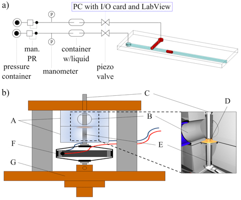
2.1. Microfluidic Chip

In the tests of the range and precision of administering volumes of micro-droplets and of the rate of operation of the valve we used simple microfluidic chips comprising a T-junction [18,19]. We fabricated polycarbonate chips in 5-mm thick plates (Macroclear, Bayer, Leverkusen, Germany) using milling machine (MSG4025, Ergwind, Gdansk, Poland). The mean of absolute values of profile of milled surface of channel averaged over the profile equals 2.6 μm, and the maximum height of the profile was 4.8 μm (calculated with the use of Bruker CountourGT-K0 profilometer, Bruker, Billerica, MA, USA). The milled plates were thermally bonded to flat 2-mm plates by compressing them together (30 min, 130 °C). Two valves (Figure 1a) were supplied with liquids (one with hexadecane with 0.5% (w/w) Span 80, second with distilled water) from pressurized reservoirs. We connected the chip inlets to resistive steel capillaries (outer diameter (O.D.) 200 μm, inner diameter (I.D.) 100 μm, length 1–5 m, Mifam, Milanowek, Poland) extending from the valves using short segments of Tygon tubing (~2 cm, O.D. 2.01 mm, I.D. 0.19 mm, Ismatec, Glattbrugg, Switzerland) to connect the capillaries with the needles.
Figure 1. (a) Schematic diagram of the experimental system: each of the liquid supply lines comprises a pressurized reservoir, a valve, and a resistive capillary that interfaces the chip. (b) Scheme of the valve: A—the body of the valve, B—valve inlet, C—valve outlet (capillary tube), D—membrane, E—pushrod, F—piezoelectric actuator, G—brass-steel housing.
Micromachines 05 01002 g001

2.2. The Valve

We used APA40SM (Cedrat, Meylan, France, capacity of 1.8 μF) piezoelectric actuators, nominally providing up to 52 μm stroke, up to 4 kHz frequency (resonance frequency is 4.1 kHz without load), and up to 194 N of force. We milled the body of the valve (marked A in Figure 1, see also Figure S1 in supplementary) in a block of polycarbonate (PC). In the outlet of the body of the valve we placed a stainless steel capillary (C) of O.D. 1.3 mm and I.D. 1.1 mm and 2.5 cm length. The liquid was supplied to the valve (B) from a pressurized reservoir via a wide tubing (O.D. 6 mm, I.D. 4 mm). We used a polyester-laminated aluminium foil membrane (D) (150–110 μm thick aluminium foil and 20 μm thick polyester layer on both sides, Heinz Herenz Gmbh, Hamburg, Germany) to close the outlet of the valve. The membrane was pressed against the inlet into the steel capillary with a steel pushrod (E in Figure 1) of a diameter of 2 mm and a length of 15 mm, connected directly to the piezoelectric actuator (F in Figure 1). Both the valve and the actuator were mounted in a brass-steel housing (G) that allowed for fine tuning of the distance between the two parts with the use of a detachable micrometric screw (Thorlabs, Newton, NJ, USA). The actuator in the normal (extended) state was pressing the membrane down against the steel capillary, while applying electric potential withdrew the steel rod and allowed for a finite lumen between the edge of the steel capillary and the membrane. The valve provided for a displacement of up to 50 μm at frequencies of up to 400 Hz. Above 400 Hz, the inertia of the steel pushrod decreased the amplitude of motion of the actuator (Figure S2 in supplementary).

2.3. Amplifier

To control the piezoelectric actuator, we built a custom proportional voltage amplifier characterized by a 15× gain of the potential for 0–10 V input at frequencies from 0 to 4 kHz [20]. The amplifier allows us to control the piezoelectric actuator digitally (on/off) and with the pulse width modulation (PWM) with the duty cycle d (percent of time that the potential is on) ranging from 10% to 90% (Figure S3 in supplementary). One of the most important parameters of the voltage amplifier is the maximum current that it can supply to the actuator. Higher current allows us to control an actuator with larger capacitance for the same working frequency. Our amplifier supports the 3μF actuator at its full range of frequencies, i.e., up to 4 kHz. In our experiments we used the National Instrument (Austin, TX, USA) cards (PCIE-6321) that generated synchronized PWM signals for two amplifiers to ensure the proper control of the valves. Custom written LabView script enabled the change of duty cycle for each step. Our solution can be multiplied up to 24 independent amplifiers connected to valves.

2.4. Protocol of Generation of Droplets on Demand

A microfluidic droplet on demand (DOD) system should allow us to produce droplets of an arbitrary (i.e., within a possibly wide range) volume and at an arbitrary time of emission. In order to achieve a wide dynamic range of accessible volumes we actively control both immiscible phases [8]. In order to generate a droplet of required volume, the LabView protocol: (i) closes the flow of the continuous (oily) phase, (ii) opens the flow of the droplet (aqueous) phase and keeps it open for an interval topen, (iii) closes the flow of the droplet phase, and (iv) opens the flow of the continuous liquid to break-off the droplet and push it downstream of the junction. A well-performing DOD system should show an ideally linear relation between the interval topen and the volume V of the droplet.
Our system enables to connect a number of different sources of the flow with usually different chemical factors. The only condition for proper operation of a complex system is that each source of flow has a higher hydrodynamic resistance in the steel capillary than the hydrodynamic resistance of the microchannels on the chip and simultaneously has the comparable resistance with other sources. This is achieved with the use of long thin capillaries. We have described the rules for building these systems in Churski et al. [21], and shown examples of complex systems operated within this technology [22].

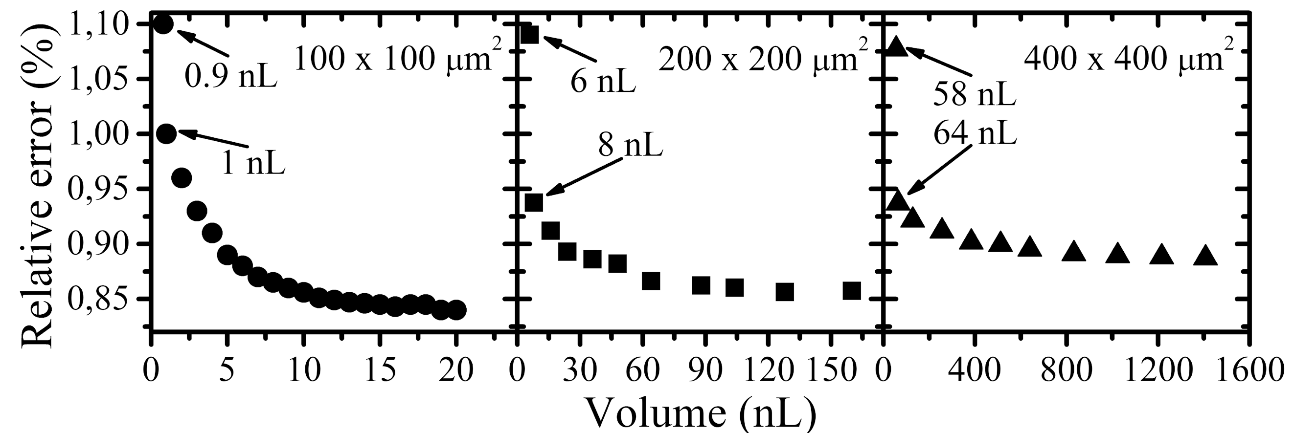
2.5. Measurement of the Volume of Droplets

We imaged the droplets with a fast camera (Photron PCI1024, Photron, Tokyo, Japan) through a microscope (Nikon Eclipse E200, Nikon, Tokyo, Japan). We measured the lengths of the droplets in a tube (I.D. 0.2 mm, polytetrafluoroethylene (PTFE), Bola, Grünsfeld, Germany) connected to a square cross-section microchannel and modeled their volume as a cylinder caped with two hemispheres. This model shape of the droplet may introduce small systematic error to the estimate of the volume, yet it does not compromise the measurement of the precision and reproducibility of the volumes of droplets generated on demand in our system. The applied technique allows us to measure the volume with the precision of 0.1 pL, which was limited by our ability to optically resolve the interfaces and the deformation of ends of droplets.

3. Results and Discussion

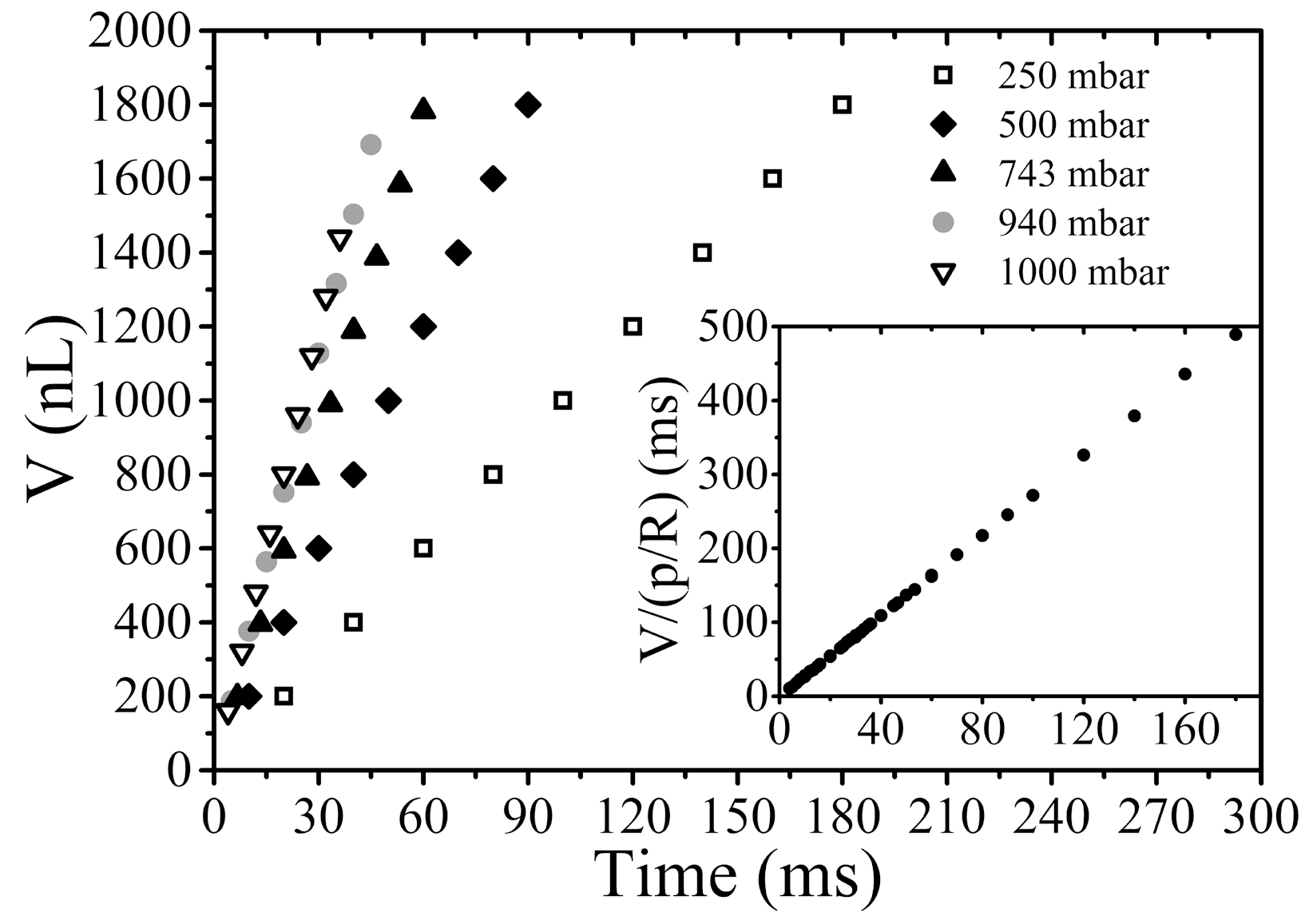
3.1. Tuning the Volume of Droplets via Timing the Valves

We first tested the ability of our system to control the volume of the droplets formed by changing the value of topen while keeping the constant electric potential (150 V) applied to the actuator. We recorded the volumes of droplets generated by our system at five different values of the pressure applied to the reservoir of water pwater. In all these experiments the pressure poil was constant (1500 mbar), resulting in the instantaneous rate of flow of oil being always 25 mL/h. We observed that (i) the volume of droplets increases linearly with increasing topen (Figure 2) and (ii) the rate of this increase is proportional to pwater. These results show that the rate of flow of the droplet phase can be well described with the Hagen-Poiseuille law ( Q ~ p R , where Q = d V d t is volumetric flow rate, Δp is the pressure drop and R is the length of capillary) for a viscous flow in a capillary (inset of Figure 2 shows relationship: V p R ~ t ).

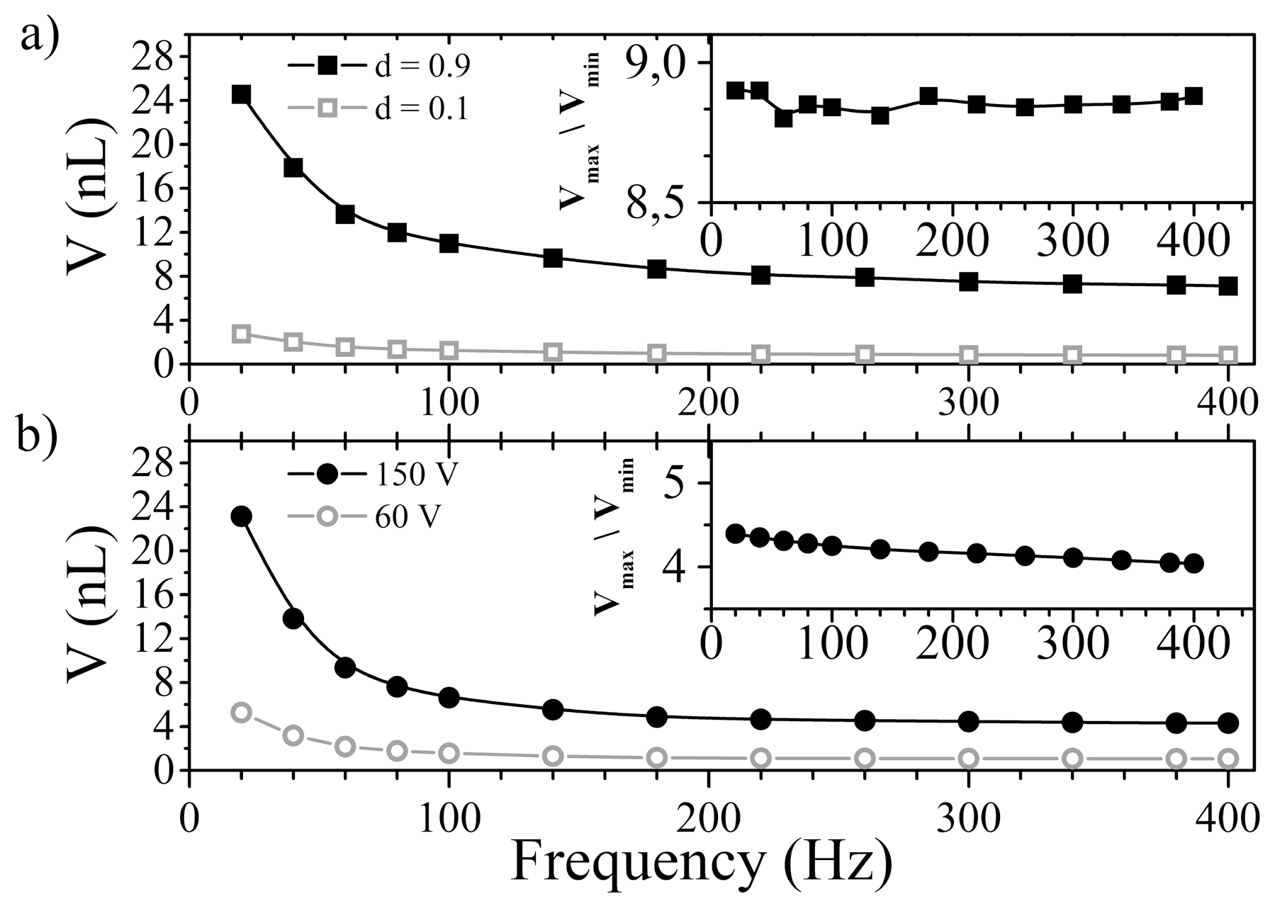
3.2. Tuning the Volume of Droplets Generated at a Constant Frequency

The system can be used to tune the volume of monodisperse droplets created at a constant frequency. If we set the duration of a single tact of the system as τ = 1/f, the interval topen when the valve for the droplet phase is open can be expressed as topen = d/f. We call d = topen/τ the duty cycle in analogy to the pulse width modulation technique (Figure S3). With the use of our setup we were able to tune d in the range of 0.1 to 0.9. This limits the dynamic range Ω of volumes to Ω = V d = 0.9 V d = 0.1   ~   9 . This is well reflected in our experimental results (Figure 3a). As we increase the frequency (decrease τ), the range of droplets that can be generated shifts to smaller volumes (V ~ topen = d/f), yet the ratio of the largest and smallest achievable droplets stays approximately constant ( V d = 0.9 V d = 0.1 ~ 0.9 f 0.1 f = 9 inset of Figure 3a).
Figure 2. The graph shows the volumes of droplets as a function of the interval topen and of the pressures pwater applied to the container with water. The inset shows almost perfect (99.6% level of compliance) agreement of the measured trends with the Hagen-Poiseuille law (see inset). The droplets were formed in 400 × 400 μm2 square cross-section channel.
Micromachines 05 01002 g002
Figure 3. Formation of drops of different volumes in a single cycle obtained in (a) digital control and (b) analogue control. Insets show the ratio of maximum to minimum volume of drops as a function of the frequency of valve operation. The droplets were formed in 100 × 100 μm2 square cross-section channel. During the experiments the values of pressure poil (1500 mbar) and pwater (2000 mbar) were constant.
Micromachines 05 01002 g003

3.3. Analogue Control

Similar function of tuning the volume of monodisperse drops produced at a fixed frequency can be achieved via the analogue control of the potential applied to the piezoelectric actuator. We fix the duty cycle d to 0.5 and change the voltage applied to the valve between 60 and 150 V. This corresponds to a range of 20 to 50 μm micrometers of deflection of the actuator (Figure S4 in supplementary). Figure 3b shows the dependence of the maximum and minimum volume that could be generated for a given frequency via this method. As one can see, the dynamic range of achievable volumes slightly decreases with increasing frequency (inset of Figure 3b).

3.4. Maximum Frequency of Operation

We quantified the range of frequencies at which droplets can be formed for a fixed set of parameters of the system (v = 200 mm/s—average velocity of the oil in the microchannel, d = 0.5, U = 150 V). The system operated correctly at frequencies lower than 400 Hz. In this regime all droplets were monodisperse, the maximum relative error in administering the volumes, expressed as the standard deviation of the diameter normalized by the mean (for at least 20 consecutive drops), was less than 1% (Figure 4).
Figure 4. Graph shows the relative error of formed droplets as a function of their volumes. Each chart corresponds to appropriate size of square cross-section of channel. Droplets were formed at constant frequency 400 Hz and the pressure applied to the container with water (2500 mbar) was fixed in all experiments. In turn, pressure applied to the container with oil was 4000 mbar for 100 × 100 μm2, 2400 mbar for 200 × 200 μm2, and 2000 mbar for 400 × 400 μm2, which resulted in constant volumetric flow of the oil in the microchannel in all instances. The smallest reproducibly (when relative error is lower than 1%) droplets are marked and they are comparable with the volume define by the cube of width of channel.
Micromachines 05 01002 g004

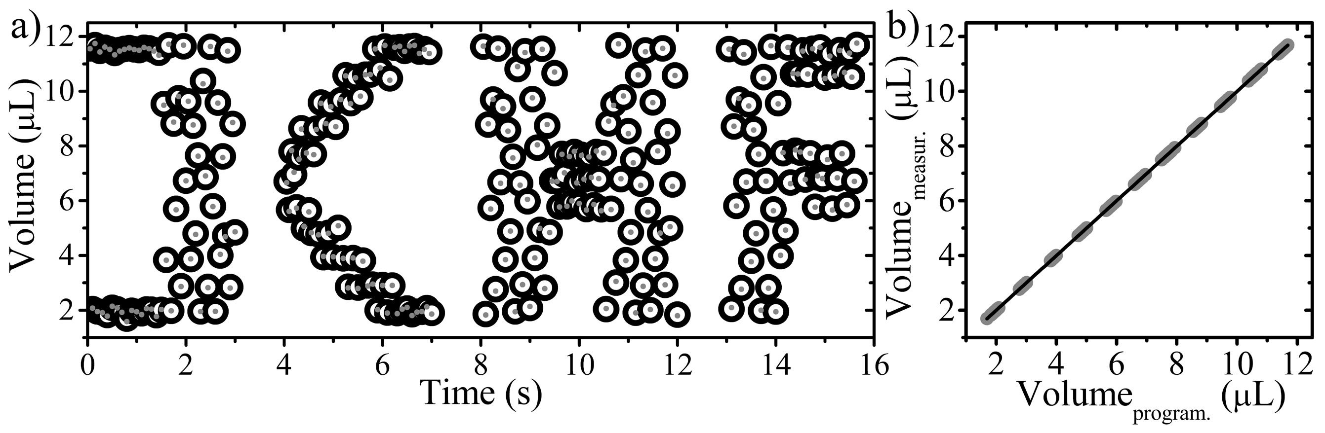
3.5. Generation of Arbitrary Sequences of Volumes of Droplets

We have also verified the ability of our system to generate sequences of droplets of varied, and arbitrarily predefined volume at a constant frequency (50 Hz—Figure 5, and 400 Hz—Figure S5 in supplementary) of operation. We first calibrated the relation between the volume V of the droplets and the duty cycle d:V(d), as explained above. We then programmed a sequence of volumes Vi of droplets into the script that controlled the valves. The protocol listed different values of the duty cycle di in each (i-th) cycle of the operation of the system. We then run the script using LabVIEW (National Instruments, Austin, TX, USA) and recorded a video to analyze the actual volumes of droplets produced. We used a sequence that—when plotted for volume against index of the droplet in the sequence—shows the acronym of our institute (“ICHF” for “Instytut CHemii Fizycznej”) (Figure 5). The apparent scatter (“bold font” of the letters) was intentionally programmed into the script. The measured volumes of droplets coincided within 99.8% with the programmed values. Figure S5 illustrates similar experiment in a smaller microchannel—i.e., 100 × 100 μm2, in which droplets were formed with 400 Hz frequencies. Correlation coefficient is equal to 0.9991 in this instance.
Such sequence can be used in larger, integrated systems [9,22,23], to merge droplets of different chemical composition to form sequences of mixtures that systematically screen the composition space of a reaction.
Figure 5. (a) The graph shows the pre-programmed (dots) and measured (open circles) volumes of droplets produced at 50 Hz in our system. The droplets were formed in 400 × 400 μm2 square cross-section channel. The scatter is intentional—o fill in the “body” of the letters coding for ICHF, the acronym of the Institute of Physical Chemistry (Instytut CHemii Fizycznej, Warszawa, Poland). (b) The graph illustrates the same sequence of droplets and shows the accuracy in forming of droplet on demand. Pearson correlation coefficient between measured and programmed volume of droplet is 0.998.
Micromachines 05 01002 g005

3.6. Durability of the Valve

We demonstrated the use of this system to issue droplets of varied, pre-defined, volumes at a constant frequency of forming. This scheme of operation may be particularly suitable for screening applications. To build robust systems on the basis of the design presented here one should consider using a proper material for the membrane. We checked that the foils that we used typically survived ca. 5 million cycles of opening and closing the valve and then quickly degraded.
Higher durability of the membrane would be also advisable as our system is external to the chip, and therefore can be used many times in different setups. This feature dramatically lowers the complication of disposable parts (chips) of the system and therefore the cost of a single measurement. This feature is particularly important for current applications of the micro-droplet techniques.

4. Conclusions

We reported an automated system for on-demand generation of micro-droplets, ranging in volume from 1 nL to 20 μL at frequencies ranging up to 400 Hz. The system uses a piezoelectric valve and offers high precision in administering of volume of liquid: we measured the standard deviation of the volumes of droplets to be well below 1% of the mean for the given set of values of the control parameters (Table S1 in supplementary).
The experiments prove that the performance of our system is independent from the cross section of the channel in the tested regime (100 × 100–400 × 400 μm2) and the applied membrane features sufficient durability. Generated droplets have volumes of pre-programmed values, and their appearance in the microchannel is strictly defined. Similar behavior of our piezoelectric valve is expectable in microchannels with width lower than 100 μm and the droplets should be generated with a good accuracy even at pL volume range, this however requires that the pressure head in the resistive capillary connecting the valve with the chip be at least 100 times greater than the typical pressure head in the microfluidic chip.
The presented system requires pre-filtered fluids to avoid blocking of the valve. This feature prevents also obstruction of the microchannels with debris, which is highly important especially in biological and medical applications.
The advantage of the presented system over the systems based on electromagnetic valves is the much higher frequency of droplet-on-demand generation with the same, or even higher precision in administering the volumes. The system that we report here can be integrated into screening systems operating at tens of Hz and on truly nano-liter volumes of the samples—a combination that surpasses the titier plate robotics by more than two orders of magnitude in the speed of operation and by at least an order of magnitude in the reaction volume.

Supplementary Materials

Supplementary materials can be accessed at: https://www.mdpi.com/2072-666X/5/4/1002/s1.

Acknowledgments

Project operated within the European Research Council Starting Grant 279647. Slawomir Jakiela and Pawel R. Debski also acknowledges financial support from the Polish Ministry of Science and Higher Education under the grant Iuventus Plus IP2012 015172.

Author Contributions

Slawomir Jakiela, Pawel R. Debski and Piotr Garstecki designed the experiments. Slawomir Jakiela and Bogdan Dabrowski developed and assembled the piezolectric valve. Slawomir Jakiela, Pawel R. Debski executed the experiments and together with Piotr Garstecki analyzed the results and wrote the manuscript.

Conflicts of Interest

The authors declare there are no conflicts of interest.

References

  1. Theberge, A.B.; Courtois, F.; Schaerli, Y.; Fischlechner, M.; Abell, C.; Hollfelder, F.; Huck, W.T.S. Microdroplets in microfluidics: An evolving platform for discoveries in chemistry and biology. Angew. Chem. Int. Ed. Engl. 2010, 49, 5846–5868. [Google Scholar] [CrossRef]
  2. Pompano, R.R.; Liu, W.; Du, W.; Ismagilov, R.F. Microfluidics using spatially defined arrays of droplets in one, two, and three dimensions. Annu. Rev. Anal. Chem. 2011, 4, 59–81. [Google Scholar] [CrossRef]
  3. Squires, T.M.; Quake, S.R. Microfluidics: Fluid physics at the nanoliter scale. Rev. Mod. Phys. 2005, 77, 977–1026. [Google Scholar] [CrossRef]
  4. Leng, X.; Zhang, W.; Wang, C.; Cui, L.; Yang, C.J. Agarose droplet microfluidics for highly parallel and efficient single molecule emulsion PCR. Lab Chip 2010, 10, 2841–2843. [Google Scholar] [CrossRef] [PubMed]
  5. Wang, M.S.; Nitin, N. Rapid detection of bacteriophages in starter culture using water-in-oil-in-water emulsion microdroplets. Appl. Microbiol. Biotechnol. 2014, 98, 8347–8355. [Google Scholar] [CrossRef] [PubMed]
  6. Witters, D.; Sun, B.; Begolo, S.; Rodriquez-Manzano, J.; Robles, W.; Ismagilov, R.F. Digital biology and chemistry. Lab Chip 2014, 14, 3225–3232. [Google Scholar] [CrossRef] [PubMed]
  7. Teste, B.; Ali-Cherif, A.; Viovy, J.L.; Malaquin, L. A low cost and high throughput magnetic bead-based immuno-agglutination assay in confined droplets. Lab Chip 2013, 13, 2344–2349. [Google Scholar] [PubMed]
  8. Churski, K.; Korczyk, P.; Garstecki, P. High-throughput automated droplet microfluidic system for screening of reaction conditions. Lab Chip 2010, 10, 816–818. [Google Scholar] [CrossRef] [PubMed]
  9. Churski, K.; Kaminski, T.S.; Jakiela, S.; Kamysz, W.; Baranska-Rybak, W.; Weibel, D.B.; Garstecki, P. Rapid screening of antibiotic toxicity in an automated microdroplet system. Lab Chip 2012, 12, 1629–1637. [Google Scholar] [CrossRef] [PubMed]
  10. Perccin, G.; Levin, L.; Khuri-Yakub, B.T. Piezoelectrically actuated droplet ejector. Rev. Sci. Instrum. 1997, 68, 4561–4563. [Google Scholar] [CrossRef]
  11. Chen, C.H.; Cho, S.H.; Tsai, F.; Erten, A.; Lo, Y.-H. Microfluidic cell sorter with integrated piezoelectric actuator. Biomed. Microdevices 2009, 11, 1223–1231. [Google Scholar] [CrossRef] [PubMed]
  12. Bransky, A.; Korin, N.; Khoury, M.; Levenberg, S. A microfluidic droplet generator based on a piezoelectric actuator. Lab Chip 2009, 9, 516–520. [Google Scholar] [CrossRef] [PubMed]
  13. Shemesh, J.; Bransky, A.; Khoury, M.; Levenberg, S. Advanced microfluidic droplet manipulation based on piezoelectric actuation. Biomed. Microdevices 2010, 12, 907–914. [Google Scholar] [CrossRef] [PubMed]
  14. Shemesh, J.; Nir, A.; Bransky, A.; Levenberg, S. Coalescence-assisted generation of single nanoliter droplets with predefined composition. Lab Chip 2011, 11, 3225–3230. [Google Scholar] [CrossRef] [PubMed]
  15. Xu, J.; Attinger, D. Drop on demand in a microfluidic chip. J. Micromech. Microeng. 2008, 18, 065020. [Google Scholar] [CrossRef]
  16. Abate, A.R.; Hung, T.; Mary, P.; Agresti, J.J.; Weitz, D.A. High-throughput injection with microfluidics using picoinjectors. Proc. Natl. Acad. Sci. 2010, 107, 19163–19166. [Google Scholar] [CrossRef] [PubMed]
  17. Tang, J.; Jofre, A.M.; Kishore, R.B.; Reiner, J.E.; Greene, M.E.; Lowman, G.M.; Denker, J.S.; Willis, C.C.C.; Helmerson, K.; Goldner, L.S. Generation and mixing of subfemtoliter aqueous droplets on demand. Anal. Chem. 2009, 81, 8041–8047. [Google Scholar] [CrossRef] [PubMed]
  18. Thorsen, T.; Roberts, R.W.; Arnold, F.H.; Quake, S.R. Dynamic pattern formation in a vesicle-generating microfluidic device. Phys. Rev. Lett. 2001, 86, 4163–4166. [Google Scholar] [CrossRef] [PubMed]
  19. Garstecki, P.; Fuerstman, M.J.; Stone, H.A.; Whitesides, G.M. Formation of droplets and bubbles in a microfluidic T-junction—Scaling and mechanism of break-up. Lab Chip 2006, 6, 437–446. [Google Scholar] [CrossRef]
  20. Jakiela, S.; Zaslona, J.; Michalski, J.A. Square wave driver for piezoceramic actuators. Actuators 2012, 1, 12–20. [Google Scholar] [CrossRef]
  21. Churski, K.; Nowacki, M.; Korczyk, P.M.; Garstecki, P. Simple modular systems for generation of droplets on demand. Lab Chip 2013, 13, 3689–3697. [Google Scholar] [CrossRef] [PubMed]
  22. Jakiela, S.; Kaminski, T.S.; Cybulski, O.; Weibel, D.B.; Garstecki, P. Bacterial growth and adaptation in microdroplet chemostats. Angew. Chem. Int. Ed. Engl. 2013, 52, 8908–8911. [Google Scholar] [CrossRef] [PubMed]
  23. Cao, J.; Kürsten, D.; Schneider, S.; Knauer, A.; Günther, P.M.; Köhler, J.M. Uncovering toxicological complexity by multi-dimensional screenings in microsegmented flow: Modulation of antibiotic interference by nanoparticles. Lab Chip 2012, 12, 474–484. [Google Scholar] [PubMed]

